WO2015178162A1 - エネルギー吸収装置、シートベルトリトラクタ及びシートベルト装置 - Google Patents
エネルギー吸収装置、シートベルトリトラクタ及びシートベルト装置 Download PDFInfo
- Publication number
- WO2015178162A1 WO2015178162A1 PCT/JP2015/062510 JP2015062510W WO2015178162A1 WO 2015178162 A1 WO2015178162 A1 WO 2015178162A1 JP 2015062510 W JP2015062510 W JP 2015062510W WO 2015178162 A1 WO2015178162 A1 WO 2015178162A1
- Authority
- WO
- WIPO (PCT)
- Prior art keywords
- clutch
- clutch disk
- casing
- energy absorbing
- absorbing device
- Prior art date
- Legal status (The legal status is an assumption and is not a legal conclusion. Google has not performed a legal analysis and makes no representation as to the accuracy of the status listed.)
- Ceased
Links
Images




Classifications
-
- B—PERFORMING OPERATIONS; TRANSPORTING
- B60—VEHICLES IN GENERAL
- B60R—VEHICLES, VEHICLE FITTINGS, OR VEHICLE PARTS, NOT OTHERWISE PROVIDED FOR
- B60R22/00—Safety belts or body harnesses in vehicles
- B60R22/28—Safety belts or body harnesses in vehicles incorporating energy-absorbing devices
-
- B—PERFORMING OPERATIONS; TRANSPORTING
- B60—VEHICLES IN GENERAL
- B60R—VEHICLES, VEHICLE FITTINGS, OR VEHICLE PARTS, NOT OTHERWISE PROVIDED FOR
- B60R22/00—Safety belts or body harnesses in vehicles
- B60R22/34—Belt retractors, e.g. reels
- B60R22/36—Belt retractors, e.g. reels self-locking in an emergency
- B60R22/40—Belt retractors, e.g. reels self-locking in an emergency responsive only to vehicle movement
-
- F—MECHANICAL ENGINEERING; LIGHTING; HEATING; WEAPONS; BLASTING
- F16—ENGINEERING ELEMENTS AND UNITS; GENERAL MEASURES FOR PRODUCING AND MAINTAINING EFFECTIVE FUNCTIONING OF MACHINES OR INSTALLATIONS; THERMAL INSULATION IN GENERAL
- F16F—SPRINGS; SHOCK-ABSORBERS; MEANS FOR DAMPING VIBRATION
- F16F15/00—Suppression of vibrations in systems; Means or arrangements for avoiding or reducing out-of-balance forces, e.g. due to motion
- F16F15/10—Suppression of vibrations in rotating systems by making use of members moving with the system
- F16F15/12—Suppression of vibrations in rotating systems by making use of members moving with the system using elastic members or friction-damping members, e.g. between a rotating shaft and a gyratory mass mounted thereon
- F16F15/129—Suppression of vibrations in rotating systems by making use of members moving with the system using elastic members or friction-damping members, e.g. between a rotating shaft and a gyratory mass mounted thereon characterised by friction-damping means
Definitions
- the present invention relates to an energy absorbing device, a seat belt retractor, and a seat belt device, and more particularly, an energy absorbing device disposed between relatively rotating objects, a seat belt retractor including the energy absorbing device, and the seat belt retractor.
- the present invention relates to a seat belt device provided with
- a winding drum (sometimes called a drum or a spool) that takes up a long item rotates the winding drum. Rotating motion relative to the supporting means which supports it.
- a long object is fully extended in a device that performs such relative movement, or when the winding drum stops during winding or rewinding, a large load is applied to the device or the long object. It is preferable to dispose an energy absorbing device.
- a typical example of such a winding device is a seat belt retractor used in a seat belt device (see, for example, Patent Document 1 or Patent Document 2).
- Patent Document 1 discloses a seat belt retractor in which a torsion bar and a wire are disposed between a winding drum and a ratchet gear that relatively rotate. According to such a seat belt retractor, energy that can be generated between the winding drum and the ratchet gear due to torsional deformation of the torsion bar and sliding deformation of the wire can be absorbed, and it is necessary for sliding deformation of the wire. It is possible to change the energy absorption characteristics by varying the appropriate pull-out load.
- Patent Document 2 discloses a vehicle force limiter device in which a ring disk (1, 3) and a swing member (2) are arranged between relatively rotating objects. According to such a device, when the swing member (2) rotates relative to the ring disc (1, 3), the protrusion (5) formed on the swing member (2) is caused to move to the ring disc (1, 3). ), The energy generated between the relatively rotating objects can be absorbed. In particular, in this apparatus, the kinetic energy varies depending on the rotational speed of the swing member (2), and the amount of energy absorption can be increased as the rotational speed of the swing member (2) increases.
- Such an event is not limited to the seat belt retractor.
- the phenomenon may occur in a winding device that winds long objects (woven fabric, deck, etc.) having different thicknesses and types.
- Patent Document 1 can change the energy absorption characteristics in two stages, that is, a wire and a torsion bar, it cannot change the energy absorption characteristics in a stepless manner.
- the amount of energy absorption can be changed according to the rotational speed of the swing member, and the swing member can be adapted to passengers of various physiques.
- the load generated on the entire circumference of the rocking member becomes non-uniform because of reciprocating between the two, there is a problem that stress concentration occurs and the rocking member is easily damaged.
- the swinging member swings while rotating, there is a possibility of bending due to the reaction force from the ring disk, and there is a problem that metal fatigue is likely to accumulate and the durability is inferior.
- An object of the present invention is to provide an energy absorbing device, a seat belt retractor, and a seat belt device.
- an energy absorbing device is disposed between relatively rotating objects, and is disposed so as to be capable of reciprocating in a rotation axis direction within the casing connected to one of the objects.
- An annular first clutch disc, an annular second clutch disc that can reciprocate in the direction of the rotation axis in the casing and disposed inside the first clutch disc, and the first object are connected to the other object and the first
- An annular clutch plate having a contact surface facing both the clutch disk and the second clutch disk, and the first clutch disk, the second clutch disk, and the casing are disposed so as to be capable of reciprocating in the radial direction.
- a plurality of linear motion members, and by reciprocating the linear motion members, the first clutch disk and the second clutch The disk adapted to move into contact alternately with the clutch plate, the energy absorbing device is provided, characterized in that.
- the linear motion member has tapered surfaces formed at both ends in the moving direction, and the first clutch disc and the second clutch disc have protrusions formed to be slidable along the tapered surface. It may be.
- Engagement teeth may be formed on the contact surfaces of the first clutch disk, the second clutch disk, and the clutch plate, respectively.
- the casing may have a plurality of partition members that divide the location of the linear motion member.
- the partition member may have a protrusion that divides the location of the first clutch disk and the location of the second clutch disk.
- the first clutch disk has a locking portion that protrudes radially inward and is disposed in the gap between the partition members, and the second clutch disk protrudes radially outward and in the gap between the partition members. You may have the latching
- the clutch plate may be disposed in the casing so as to be rotatable relative to the casing, and the casing may include a cover plate that restricts movement of the clutch plate in the rotation axis direction.
- a seat belt retractor comprising a spool that winds up a webbing that restrains an occupant and a base frame that rotatably holds the spool
- the seat belt retractor is fixed to the base frame or the base frame.
- a seat belt retractor including an energy absorbing device disposed between a component to be operated and the spool, and the energy absorbing device is the energy absorbing device according to the present invention described above.
- the webbing that restrains the occupant to the seat, the seat belt retractor that winds the webbing, the belt anchor that fixes the webbing to the vehicle body side, and the buckle that is disposed on the side surface of the seat And a tong disposed on the webbing, wherein the seat belt retractor is a seat belt retractor comprising the energy absorbing device according to the invention described above.
- An apparatus is provided.
- the first clutch disk and the second clutch disk are moved in the direction of the rotation axis via the linear motion member with respect to the clutch plate that rotates relatively. Since they are moved and brought into contact with each other, energy generated between the relatively rotating objects can be absorbed by energy generated at the time of contact.
- the first clutch disk and the second clutch disk can be adjusted according to the increase or decrease in the relative rotational speed of the clutch plate.
- the reciprocating speed can be increased or decreased, and the amount of energy absorption can be varied according to the increase or decrease of the rotational speed between the relatively rotating objects.
- the reaction force generated during driving is distributed to each component by dividing the function between the rotating component (clutch plate) and the reciprocating component (first clutch disk and second clutch disk).
- the accumulation of metal fatigue can be reduced, and the durability can be improved.
- since only one side of the first clutch disk and the second clutch disk is engaged with the clutch plate it is structurally easy to improve the strength of the first clutch disk, the second clutch disk, and the clutch plate, and energy.
- the durability of the absorber can be improved.
- FIG. 2A and 2B are component assembly views of the energy absorbing device shown in FIG. 1, wherein FIG. 2A is a plan view, and FIG. 2B is a cross-sectional view taken along line BB in FIG. It is a figure which shows the effect
- FIG. 8 is a part development view showing a shaft unit of the seat belt retractor shown in FIG. 7.
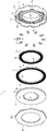
- FIG. 1 is a component development view showing the energy absorbing device according to the embodiment of the present invention.
- 2 is a component assembly diagram of the energy absorbing device shown in FIG. 1, wherein (A) is a plan view and (B) is a cross-sectional view taken along line BB in FIG. 2 (A).
- FIG. 2A the illustration of the first clutch disk and the second clutch disk is omitted for convenience of explanation.
- the energy absorbing device 1 is an energy absorbing device disposed between relatively rotating objects, and is connected to one object.
- a casing 2 an annular first clutch disk 3 that can be reciprocated in the direction of the rotation axis in the casing 2, and a reciprocating movement in the direction of the rotation axis in the casing 2 that is disposed inside the first clutch disk 3.
- An annular second clutch disk 4 an annular clutch plate 5 connected to the other object and having a contact surface facing both the first clutch disk 3 and the second clutch disk 4, and the first clutch disk 3
- a plurality of linear motion members 6 disposed so as to be capable of reciprocating in the radial direction between the second clutch disk 4 and the casing 2, and reciprocating the linear motion members 6.
- the casing 2 has a bottomed cylindrical shape that can accommodate the first clutch disk 3 and the second clutch disk 4 having a circular outer shape.
- the casing 2 has a double cylindrical shape having a cylindrical outer wall 21 and an inner wall 22.
- the illustrated shape of the casing 2 is merely an example, and is not limited to a cylindrical shape as long as the first clutch disc 3 and the second clutch disc 4 can be accommodated.
- the casing 2 has a rotational axis arranged on a concentric axis with respect to one of the relatively rotating objects.
- the casing 2 is fixed to one object by inserting a hollow portion formed by the inner wall 22 through a rotation shaft of the one object.
- the fixing method of the casing 2 is not limited to this structure,
- the center part (inner diameter part of the inner wall 22) of the casing 2 may be hollow, and may be solid.
- the casing 2 has a plurality of partition members 23 that divide the location of the linear motion member 6.
- the partition member 23 is a wall member connected to the outer wall 21 and the inner wall 22, and is formed in a substantially radial shape as indicated by a dotted line in FIG. Therefore, a plurality of concave and convex portions can be alternately formed in the circumferential direction of the casing 2, and the linear motion member 6 is accommodated in the concave portion 24 formed in the gap between the partition members 23.
- FIGS. 1 and 2A when ten linear motion members 6 are arranged, at least ten concave portions 24 are formed.
- the partition member 23 has a protruding portion 23 a that partitions the place where the first clutch disk 3 is placed and the place where the second clutch disk 4 is placed.
- the protrusion 23 a is formed at the intermediate portion of the partition member 23 along the inner edge of the first clutch disk 3 and the outer edge of the second clutch disk 4.
- the partition member 23 and the outer wall 21 form an accommodation space 23b for the first clutch disk 3 outside the projection 23a.
- the partition member 23 and the inner wall 22 accommodate the second clutch disk 4 inside the projection 23a.
- a space 23c is formed. As shown in the figure, a plurality of protrusions 23 a may be formed for one partition member 23.
- the first clutch disk 3 is an annular flat plate member accommodated in an accommodation space 23b formed by a plurality of partition members 23.
- the first clutch disk 3 has an engagement tooth 31 formed on the contact surface side with the clutch plate 5 and a protrusion 32 formed on the contact surface side with the partition member 23.
- the engaging teeth 31 are formed with valleys in the circumferential direction by a plurality of radial grooves formed on the surface of the first clutch disk 3.
- the protrusion 32 is formed at a position where it can be inserted into the recess 24 formed in the casing 2.
- the protrusion part 32 has the taper surface 32a formed so that the linear motion member 6 and sliding were possible. Further, as shown in FIG.
- the first clutch disc 3 may have a locking portion 33 that protrudes inward in the radial direction and is disposed in a gap between the protruding portions 23 a of the partition member 23. Such a locking portion 33 can suppress the circumferential rotation of the first clutch disc 3.
- the second clutch disk 4 is an annular flat plate member that is accommodated in an accommodation space 23c formed by a plurality of partition members 23.
- the second clutch disk 4 has engagement teeth 41 formed on the contact surface side with the clutch plate 5 and protrusions 42 formed on the contact surface side with the partition member 23.
- the engaging teeth 41 are formed with valleys in the circumferential direction by a plurality of radial grooves formed on the surface of the second clutch disk 4.
- the protrusion 42 is formed at a position where it can be inserted into the recess 24 formed in the casing 2.
- the projecting portion 42 has a tapered surface 42 a formed so as to be slidable with the linear motion member 6. Further, as shown in FIG.
- the second clutch disk 4 may have a locking portion 43 that protrudes inward in the radial direction and is disposed in a gap between the protruding portions 23 a of the partition member 23. Such a locking portion 43 can suppress the circumferential rotation of the second clutch disc 4.
- the clutch plate 5 is an annular flat plate member having a contact surface 50 facing the engagement teeth 31 of the first clutch disk 3 and the engagement teeth 41 of the second clutch disk 4. On the contact surface 50, engagement teeth 51 that can mesh with the engagement teeth 31 and 41 are formed. In the engaging teeth 51, peaks and valleys are formed in the circumferential direction by a plurality of radial grooves formed on the surface of the clutch plate 5 (see FIG. 8). The engaging teeth 51 may be separated into a portion facing the engaging teeth 31 and a portion facing the engaging teeth 41 as shown in FIG. In addition, the rotation axis of the clutch plate 5 is arranged on a concentric axis with respect to the other object that rotates relatively (an object that rotates relative to an object connected to the casing 2).
- the clutch plate 5 is connected to the other object by inserting the inner edge portion through the rotation shaft of the other object, and can be connected to the other object at the inner edge portion of the clutch plate 5 as shown in FIG. You may have the latching
- FIG. The method for fixing the clutch plate 5 is not limited to this configuration.
- the engagement teeth 31, 41, 51 are formed with teeth (or grooves) in the same phase, and the engagement teeth 31 of the first clutch disk 3 and the first engagement teeth 51 of the clutch plate 5 are formed.
- the engaging teeth 41 of the two-clutch disc 4 are formed so that they can mesh with each other.
- a configuration in which the other object that rotates relative to the engaging portion 52 of the clutch plate 5 is connected is illustrated, but the configuration is not limited thereto.
- the other relatively rotating object may be fixed to the clutch plate 5 by welding, bonding, screwing, or the like, and the locking portion 52 can be omitted as necessary.
- the clutch plate 5 is disposed in the casing 2 so as to be rotatable relative to the casing 2, and the casing 2 has a cover plate 25 that restricts the movement of the clutch plate 5 in the rotation axis direction.
- the cover plate 25 is an annular member that can be accommodated in the casing 2, for example, and has a plurality of protrusions 25 a on the outer periphery. Further, a notch 21 a into which the protrusion 25 a of the cover plate 25 can be inserted is formed at the edge of the outer wall 21 of the casing 2.
- the surface (back surface 53) opposite to the contact surface 50 of the clutch plate 5 is preferably formed so that the frictional resistance is reduced with respect to the inner surface of the cover plate 25 fixed to the casing 2.
- the shape and fixing method of the cover plate 25 are not limited to the illustrated configuration.
- the cover plate 25 may be a disk shape or a lid member that can be screwed into the casing 2. Alternatively, it may be configured to be fixed to the inner wall 22.
- the linear motion member 6 has a thin block shape that can be accommodated in the recess 24 of the casing 2 and has tapered surfaces 61 and 62 formed at both ends in the moving direction.
- the tapered surface 61 is formed on the radially outer side of the linear motion member 6, and is formed so as to be able to contact the tapered surface 32 a formed on the protrusion 32 of the first clutch disk 3.
- the tapered surface 62 is formed on the radially inner side of the linear motion member 6 and is formed so as to be able to come into contact with the tapered surface 42 a formed on the protrusion 42 of the second clutch disk 4.
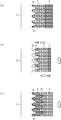
- FIG. 3 is a diagram showing the operation of the energy absorbing device when the clutch plate rotates, where (A) is the first clutch disk engaged state, (B) is the relative rotation start state, and (C) is The second clutch disk engagement state is shown.
- FIGS. 4A and 4B are diagrams illustrating the operation of the energy absorbing device when the casing rotates, where FIG. 4A is a first clutch disk engaged state, FIG. 4B is a relative rotation start state, and FIG. 4C is a second clutch disk. The engaged state is shown.
- FIG. 5 is a diagram showing the relationship between the rotational speed of the relative rotation and the load generated by the energy absorbing device.
- FIGS. 3A to 3C show the operation when the casing 2 is fixed and the clutch plate 5 rotates
- FIGS. 4A to 4C are as follows.
- the operation when the clutch plate 5 is fixed and the casing 2 rotates is shown.
- 3A to 4C the illustration of the linear motion member 6 is omitted.
- the energy absorption amount (N) can be varied with respect to the relative rotational speed (m / s), and the rotational speed.
- the rotation speed is low, the energy absorption amount can be reduced, and when the rotation speed is high, the energy absorption amount can be increased.
- the energy absorption amount with respect to the rotation speed is illustrated by a quadratic curve in which the energy absorption amount increases with an increase in the rotation speed acceleration, but the energy absorption amount increases with the increase in the rotation speed. It may have a proportional relationship that increases.
- the energy absorbing device 1 since only one side of the first clutch disk 3 and the second clutch disk 4 is engaged with the clutch plate 5, the first clutch disk 3, the strength of the second clutch disk 4 and the clutch plate 5 can be easily improved, and the durability of the energy absorbing device 1 can be improved.
- the plate thickness of the first clutch disk 3, the second clutch disk 4 and the clutch plate 5 can be easily changed, or the back surfaces of the first clutch disk 3, the second clutch disk 4 and the clutch plate 5 can be easily reinforced. can do.
- FIG. 6 is an overall configuration diagram showing the seat belt device according to the present embodiment.
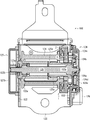
- FIG. 7 is a cross-sectional view of the seat belt retractor according to the present embodiment.
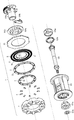
- FIG. 8 is a part development view showing the shaft unit of the seat belt retractor shown in FIG.
- symbol is attached
- the seat belt device 100 shown in FIG. 6 is provided with a webbing 101 that restrains an occupant (not shown) to the seat S, a seat belt retractor 102 that winds the webbing 101, and a webbing 101 that is provided on the vehicle body side.
- a guide anchor 103, a belt anchor 104 that fixes the webbing 101 to the vehicle body side, a buckle 105 disposed on the side surface of the seat S, and a tongue 106 disposed on the webbing 101 are provided.
- the illustrated seat belt device 100 is a so-called passenger seat belt device, and a pillar P is often disposed at a position adjacent to the seat S.
- the seat belt retractor 102 is disposed in the pillar P
- the guide anchor 103 is disposed on the surface of the pillar P.
- the occupant can be restrained to the seat S by the webbing 101 by pulling out the webbing 101 and fitting the tongue 106 to the buckle 105.
- the configuration of the seat belt device 100 other than the seat belt retractor 102 described above is the same as that of the conventional seat belt device, and thus detailed description thereof is omitted here.
- the seat belt device 100 is not limited to the one for the passenger seat, and may be a seat belt device for a driver's seat or a seat belt device for a rear seat. In the seat belt device for the rear seat, the guide anchor 103 may be omitted.
- the seat belt retractor 102 shown in FIG. 7 includes a spool 121 that winds up a webbing (not shown) that restrains an occupant, a base frame 122 that rotatably holds the spool 121, and a base frame 122 or a base frame 122. And an energy absorbing device 1 disposed between the spool 121 and the component fixed to the spool.
- the shaft unit shown in FIG. 8 is obtained by omitting the base frame 122, the spring means 123 described later, a part of the lock mechanism 124 described later, and the acceleration sensor 126 in the seat belt retractor 102 shown in FIG. is there.
- the seat belt retractor 102 includes a substantially U-shaped or square U-shaped base frame 122 that rotatably supports the spool 121, spring means 123 disposed at one end of the spool 121, and the other end of the spool 121. It has a lock mechanism 124 to be arranged, a torsion bar 125 inserted through the center of the spool 121, and an acceleration sensor 126 for detecting the acceleration of the vehicle.
- the seatbelt retractor 102 concerning this embodiment does not have a pretensioner. It may or may not have.
- the spring means 123 has a spring core 123a that forms the axis of a spiral spring (not shown), and a spring cover 123b that houses the spiral spring.
- One end of a torsion bar 125 is connected to the spring core 123a.
- the torsion bar 125 is rotatably supported by a bearing 122 a disposed on the base frame 122.
- a push nut 122b for preventing removal may be disposed outside the bearing 122a.
- the locking mechanism 124 includes a locking base 124a disposed at an end portion of the torsion bar 125, a pawl 124b disposed to be swingable on the locking base 124a, and an end of the torsion bar 125 so as to be adjacent to the outside of the locking base 124a.
- a lock gear 124c disposed in the section, a flywheel 124d swingably disposed on the lock gear 124c, and a retainer 124e that accommodates these components and rotatably supports the torsion bar 125. Yes.
- the acceleration sensor 126 is disposed adjacent to the lock mechanism 124, and has a protrusion that can engage with teeth formed on the outer periphery of the lock gear 124c when detecting acceleration generated in the vehicle due to a vehicle collision or the like. Yes.
- the flywheel 124d is configured to be able to swing the pawl 124b as it swings.
- the rocked pawl 124 b protrudes in the outer diameter direction of the locking base 124 a and engages with teeth formed in the opening of the base frame 122.
- the locking base 124 a is fixed to the base frame 122 by the engagement of the pawl 124 b.
- the spool 121 connected to the webbing rotates relative to the locking base 124a.
- the energy generated in the webbing due to the torsion bar 125 being twisted is absorbed.
- the maximum torsional rotation speed of the torsion bar 125 is defined by a stopper 125a inserted into the outer periphery of the shaft portion of the locking base 124a, and the torsion bar 125 is prevented from being broken.
- a collar 125b for preventing rattling may be disposed between the stopper 125a and the spool 121.
- the description of the seat belt retractor 102 so far has substantially the same configuration as that of the conventional seat belt retractor described in, for example, Japanese Patent Application Laid-Open No. 2012-30636, and the detailed description thereof is omitted. To do.
- the seat belt retractor 102 includes a fixing ring 102a fixed to the locking base 124a, and the energy absorbing device 1 disposed between the spool 121 and the fixing ring 102a.
- the casing 2 of the energy absorbing device 1 is fixed on the concentric shaft with respect to the spool 121, and the clutch plate 5 is fixed on the concentric shaft with respect to the fixing ring 102a.
- the engagement tooth 52 is formed in the inner peripheral part of the clutch plate 5, and the external tooth which engages with the engagement tooth 52 of the clutch plate 5 is formed in the fixing ring 102a. Has been.
- the locking mechanism 124 when the locking mechanism 124 is operated to cause a relative rotational movement between the locking base 124a and the spool 121, the clutch plate 5 and the casing 2 cause a relative rotational movement. .
- the energy absorbing device 1 operates and can absorb the energy generated in the webbing.
- the energy absorbing device 1 is configured to operate simultaneously with the operation of the torsion bar 125.
- the burden on the energy absorbing device 1 can be reduced, and the energy absorbing device 1 can be reduced in size and weight.
- the seat belt retractor 102 having only the conventional torsion bar operates uniformly when a predetermined load is generated even in the case of a passenger with a large physique and a passenger with a small physique.
- a passenger with a large physique is on board
- the upper body of the occupant moves forward due to a vehicle collision or the like
- it is difficult to decelerate and an occupant with a small physique is on board
- the amount of energy absorption can be increased or decreased according to the relative rotational speed, so that a sensor that determines the physique of the occupant Etc., the amount of energy absorption can be increased or decreased in accordance with the webbing withdrawal speed corresponding to the occupant's physique.
- the torsion bar 125 may be omitted.
- a metal or resin shaft (not shown) having substantially the same shape as the torsion bar 125 is prepared, and the shaft is configured so as to be freely rotatable with respect to the bearing 122a. Even when 124 is activated, the spool 121 can be rotated relative to the shaft. Even in such a configuration, the energy absorbing device 1 can be operated by the relative rotational movement of the locking base 124 a and the spool 121.
- the present invention is not limited to the above-described embodiment.
- the casing 2 may be fixed to the locking base 124a, and the clutch plate 5 may be fixed to the spool 121.
- Various modifications are possible without departing from the spirit of the present invention. Of course, it can be changed.
Landscapes
- Engineering & Computer Science (AREA)
- Mechanical Engineering (AREA)
- General Engineering & Computer Science (AREA)
- Physics & Mathematics (AREA)
- Acoustics & Sound (AREA)
- Aviation & Aerospace Engineering (AREA)
- Automotive Seat Belt Assembly (AREA)
- Vibration Dampers (AREA)
Abstract
相対的に回転運動する物体間において回転速度の増減に応じてエネルギー吸収量を変動させることができるとともに、耐久性を向上させることができる、エネルギー吸収装置、シートベルトリトラクタ及びシートベルト装置を提供する。 一方の物体に接続されるケーシング2と、ケーシング2内に配置される環状の第一クラッチディスク3と、ケーシング2内に配置される環状の第二クラッチディスク4と、他方の物体に接続されるクラッチプレート5と、第一クラッチディスク3及び第二クラッチディスク4とケーシング2との間に径方向に往復動可能に配置された複数の直動部材6と、を備え、直動部材6を往復動させることにより、第一クラッチディスク3及び第二クラッチディスク4をクラッチプレート5に交互に接触するように移動させるようにした。
Description
本発明は、エネルギー吸収装置、シートベルトリトラクタ及びシートベルト装置に関し、特に、相対的に回転運動する物体間に配置されるエネルギー吸収装置、該エネルギー吸収装置を備えたシートベルトリトラクタ及び該シートベルトリトラクタを備えたシートベルト装置に関する。
例えば、帯状や紐状の長尺物の巻き取り装置(巻き戻し機能も含む)において、長尺物を巻き取る巻胴(ドラムやスプールと称されることもある)は、該巻胴を回転可能に支持する支持手段に対して相対的に回転運動している。かかる相対運動をする装置において長尺物が伸びきった場合や巻き取り又は巻き戻し中に巻胴が停止した場合には、装置や長尺物に大きな荷重がかかることから、相対運動する物体間にエネルギー吸収装置を配置することが好ましい。かかる巻き取り装置の一例としては、シートベルト装置に使用されるシートベルトリトラクタが代表的である(例えば、特許文献1又は特許文献2参照)。
特許文献1には、相対的に回転運動する巻取ドラムとラチェットギヤとの間にトーションバーとワイヤとを配置したシートベルトリトラクタが開示されている。かかるシートベルトリトラクタによれば、トーションバーの捩り変形及びワイヤの摺動変形により巻取ドラムとラチェットギヤとの間に生じ得るエネルギーを吸収することができるとともに、ワイヤを摺動変形させるために必要な引き出し荷重を異ならせることによってエネルギー吸収特性を変化させることができる。
特許文献2には、相対的に回転運動する物体間にリングディスク(1,3)と揺動部材(2)とを配置した車両用フォースリミッタ装置が開示されている。かかる装置によれば、リングディスク(1,3)に対して揺動部材(2)が相対回転する際に、揺動部材(2)に形成された突起(5)がリングディスク(1,3)に形成された突起(7,8)に交互に揺動しながら接触することにより、相対的に回転運動する物体間に生じるエネルギーを吸収することができる。特に、本装置では、揺動部材(2)の回転速度によって運動エネルギーが変化し、揺動部材(2)の回転速度が増加するに連れてエネルギー吸収量を増大させることができる。
ところで、上述した特許文献1や特許文献2に記載されたようなエネルギー吸収装置を備えたシートベルトリトラクタを有するシートベルト装置では、同一の車両であっても、男性や女性、大柄な体格の人や小柄な体格の人等、種々の体格を有する乗員がシートに着座することとなる。したがって、同一のシートベルト装置であっても、車両衝突時にウェビングやリトラクタにかかる荷重が変動することとなる。
この変動荷重に対応するためには、車両に乗員の体格を判断するセンサを配置したり、異なる荷重に対応可能なエネルギー吸収装置を配置したりしなければならない。なお、かかる事象は、シートベルトリトラクタに限定されるものではなく、例えば、厚さや種類の異なる長尺物(織物、甲板等)を巻き取る巻き取り装置においても生じ得る。
しかしながら、特許文献1に記載されたエネルギー吸収装置では、ワイヤとトーションバーの二段階にエネルギー吸収特性を変更することができるものの、無段階にエネルギー吸収特性を変更することができない。
特許文献2に記載されたエネルギー吸収装置では、揺動部材の回転速度に応じてエネルギー吸収量を変更することができ、種々の体格の乗員に対応させることができるものの、揺動部材がリングディスク間を往復移動することから、揺動部材の全周に生じる荷重が不均一となった場合には、応力集中が生じて揺動部材が破損しやすいという問題がある。また、揺動部材が回転しながら揺動することから、リングディスクからの反力により撓みを生じる可能性があり、金属疲労が蓄積しやすく、耐久性に劣るという問題もある。
本発明はかかる問題点に鑑み創案されたものであり、相対的に回転運動する物体間において回転速度の増減に応じてエネルギー吸収量を変動させることができるとともに、耐久性を向上させることができる、エネルギー吸収装置、シートベルトリトラクタ及びシートベルト装置を提供することを目的とする。
本発明によれば、相対的に回転運動する物体間に配置されるエネルギー吸収装置であって、一方の物体に接続されるケーシングと、該ケーシング内で回転軸方向に往復動可能に配置される環状の第一クラッチディスクと、前記ケーシング内で回転軸方向に往復動可能かつ前記第一クラッチディスクの内側に配置される環状の第二クラッチディスクと、他方の物体に接続されるとともに前記第一クラッチディスク及び前記第二クラッチディスクの両方に対峙する接触面を有する環状のクラッチプレートと、前記第一クラッチディスク及び前記第二クラッチディスクと前記ケーシングとの間に径方向に往復動可能に配置された複数の直動部材と、を備え、前記直動部材を往復動させることにより、前記第一クラッチディスク及び前記第二クラッチディスクを前記クラッチプレートに交互に接触するように移動させるようにした、ことを特徴とするエネルギー吸収装置が提供される。
前記直動部材は、移動方向の両端に形成されたテーパ面を有し、前記第一クラッチディスク及び前記第二クラッチディスクは前記テーパ面に沿って摺動可能に形成された突起部を有していてもよい。
前記第一クラッチディスク及び前記第二クラッチディスクと前記クラッチプレートとの接触面には、それぞれ係合歯が形成されていてもよい。
前記ケーシングは、前記直動部材の配置場所を区画する複数の仕切部材を有していてもよい。また、前記仕切部材は、前記第一クラッチディスクの配置場所と前記第二クラッチディスクの配置場所とを区画する突起部を有していてもよい。さらに、前記第一クラッチディスクは、径方向内側に突出し前記仕切部材同士の間隙に配置される係止部を有し、前記第二クラッチディスクは、径方向外側に突出し前記仕切部材同士の間隙に配置される係止部を有していてもよい。
前記クラッチプレートは、前記ケーシングに対して相対的に回転可能に前記ケーシング内に配置され、前記ケーシングは、前記クラッチプレートの回転軸方向の移動を規制するカバープレートを有していてもよい。
また、本発明によれば、乗員を拘束するウェビングの巻き取りを行うスプールと、該スプールを回転可能に保持するベースフレームと、を備えたシートベルトリトラクタにおいて、前記ベースフレーム又は前記ベースフレームに固定される部品と前記スプールとの間に配置されたエネルギー吸収装置を備え、該エネルギー吸収装置は、上述した本発明に係るエネルギー吸収装置である、ことを特徴とするシートベルトリトラクタが提供される。
また、本発明によれば、乗員をシートに拘束するウェビングと、該ウェビングの巻き取りを行うシートベルトリトラクタと、前記ウェビングを車体側に固定するベルトアンカーと、前記シートの側面に配置されたバックルと、前記ウェビングに配置されたトングと、を備えたシートベルト装置において、前記シートベルトリトラクタは、上述した本発明に係るエネルギー吸収装置を備えたシートベルトリトラクタである、ことを特徴とするシートベルト装置が提供される。
上述した本発明に係るエネルギー吸収装置、シートベルトリトラクタ及びシートベルト装置によれば、相対回転するクラッチプレートに対して、直動部材を介して第一クラッチディスク及び第二クラッチディスクを回転軸方向に移動させて交互に接触させるようにしたことから、接触時に生じるエネルギーによって、相対回転する物体間に生じるエネルギーを吸収することができる。例えば、第一クラッチディスク及び第二クラッチディスクとクラッチプレートとの接触面にそれぞれ係合歯を形成することにより、クラッチプレートの相対回転速度の増減に応じて第一クラッチディスク及び第二クラッチディスクの往復動速度を増減させることができ、相対的に回転運動する物体間において回転速度の増減に応じてエネルギー吸収量を変動させることができる。
また、本発明によれば、回転する部品(クラッチプレート)と往復動する部品(第一クラッチディスク及び第二クラッチディスク)とに機能分担させたことにより、駆動時に生じる反力を各部品に分散させることができ、金属疲労の蓄積を低減することができ、耐久性を向上させることができる。さらに、第一クラッチディスク及び第二クラッチディスクの片面のみをクラッチプレートに係合させるようにしたことから、構造的に第一クラッチディスク、第二クラッチディスク及びクラッチプレートの強度を向上させやすく、エネルギー吸収装置の耐久性を向上させることができる。
以下、本発明の実施形態について図1~図8を用いて説明する。ここで、図1は、本発明の実施形態に係るエネルギー吸収装置を示す部品展開図である。図2は、図1に示したエネルギー吸収装置の部品組立図であり、(A)は平面図、(B)は図2(A)におけるB-B断面図、を示している。なお、図2(A)において、説明の便宜上、第一クラッチディスク及び第二クラッチディスクの図を省略してある。
本発明の実施形態に係るエネルギー吸収装置1は、図1及び図2に示したように、相対的に回転運動する物体間に配置されるエネルギー吸収装置であって、一方の物体に接続されるケーシング2と、ケーシング2内で回転軸方向に往復動可能に配置される環状の第一クラッチディスク3と、ケーシング2内で回転軸方向に往復動可能かつ第一クラッチディスク3の内側に配置される環状の第二クラッチディスク4と、他方の物体に接続されるとともに第一クラッチディスク3及び第二クラッチディスク4の両方に対峙する接触面を有する環状のクラッチプレート5と、第一クラッチディスク3及び第二クラッチディスク4とケーシング2との間に径方向に往復動可能に配置された複数の直動部材6と、を備え、直動部材6を往復動させることにより、第一クラッチディスク3及び第二クラッチディスク4をクラッチプレート5に交互に接触するように移動させるようにしたものである。
ケーシング2は、円形状の外形を有する第一クラッチディスク3及び第二クラッチディスク4を収容可能な有底の円筒形状を有している。また、ケーシング2は、円筒形状の外壁21及び内壁22を有する二重円筒形状を有している。なお、図示したケーシング2の形状は、単なる一例であり、第一クラッチディスク3及び第二クラッチディスク4を収容可能であれば、円筒形状に限定されるものでもない。また、ケーシング2は、相対回転する一方の物体に対して回転軸が同心軸上に配置される。例えば、ケーシング2は、内壁22により形成される中空部を一方の物体の回転軸に挿通することにより一方の物体に固定される。なお、ケーシング2の固定方法はかかる構成に限定されるものではなく、ケーシング2の中央部(内壁22の内径部)は、中空であってもよいし、中実であってもよい。
ケーシング2は、直動部材6の配置場所を区画する複数の仕切部材23を有している。仕切部材23は、外壁21及び内壁22に連結された壁部材であり、図2(A)に点線で示したように、略放射状に形成されている。したがって、ケーシング2の周方向に交互に複数の凹凸部を形成することができ、仕切部材23同士の間隙に形成される凹部24に直動部材6が収容される。例えば、図1及び図2(A)に示したように、10個の直動部材6を配置する場合には、少なくとも10個の凹部24が形成される。なお、吸収するエネルギーの大小に応じて、直動部材6の個数を変更することができるように、予め多数の凹部24をケーシング2に形成しておくようにしてもよい。
また、仕切部材23は、第一クラッチディスク3の配置場所と第二クラッチディスク4の配置場所とを区画する突起部23aを有している。突起部23aは、仕切部材23の中間部に第一クラッチディスク3の内縁及び第二クラッチディスク4の外縁に沿うように形成される。そして、仕切部材23と外壁21とにより突起部23aの外側に第一クラッチディスク3の収容空間23bが形成され、仕切部材23と内壁22とにより突起部23aの内側に第二クラッチディスク4の収容空間23cが形成される。なお、図示したように、一つの仕切部材23に対して、複数の突起部23aを形成するようにしてもよい。
第一クラッチディスク3は、複数の仕切部材23によって形成される収容空間23bに収容される環状の平板部材である。第一クラッチディスク3は、クラッチプレート5との接触面側に形成された係合歯31と、仕切部材23との接触面側に形成された突起部32と、を有している。係合歯31は、第一クラッチディスク3の表面に形成された複数の放射状の溝によって、周方向に山谷が形成される。突起部32は、図2(B)及び後述する図8に示したように、ケーシング2に形成された凹部24に挿入可能な位置に形成されている。また、突起部32は、直動部材6と摺動可能に形成されたテーパ面32aを有している。また、図1に示したように、第一クラッチディスク3は、径方向内側に突出し仕切部材23の突起部23a同士の間隙に配置される係止部33を有していてもよい。かかる係止部33により、第一クラッチディスク3の周方向の回転を抑制することができる。
第二クラッチディスク4は、複数の仕切部材23によって形成される収容空間23cに収容される環状の平板部材である。第二クラッチディスク4は、クラッチプレート5との接触面側に形成された係合歯41と、仕切部材23との接触面側に形成された突起部42と、を有している。係合歯41は、第二クラッチディスク4の表面に形成された複数の放射状の溝によって、周方向に山谷が形成される。突起部42は、図2(B)及び後述する図8に示したように、ケーシング2に形成された凹部24に挿入可能な位置に形成されている。また、突起部42は、直動部材6と摺動可能に形成されたテーパ面42aを有している。また、図1に示したように、第二クラッチディスク4は、径方向内側に突出し仕切部材23の突起部23a同士の間隙に配置される係止部43を有していてもよい。かかる係止部43により、第二クラッチディスク4の周方向の回転を抑制することができる。
クラッチプレート5は、第一クラッチディスク3の係合歯31及び第二クラッチディスク4の係合歯41と対峙する接触面50を有する環状の平板部材である。接触面50には、係合歯31,41と噛合可能な係合歯51が形成されている。係合歯51は、クラッチプレート5の表面に形成された複数の放射状の溝によって、周方向に山谷が形成される(図8参照)。係合歯51は、後述する図8に示したように、係合歯31に対峙する部分と係合歯41に対峙する部分とに分離していてもよい。また、クラッチプレート5は、相対回転する他方の物体(ケーシング2に接続される物体と相対的に回転運動する物体)に対して回転軸が同心軸上に配置される。例えば、クラッチプレート5は、内縁部を他方の物体の回転軸に挿通することにより他方の物体に接続され、図1に示したように、クラッチプレート5の内縁部に他方の物体に接続可能な係止部52を有していてもよい。なお、クラッチプレート5の固定方法はかかる構成に限定されるものではない。
係合歯31,41,51は、例えば、同位相に歯(又は溝)が形成されており、クラッチプレート5の係合歯51に対して、第一クラッチディスク3の係合歯31及び第二クラッチディスク4の係合歯41が噛み合うことができるように形成されている。本実施形態では、クラッチプレート5の係止部52に、相対回転する他方の物体を接続する構成を図示しているが、かかる構成に限定されるものではない。例えば、相対回転する他方の物体をクラッチプレート5に、溶接、接着、螺合等によって固定するようにしてもよく、必要に応じて係止部52は省略することができる。
また、クラッチプレート5は、ケーシング2に対して相対的に回転可能にケーシング2内に配置され、ケーシング2は、クラッチプレート5の回転軸方向の移動を規制するカバープレート25を有している。カバープレート25は、例えば、ケーシング2内に収容可能な環状部材であり、外周部に複数の突起25aを有している。また、ケーシング2の外壁21の縁部には、カバープレート25の突起25aを挿入可能な切欠21aが形成されている。
また、クラッチプレート5の接触面50に対する反対側の面(裏面53)は、ケーシング2に固定されたカバープレート25の内面に対して摩擦抵抗が少なくなるように形成されていることが好ましい。なお、カバープレート25の形状や固定方法は、図示した構成に限定されるものではなく、例えば、カバープレート25は円盤形状であってもよいし、ケーシング2に螺合可能な蓋部材であってもよいし、内壁22に固定可能な構成であってもよい。
直動部材6は、ケーシング2の凹部24に収容可能な薄板のブロック形状を有し、移動方向の両端に形成されたテーパ面61,62を有している。テーパ面61は、直動部材6の径方向外側に形成されており、第一クラッチディスク3の突起部32に形成されたテーパ面32aと接触可能に形成されている。テーパ面62は、直動部材6の径方向内側に形成されており、第二クラッチディスク4の突起部42に形成されたテーパ面42aと接触可能に形成されている。
したがって、直動部材6が、ケーシング2の凹部24内で径方向外側に移動すると、テーパ面61が第一クラッチディスク3の突起部32に形成されたテーパ面32aと接触して摺動し、第一クラッチディスク3をクラッチプレート5に向かって押し上げる。このとき、第二クラッチディスク4は、直動部材6の移動に伴ってケーシング2の仕切部材23側に移動可能となる。また、直動部材6が、ケーシング2の凹部24内で径方向内側に移動すると、テーパ面62が第二クラッチディスク4の突起部42に形成されたテーパ面42aと接触して摺動し、第二クラッチディスク4をクラッチプレート5に向かって押し上げる。このとき、第一クラッチディスク3は、直動部材6の移動に伴ってケーシング2の仕切部材23側に移動可能となる。
次に、上述したエネルギー吸収装置1の作用について、図3(A)~図5を参照しつつ説明する。ここで、図3は、クラッチプレートが回転する場合におけるエネルギー吸収装置の作用を示す図であり、(A)は第一クラッチディスク係合状態、(B)は相対回転開始状態、(C)は第二クラッチディスク係合状態、を示している。図4は、ケーシングが回転する場合におけるエネルギー吸収装置の作用を示す図であり、(A)は第一クラッチディスク係合状態、(B)は相対回転開始状態、(C)は第二クラッチディスク係合状態、を示している。図5は、相対回転の回転速度とエネルギー吸収装置により生じる荷重との関係を示す図である。
図3(A)~(C)に示した説明図は、ケーシング2が固定され、クラッチプレート5が回転する場合の作用を示し、図4(A)~(C)に示した説明図は、クラッチプレート5が固定され、ケーシング2が回転する場合の作用を示している。なお、図3(A)~図4(C)の各図において、直動部材6の図を省略してある。
図3(A)に示したように、クラッチプレート5の係合歯51に第一クラッチディスク3の係合歯31が係合している状態を想定する。この状態から、クラッチプレート5が図の上方向に回転した場合、第一クラッチディスク3及び第二クラッチディスク4は回転しないようにケーシング2に収容されていることから、第一クラッチディスク3及び第二クラッチディスク4とクラッチプレート5との間に相対的な回転運動が生じる。
そして、図3(B)に示したように、クラッチプレート5の係合歯51の移動に伴って、第一クラッチディスク3の係合歯31は、クラッチプレート5から離隔する方向に押し出される。また、同時に、直動部材6の作用によって、第一クラッチディスク3がクラッチプレート5から離隔する方向に押し出されるに伴って、第二クラッチディスク4がクラッチプレート5に接近する方向に移動する。
最終的に、第一クラッチディスク3の係合歯31とクラッチプレート5の係合歯51との係合が解除された状態では、図3(C)に示したように、第二クラッチディスク4の係合歯41がクラッチプレート5の係合歯51に係合することとなる。そして、クラッチプレート5の回転に伴って、第一クラッチディスク3及び第二クラッチディスク4は、交互に回転軸方向に往復動され、係合歯31,41は、係合歯51に交互に係合することとなる。
次に、図4(A)に示したように、クラッチプレート5の係合歯51に第一クラッチディスク3の係合歯31が係合している状態を想定する。この状態から、ケーシング2が図の上方向に回転した場合、第一クラッチディスク3及び第二クラッチディスク4は回転しないようにケーシング2に収容されていることから、第一クラッチディスク3及び第二クラッチディスク4とクラッチプレート5との間に相対的な回転運動が生じる。
そして、クラッチプレート5の軸方向の移動は規制されていることから、図4(B)に示したように、第一クラッチディスク3の係合歯31の移動に伴って、第一クラッチディスク3の係合歯31は、クラッチプレート5から離隔する方向に押し出される。また、同時に、直動部材6の作用によって、第一クラッチディスク3がクラッチプレート5から離隔する方向に押し出されるに伴って、第二クラッチディスク4がクラッチプレート5に接近する方向に移動する。
最終的に、第一クラッチディスク3の係合歯31とクラッチプレート5の係合歯51との係合が解除された状態では、図4(C)に示したように、第二クラッチディスク4の係合歯41がクラッチプレート5の係合歯51に係合することとなる。そして、ケーシング2の回転に伴って、第一クラッチディスク3及び第二クラッチディスク4は、交互に回転軸方向に往復動され、係合歯31,41は、係合歯51に交互に係合することとなる。
上述した本実施形態に係るエネルギー吸収装置1の構成によれば、クラッチプレート5とケーシング2との相対的な回転速度が高速になると、それに伴って第一クラッチディスク3及び第二クラッチディスク4の往復動する速度も高速となり、第一クラッチディスク3及び第二クラッチディスク4の運動エネルギー(E=1/2・mv2)が増大する。
したがって、第一クラッチディスク3及び第二クラッチディスク4がクラッチプレート5に接触したときの垂直抗力Nが増大し、係合歯31,41と係合歯51との間に生じる摩擦力(F=μN)が大きくなる。また、第一クラッチディスク3及び第二クラッチディスク4の往復動によってケーシング2の壁面との間に生じる摩擦力も大きくなる。その結果、クラッチプレート5の相対的な回転運動によって生じる運動エネルギーを、第一クラッチディスク3及び第二クラッチディスク4の往復動によって摩擦力に変換することができ、クラッチプレート5の運動エネルギーを吸収することができる。
特に、本実施形態に係るエネルギー吸収装置1では、図5に示したように、相対的な回転速度(m/s)に対して、エネルギー吸収量(N)を変動させることができ、回転速度が遅い場合にはエネルギー吸収量を小さくすることができ、回転速度が速い場合にはエネルギー吸収量を大きくすることができる。なお、図5では、回転速度に対するエネルギー吸収量は、回転速度の加速度の増加に伴ってエネルギー吸収量が増大する二次曲線により図示しているが、回転速度の増加に伴ってエネルギー吸収量が増大する比例関係を有していてもよい。
また、本実施形態に係るエネルギー吸収装置1では、第一クラッチディスク3及び第二クラッチディスク4の片面のみをクラッチプレート5に係合させるようにしたことから、構造的に第一クラッチディスク3、第二クラッチディスク4及びクラッチプレート5の強度を向上させやすく、エネルギー吸収装置1の耐久性を向上させることができる。例えば、第一クラッチディスク3、第二クラッチディスク4及びクラッチプレート5の板厚を容易に変更したり、第一クラッチディスク3、第二クラッチディスク4及びクラッチプレート5の背面を容易に補強したりすることができる。
次に、上述したエネルギー吸収装置1を備えたシートベルトリトラクタ及びシートベルト装置について、図6~図8を参照しつつ説明する。ここで、図6は、本実施形態に係るシートベルト装置を示す全体構成図である。図7は、本実施形態に係るシートベルトリトラクタの断面図である。図8は、図7に示したシートベルトリトラクタのシャフトユニットを示す部品展開図である。なお、上述した実施形態に係るエネルギー吸収装置1と同じ構成部品については、同じ符号を付して重複した説明を省略する。
図6に示したシートベルト装置100は、乗員(図示せず)をシートSに拘束するウェビング101と、ウェビング101の巻き取りを行うシートベルトリトラクタ102と、車体側に設けられウェビング101を案内するガイドアンカー103と、ウェビング101を車体側に固定するベルトアンカー104と、シートSの側面に配置されたバックル105と、ウェビング101に配置されたトング106と、を備えている。
図示したシートベルト装置100は、いわゆる助手席用のシートベルト装置であり、シートSと隣接した位置にピラーPが配置されていることが多い。そして、例えば、シートベルトリトラクタ102はピラーP内に配置されており、ガイドアンカー103はピラーPの表面に配置されている。かかるシートベルト装置100では、ウェビング101を引き出してトング106をバックル105に嵌着することにより、ウェビング101で乗員をシートSに拘束することができる。
なお、上述したシートベルト装置100のシートベルトリトラクタ102以外の構成については、従来のシートベルト装置と同様の構成であるため、ここでは詳細な説明を省略する。また、シートベルト装置100は、助手席用のものに限定されず、運転席用のシートベルト装置であってもよいし、後部座席用のシートベルト装置であってもよい。後部座席用のシートベルト装置では、ガイドアンカー103を省略するようにしてもよい。
図7に示したシートベルトリトラクタ102は、乗員を拘束するウェビング(図示せず)の巻き取りを行うスプール121と、スプール121を回転可能に保持するベースフレーム122と、ベースフレーム122又はベースフレーム122に固定される部品とスプール121との間に配置されたエネルギー吸収装置1と、を備えている。なお、図8に示したシャフトユニットは、図7に示したシートベルトリトラクタ102のうち、ベースフレーム122、後述するスプリング手段123、後述するロック機構124の一部及び加速度センサ126を省略したものである。
シートベルトリトラクタ102は、スプール121を回転可能に支持する略コ字状又は角型のU字状のベースフレーム122と、スプール121の一端に配置されるスプリング手段123と、スプール121の他端に配置されるロック機構124と、スプール121の中心部に挿通されたトーションバー125と、車両の加速度を検知する加速度センサ126と、を有している。なお、車両衝突時等にウェビングを瞬間的に巻き取って乗員とウェビングとの隙間を消失させるプリテンショナの図は省略してあるが、本実施形態に係るかかるシートベルトリトラクタ102は、プリテンショナを有していてもよいし、有していなくてもよい。
スプリング手段123は、スパイラルスプリング(図示せず)の軸心を形成するスプリングコア123aと、スパイラルスプリングを収容するスプリングカバー123bと、を有している。スプリングコア123aには、トーションバー125の一端が接続されている。トーションバー125は、ベースフレーム122に配置されたベアリング122aにより回転可能に支持されている。なお、ベアリング122aの外側には抜け防止用のプッシュナット122bが配置されていてもよい。
ロック機構124は、トーションバー125の端部に配置されるロッキングベース124aと、ロッキングベース124aに揺動可能に配置されたパウル124bと、ロッキングベース124aの外側に隣接するようにトーションバー125の端部に配置されるロックギア124cと、ロックギア124cに揺動可能に配置されたフライホイール124dと、これらの部品を収容するとともにトーションバー125を回転可能に支持するリテーナ124eと、を有している。
加速度センサ126は、ロック機構124と隣接して配置されており、車両の衝突等により車両に生じた加速度を検知するとロックギア124cの外周に形成された歯と係合可能な突起を有している。
加速度センサ126が車両の衝突等により車両に生じた加速度を検知すると、ロックギア124cの回転を抑制し、それに伴ってフライホイール124dが揺動する。フライホイール124dは、自身の揺動に伴ってパウル124bを揺動させることができるように構成されている。揺動されたパウル124bは、ロッキングベース124aの外径方向に突出し、ベースフレーム122の開口部に形成された歯と係合する。このパウル124bの係合によって、ロッキングベース124aはベースフレーム122に固定された状態となる。
ロック機構124が作動した状態で、さらにウェビングが引き出されて所定の荷重が生じた場合、ウェビングに接続されたスプール121はロッキングベース124aに対して相対的に回転運動することとなる。このとき、トーションバー125が捻れることによってウェビングに生じたエネルギーを吸収する。なお、トーションバー125の最大捻れ回転数は、ロッキングベース124aの軸部の外周に挿嵌されたストッパ125aにより規定され、トーションバー125の断裂が抑制される。また、ストッパ125aとスプール121との間にはガタツキ防止用のカラー125bが配置されていてもよい。
ここまでのシートベルトリトラクタ102に関する説明は、例えば、特開2012-30636号等に記載された従来のシートベルトリトラクタと実質的に同様の構成を有しており、これ以上の詳細な説明を省略する。
本実施形態に係るシートベルトリトラクタ102は、上述した構成に加えて、ロッキングベース124aに固定された固定リング102aと、スプール121と固定リング102aとの間に配置されたエネルギー吸収装置1と、を有している。図7に示したように、エネルギー吸収装置1のケーシング2はスプール121に対して同心軸上に固定されており、クラッチプレート5は固定リング102aに対して同心軸上に固定されている。なお、図8に示したように、クラッチプレート5の内周部には係合歯52が形成されており、固定リング102aにはクラッチプレート5の係合歯52と係合する外歯が形成されている。
したがって、ロック機構124が作動して、ロッキングベース124aとスプール121との間に相対的な回転運動を生じた場合には、クラッチプレート5とケーシング2とは相対的な回転運動を生じることとなる。その結果、エネルギー吸収装置1が作動し、ウェビングに生じたエネルギーを吸収することができる。
ところで、図示したシートベルトリトラクタ102は、ベアリング122aに固定されたトーションバー125を有していることから、トーションバー125の作動と同時にエネルギー吸収装置1が作動するように構成されている。このように、エネルギー吸収装置1とトーションバー125とを併用することにより、エネルギー吸収装置1の負担を軽減することができ、エネルギー吸収装置1の小型化及び軽量化を図ることができる。
一般に、車両には、大柄の体格(男性等)や小柄な体格(女性や子供等)の乗員が乗車することとなる。従来のトーションバーのみを有するシートベルトリトラクタ102では、大柄な体格の乗員及び小柄な体格の乗員の場合であっても所定の荷重が生じた場合に一律に作動することとなる。例えば、大柄な体格の乗員が乗車している場合には、車両の衝突等によって、乗員の上体が前方に移動した際に減速しにくく、小柄な体格の乗員が乗車している場合には、車両の衝突等によって、乗員の上体が前方に移動した際に減速しやすい。
したがって、大柄な体格の乗員及び小柄な体格の乗員に合わせて、トーションバーの作動条件を設定しようとすれば、別途、乗員の体格を判断するセンサ等を搭載しなければならない。それに対して、上述した本実施形態に係るエネルギー吸収装置1を備えたシートベルトリトラクタ102では、相対的な回転速度に応じてエネルギー吸収量を増減させることができることから、乗員の体格を判断するセンサ等を搭載することなく、乗員の体格に応じたウェビングの引き出し速度に合わせてエネルギー吸収量を増減させることができる。
上述した実施形態では、トーションバー125を有する場合について説明したが、トーションバー125は省略することができる。例えば、トーションバー125と実質的に同一の形状を有する金属製や樹脂製のシャフト(図示せず)を用意するとともに、このシャフトをベアリング122aに対して自由回転可能に構成することにより、ロック機構124が作動した場合であっても、シャフトに対してスプール121を相対的に回転運動させることができる。かかる構成であっても、ロッキングベース124aとスプール121との相対的な回転運動によって、エネルギー吸収装置1を作動させることができる。
本発明は上述した実施形態に限定されず、例えば、ロッキングベース124aにケーシング2を固定し、スプール121にクラッチプレート5を固定するようにしてもよい等、本発明の趣旨を逸脱しない範囲で種々変更が可能であることは勿論である。
Claims (9)
- 相対的に回転運動する物体間に配置されるエネルギー吸収装置であって、
一方の物体に接続されるケーシングと、
該ケーシング内で回転軸方向に往復動可能に配置される環状の第一クラッチディスクと、
前記ケーシング内で回転軸方向に往復動可能かつ前記第一クラッチディスクの内側に配置される環状の第二クラッチディスクと、
他方の物体に接続されるとともに前記第一クラッチディスク及び前記第二クラッチディスクの両方に対峙する接触面を有する環状のクラッチプレートと、
前記第一クラッチディスク及び前記第二クラッチディスクと前記ケーシングとの間に径方向に往復動可能に配置された複数の直動部材と、を備え、
前記直動部材を往復動させることにより、前記第一クラッチディスク及び前記第二クラッチディスクを前記クラッチプレートに交互に接触するように移動させるようにした、
ことを特徴とするエネルギー吸収装置。 - 前記直動部材は、移動方向の両端に形成されたテーパ面を有し、前記第一クラッチディスク及び前記第二クラッチディスクは前記テーパ面に沿って摺動可能に形成された突起部を有する、ことを特徴とする請求項1に記載のエネルギー吸収装置。
- 前記第一クラッチディスク及び前記第二クラッチディスクと前記クラッチプレートとの接触面にはそれぞれ係合歯が形成されている、ことを特徴とする請求項1に記載のエネルギー吸収装置。
- 前記ケーシングは、前記直動部材の配置場所を区画する複数の仕切部材を有する、ことを特徴とする請求項1に記載のエネルギー吸収装置。
- 前記仕切部材は、前記第一クラッチディスクの配置場所と前記第二クラッチディスクの配置場所とを区画する突起部を有する、ことを特徴とする請求項4に記載のエネルギー吸収装置。
- 前記第一クラッチディスクは、径方向内側に突出し前記仕切部材同士の間隙に配置される係止部を有し、前記第二クラッチディスクは、径方向外側に突出し前記仕切部材同士の間隙に配置される係止部を有する、ことを特徴とする請求項5に記載のエネルギー吸収装置。
- 前記クラッチプレートは、前記ケーシングに対して相対的に回転可能に前記ケーシング内に配置され、前記ケーシングは、前記クラッチプレートの回転軸方向の移動を規制するカバープレートを有する、ことを特徴とする請求項1に記載のエネルギー吸収装置。
- 乗員を拘束するウェビングの巻き取りを行うスプールと、該スプールを回転可能に保持するベースフレームと、を備えたシートベルトリトラクタにおいて、
前記ベースフレーム又は前記ベースフレームに固定される部品と前記スプールとの間に配置されたエネルギー吸収装置を備え、該エネルギー吸収装置は、請求項1~7の何れか一項に記載のエネルギー吸収装置である、ことを特徴とするシートベルトリトラクタ。 - 乗員をシートに拘束するウェビングと、該ウェビングの巻き取りを行うシートベルトリトラクタと、前記ウェビングを車体側に固定するベルトアンカーと、前記シートの側面に配置されたバックルと、前記ウェビングに配置されたトングと、を備えたシートベルト装置において、
前記シートベルトリトラクタは、請求項1~7の何れか一項に記載のエネルギー吸収装置を備えたシートベルトリトラクタである、ことを特徴とするシートベルト装置。
Applications Claiming Priority (2)
| Application Number | Priority Date | Filing Date | Title |
|---|---|---|---|
| JP2014103958A JP6321450B2 (ja) | 2014-05-20 | 2014-05-20 | エネルギー吸収装置、シートベルトリトラクタ及びシートベルト装置 |
| JP2014-103958 | 2014-05-20 |
Publications (1)
| Publication Number | Publication Date |
|---|---|
| WO2015178162A1 true WO2015178162A1 (ja) | 2015-11-26 |
Family
ID=54553838
Family Applications (1)
| Application Number | Title | Priority Date | Filing Date |
|---|---|---|---|
| PCT/JP2015/062510 Ceased WO2015178162A1 (ja) | 2014-05-20 | 2015-04-24 | エネルギー吸収装置、シートベルトリトラクタ及びシートベルト装置 |
Country Status (2)
| Country | Link |
|---|---|
| JP (1) | JP6321450B2 (ja) |
| WO (1) | WO2015178162A1 (ja) |
Cited By (1)
| Publication number | Priority date | Publication date | Assignee | Title |
|---|---|---|---|---|
| CN112539237A (zh) * | 2020-12-14 | 2021-03-23 | 广州大学 | 一种双向惯性速度型阻尼器 |
Citations (2)
| Publication number | Priority date | Publication date | Assignee | Title |
|---|---|---|---|---|
| WO2010037460A2 (de) * | 2008-10-02 | 2010-04-08 | Autoliv Development Ab | Kraftbegrenzungseinrichtung für ein kraftfahrzeug |
| WO2012059166A1 (de) * | 2010-11-04 | 2012-05-10 | Autoliv Development Ab | Kraftbegrenzungseinrichtung für ein kraftfahrzeug |
-
2014
- 2014-05-20 JP JP2014103958A patent/JP6321450B2/ja active Active
-
2015
- 2015-04-24 WO PCT/JP2015/062510 patent/WO2015178162A1/ja not_active Ceased
Patent Citations (2)
| Publication number | Priority date | Publication date | Assignee | Title |
|---|---|---|---|---|
| WO2010037460A2 (de) * | 2008-10-02 | 2010-04-08 | Autoliv Development Ab | Kraftbegrenzungseinrichtung für ein kraftfahrzeug |
| WO2012059166A1 (de) * | 2010-11-04 | 2012-05-10 | Autoliv Development Ab | Kraftbegrenzungseinrichtung für ein kraftfahrzeug |
Cited By (1)
| Publication number | Priority date | Publication date | Assignee | Title |
|---|---|---|---|---|
| CN112539237A (zh) * | 2020-12-14 | 2021-03-23 | 广州大学 | 一种双向惯性速度型阻尼器 |
Also Published As
| Publication number | Publication date |
|---|---|
| JP6321450B2 (ja) | 2018-05-09 |
| JP2015217858A (ja) | 2015-12-07 |
Similar Documents
| Publication | Publication Date | Title |
|---|---|---|
| JP6145368B2 (ja) | シートベルトリトラクタ及びシートベルト装置 | |
| JP2015054651A (ja) | シートベルトリトラクタ及びシートベルト装置 | |
| US10207673B2 (en) | Seat belt retractor and seat belt device | |
| JP6266389B2 (ja) | エネルギー吸収装置、シートベルトリトラクタ及びシートベルト装置 | |
| JP6433696B2 (ja) | シートベルトリトラクタ及びシートベルト装置 | |
| JP2016196250A (ja) | シートベルトリトラクタ及びシートベルト装置 | |
| JP6401037B2 (ja) | エネルギー吸収装置、シートベルトリトラクタ及びシートベルト装置 | |
| JP6321450B2 (ja) | エネルギー吸収装置、シートベルトリトラクタ及びシートベルト装置 | |
| US10046731B2 (en) | Energy absorption apparatus, seatbelt retractor, and seatbelt apparatus | |
| JP6653133B2 (ja) | シートベルトリトラクタ及びシートベルト装置 | |
| JP6843182B2 (ja) | ウェビング巻取装置 | |
| JP2020175754A (ja) | リトラクタ及びシートベルト装置 | |
| JP6596274B2 (ja) | シートベルトリトラクタ及びシートベルト装置 | |
| JP6653137B2 (ja) | シートベルトリトラクタ及びシートベルト装置 | |
| JP6585432B2 (ja) | シートベルトリトラクタ及びシートベルト装置 | |
| JP6228480B2 (ja) | ウェビング巻取装置 | |
| JP2009255889A (ja) | ウエビング巻取装置 | |
| JP2019107922A (ja) | シートベルトリトラクタ及びシートベルト装置 | |
| JP2017193255A (ja) | ウェビング巻取装置 |
Legal Events
| Date | Code | Title | Description |
|---|---|---|---|
| 121 | Ep: the epo has been informed by wipo that ep was designated in this application |
Ref document number: 15796180 Country of ref document: EP Kind code of ref document: A1 |
|
| NENP | Non-entry into the national phase |
Ref country code: DE |
|
| 122 | Ep: pct application non-entry in european phase |
Ref document number: 15796180 Country of ref document: EP Kind code of ref document: A1 |