WO2015178132A1 - 焼結鉱の冷却機 - Google Patents
焼結鉱の冷却機 Download PDFInfo
- Publication number
- WO2015178132A1 WO2015178132A1 PCT/JP2015/061528 JP2015061528W WO2015178132A1 WO 2015178132 A1 WO2015178132 A1 WO 2015178132A1 JP 2015061528 W JP2015061528 W JP 2015061528W WO 2015178132 A1 WO2015178132 A1 WO 2015178132A1
- Authority
- WO
- WIPO (PCT)
- Prior art keywords
- cooling
- cooling tank
- suction chamber
- sintered ore
- duct
- Prior art date
Links
Images


Classifications
-
- B—PERFORMING OPERATIONS; TRANSPORTING
- B01—PHYSICAL OR CHEMICAL PROCESSES OR APPARATUS IN GENERAL
- B01D—SEPARATION
- B01D45/00—Separating dispersed particles from gases or vapours by gravity, inertia, or centrifugal forces
- B01D45/12—Separating dispersed particles from gases or vapours by gravity, inertia, or centrifugal forces by centrifugal forces
-
- C—CHEMISTRY; METALLURGY
- C22—METALLURGY; FERROUS OR NON-FERROUS ALLOYS; TREATMENT OF ALLOYS OR NON-FERROUS METALS
- C22B—PRODUCTION AND REFINING OF METALS; PRETREATMENT OF RAW MATERIALS
- C22B1/00—Preliminary treatment of ores or scrap
- C22B1/26—Cooling of roasted, sintered, or agglomerated ores
-
- F—MECHANICAL ENGINEERING; LIGHTING; HEATING; WEAPONS; BLASTING
- F27—FURNACES; KILNS; OVENS; RETORTS
- F27B—FURNACES, KILNS, OVENS, OR RETORTS IN GENERAL; OPEN SINTERING OR LIKE APPARATUS
- F27B21/00—Open or uncovered sintering apparatus; Other heat-treatment apparatus of like construction
-
- F—MECHANICAL ENGINEERING; LIGHTING; HEATING; WEAPONS; BLASTING
- F27—FURNACES; KILNS; OVENS; RETORTS
- F27D—DETAILS OR ACCESSORIES OF FURNACES, KILNS, OVENS, OR RETORTS, IN SO FAR AS THEY ARE OF KINDS OCCURRING IN MORE THAN ONE KIND OF FURNACE
- F27D15/00—Handling or treating discharged material; Supports or receiving chambers therefor
- F27D15/02—Cooling
-
- F—MECHANICAL ENGINEERING; LIGHTING; HEATING; WEAPONS; BLASTING
- F27—FURNACES; KILNS; OVENS; RETORTS
- F27D—DETAILS OR ACCESSORIES OF FURNACES, KILNS, OVENS, OR RETORTS, IN SO FAR AS THEY ARE OF KINDS OCCURRING IN MORE THAN ONE KIND OF FURNACE
- F27D17/00—Arrangements for using waste heat; Arrangements for using, or disposing of, waste gases
Definitions
- the present invention relates to a sinter cooler that cools the sinter.
- Patent Documents 1 and 2 As a cooling machine which cools the sintered ore sintered by the sintering machine, the thing as described in patent documents 1 and 2, for example is proposed. Both disclosed in Patent Documents 1 and 2 rotate an annular cooling tank in a plan view, and inject a sintered ore from the upper part of the cooling tank, and pass the air as a cooling gas into the cooling tank. The inner sintered ore is cooled, and the cooled ore is continuously discharged from the lower part of the cooling tank.
- Patent Document 2 sucks outside air as a cooling gas through an intake duct connected to the cooling tank, and passes the inside of the cooling tank, and exhaust gas is discharged through the exhaust gas recovery duct.
- air as cooling gas is sucked through the cooling tank in this way, since all exhaust gas containing dust passes through the exhaust gas recovery duct, providing the dust collecting equipment in this flow path does not increase the size of the entire device. The dust collection rate can be increased.
- the structure is such that air as the cooling gas passes through the gap between the sintered ores in the cooling tank twice. Therefore, the pressure loss in the cooling tank is also large, and the load of the blower for discharge becomes higher.
- it since it is configured to guide the air that has once passed through the lower part of the cooling tank to the upper part immediately afterwards, it is difficult to obtain high cooling efficiency as a whole, and it takes a long time to cool a predetermined amount of sintered ore. In other words, it may be necessary to enlarge the apparatus in order to increase the processing amount.
- the present invention has been made to solve such a problem, and realizes a compact structure that can easily collect dust while having high cooling efficiency of sinter ore and high-capacity processing.
- the aim is to provide a sinter cooler capable.
- a sinter ore cooler includes a charging unit for charging the sintered ore, and a discharge unit for discharging the cooled sintered ore provided below the charging unit.
- a cooling tank having an annular shape in plan view, and while the cooling tank is rotated, the sintered ore is introduced from the charging portion and blown to the sintered ore in the cooling tank and A cooler for cooling sintered ore, configured to cool the ore and discharge the cooled sintered ore from the discharge part,
- a gas passage portion is provided that allows gas to pass through while retaining the sintered ore on one side surface of the cooling tank, Of the other side surface of the cooling tank, a portion facing the gas passage portion is a ventilation portion that holds the sintered ore and allows air to pass through,
- the length in the height direction of the cooling region defined by the region sandwiched between the gas passage part and the ventilation part is 1 ⁇ 2 or more of the height of the cooling tank,
- the cooling zone has a thickness in the range of 1/6 to 1/4 of the height of the cooling tank,
- the cooling area of the cooling tank is characterized in that the thickness is in the range of 1/6 to 1/5 of the height.
- the cooling tank is such that the upper ends of both the inner peripheral side and the outer peripheral side of the cooling tank are more than the upper end of the gas passage part. It is characterized by being at a position 1.5 times higher than the thickness.
- the suction chamber includes two first suction chambers and a second suction chamber below the first suction chamber. Is divided into The intake duct is A first duct connected to the first suction chamber; A second duct connected to the second suction chamber, The suction device includes a first suction device that sucks gas through the first duct, and a second suction device that sucks gas through the second duct; Only the first duct is connected to the exhaust heat recovery unit.
- the gas passage portion is provided on a side surface on the inner peripheral side of the cooling tank
- the first duct includes a first longitudinally extending portion extending upward from an upper end of the cooling bath
- the second duct includes a second longitudinally extending portion extending upward from an upper end of the cooling bath
- the second longitudinally extending portion is disposed so as to extend upward in a central portion of the space surrounded by the annular cooling tank;
- a plurality of the first vertical extension portions are arranged so as to surround the second vertical extension portion in plan view. is there.
- the second duct extends in the lateral direction connecting the second longitudinally extending portion and the second suction chamber.
- the plurality of transverse conduits in plan view so that gas flowing from the plurality of transverse conduits into the second longitudinal extension forms a swirl flow in the second longitudinal extension.
- each center axis is connected to the second longitudinally extending portion in a state inclined with respect to the radial direction of the second longitudinally extending portion.
- the passage of dust by changing the flow direction of at least a part of the air flow from the gas passage portion side to the duct side in the suction chamber.
- a dust passage restricting member having a baffle plate for restricting the dust, and a dust collecting portion for collecting the dust whose passage is restricted by the dust passage restricting member.
- the dust passage restriction member is arranged such that a plurality of the baffle plates are separated from each other and inclined with respect to the thickness direction of the dust passage restriction member.
- the louver filter is characterized in that it is a louver filter.
- the dust passage restricting member may form a boundary between the space on the gas passage portion side and the space on the duct side in the suction chamber. It is characterized by being provided.
- the dust collecting part defines a space on the gas passage part side of the suction chamber forming wall forming the suction chamber.
- the portion to be tilted downward has a dust receiving portion positioned vertically below the dust passage restricting member, and a dust discharge mechanism is provided at the lower end of the dust receiving portion. is there.
- a gas passage portion is provided to pass the gas while retaining the sintered ore on one side surface of the annular cooling tank, and the portion facing the gas passage portion of the other side surface of the cooling tank is, It is a ventilation part that holds the sintered ore and allows air to pass, and the length in the height direction of the cooling area defined by the area sandwiched between the gas passage part and the ventilation part is 1 / of the height of the cooling tank. 2 or more, and the cooling region has a suction chamber forming wall that has a thickness in the range of 1/6 to 1/4 of the height of the cooling tank, and forms a suction chamber by covering the entire gas passage portion.
- An intake duct connected to the suction chamber so as to directly communicate with the entire suction chamber, and a suction device configured to generate a negative pressure in the intake duct for sucking the gas in the cooling tank And both side walls on the inner and outer peripheral sides of the cooling tank Since the upper end is at a position higher than the upper end of the cooling region by 1.2 times or more the thickness of the cooling region, the cooling efficiency of the sintered ore is good and the mass treatment is possible, but the heat recovery efficiency is high. It is possible to provide a sintered ore cooler capable of realizing an apparatus that facilitates dust collection with a compact configuration.
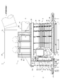
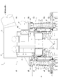
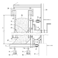
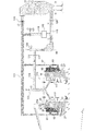
- FIG. 1 is a perspective view of a sintered ore cooler according to Embodiment 1 of the present invention. It is a side view including the partial cross section of the cooler of the sintered ore which concerns on Embodiment 1 of this invention. It is a longitudinal cross-sectional view of the cooler of the sintered ore which concerns on Embodiment 1 of this invention. It is an enlarged view of a partial cross section of the sintered ore cooler according to Embodiment 1 of the present invention. It is a schematic diagram which shows the whole structure of the cooler of the sintered ore which concerns on Embodiment 1 of this invention.
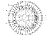
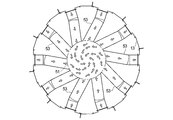
- FIG. 4 is a cross-sectional view taken along line AA in FIG. 3.
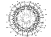
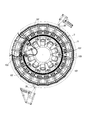
- FIG. 4 is a cross-sectional view taken along the line BB in FIG.
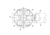
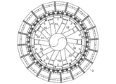
- FIG. 4 is a sectional view taken along the line CC in FIG. 3.
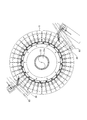
- FIG. 4 is a sectional view taken along the line DD in FIG. 3.
- FIG. 4 is a cross-sectional view taken along line EE in FIG. 3. It is operation
- FIG. 15 is a cross-sectional view taken along the line EE in FIG. 14, and partially includes a cross-sectional portion taken along the line FF shown in FIG. 14. It is a schematic diagram which shows the whole structure of the cooler of the sintered ore which concerns on Embodiment 2 of this invention. It is a schematic diagram which shows the whole structure of the cooler of the sintered ore which concerns on Embodiment 3 of this invention.
- the sintered ore cooler 1 is formed on a cooling tank 3 having an annular shape in a plan view, and a side surface on the inner peripheral side of the cooling tank 3.
- a suction device first blower 79, second blower 61
- the cooling tank 3 has a rail 11a on the lower surface, an annular rotary table 11 that rotates on a support wheel 9 described later, an inner peripheral side wall 13 that stands on the rotary table 11, and an inner peripheral side wall. 13 and the outer peripheral side wall 15 erected at a predetermined distance, and the sintered ore 16 can be accommodated in a space surrounded by the rotary table 11, the inner peripheral side wall 13 and the outer peripheral side wall 15. It is like that.
- One side surface of the cooling tank 3, in the first embodiment, is provided with an inner louver portion 21 that holds the sintered ore on the inner peripheral side wall 13 and allows gas to pass therethrough, and the other side surface of the cooling tank 3, in the first embodiment Of the outer peripheral side wall 15, a portion facing the inner louver portion 21 is an outer louver portion 23 that holds the sintered ore and allows air to pass therethrough.
- the length in the height direction of the cooling region defined by the region sandwiched between the inner louver part 21 and the outer louver part 23 is set to 1 ⁇ 2 or more of the height of the cooling tank 3.
- the cooling area of the cooling tank 3 is set to be approximately 1/5 of the height, and the vertical cross-sectional shape thereof is vertically long as shown in FIGS.
- the cooling area of the cooling tank 3 may have a thickness set to 1 ⁇ 4 or less of the height of the cooling tank 3, but 1 / or less. More preferably, it is set to. In addition, in order to enable sufficient heat recovery, it is necessary to sufficiently heat the air that has passed through the sintered ore, and the thickness of the cooling region needs to be increased to some extent.
- the lower limit of the ratio of the thickness to the height of 3 is about 1/6.
- the height H of the cooling tank 3 is a distance from the floor surface of the cooling tank 3 (the upper surface of the turntable 11) to the upper ends of the inner peripheral side wall 13 and the outer peripheral side wall 15 as shown in FIGS. .
- the thickness of the cooling region of the cooling tank is preferably about 700 mm to 2000 mm, and more preferably 1500 to 1700 mm.
- region of the cooling tank 3 is the distance between the inner walls facing in a radial direction in the center of a height direction.
- a part of the inner peripheral side wall 13 of the cooling tank 3 is the inner louver portion 21, but in the case of such a louver structure, the distance between the inner walls. Is the distance between the ends of the louver part inside the cooling tank, that is, the shortest distance between the opposing louver parts.
- a large number of support wheels 9 are installed on two bases 18 provided in an annular shape.
- the turntable 11 can rotate with the rails 11 a supported by the support wheels 9. It has become.
- a first guide wheel 17 is provided on the inner peripheral surface of the turntable 11, and a second guide wheel 19 is provided on the inner peripheral surface of the inner peripheral side wall 13. It can roll along the 35 and the second guide rail 37.
- region of the cooling tank 3 While making the longitudinal cross-sectional shape of the cooling area
- the gas passage resistance is reduced, and the load on the blower can be suppressed.
- the contact area of the sintered ore which contacts low temperature external air can be enlarged, the cooling efficiency of the sintered ore 16 can be improved. Further, when compared with apparatuses capable of processing the same amount of sinter, if the cooling efficiency is high, the processing can be performed with a smaller apparatus, so that the entire apparatus can be made compact by improving the cooling efficiency.
- the cooling tub 3 is filled with the sintered ore 16, and the design filling height of the sinter 16 is the cooling tub from the upper end of the gas passage portion to the sinter ore filling height position.
- 3 is set to be 1.2 times or more, preferably 1.5 times or more of the thickness of 3.
- the reason for setting the design filling height of the sintered ore 16 in this way is that when the air is sucked into the atmosphere by the blower, the sintered ore 16 is present at a predetermined amount or more above the gas passage portion. In addition, air is prevented from being sucked through the upper surface of the sintered ore 16 filled from the upper end side of the cooling bath 3.
- the inner side wall 13 and the outer side wall 15 be as low as possible. Therefore, these upper ends are usually set to be in the vicinity of the upper end of the sintered ore 16 filled up to the designed filling height determined by the above-described constraints. Therefore, in the above description, the height H of the cooling tank 3 in the present invention, which is the distance from the floor surface of the cooling tank 3 to the upper ends of the inner peripheral side wall 13 and the outer peripheral side wall 15, is the design of the sintered ore 16.
- the thickness of the cooling region of the cooling bath 3 is within the range of 1/6 to 1/4, preferably 1/6 to 1/5 of the designed filling height of the sintered ore 16. It can also be said that it is set.
- the cooling tank 3 has a shape that widens as the cross-sectional shape thereof extends downward.
- a lid member 25 that covers the upper surface of the cooling tank 3 is provided on the upper surface of the cooling tank 3, and a charging portion 25 a for charging the sintered ore 16 is provided in a part of the lid member 25. (See FIG. 7).
- a discharge portion 27 for discharging the cooled sintered ore 16 is provided at the lower end portion of the cooling tank 3.
- a scraper 29 is provided in the vicinity of the discharge part 27 so as to scrape the cooled sintered ore 16.
- a foundation 31 is provided on the inner side of the ring of the cooling tank 3, and a frame part 33 is further constructed thereon.
- the frame portion 33 supports the lid member 25 described above. Further, the frame portion 33 supports a suction chamber forming wall 39 and a suction duct 7 that form a suction chamber 5 described later.
- a first guide rail 35 is provided on the outer peripheral surface of the foundation 31 of the frame portion 33, and a second guide rail 37 is provided on the outer peripheral surface of the upper portion of the frame portion 33 (see FIG. 4).
- the first guide wheel 17 and the second guide wheel 19 can travel.
- the rotary table 11 is rotated at a predetermined rotational speed by a driving unit (not shown).
- a hood-like suction chamber forming wall 39 is provided so as to cover the entire inner louver portion 21 in the inner peripheral side wall 13 of the cooling tank 3, and the suction chamber forming wall 39 forms the suction chamber 5.
- the suction chamber 5 has an annular shape in plan view and is attached to the frame portion 33.
- An intermediate air seal 41 that divides the suction chamber 5 into upper and lower portions is provided in a portion of the suction chamber 5 that is slightly below the middle in the height direction.
- the suction chamber 5 includes the first suction chamber 43 and the first suction chamber 43.
- the second suction chamber 45 is divided into two parts below the suction chamber 43.
- the intake duct 7 is connected to the suction chamber forming wall 39 so as to communicate with the suction chamber 5.
- the intake duct 7 of the present embodiment includes a first duct 47 connected to the first suction chamber 43 and a second duct 49 connected to the second suction chamber 45.
- the intake duct in the present invention is connected so as to communicate with the entire suction chamber in order to suck gas from most of the inner peripheral side surface of the cooling tank. Therefore, when the entire suction chamber is configured to form a single space, the intake duct need only be connected to the suction chamber, and a single system duct is sufficient.
- the intake duct is connected to the respective compartments (the first suction chamber 43 and the second suction chamber 45) in order to communicate with the entire suction chamber.
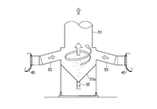
- the second duct 49 includes a second vertical extension 51, a second vertical extension 51, and a second extension arranged to extend upward in the center of the space surrounded by the annular cooling bath 3.
- a plurality of lateral conduits 53 extending in the lateral direction connecting the suction chamber 45 are provided.
- a second funnel-shaped portion 51 a that is inclined downward in the center direction is formed at the lower portion of the second longitudinally extending portion 51, and is formed at the lower end of the second funnel-shaped portion 51 a.
- a second dust discharge mechanism 55 is provided.
- a second ventilation duct 57 is connected to the upper part of the second longitudinally extending portion 51 (see FIGS. 2 and 3).
- the second ventilation duct 57 is connected to a second dust remover 59 and a second suction device.
- a second blower 61 is installed (see FIG. 5).
- the plurality of lateral conduits 53 are radially connected to the second longitudinally extending portion 51 in a state in which each central axis is inclined with respect to the radial direction of the second longitudinally extending portion 51 in plan view ( (See FIG. 9).
- the gas flowing into the second longitudinally extending portion 51 from the plurality of lateral conduits 53 forms a swirling flow in the second longitudinally extending portion 51 ( FIG. 11).
- the dust contained in the suction gas is separated from the gas and falls toward the second dust discharge mechanism 55 as shown in FIG.
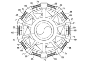
- the first duct 47 includes an annular first annular portion 63 disposed so as to surround the second longitudinally extending portion 51 of the second duct 49, the first annular portion 63, the first suction chamber 43, and the like. And a plurality of first longitudinally extending portions 67 arranged so as to surround the second longitudinally extending portion 51 in a plan view with one end connected to the first annular portion 63. (See FIGS. 3 and 6).
- a plurality of first funnel-shaped portions 69 are attached to the lower surface of the first annular portion 63, and a first dust discharge mechanism 71 is attached to the lower end of the first funnel-shaped portion 69 (FIG. 3). FIG. 13).
- the 1st ventilation duct 73 is connected to the upper part of the 1st vertical direction extension part 67, and the 1st dust removal machine 75, the boiler 77 as a waste heat recovery device, and the 1st suction device are connected to the 1st ventilation duct 73.
- a first blower 79 is installed (see FIG. 5).
- the intake duct 7 is configured as described above, the intake duct 7 can be accommodated inside the ring of the annular cooling tank 3, and the entire apparatus can be made compact.
- a water-sealed seal structure 81 is provided between the lid member 25 and the upper end portion of the cooling tank 3 and between the inner peripheral surface side wall of the cooling tank 3 and the suction chamber forming wall 39.
- the outside air can be sucked from a portion that contributes to cooling without being sucked from the portion when the outside air is sucked (see FIG. 4).
- the operation of the cooler 1 configured as described above will be described.
- the sintered ore 16 is continuously supplied from the supply chute (not shown) to the charging portion 25a of the cooling tank 3 while rotating the cooling tank 3 at a predetermined rotational speed.
- the sintered ore 16 supplied to the cooling bath 3 is gradually deposited in the cooling bath 3.
- By driving the first blower 79 and the second blower 61 negative pressure is generated in the first duct 47 and the second duct 49, and outside air is sucked into the cooling tank 3 through the outer louver part of the cooling tank 3.
- the sintered ore 16 is cooled.
- the longitudinal cross-sectional shape of the cooling region of the cooling bath 3 is made vertically long, and the length of the cooling region of the cooling bath 3 in the height direction is 1/2 or more of the height of the cooling bath 3. Therefore, the gas passage resistance of the cooling tank is reduced, and the load on the blower can be suppressed. Moreover, since the contact area of the sintered ore which contacts low temperature external air can be enlarged, the cooling efficiency of the sintered ore 16 can be improved.
- the gas that has cooled the sintered ore 16 is sucked into the first suction chamber 43 and the second suction chamber 45.
- the gas sucked into the first suction chamber 43 passes through the communication pipe portion 65 of the first duct 47, the first annular portion 63, the first longitudinally extending portion 67, and the first ventilation duct 73, and then the first dust remover. It flows to 75 and is dedusted, and exhaust heat is recovered by the boiler 77.
- the first annular part 63 and the dust are collected by the first dust discharge mechanism 71 via the first funnel part 69.
- the gas sucked into the second suction chamber 45 flows into the second dust remover 59 through the lateral conduit 53, the second longitudinal extension 51, and the second ventilation duct 57, and is removed from the dust. After being cooled to a predetermined temperature in the facility, it is released to the atmosphere.
- the suction chamber is divided into the first suction chamber 43 and the second suction chamber 45 below the first suction chamber 43, and the intake duct is connected to the first suction chamber 43.
- the first duct 47 and a second duct 49 connected to the second suction chamber 45 are provided.
- the suction device is connected to the first suction device connected to the first duct 47 and the second duct 49.
- the gas introduced from the lateral conduit 53 into the second longitudinally extending portion 51 becomes a swirling flow, dust in the gas is separated by the cyclone effect, and the second funnel portion is used to separate the gas. It is collected by the dust discharge mechanism 55. Since the amount of dust contained in the gas sucked through the second suction chamber 45 is less than the amount contained in the gas sucked through the first suction chamber 43, the second dust remover 59 can be simplified and inexpensive. Can be.
- the cooled sintered ore 16 is continuously scraped by the scraper 29 provided at the lower part of the cooling tank 3 as the cooling tank 3 rotates, and is conveyed by the conveyor 83 (FIGS. 2, 3, and 4). (See FIG. 10). As the sinter 16 in the lower layer is scraped, the upper sinter 16 gradually moves to the lower layer. That is, the sintered ore 16 charged from the charging part 25 a at the upper part of the cooling tank 3 is gradually cooled while moving to the lower layer in the cooling tank 3, and is scraped out of the cooling tank 3 by the scraper 29.
- the length in the height direction of the cooling area of the cooling tank 3 is set to be 1/2 or more of the height of the cooling tank 3, and the thickness of the cooling area is set.
- the contact area of the sintered ore that comes into contact with the low temperature outside air can be increased, so the cooling efficiency of the sintered ore is increased. A lot of processing is possible.
- it since it is configured to suck from the suction chamber that covers the entire gas passage part, it is possible to efficiently introduce a large amount of high-temperature gas that has passed through the cooling region in the cooling tank in the thickness direction into the exhaust heat recovery device, and thermal efficiency Can be raised and dust collection is facilitated.
- the longitudinal cross-sectional shape of a cooling tank is vertically long, the gas passage resistance of a cooling tank becomes small and it can also suppress the load of a blower.
- FIG. 14 is a longitudinal sectional view of a sintered ore cooler 91 according to the second embodiment of the present invention.
- the same reference numerals are used for the same parts as in FIGS. 1 to 4 showing the cooler 1 according to the first embodiment. It is attached.
- a cooler 91 shown in FIG. 14 includes a charging unit 25a (see FIG. 7) for charging sintered ore, and a discharge unit for discharging the cooled sintered ore provided below the charging unit 25a. 27, and has an annular cooling tank 3 in plan view. While rotating the cooling tank 3, the sintered ore is charged from the charging unit 25a and blown to the sintered ore in the cooling tank 3.
- the sintered ore is cooled, and the cooled sintered ore is discharged from the discharge unit 27.
- the sintered ore is fired on one side surface of the cooling tank 3, in this embodiment, on the inner peripheral side surface.
- the suction chamber 93 communicates with the suction chamber 93, which has an inner louver portion 21 as a gas passage portion through which gas is allowed to pass while retaining the ore, and forms the suction chamber 93 by covering the entire gas passage portion.
- the intake duct 97 connected to the suction chamber 93 and the gas in the cooling tank 3 are A blower 99 (see FIG.
- a dust passage restricting member 101 having a baffle plate 101a that restricts the passage of dust by changing a part of the flow direction, and a dust collecting portion 103 that collects dust whose passage is restricted by the dust passage restricting member 101. I have.
- the cooling tank 3 has a length in the height direction of the cooling area of the cooling tank 3 that is 1/2 or more of the height of the cooling tank 3, and the thickness of the cooling area of the cooling tank 3. Is set to approximately 1/5 of the height of the cooling tank 3.
- the suction chamber 93 is provided with a dust passage regulating member 101 so as to form a boundary between the space on the gas passage side and the space on the duct side.
- the dust passage restriction member 101 preferably restricts passage of about 50% or more of dust contained in the passing airflow.
- the dust passage restricting member 101 is arranged such that a plurality of baffle plates 101a are spaced apart from each other and inclined with respect to the thickness direction of the dust passage restricting member 101, as shown in the enlarged view encircled in FIG. A louver filter is preferable.
- the dust passage restriction member may be arranged such that the baffle plate is orthogonal to the thickness direction of the dust passage restriction member.
- a plurality of baffle plates having striped openings may be arranged so that the openings are staggered in the thickness direction of the dust passage restriction member.
- the suction chamber 93 is formed without being divided into two upper and lower chambers, and an intake duct 97 is provided so as to communicate with the suction chamber 93.
- the intake duct 97 has a longitudinally extending portion 105 disposed so as to extend upward and downward in the center portion of the space surrounded by the annular cooling tank 3, and between the longitudinally extending portion 105 and the suction chamber 93.
- a funnel-shaped portion 105a that is inclined downward in the center direction is formed at the lower portion of the longitudinally extending portion 105, and a third dust discharge mechanism 109 is formed at the lower end of the funnel-shaped portion 105a.
- a ventilation duct 111 is connected to the upper part of the longitudinally extending portion 105 (see FIG. 17), and a boiler 77 as an exhaust heat recovery device and a blower 99 as a suction device are installed in the ventilation duct 111.
- the dust collection part 103 is provided in the lower part of the suction chamber 93, and collects the dust which fell by the passage restriction being carried out by the dust passage restriction member 101.
- a portion of the suction chamber forming wall 95 that forms the suction chamber 93 that delimits a space on the gas passage portion side is inclined downward and is positioned vertically below the dust passage restriction member 101.
- the 4th dust discharge mechanism 103b for discharging the collected dust is provided in the lower end of the dust receiving part 103a.
- movement peculiar to this Embodiment 2 different from Embodiment 1 is mainly demonstrated.
- a negative pressure is generated in the intake duct 97, and outside air is sucked into the cooling tank 3 through the outer louver portion 23 of the cooling tank 3, and the sintered ore 16 is cooled.
- the gas that has cooled the sintered ore 16 is sucked into the suction chamber 93, passes through the dust passage restricting member 101, flows into the inclined conduit 107 and the ventilation duct 111, and is recovered by the boiler 77 as exhaust heat.
- the gas passing through the dust passage restricting member 101 of the second embodiment is restricted from passing about 50% of the dust contained in the gas, and the dust whose passage is restricted falls to the dust receiving portion 103a and is fourth. It is discharged from the dust discharge mechanism 103b.
- the cooler 91 of the second embodiment by providing the dust passage restriction member 101, about 50% or more of the dust contained in the gas can be collected. In this case, as shown in FIG. Thus, the 1st dust remover 75 required in Embodiment 1 becomes unnecessary.
- FIG. 18 is a longitudinal sectional view of the cooler 113 for the sintered ore 16 according to the third embodiment of the present invention, and shows the cooler 1 according to the first embodiment shown in FIGS. 1 to 4 and the second embodiment.
- the same parts as those in FIGS. 14 and 15 showing 91 are denoted by the same reference numerals.
- the cooler 113 shown in FIG. 18 includes a charging unit 25a for charging the sintered ore 16 and a discharge unit 27 for discharging the cooled sintered ore 16 provided below the charging unit 25a.
- a cooling tank 3 having an annular shape in plan view, and while the cooling tank 3 is rotated, the sintered ore 16 is charged from the charging unit 25a and blown to the sintered ore 16 in the cooling tank 3 for baking. The ore 16 is cooled, and the cooled sintered ore 16 is discharged from the discharge unit 27.
- the inner louver portion 21 is formed on the inner peripheral side surface of the cooling bath 3, and the outer louver portion 23 is formed on the outer peripheral side surface of the cooling bath 3.
- the inner louver portion 21 is a ventilation portion, and an exhaust gas supply chamber 117 that supplies the exhaust gas from the boiler 77 through the circulation duct 115 is provided in a part (approximately two-thirds) on the upper side in the height direction of the ventilation portion.
- the remaining portion (substantially one third) on the lower side in the height direction of the ventilation portion is a portion for ventilating the outside air.
- a suction chamber forming wall 95 that forms a suction chamber 93 by covering the entire outer louver portion 23 (gas passage portion) is provided on the outer peripheral side of the cooling tank 3.
- An intake duct 97 is connected to the suction chamber 93 so as to communicate with the suction chamber 93
- a ventilation duct 111 is connected to the downstream side of the intake duct 97
- a boiler 77 is provided at the downstream end of the ventilation duct 111.
- the exhaust heat recovered by the boiler 77 is supplied to the exhaust gas supply chamber 117 through a circulation duct 115 having one end connected to the boiler 77 and the other end connected to the exhaust gas supply chamber 117, and the inner louver part 21 (ventilation part). Is supplied to the cooling tank 3 via
- the ventilation duct 111 and the circulation duct 115 are connected via a connection duct 119, and a blower 99 is provided closer to the exhaust gas supply chamber 117 than the connection duct 119 in the circulation duct 115. .
- the blower 99 By driving the blower 99, the intake air from the suction chamber 93 by the intake duct 97 and the exhaust heat recovered gas by the circulation duct 115 can be supplied to the exhaust gas supply chamber 117.
- the exhaust gas supply chamber 117 that supplies the exhausted heat recovered gas to the cooling tank 3 is located above the ventilation part.
- the exhaust gas supply chamber 117 is temporarily covered so as to cover the entire ventilation part or cover the lower side. If so, cooling of the sintered ore 16 in the lower part of the cooling tank 3 becomes insufficient, and the sintered ore 16 may be discharged from the discharge part 27 at a high temperature exceeding the allowable range as a product. is there. What is necessary is just to set suitably the range which provides the exhaust gas supply chamber 117 with respect to a ventilation
- the cooling tank 3 has a length in the height direction of the cooling area of the cooling tank 3 that is 1/2 or more of the height of the cooling tank 3 and the thickness of the cooling area of the cooling tank 3. Is set to approximately 1/5 of the height of the cooling tank 3.
- the operation unique to the third embodiment different from the first embodiment will be mainly described.
- a negative pressure is generated in the intake duct 97, and the circulating gas and the outside air are sucked into the cooling tank 3 from the inner louver portion 21 of the cooling tank 3, and the sintered ore 16 is cooled.
- the gas that has cooled the sintered ore 16 is sucked into the suction chamber 93, flows into the ventilation duct 111, and is exhausted and recovered by the boiler 77.
- the exhaust heat recovered gas is supplied to the exhaust gas supply chamber 117 through the circulation duct 115 and is supplied to the cooling tank 3 through the ventilation portion.
- the gas supplied to the cooling bath 3 is used for cooling the sintered ore 16, and then sucked into the suction chamber 93, flows into the ventilation duct 111, and is again recovered by the boiler 77.
- a part of the exhaust heat recovered gas is supplied to the exhaust gas supply chamber 117 through the circulation duct 115 to cool the sintered ore 16.
- the residual heat of the exhaust gas recovered can be used effectively.
- the opening / closing valve 121 is opened and the opening / closing valves 125, 126 are closed, and the boiler 77 is bypassed by the connecting duct 119.
- the on-off valve 127 is closed and the on-off valves 130 and 131 are opened to stop the gas circulation. Therefore, when the boiler 77 is bypassed in this way, the cooling gas (air) supplied to the cooling tank 3 is the outside air taken in through the opening / closing valve 131, and the exhaust gas that has become hot through the cooling tank 3 is cooled by the cooler 120. And is discharged to the outside through the opening / closing valve 130.
- the suction chamber is provided on the outer peripheral side and the circulating gas is returned from the inner peripheral side of the cooling tank as an example.
- the suction chamber When circulating, it is good also as a structure which provides a suction chamber in an inner peripheral side and returns circulating gas from the outer peripheral side of a cooling tank.
- Cooler (Embodiment 1) DESCRIPTION OF SYMBOLS 3 Cooling tank 5 Suction chamber 7 Intake duct 9 Support wheel 11 Rotary table 11a Rail 13 Inner side wall 15 Outer side wall 16 Sintered ore 17 First guide wheel 18 Base 19 Second guide wheel 21 Inner louver part 23 Outer louver Part 25 Lid member 25a Input part 27 Discharge part 29 Scraper 31 Foundation 33 Frame part 35 First guide rail 37 Second guide rail 39 Suction chamber forming wall 41 Intermediate air seal 43 First suction chamber 45 Second suction chamber 47 First duct 49 2nd duct 51 2nd vertical direction extension part 51a 2nd funnel-shaped part 53 Horizontal direction conduit
Landscapes
- Engineering & Computer Science (AREA)
- Mechanical Engineering (AREA)
- Chemical & Material Sciences (AREA)
- Environmental & Geological Engineering (AREA)
- General Engineering & Computer Science (AREA)
- Life Sciences & Earth Sciences (AREA)
- General Life Sciences & Earth Sciences (AREA)
- Geochemistry & Mineralogy (AREA)
- Geology (AREA)
- Manufacturing & Machinery (AREA)
- Materials Engineering (AREA)
- Metallurgy (AREA)
- Organic Chemistry (AREA)
- Chemical Kinetics & Catalysis (AREA)
- Manufacture And Refinement Of Metals (AREA)
- Waste-Gas Treatment And Other Accessory Devices For Furnaces (AREA)
Abstract
Description
特許文献1、2に開示されたものは、いずれも平面視において円環状の冷却槽を回転させると共に冷却槽の上部から焼結鉱を投入し、冷却槽内に冷却ガスとしての空気を通して冷却槽内の焼結鉱を冷却し、冷却後の焼結鉱を冷却槽の下部から排出することを連続的に行うようにしている。
前記冷却槽の一方の側面に焼結鉱を留めるとともにガスを通過させるガス通過部が設けられ、
前記冷却槽の他方の側面のうち、前記ガス通過部と相対する部分が、焼結鉱を留めるとともに空気を通過させる通気部であり、
前記ガス通過部と前記通気部とに挟まれた領域で規定される冷却領域の高さ方向の長さが、前記冷却槽の高さの1/2以上であり、
前記冷却領域は、厚みが前記冷却槽の高さの1/6~1/4の範囲内にあり、
前記冷却槽の内周側及び外周側の双方の側壁の上端が、前記冷却領域の上端よりも前記冷却領域の厚さの1.2倍以上高い位置にあり、
前記ガス通過部の全体を覆うことによって吸引室を形成する吸引室形成壁と、
前記吸引室と連通するように前記吸引室に接続された吸気ダクトと、
前記冷却槽内のガスを吸引するための負圧を前記吸気ダクト内に生じさせるように構成された吸引装置と、
前記吸気ダクトに接続された排熱回収器と、を備えることを特徴とするものである。
前記排熱回収器から排出されたガスの少なくとも一部が前記冷却槽の前記通気部に導かれて循環するよう構成されていることを特徴とするものである。
前記吸気ダクトは、
前記第1吸引室に接続された第1ダクトと、
前記第2吸引室に接続された第2ダクトと、を備え、
前記吸引装置は、前記第1ダクトを通してガスを吸引する第1吸引装置と、前記第2ダクトを通してガスを吸引する第2吸引装置とを含み、
前記第1ダクトのみが前記排熱回収器に接続されていることを特徴とするものである。
前記第1ダクトが、前記冷却槽の上端よりも上方に延びる第1縦方向延出部を含み、
前記第2ダクトが、前記冷却槽の上端よりも上方に延びる第2縦方向延出部を含み、
前記第2縦方向延出部が、前記円環状の冷却槽に囲まれた空間の中心部において上方に延びるように配置され、
前記第1縦方向延出部が、前記円環状の冷却槽に囲まれた空間において、平面視で前記第2縦方向延出部を囲むように複数配置されていることを特徴とするものである。
本実施の形態にかかる焼結鉱の冷却機1は、図1~4に示されるように、平面視にて円環状をなす冷却槽3と、冷却槽3の内周側の側面に形成された吸引室5と、吸引室5に連通するように接続された吸気ダクト7と、吸気ダクト7内に負圧を生じさせる吸引装置(第1ブロワ79、第2ブロワ61)(図5参照)とを備えている。尚、以下に示す本実施形態を含む各実施形態を示す図面においては、寸法比率が厳密に正しくは示されていない箇所も存在する。
以下、各構成を詳細に説明する。
冷却槽3は、下面にレール11aを有し後述する支持ホイール9上を回転する円環状の回転テーブル11と、回転テーブル11の上に立設された内周側側壁13と、内周側側壁13に対して所定の距離を離して立設された外周側側壁15とを有し、これら回転テーブル11、内周側側壁13及び外周側側壁15によって囲まれる空間に焼結鉱16を収容できるようになっている。
冷却槽3の一方の側面、本実施形態1では内周側側壁13に焼結鉱を留めるとともにガスを通過させる内側ルーバ部21が設けられ、冷却槽3の他方の側面、本実施形態1では外周側側壁15のうち、内側ルーバ部21と相対する部分が、焼結鉱を留めるとともに空気を通過させる外側ルーバ部23である。
内側ルーバ部21と外側ルーバ部23とに挟まれた領域で規定される冷却領域の高さ方向の長さが、冷却槽3の高さの1/2以上に設定されている。
冷却槽3の冷却領域は、厚みが高さの略1/5に設定され、図1~図3に示すように、その縦断面形状は縦長になっている。なお、冷却槽3の冷却領域は、圧力損失を小さくして吸引抵抗を減らすためには、厚みが冷却槽3の高さの1/4以下に設定されていればよいが、1/5以下に設定されるのがより好ましい。また、十分な熱回収を可能とするためには、焼結鉱を通した空気を十分に熱することができる必要があり、冷却領域の厚みはある程度大きくしておく必要があるため、冷却槽3の高さに対する厚みの比の下限は1/6程度である。冷却槽3の高さHは、図2~図4に示すように、冷却槽3の床面(回転テーブル11の上面)から内周側側壁13及び外周側側壁15の上端までの距離である。冷却槽の冷却領域の厚みは、好ましくは700mm~2000mm程度であり、更に好ましくは1500~1700mmの範囲内である。
なお、本発明において冷却槽3の冷却領域の厚みとは、高さ方向の中央における、径方向に対向する内壁間の距離である。後述するように、本実施形態では、冷却槽3の内周側側壁13のうちの一部が内側ルーバ部21となっているが、このようなルーバ構造である場合には、内壁間の距離とは、ルーバ部の冷却槽内方の端部間の距離、すなわち対向するルーバ部の間の最短距離である。
回転テーブル11の内周面には第1ガイドホイール17が設けられており、また内周側側壁13の内周面上部には第2ガイドホイール19が設けられており、後述する第1ガイドレール35及び第2ガイドレール37に沿って転動できるようになっている。
このように焼結鉱16の設計上の充填高さを設定する理由は、ガス通過部よりも上方に焼結鉱16が所定量以上存在するようにすることで、ブロワによって大気を吸気する際に、冷却槽3の上端側から充填された焼結鉱16の上面を介して大気が吸気されるのを防止するためである。これにより、吸引される空気が全て外側ルーバ部(通気部)23から冷却領域を通して吸引されることとなり、焼結鉱16の上面から十分に熱されていない空気が吸引室側に取り込まれることが防止され、熱回収効率を高めることができる。
尚、内周側側壁13及び外周側側壁15はできる限り低くすることが望ましい。従って、これらの上端は、通常、上記のような制約により定まる設計上の充填高さまで充填された焼結鉱16の上端近傍となるように設定される。従って、上記説明において、冷却槽3の床面から内周側側壁13及び外周側側壁15の上端までの距離としている本発明における冷却槽3の高さHは、焼結鉱16の設計上の充填高さに近い。従って、本発明においては、冷却槽3の冷却領域の厚みが、焼結鉱16の設計上の充填高さの1/6~1/4、好ましくは1/6~1/5の範囲内に設定されていると言うこともできる。
冷却槽3の円環の内側には、基礎31が設けられ、さらにその上に架構部33が構築されている。架構部33は、前述した蓋部材25を支持している。また、架構部33は、後述する吸引室5を形成する吸引室形成壁39や吸気ダクト7を支持している。
架構部33の基礎31外周面には第1ガイドレール35が、また架構部33の上部の外周面には第2ガイドレール37がそれぞれ設けられており(図4参照)、冷却槽3に設けた第1ガイドホイール17及び第2ガイドホイール19が走行できるようになっている。
このように、第1ガイドホイール17及び第2ガイドホイール19を設けることで、回転テーブル11は、安定して回転できるようになっている。なお、回転テーブル11は、図示しない駆動手段によって所定の回転数で回転する。
冷却槽3の内周側側壁13における内側ルーバ部21の全体を覆うようにフード状の吸引室形成壁39が設けられ、この吸引室形成壁39が吸引室5を形成している。吸引室5は、平面視で円環状になっており、架構部33に取り付けられている。
吸引室5における高さ方向の中間よりも少し下の部分には、吸引室5を上下に分割する中間エアーシール41が設けられており、吸引室5は、第1吸引室43と、第1吸引室43よりも下方の第2吸引室45の2つに分割されている。
吸気ダクト7は、吸引室5と連通するように吸引室形成壁39に接続されている。
本実施の形態の吸気ダクト7は、第1吸引室43に接続された第1ダクト47と、第2吸引室45に接続された第2ダクト49とを備えている。本願発明における吸気ダクトは、冷却槽の内周側側面の大部分からガスを吸引するために、吸引室全体と連通するように接続されている。そのため、吸引室全体が単一の空間を形成するように構成されている場合には吸気ダクトは単にこの吸引室に接続されていればよく、1系統のダクトで足りる。本実施形態のように吸引室が2つに分割された形態においては、吸気ダクトが吸引室全体と連通するために、それぞれの分室(第1吸引室43と第2吸引室45)に接続された第1ダクトと第2ダクトとの2系統の吸気ダクトを備える必要がある。
第2ダクト49は、円環状の冷却槽3に囲まれた空間の中心部において上方に延びるように配置された第2縦方向延出部51と、第2縦方向延出部51と第2吸引室45との間を接続する横方向に延びる複数の横方向導管53を備えている。
第2縦方向延出部51の下部には、図3に示すように、下方に向かって中心方向に傾斜する第2漏斗状部51aが形成されており、第2漏斗状部51aの下端に第2ダスト排出機構55が設けられている。
第2縦方向延出部51の上部には、第2通風ダクト57が接続され(図2、図3参照)、第2通風ダクト57には第2除塵機59と、第2吸引装置としての第2ブロワ61が設置されている(図5参照)。
第1ダクト47は、第2ダクト49の第2縦方向延出部51を囲むように配置された円環状の第1円環部63と、第1円環部63と第1吸引室43とを連通させる連通管部65と、一端が第1円環部63に接続されて平面視で第2縦方向延出部51を囲むように配置された複数の第1縦方向延出部67によって構成されている(図3、図6参照)。
第1円環部63の下面には、複数の第1漏斗状部69が取り付けられており、第1漏斗状部69の下端部には第1ダスト排出機構71が取り付けられている(図3、図13参照)。
第1縦方向延出部67の上部には、第1通風ダクト73が接続され、第1通風ダクト73には第1除塵機75、排熱回収器としてのボイラ77、第1吸引装置としての第1ブロワ79が設置されている(図5参照)。
上述のように、冷却槽3は回転するが、蓋部材25と吸引室形成壁39は架構部33に固定されており、回転しない。そのため、冷却槽3とこれら蓋部材25及び吸引室形成壁39の接続部において、両者が相対移動できる状態にする必要がある。その一方で、上記の接続部に通風可能な隙間があると、冷却槽3に外気を取り込む際に、外側ルーバ部23以外から外気が入り込むことになり、焼結鉱16の冷却に寄与する外気取り込み量が減るために冷却効率が低下する。
そこで、本実施の形態では、蓋部材25と冷却槽3の上端部との間、冷却槽3の内周面側側壁と吸引室形成壁39との間に水封式のシール構造81を設け、外気を吸引する際に当該部位から吸引されることなく、冷却に寄与する箇所から外気を吸引できるようにして、冷却効率を向上させている(図4参照)。
冷却槽3を所定の回転数で回転させながら、図示しない供給シュートから焼結鉱16を冷却槽3の投入部25aに連続して供給する。冷却槽3に供給された焼結鉱16は、冷却槽3内に徐々に堆積される。
第1ブロワ79、第2ブロワ61を駆動することで、第1ダクト47及び第2ダクト49内に負圧が生じ、冷却槽3の外側ルーバ部を介して外気が冷却槽3内に吸引されて、焼結鉱16の冷却が行われる。このとき、前述したように、冷却槽3の冷却領域の縦断面形状を縦長にすると共に、冷却槽3の冷却領域の高さ方向の長さが、冷却槽3の高さの1/2以上となっているので、冷却槽のガス通過抵抗が小さくなり、ブロワの負荷を抑えることができる。また、低温の外気に触れる焼結鉱の接触面積を大きくすることができるため、焼結鉱16の冷却効率向上が可能となる。
また、第2吸引室45に吸引されたガスは、横方向導管53、第2縦方向延出部51、第2通風ダクト57を介して第2除塵機59に流れて除塵され、図示しない冷却設備にて所定の温度に冷却された後、大気に放出される。
第2吸引室45を介して吸引されるガスに含まれる塵埃は第1吸引室43を介して吸引されるガスに含まれる量よりも少ないので、第2除塵機59を簡易的な低廉なものにすることができる。
図14は本発明の実施の形態2に係る焼結鉱の冷却機91の縦断面図であり、実施の形態1の冷却機1を示した図1~4と同一部分には同一の符号を付してある。
図14に示す冷却機91は、焼結鉱を投入するための投入部25a(図7参照)と、投入部25aよりも下方に設けられ、冷却された焼結鉱を排出するための排出部27とを有し、平面視にて円環状をなす冷却槽3を備え、冷却槽3を回転させながら焼結鉱を投入部25aから投入すると共に冷却槽3内の焼結鉱に送風して焼結鉱を冷却し、冷却された焼結鉱を排出部27から排出するように構成されたものであって、冷却槽3の一方の側面、本実施形態では内周側の側面に、焼結鉱を留めるとともにガスを通過させるガス通過部としての内側ルーバ部21を有し、ガス通過部の全体を覆うことによって吸引室93を形成する吸引室形成壁95と、吸引室93と連通するように吸引室93に接続された吸気ダクト97と、冷却槽3内のガスを吸引するための負圧を前記吸気ダクト97内に生じさせるように構成された吸引装置としてのブロワ99(図17参照)と、吸引室93内におけるガス通過部側からダクト側への気流の少なくとも一部の流れ方向を変化させてダストの通過を規制する邪魔板101aを有するダスト通過規制部材101と、ダスト通過規制部材101によって通過が規制されたダストを捕集するダスト捕集部103とを備えている。
吸引室93には、ガス通過部側の空間と前記ダクト側の空間との間に境界を形成するようにダスト通過規制部材101が設けられている。ダスト通過規制部材101は、通過する気流に含まれるダストの約50%以上の通過を規制するものが好ましい。
ダスト通過規制部材101は、図15の丸で囲んだ拡大図に示すように、複数の邪魔板101aが、互いに離間し且つダスト通過規制部材101の厚さ方向に対して傾斜するように配置されたルーバーフィルタであることが好ましい。
もっとも、ダスト通過規制部材は、邪魔板がダスト通過規制部材の厚み方向に直交するように配置されたものであってもよい。この場合、縞状の開口を有する複数の邪魔板を、前記開口がダスト通過規制部材の厚み方向で千鳥配置されるよう重ねるようにして配置してもよい。
吸気ダクト97は、円環状の冷却槽3に囲まれた空間の中心部において上下方に延びるように配置された縦方向延出部105と、縦方向延出部105と吸引室93との間を接続する斜めに延びる複数の傾斜導管107を備えている。傾斜導管107は、図16に示すように、縦方向延出部105から放射状に設けられている。
縦方向延出部105の下部には、図14に示すように、下方に向かって中心方向に傾斜する漏斗状部105aが形成されており、漏斗状部105aの下端に第3ダスト排出機構109が設けられている。
縦方向延出部105の上部には、通風ダクト111が接続され(図17参照)、通風ダクト111には排熱回収器としてのボイラ77、吸引装置としてのブロワ99が設置されている。
ダスト捕集部103は、吸引室93を形成する吸引室形成壁95のうち、ガス通過部側の空間を画定する部分が、下方に向かって傾斜するとともにダスト通過規制部材101の垂直下方に位置するダスト受け部103aを有している。そして、ダスト受け部103aの下端には、捕集したダストを排出するための第4ダスト排出機構103bが設けられている。
ブロワ99を駆動することで、吸気ダクト97内に負圧が生じ、冷却槽3の外側ルーバ部23を介して外気が冷却槽3内に吸引されて、焼結鉱16の冷却が行われる。
焼結鉱16を冷却したガスは、吸引室93に吸引され、ダスト通過規制部材101を通過して傾斜導管107、通風ダクト111に流れてボイラ77によって排熱回収される。
本実施の形態2のダスト通過規制部材101を通過するガスは、ガスに含まれる約50%のダストの通過が規制され、通過が規制されたダストはダスト受け部103aに落下して、第4ダスト排出機構103bから排出される。
図18は本発明の実施の形態3に係る焼結鉱16の冷却機113の縦断面図であり、実施の形態1の冷却機1を示した図1~4、実施の形態2の冷却機91を示した図14、図15と同一部分には同一の符号を付してある。
図18に示す冷却機113は、焼結鉱16を投入するための投入部25aと、投入部25aよりも下方に設けられ、冷却された焼結鉱16を排出するための排出部27とを有し、平面視にて円環状をなす冷却槽3を備え、冷却槽3を回転させながら焼結鉱16を投入部25aから投入すると共に冷却槽3内の焼結鉱16に送風して焼結鉱16を冷却し、冷却された焼結鉱16を排出部27から排出するように構成されたものである。
ボイラ77によって排熱回収されたガスは、一端側がボイラ77に連結され、他端側が排ガス供給室117に連結された循環ダクト115を通して排ガス供給室117に供給され、内側ルーバ部21(通気部)を介して冷却槽3に供給されるようになっている。
なお、排熱回収されたガスを冷却槽3に供給する排ガス供給室117を、通気部の上側にしたのは、仮に排ガス供給室117を通気部の全体を覆うようにしたり、下側を覆うようにしたりすると、冷却槽3の下部における焼結鉱16の冷却が不十分となり、焼結鉱16が製品としての許容範囲を超えた高温で排出部27から排出される可能性があるからである。
通気部に対して排ガス供給室117を設ける範囲は、冷却槽3の容量、排熱回収されたガスの温度等によって、適宜設定すればよい。
ブロワ99を駆動することで、吸気ダクト97内に負圧が生じ、冷却槽3の内側ルーバ部21から循環ガス及び外気が冷却槽3内に吸引されて、焼結鉱16の冷却が行われる。
焼結鉱16を冷却したガスは、吸引室93に吸引され、通風ダクト111に流れてボイラ77によって排熱回収される。
3 冷却槽
5 吸引室
7 吸気ダクト
9 支持ホイール
11 回転テーブル
11a レール
13 内周側側壁
15 外周側側壁
16 焼結鉱
17 第1ガイドホイール
18 基台
19 第2ガイドホイール
21 内側ルーバ部
23 外側ルーバ部
25 蓋部材
25a 投入部
27 排出部
29 スクレーパ
31 基礎
33 架構部
35 第1ガイドレール
37 第2ガイドレール
39 吸引室形成壁
41 中間エアーシール
43 第1吸引室
45 第2吸引室
47 第1ダクト
49 第2ダクト
51 第2縦方向延出部
51a 第2漏斗状部
53 横方向導管
55 第2ダスト排出機構
57 第2通風ダクト
59 第2除塵機
61 第2ブロワ
63 第1円環部
65 連通管部
67 第1縦方向延出部
69 第1漏斗状部
71 第1ダスト排出機構
73 第1通風ダクト
75 第1除塵機
77 ボイラ
79 第1ブロワ
81 シール構造
83 コンベア
91 冷却機(実施の形態2)
93 吸引室
95 吸引室形成壁
97 吸気ダクト
99 ブロワ
101 ダスト通過規制部材
101a 邪魔板
103 ダスト捕集部
103a ダスト受け部
103b 第4ダスト排出機構
105 縦方向延出部
105a 漏斗状部
107 傾斜導管
109 第3ダスト排出機構
111 通風ダクト
113 冷却機(実施の形態3)
115 循環ダクト
117 排ガス供給室
119 連結ダクト
120 冷却器
121、125、126、127、130、131 開閉バルブ
Claims (11)
- 焼結鉱を投入するための投入部と、該投入部よりも下方に設けられ、冷却された焼結鉱を排出するための排出部とを有し、平面視にて円環状をなす冷却槽を備え、該冷却槽を回転させながら焼結鉱を前記投入部から投入すると共に前記冷却槽内の焼結鉱に送風して該焼結鉱を冷却し、冷却された焼結鉱を前記排出部から排出するように構成された、焼結鉱を冷却する冷却機であって、
前記冷却槽の一方の側面に焼結鉱を留めるとともにガスを通過させるガス通過部が設けられ、
前記冷却槽の他方の側面のうち、前記ガス通過部と相対する部分が、焼結鉱を留めるとともに空気を通過させる通気部であり、
前記ガス通過部と前記通気部とに挟まれた領域で規定される冷却領域の高さ方向の長さが、前記冷却槽の高さの1/2以上であり、
前記冷却領域は、厚みが前記冷却槽の高さの1/6~1/4の範囲内にあり、
前記冷却槽の内周側及び外周側の双方の側壁の上端が、前記冷却領域の上端よりも前記冷却領域の厚さの1.2倍以上高い位置にあり、
前記ガス通過部の全体を覆うことによって吸引室を形成する吸引室形成壁と、
前記吸引室と連通するように前記吸引室に接続された吸気ダクトと、
前記冷却槽内のガスを吸引するための負圧を前記吸気ダクト内に生じさせるように構成された吸引装置と、
前記吸気ダクトに接続された排熱回収器と、
を備えることを特徴とする焼結鉱の冷却機。 - 前記冷却槽の冷却領域は、厚みが高さの1/6~1/5の範囲内にあることを特徴とする請求項1に記載の焼結鉱の冷却機。
- 前記冷却槽は、内周側及び外周側の双方の側壁の上端が、前記ガス通過部の上端よりも前記冷却槽の厚さの1.5倍以上高い位置にあることを特徴とする請求項1または2に記載の焼結鉱の冷却機。
- 前記排熱回収器と前記冷却槽の前記通気部との間を接続する循環ダクトをさらに備え、
前記排熱回収器から排出されたガスの少なくとも一部が前記冷却槽の前記通気部に導かれて循環するよう構成されていることを特徴とする請求項1~3のいずれか1項に記載の焼結鉱の冷却機。 - 前記吸引室が、第1吸引室と、前記第1吸引室よりも下方の第2吸引室との2つに分割されており、
前記吸気ダクトは、
前記第1吸引室に接続された第1ダクトと、
前記第2吸引室に接続された第2ダクトと、を備え、
前記吸引装置は、前記第1ダクトを通してガスを吸引する第1吸引装置と、前記第2ダクトを通してガスを吸引する第2吸引装置とを含み、
前記第1ダクトのみが前記排熱回収器に接続されていることを特徴とする請求項1~4のいずれか1項に記載の焼結鉱の冷却機。 - 前記ガス通過部が前記冷却槽の内周側の側面に設けられており、
前記第1ダクトが、前記冷却槽の上端よりも上方に延びる第1縦方向延出部を含み、
前記第2ダクトが、前記冷却槽の上端よりも上方に延びる第2縦方向延出部を含み、
前記第2縦方向延出部が、前記円環状の冷却槽に囲まれた空間の中心部において上方に延びるように配置され、
前記第1縦方向延出部が、前記円環状の冷却槽に囲まれた空間において、平面視で前記第2縦方向延出部を囲むように複数配置されていることを特徴とする請求項5に記載の焼結鉱の冷却機。 - 前記第2ダクトが、前記第2縦方向延出部と前記第2吸引室との間を接続する横方向に延びる複数の横方向導管を備え、該複数の横方向導管は、該複数の横方向導管から前記第2縦方向延出部内に流入したガスが該第2縦方向延出部内で旋回流を形成するように、平面視において各々の中心軸が前記第2縦方向延出部の径方向に対して傾いた状態で前記第2縦方向延出部に接続されていることを特徴とする、請求項6に記載の焼結鉱の冷却機。
- 前記吸引室内におけるガス通過部側からダクト側への気流の少なくとも一部の流れ方向を変化させてダストの通過を規制する邪魔板を有するダスト通過規制部材と、該ダスト通過規制部材によって通過が規制されたダストを捕集するダスト捕集部とを、更に備えたことを特徴とする請求項1~7のいずれか1項に記載の焼結鉱の冷却機。
- 前記ダスト通過規制部材は、複数の前記邪魔板が、互いに離間し且つ前記ダスト通過規制部材の厚さ方向に対して傾斜するように配置されたルーバーフィルタであることを特徴とする請求項8に記載の焼結鉱の冷却機。
- 前記ダスト通過規制部材は、前記吸引室内において、前記ガス通過部側の空間と前記ダクト側の空間との間に境界を形成するように設けられていることを特徴とする請求項8又は請求項9に記載の焼結鉱の冷却機。
- 前記ダスト捕集部は、吸引室を形成する吸引室形成壁のうち、前記ガス通過部側の空間を画定する部分が、下方に向かって傾斜するとともに前記ダスト通過規制部材の垂直下方に位置するダスト受け部を有し、ダスト受け部の下端にダスト排出機構が設けられていることを特徴とする請求項8~10のいずれか1項に記載の焼結鉱の冷却機。
Priority Applications (1)
| Application Number | Priority Date | Filing Date | Title |
|---|---|---|---|
| BR112016026804-0A BR112016026804B1 (pt) | 2014-05-21 | 2015-04-15 | resfriador para resfriar minério sinterizado |
Applications Claiming Priority (4)
| Application Number | Priority Date | Filing Date | Title |
|---|---|---|---|
| JP2014105191 | 2014-05-21 | ||
| JP2014-105191 | 2014-05-21 | ||
| JP2014-243624 | 2014-12-02 | ||
| JP2014243624A JP6436748B2 (ja) | 2014-05-21 | 2014-12-02 | 焼結鉱の冷却機 |
Publications (1)
| Publication Number | Publication Date |
|---|---|
| WO2015178132A1 true WO2015178132A1 (ja) | 2015-11-26 |
Family
ID=54553808
Family Applications (1)
| Application Number | Title | Priority Date | Filing Date |
|---|---|---|---|
| PCT/JP2015/061528 WO2015178132A1 (ja) | 2014-05-21 | 2015-04-15 | 焼結鉱の冷却機 |
Country Status (4)
| Country | Link |
|---|---|
| JP (1) | JP6436748B2 (ja) |
| BR (1) | BR112016026804B1 (ja) |
| TW (1) | TWI588431B (ja) |
| WO (1) | WO2015178132A1 (ja) |
Cited By (3)
| Publication number | Priority date | Publication date | Assignee | Title |
|---|---|---|---|---|
| CN109813125A (zh) * | 2019-03-18 | 2019-05-28 | 彭武星 | 一种带均匀透风装置的烧结矿立式冷却窑 |
| CN114945691A (zh) * | 2020-03-31 | 2022-08-26 | 普锐特冶金技术日本有限公司 | 烧结矿的冷却装置 |
| CN116136361A (zh) * | 2023-04-20 | 2023-05-19 | 泽州县金秋铸造有限责任公司 | 一种升降式竖冷窑冷却机构 |
Families Citing this family (4)
| Publication number | Priority date | Publication date | Assignee | Title |
|---|---|---|---|---|
| JP6638665B2 (ja) * | 2017-02-09 | 2020-01-29 | 東芝三菱電機産業システム株式会社 | クーラ設備の風量制御装置 |
| JP6638666B2 (ja) * | 2017-02-09 | 2020-01-29 | 東芝三菱電機産業システム株式会社 | クーラ設備の風量制御装置 |
| CN108955277A (zh) * | 2017-05-23 | 2018-12-07 | 中冶长天国际工程有限责任公司 | 一种利用烧结矿余热加热烧结废气实现低成本脱硝的系统 |
| JP7346558B2 (ja) * | 2019-04-23 | 2023-09-19 | Primetals Technologies Japan株式会社 | 粒状物の冷却装置及びスクレーパ |
Citations (5)
| Publication number | Priority date | Publication date | Assignee | Title |
|---|---|---|---|---|
| JPS5763646A (en) * | 1980-10-06 | 1982-04-17 | Sumitomo Heavy Ind Ltd | Cooler for sintered ore |
| JPS5792758U (ja) * | 1980-11-25 | 1982-06-08 | ||
| JPS61183959U (ja) * | 1985-05-07 | 1986-11-17 | ||
| JPS61187370U (ja) * | 1985-05-15 | 1986-11-21 | ||
| JP2004069135A (ja) * | 2002-08-05 | 2004-03-04 | Nippon Steel Corp | 焼結鉱用クーラーの除塵装置 |
Family Cites Families (3)
| Publication number | Priority date | Publication date | Assignee | Title |
|---|---|---|---|---|
| JPS5521035Y2 (ja) * | 1974-11-18 | 1980-05-20 | ||
| JPS61187370A (ja) * | 1985-02-15 | 1986-08-21 | Toshiba Corp | Mosfetの製造方法 |
| JP5138245B2 (ja) * | 2007-03-20 | 2013-02-06 | 三菱日立製鉄機械株式会社 | 焼結鉱冷却装置 |
-
2014
- 2014-12-02 JP JP2014243624A patent/JP6436748B2/ja active Active
-
2015
- 2015-04-15 WO PCT/JP2015/061528 patent/WO2015178132A1/ja active Application Filing
- 2015-04-15 BR BR112016026804-0A patent/BR112016026804B1/pt active IP Right Grant
- 2015-05-20 TW TW104116025A patent/TWI588431B/zh active
Patent Citations (5)
| Publication number | Priority date | Publication date | Assignee | Title |
|---|---|---|---|---|
| JPS5763646A (en) * | 1980-10-06 | 1982-04-17 | Sumitomo Heavy Ind Ltd | Cooler for sintered ore |
| JPS5792758U (ja) * | 1980-11-25 | 1982-06-08 | ||
| JPS61183959U (ja) * | 1985-05-07 | 1986-11-17 | ||
| JPS61187370U (ja) * | 1985-05-15 | 1986-11-21 | ||
| JP2004069135A (ja) * | 2002-08-05 | 2004-03-04 | Nippon Steel Corp | 焼結鉱用クーラーの除塵装置 |
Cited By (3)
| Publication number | Priority date | Publication date | Assignee | Title |
|---|---|---|---|---|
| CN109813125A (zh) * | 2019-03-18 | 2019-05-28 | 彭武星 | 一种带均匀透风装置的烧结矿立式冷却窑 |
| CN114945691A (zh) * | 2020-03-31 | 2022-08-26 | 普锐特冶金技术日本有限公司 | 烧结矿的冷却装置 |
| CN116136361A (zh) * | 2023-04-20 | 2023-05-19 | 泽州县金秋铸造有限责任公司 | 一种升降式竖冷窑冷却机构 |
Also Published As
| Publication number | Publication date |
|---|---|
| TW201604510A (zh) | 2016-02-01 |
| TWI588431B (zh) | 2017-06-21 |
| JP2016001100A (ja) | 2016-01-07 |
| BR112016026804B1 (pt) | 2021-01-26 |
| JP6436748B2 (ja) | 2018-12-12 |
Similar Documents
| Publication | Publication Date | Title |
|---|---|---|
| JP6436748B2 (ja) | 焼結鉱の冷却機 | |
| KR101999600B1 (ko) | 소결광 냉각기 | |
| JP5138245B2 (ja) | 焼結鉱冷却装置 | |
| CN104714617A (zh) | 用于将净化空气引入到控制箱内部的气道装置 | |
| JP2016001100A5 (ja) | ||
| CN101479029A (zh) | 三相蒸汽分配器 | |
| JP6591559B2 (ja) | 高温バルク材料を冷却するための冷却器のための粉塵排出の低減のための境界部 | |
| RU2555287C2 (ru) | Охлаждающее устройство для горячего насыпного материала | |
| EP3550038B1 (en) | Facility for manufacturing sintered ores | |
| JP6976381B2 (ja) | 光輝焼鈍炉におけるホワイトパウダー除去装置 | |
| KR101527856B1 (ko) | 냉각 보조 유닛 및 이를 구비하는 냉각 장치 | |
| KR20140137446A (ko) | 공압식 쓰레기 이송시스템의 출구 공기 처리 방법 및 장치 | |
| KR102083538B1 (ko) | 소결광 제조 설비 | |
| JP5248136B2 (ja) | コークス乾式消火設備用バケットの粉塵飛散防止装置および粉塵飛散防止方法 | |
| KR102681060B1 (ko) | 유체 정화 장치 및 이를 포함하는 전력 기기 | |
| CN107830558A (zh) | 带有在抽吸孔之前的分配板的抽油烟装置 | |
| KR20130099182A (ko) | 엘리베이터의 냉각장치 | |
| KR101909508B1 (ko) | 소결광 제조 설비 | |
| JP2017075710A (ja) | 焼結鉱冷却装置 | |
| CN106705618A (zh) | 型煤立式烘干机 | |
| KR101586398B1 (ko) | 원료처리장치 | |
| WO2020009137A1 (ja) | コークス乾式消火設備 | |
| US1060389A (en) | Metallurgical furnace. | |
| JP2021063631A (ja) | 焼結鉱冷却装置 | |
| TW201601231A (zh) | 用以與處理晶圓狀物件用之設備一起使用的收集器 |
Legal Events
| Date | Code | Title | Description |
|---|---|---|---|
| 121 | Ep: the epo has been informed by wipo that ep was designated in this application |
Ref document number: 15796007 Country of ref document: EP Kind code of ref document: A1 |
|
| NENP | Non-entry into the national phase |
Ref country code: DE |
|
| REG | Reference to national code |
Ref country code: BR Ref legal event code: B01A Ref document number: 112016026804 Country of ref document: BR |
|
| 122 | Ep: pct application non-entry in european phase |
Ref document number: 15796007 Country of ref document: EP Kind code of ref document: A1 |
|
| ENP | Entry into the national phase |
Ref document number: 112016026804 Country of ref document: BR Kind code of ref document: A2 Effective date: 20161116 |