WO2015177922A1 - 回転電機 - Google Patents
回転電機 Download PDFInfo
- Publication number
- WO2015177922A1 WO2015177922A1 PCT/JP2014/063700 JP2014063700W WO2015177922A1 WO 2015177922 A1 WO2015177922 A1 WO 2015177922A1 JP 2014063700 W JP2014063700 W JP 2014063700W WO 2015177922 A1 WO2015177922 A1 WO 2015177922A1
- Authority
- WO
- WIPO (PCT)
- Prior art keywords
- shaft
- electrical machine
- rotating electrical
- rod
- axial direction
- Prior art date
- Legal status (The legal status is an assumption and is not a legal conclusion. Google has not performed a legal analysis and makes no representation as to the accuracy of the status listed.)
- Ceased
Links
Images






Classifications
-
- H—ELECTRICITY
- H02—GENERATION; CONVERSION OR DISTRIBUTION OF ELECTRIC POWER
- H02K—DYNAMO-ELECTRIC MACHINES
- H02K21/00—Synchronous motors having permanent magnets; Synchronous generators having permanent magnets
- H02K21/02—Details
Definitions
- the disclosed embodiment relates to a rotating electrical machine.
- Patent Document 1 discloses a stator in which a stator winding and a stator core are installed, a rotor in which a plurality of magnetic pole portions in which field magnets are installed are divided into two sets, and a rotor that rotates relatively.
- a rotating electrical machine having a mechanism for relatively rotating a pair of magnetic pole portions is described.
- the rotating mechanism is a screw fitting with a member that supports a magnetic pole portion that rotates with respect to the shaft, and a member that is movable in the axial direction on the outside of the shaft, and a feed screw for moving the member in the axial direction Mechanism.
- the present invention has been made in view of such problems, and an object of the present invention is to provide a variable field type rotating electrical machine capable of reducing the size in the radial direction.
- variable field type rotating electrical machine that changes a field magnetic flux, a shaft, a fixed rotor fixed to the shaft, and the fixed
- a movable rotor connected to the shaft so as to rotate relative to the rotor, and an inner side of the shaft, which slides on the shaft and moves in the axial direction to relatively rotate the movable rotor.
- a rotating electrical machine having a rod to be moved and a drive mechanism that is arranged on one side in the axial direction of the shaft and moves the rod in the axial direction is applied.
- variable field type rotating electrical machine that changes a field magnetic flux, which operates in the axial direction of a shaft, a rotor including a permanent magnet, and the shaft.
- a rotating electrical machine having means for changing the field magnetic flux of the rotor and means for operating the means for changing the field magnetic flux in the axial direction is applied.
- the size in the radial direction of the variable field type rotating electrical machine can be reduced.
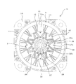
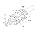
- FIG. 2 is a cross-sectional view taken along the line AA in FIG. It is the side view which looked at the rotary electric machine from the non-load side.
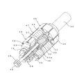
- It is a perspective view showing the structure of a shaft, a slider, and a hub. It is a perspective view showing the structure of the shaft which connected the rod, and a rotor partially fractured
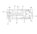
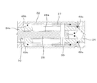
- It is explanatory drawing showing the flow of grease when a rod moves to the load side.
- the rotating electrical machine 1 is a variable field type rotating electrical machine capable of changing a field magnetic flux.
- the rotating electrical machine 1 may be a motor or a generator.
- the rotating electrical machine 1 includes an annular stator 2 provided on the inner peripheral surface of a substantially cylindrical frame 17 and a shaft concentrically disposed on the radially inner side of the stator 2. 34 and the rotor 3 provided on the shaft 34.
- the rotor 3 is divided into a plurality of parts in the axial direction and is configured to be rotatable relative to each other.
- the rotor 3 is divided into three in the axial direction, one movable rotor 47 disposed in the center in the axial direction, and the load side so as to be adjacent to the movable rotor 47 (right side in FIG. 1).
- a fixed rotor 48 disposed on the anti-load side (left side in FIG. 1).
- load side refers to the direction in which the shaft 34 protrudes from the rotating electrical machine 1 (right side in FIG. 1)
- anti-load side refers to the opposite direction of the load side, that is, the rotating electrical machine 1.
- the direction (left side in FIG. 1) in which the drive mechanism 50 is disposed is indicated.
- a load side plate 31 and an anti-load side plate 33 are disposed at both ends of the rotor 3 in the axial direction.
- the load side plate 31 includes a cylindrical portion 31a into which the shaft 34 is inserted, and a flange portion 31b provided on the outer periphery of the cylindrical portion 31a.
- the cylindrical portion 31a is fixed to the shaft 34 by a fixing bolt 61, and the flange portion 31b is fixed to the load-side end surface of the fixed rotor 46 by a bolt (not shown). Thereby, the fixed rotor 46 is fixed to the shaft 34 via the load side plate 31.
- the anti-load side plate 33 has a cylindrical portion 33a into which the shaft 34 is inserted, and a flange portion 33b provided on the outer periphery of the cylindrical portion 33a.
- the cylindrical portion 33a is fixed to the shaft 34 by a fixing bolt (not shown), and the flange portion 33b is fixed to the end surface on the counterload side of the fixed rotor 48 by a bolt (not shown).
- the fixed rotor 48 is fixed to the shaft 34 via the anti-load side plate 33.
- a load side bearing 18 is inserted between the shaft 34 and the load side bracket 16, and an anti load side bearing 19 (second bearing) is provided between the cylindrical portion 33 a of the anti load side plate 33 and the anti load side bracket 15. Is equivalent to one example).
- the shaft 34 and the like are rotatably supported by the load side bracket 16 and the antiload side bracket 15 via the load side bearing 18 and the antiload side bearing 19.
- the anti-load side bearing 19 is composed of a pair of angular bearings arranged so that the axial support directions face each other.
- the pair of anti-load side bearings 19 are attached to the anti-load side bracket 15 by bolts 14.
- the pair of anti-load side bearings 19 are arranged so that the axial support directions face each other, thereby supporting the radial force acting on the shaft 34 and the anti-load side plate 33 in addition to the shaft 34. Further, it is possible to support the axial force acting on the anti-load side plate 33.
- the load side bearing 18 is a radial bearing and supports a radial force acting on the shaft 34.
- the load side bearing 18 is covered with a bearing cover 22.
- the anti-load side bracket 15 and the frame 17 are fixed to the load side bracket 16 by frame fastening bolts 11 inserted from the anti-load side.
- a support portion 20 a of the sensor magnet 20 is attached with a bolt 35 to the end portion on the anti-load side of the cylindrical portion 33 a of the anti-load side plate 33.
- the anti-load side bracket 15 is provided with a position detector 25 that detects the rotational position of the rotor 3 by detecting the magnetism of the sensor magnet 20.
- the rotating electrical machine 1 includes a rod 28 and a drive mechanism 50.
- the rod 28 is disposed on the inner side of the shaft 34 on the non-load side, and slides with the shaft 34 and moves in the axial direction, thereby rotating the movable rotor 47 relative to the fixed rotors 46 and 48.
- the drive mechanism 50 is disposed on the anti-load side (an example of one axial side) of the shaft 34 and moves the rod 28 in the axial direction.
- the stator 2 is wound around the annular stator core 13 provided on the inner peripheral surface of the frame 17 and having a plurality (12 in this example) of teeth portions 13 a and the plurality of teeth portions 13 a. And a plurality of stator windings 12 (in this example, 12). On the side opposite to the load side of the stator core 13, a connection portion 21 for connecting the terminals at the start and end of winding of the stator winding 12 is arranged.
- the movable rotor 47 includes a rotor core 38 disposed with a magnetic gap between the stator 2 and a plurality (16 in this example) of permanent magnets provided on the rotor core 38. 39.
- the plurality of permanent magnets 39 is an aspect in which two permanent magnets 39, 39 in which N poles or S poles of the same polarity are opposed to each other as seen from the axial direction form a V-shaped pair projecting radially inward.
- the opposing magnetic poles having the same polarity are alternately arranged in the circumferential direction and arranged in the rotor core 38.
- a plurality (8 in this example) of magnetic pole portions 47 a having N and S poles having different polarities alternately are formed in the circumferential direction of the movable rotor 47.
- a rotor core 38 is provided on the outer surface of the shaft 34 via a slider 37 and a hub 32.
- the movable rotor 47 is configured to be rotatable relative to the fixed rotors 46 and 48. Details of this rotating mechanism will be described later.
- the fixed rotors 46 and 48 have the same configuration as the movable rotor 47. As shown in FIGS. 5 and 8 to 10 described later, the fixed rotors 46 and 48 are composed of a rotor core 38 disposed with a magnetic gap between the stator 2 and the permanent magnet of the movable rotor 47. 39 and 16 permanent magnets 39 (16 in this example). The plurality of permanent magnets 39 are opposed to each other in such a manner that two permanent magnets 39, 39 having opposite magnetic poles facing each other as viewed in the axial direction form a V-shaped pair projecting radially inward. The magnetic poles are alternately arranged in the circumferential direction and are arranged inside the rotor core 38. Thus, a plurality (8 in this example) of magnetic pole portions 46a and 48a having different polarities alternately in the circumferential direction of the fixed rotors 46 and 48 are formed.
- the rotor core 38 of the movable rotor 47 is attached to the shaft 34 via the slider 37 and the hub 32.
- the shaft 34 includes a small diameter portion 34 a on the anti-load side (the lower left side in FIGS. 4 and 5).
- a mounting portion 30 for the slider 37 protrudes outside the small diameter portion 34a, and an axial rod insertion hole 10 for slidably receiving the rod 28 is provided inside.
- the mounting portion 30 includes a plurality of spline portions 30a along the axial direction, and pin through holes 30b formed between the spline portions 30a on both radial sides of the small diameter portion 34a. .
- the pin through hole 30b is provided in a long hole shape along the axial direction.
- the slider 37 is formed in a substantially cylindrical shape, and in this example, has a length in the axial direction that is substantially half of the mounting portion 30.
- the slider 37 has a plurality of spline portions 37 a formed along the axial direction on the inner peripheral surface, and a torsion spline portion 37 b inclined in the circumferential direction on the outer peripheral surface.
- a drive pin 36 for the slider is fixed to the slider 37 in the radial direction.
- the drive pin 36 is connected through the tip of the rod 28 inserted into the rod insertion hole 10 of the shaft 34 (see FIG. 1).
- the slider 37 attached to the attachment portion 30 can move in the axial direction while the rotational operation is restricted by the spline portion 37a engaging the spline portion 30a of the attachment portion 30.
- the slider 37 is driven in the axial direction by the axial movement of the rod 28 to which the drive pin 36 is coupled. At this time, the movable range of the slider 37 accompanying the movement of the rod 28 is restricted by the drive pin 36 of the rod 28 and the pin through hole 30b of the mounting portion 30, and is approximately the axial dimension of the mounting portion 30 of the shaft 34. It can move in the axial direction within the range.
- the rotor core 38 of the movable rotor 47 is attached to the outer peripheral surface of the hub 32.
- the hub 32 has an axial length slightly longer than the mounting portion 30 of the shaft 34.
- a torsion spline portion 32 a that engages with the torsion spline portion 37 b of the slider 37 is formed on the inner peripheral surface of the hub 32.
- concave groove portions 32b are formed along the axial direction for fixing the rotor core 38 at a plurality of locations in the circumferential direction (in this example, four locations at intervals of 90 °).
- a ridge portion 38a (see FIG. 2) that fits into the groove portion 32b is provided.
- the hub 32 attached to the slider 37 is positioned in the circumferential direction by a predetermined amount of movement in the axial direction of the slider 37 accompanying the movement of the rod 28 by the torsion spline portion 32a engaging the torsion spline portion 37b of the slider 37.
- the movable rotor 47 mounted on the hub 32 rotates by a predetermined amount in the circumferential direction.
- the movable rotor 47 is rotated in the range of 0 to 180 degrees relative to the fixed rotors 46 and 48 by the movement of the slider 37 within the movable range (FIGS. 8 to 8 described later). (See FIG. 10).
- the drive mechanism 50 is configured as a feed screw mechanism. That is, as shown in FIGS. 1, 3, and 7, the drive mechanism 50 is fitted into the cylindrical feed screw 43 (corresponding to an example of a female screw member) and the inside of the feed screw 43, and the rod 28.
- a feed male screw 42 (corresponding to an example of a male screw member) connected to the opposite end of the load, a worm gear 27 for rotating the feed screw 43, and a control motor 51 for driving the worm gear 27.
- the feed male screw 42 may be a single thread, but in this embodiment, as shown in FIG. 7, it is formed as a multiple thread (in this example, a double thread).
- the amount of movement of the feed male screw 42 by the amount of rotation of the feed screw 43 corresponding to one rotation of the feed screw 42 is twice the pitch p, and the feed male screw 42 is rotated relative to the amount of rotation of the feed screw 43. Stroke can be increased.
- the feed screw 43 is integrally provided with a wheel gear 41 on the outer periphery, and the worm gear 27 is engaged with the wheel gear 41.
- the worm gear 27 is attached to the control motor 51 via the speed reducer 52.
- the feed screw 43 may be made of a metal such as aluminum. However, for example, if the lead screw 43 is made of resin, noise caused by the meshing of the wheel gear 41 and the worm gear 27 can be reduced.
- the drive mechanism 50 has a housing 40 and a feed screw pin 23 (corresponding to an example of a pin member).
- the housing 40 includes a base portion 53 provided on the antiload side of the antiload side bracket 15 and a cover 24 attached to the base portion 53 with bolts 29.
- the housing 40 accommodates the feed screw 43, allows the rotation of the feed screw 43, and restricts axial movement.
- the feed screw pin 23 passes through the feed male screw 42 and is fixed to the housing 40, restricts the rotation of the feed male screw 42, and allows axial movement.
- the feed male screw 42 includes a plurality (two in this example) of axial pin holes 42 a. Both ends of the plurality of feed screw pins 23 passed through the pin holes 42 a are fixed to the base portion 53 and the cover 24 of the housing 40.
- the drive mechanism 50 has a movable bearing 26 (corresponding to an example of a first bearing) that connects the feed male screw 42 and the rod 28.
- the movable bearing 26 is a pair of angular bearings, for example, arranged so that the axial support directions face each other. These movable bearings 26 and 26 are held by a bearing holder 44, and the bearing holder 44 is fixed to the rod 28 by bolts 45. In this way, by using the movable bearing 26 to connect the feed male screw 42 and the rod 28, the rod 28 rotating at a high speed together with the shaft 34 and the feed male screw 42 whose rotation is restricted can be connected.
- the movable bearing 26 a pair of angular bearings, it is possible to support the axial force acting between the feed male screw 42 and the rod 28, and the axial propulsive force of the feed male screw 42 can be supported by the rod 28. Can be communicated to.
- the shaft 34 has grease lubrication holes 49a and 49b at a plurality of axial positions (two in this example) of the rod insertion hole 10.
- the grease at the tip of the rod insertion hole 10 flows out of the shaft 34 through the grease lubrication hole 49a, and the gap between the slider 37 and the shaft 34 It flows toward the counter-load side through (for example, the gap between the spline portion 37a and the spline portion 30a) and flows into the inside of the shaft 34 (the grease reservoir 28a of the rod 28) through the grease lubrication hole 49b.
- FIG. 6A when the rod 28 moves to the load side, the grease at the tip of the rod insertion hole 10 flows out of the shaft 34 through the grease lubrication hole 49a, and the gap between the slider 37 and the shaft 34 It flows toward the counter-load side through (for example, the gap between the spline portion 37a and the spline portion 30a) and flows into the inside of the shaft 34 (the grease reservoir 28a of the rod 28)
- the drive mechanism 50 operates as follows. That is, when the worm gear 27 is driven by the control motor 51, the feed screw 43 rotates through the wheel gear 41. Since the feed screw 42 is engaged with the feed screw 43 and the rotation of the feed screw 42 is restricted by the feed screw pin 23, when the feed screw 43 rotates, the rotational motion of the feed screw 43 is linearized by the feed screw 42. It is converted into motion, and the feed male screw 42 moves linearly in the axial direction. When the feed male screw 42 moves in the axial direction, the rod 28 connected to the feed male screw 42 via the movable bearing 26 slides in the rod insertion hole 10 of the small diameter portion 34a in the axial direction while rotating at high speed together with the shaft 34.
- FIG. 8 shows the state of the rotor 3 when the field magnetic flux is maximum.
- the drive pin 36 of the slider 37 is positioned in the vicinity of the load side end of the pin through hole 30b of the shaft 34, and the rod 28 is pushed into the rod insertion hole 10 of the shaft 34.
- the same polarity magnetic pole portions of the fixed rotors 46 and 48 and the movable rotor 47 that is, the N pole (or S pole) magnetic pole portions 46 a and 48 a of the fixed rotors 46 and 48 and the N of the movable rotor 47.
- the pole (or S pole) magnetic pole portion 47a is aligned in the axial direction (relative angle is 0 degree in electrical angle)
- the field magnetic flux of the rotor 3 is maximized.
- FIG. 9 shows the state of the rotor 3 when the field magnetic flux is medium.
- the drive mechanism 50 moves the rod 28 to the anti-load side until the drive pin 36 of the slider 37 is positioned near the axial center position of the pin passage hole 30b of the shaft 34, and the rod 28 is inserted into the rod of the shaft 34. It is in a state of being pulled out partway from the hole 10.
- the movement of the slider 37 accompanying the movement of the rod 28 causes the hub 32 to rotate, and the movable rotor 47 rotates by an angle corresponding to the amount of movement of the slider 37.
- the fixed rotors 46 and 48 and the movable rotor 47 are arranged such that the N pole (or S pole) magnetic pole portions 46a and 48a and the N pole (or S pole) magnetic pole portion 47a having the same polarity are in the axial direction.
- a state in which the N pole (or S pole) magnetic pole parts 46a and 48a having different polarities and the S pole (or N pole) magnetic pole part 47a are in the axial direction are in an intermediate state.
- the field magnetic flux of 3 is medium.
- FIG. 10 shows the state of the rotor 3 when the field magnetic flux is minimum.
- the drive mechanism 50 moves the rod 28 to the anti-load side until the drive pin 36 of the slider 37 is positioned in the vicinity of the end portion on the anti-load side of the pin passage hole 30b of the shaft 34.
- the maximum amount is pulled out from the rod insertion hole 10.
- the magnetic pole portions of different polarities of the fixed rotors 46 and 48 and the movable rotor 47 that is, the magnetic pole portions 46 a and 48 a of the N pole (or S pole) of the fixed rotors 46 and 48 and the S of the movable rotor 47.
- the magnetic pole portion 47a of the pole (or N pole) is aligned in the axial direction (relative angle is 180 degrees in electrical angle), so that the magnetic flux generated by the permanent magnet 39 is between the fixed rotors 46 and 48 and the movable rotor 47. A short circuit occurs and the field magnetic flux of the rotor 3 is minimized.
- the drive mechanism 50 is means for operating the means for changing the field magnetic flux in the axial direction. It corresponds to an example.
- the rotating electrical machine 1 of the present embodiment has the shaft 34, the fixed rotors 46 and 48 fixed to the shaft 34, and the shaft 34 so as to rotate relative to the fixed rotors 46 and 48.
- the connected movable rotor 47 and the rod 28 which is disposed inside the shaft 34 and slides relative to the shaft 34 and moves in the axial direction to relatively rotate the movable rotor 47, and the anti-load side of the shaft 34.
- a drive mechanism 50 that moves the rod 28 in the axial direction.
- the outer diameter of the shaft 34 is approximately the outer diameter of the rod 28 plus the thickness of the shaft 34.
- the outer diameter of the shaft 34 can be made smaller than when a feed screw mechanism including a bearing or the like is provided inside the shaft 34.
- the shaft 34 can be provided with the small diameter portion 34a. Accordingly, the rotating electrical machine 1 having a relatively long trunk length can be realized in the axial direction (by arranging the drive mechanism 50) while reducing the size of the rotating electrical machine 1 in the radial direction. Can be improved.
- the diameter of the bearing in this embodiment, the anti-load side bearing 19
- the structure of the shaft 34 can be simplified and the rigidity can be increased.
- the drive mechanism 50 for moving the rod 28 in the axial direction is provided outside the shaft 34, it is possible to employ various drive mechanisms such as a hydraulic cylinder in addition to the feed screw mechanism, improving the degree of freedom in design. it can.
- the drive mechanism 50 is particularly configured as a feed screw mechanism. Thereby, a structure can be simplified. Further, the positional accuracy of the rod 28 can be increased as compared with a hydraulic drive mechanism or the like.
- the drive mechanism 50 includes a control motor 51 that drives the feed screw mechanism.
- the control motor 51 drives the feed screw mechanism.
- the drive mechanism 50 includes a cylindrical feed screw 43 and a feed male screw 42 that is fitted inside the feed screw 43 and to which the rod 28 is connected.
- the rotational motion of the feed screw 43 can be converted into the linear motion of the feed male screw 42, and a large thrust can be applied to the rod 28 in the axial direction.
- the drive mechanism 50 houses the feed screw 43, allows the rotation of the feed screw 43 and restricts axial movement, and the feed mechanism 50.
- the feed screw pin 23 is fixed to the housing 40 through the male screw 42, restricts the rotation of the feed male screw 42, and allows axial movement. Thereby, the rotational motion of the feed screw 43 can be converted into the linear motion of the feed male screw 42, and a large thrust can be applied to the rod 28 in the axial direction.
- the housing 40 can protect the feed screw mechanism (feed male screw 42, feed screw 43, etc.).
- the drive mechanism 50 includes a movable bearing 26 that couples the feed male screw 42 and the rod 28, and the movable bearing 26 is a pair of axially arranged support directions that face each other. Angular bearing.
- the rod 28 rotating at high speed together with the shaft 34 and the feed male screw 42 whose rotation is restricted can be connected by the movable bearing 26.
- the movable bearing 26 a pair of angular bearings, it is possible to support the axial force acting between the feed male screw 42 and the rod 28, and the axial propulsive force of the feed male screw 42 can be supported by the rod 28. Can be communicated to.
- the feed screw 43 includes the wheel gear 41 on the outer periphery
- the drive mechanism 50 includes the worm gear 27 that meshes with the wheel gear 41.
- the stroke of the feed male screw 42 with respect to the rotation amount of the feed female screw 43 can be made larger than in the case of using a single thread.
- the shaft 34 has grease lubrication holes 49 at a plurality of positions in the axial direction of the rod insertion hole 10 into which the rod 28 is inserted. Accordingly, grease can be circulated between the inside and the outside of the shaft 34 in accordance with the movement of the rod 28 in the axial direction, so that the operation in the axial direction of the rod 28 in the shaft 34 can be smoothly performed. Can be.
- the rotating electrical machine 1 is connected to the end of the rod 28, and is splined to the movable rotor 47 in the torsional direction inside the movable rotor 47, and slides outside the shaft 34 in the axial direction.
- a slider 37 connected to the shaft 34 is provided.
- the movable rotor 47 can be rotated relative to the fixed rotors 46 and 48 by a predetermined amount by moving the slider 37 in the axial direction through the rod 28.
- the rotating electrical machine 1 has bearings 18 and 19 that support the shaft 34 at two locations in the axial direction, and the anti-load-side bearing 19 disposed on one side in the axial direction is the axial direction. It is set as a pair of angular bearing arrange
- the drive mechanism 50 may be any mechanism that can move the rod 28 in the axial direction, and may be another drive mechanism such as a hydraulic drive mechanism.
- the rotor 3 of the rotating electrical machine 1 is divided into three parts in the axial direction, but the number of divisions may be other than three. Furthermore, it is good also as a structure (for example, an inner peripheral side rotor and an outer peripheral side rotor) which divides
Landscapes
- Engineering & Computer Science (AREA)
- Power Engineering (AREA)
- Connection Of Motors, Electrical Generators, Mechanical Devices, And The Like (AREA)
Abstract
【課題】可変界磁型の回転電機の径方向のサイズを小型化する。 【解決手段】界磁磁束を変化させる可変界磁型の回転電機1であって、シャフト34と、シャフト34に固定された固定回転子46,48と、固定回転子46,48に対して相対回転するようにシャフト34に連結された可動回転子47と、シャフト34の内側に配置され、シャフト34と摺動して軸方向に移動することで可動回転子47を相対回転させるロッド28と、シャフト34の反負荷側に配置され、ロッド28を軸方向に移動させる駆動機構50と、を有する。
Description
開示の実施形態は、回転電機に関する。
特許文献1には、固定子巻線と固定子鉄心を設置した固定子と、界磁用磁石が設置された複数の磁極部が2組に分かれて相対的に回動する回転子と、2組の磁極部を相対的に回動する機構を有する回転電機が記載されている。回動する機構は、シャフトに対して回動する磁極部を支持する部材とねじ嵌合し、シャフトの外側を軸方向に移動自在な部材と、この部材を軸方向に移動させるための送りねじ機構とを有する。
上記従来技術では、送りねじ機構がシャフトの内側に設けられるので、シャフト及び軸受の外径が大きくなり、回転電機の径方向のサイズが大きくなる傾向にある。一方で、搭載性等の観点から、回転電機の軸方向については比較的大きなサイズが許容されるが、径方向のサイズについては小さく抑えたい場合がある。この場合には、装置構成のさらなる最適化が要望される。
本発明はこのような問題点に鑑みてなされたものであり、径方向のサイズを小型化できる可変界磁型の回転電機を提供することを目的とする。
上記課題を解決するため、本発明の一の観点によれば、界磁磁束を変化させる可変界磁型の回転電機であって、シャフトと、前記シャフトに固定された固定回転子と、前記固定回転子に対して相対回転するように前記シャフトに連結された可動回転子と、前記シャフトの内側に配置され、前記シャフトと摺動して軸方向に移動することで前記可動回転子を相対回転させるロッドと、前記シャフトの軸方向一方側に配置され、前記ロッドを軸方向に移動させる駆動機構と、を有する回転電機が適用される。
また、本発明の別の観点によれば、界磁磁束を変化させる可変界磁型の回転電機であって、シャフトと、永久磁石を備えた回転子と、前記シャフトの軸方向に動作することで前記回転子の界磁磁束を可変させる手段と、前記界磁磁束を可変させる手段を軸方向に動作させる手段と、を有する回転電機が適用される。
本発明によれば、可変界磁型の回転電機の径方向のサイズを小型化できる。
以下、一実施の形態について図面を参照しつつ説明する。なお、以下では、回転電機等の構成の説明の便宜上、上下左右等の方向を適宜使用するが、回転電機等の各構成の位置関係を限定するものではない。
<回転電機の全体構成>
まず、本実施形態に係る回転電機1の全体構成について説明する。回転電機1は、界磁磁束を変化させることが可能な可変界磁型の回転電機である。回転電機1は、モータでも発電機でもよい。
まず、本実施形態に係る回転電機1の全体構成について説明する。回転電機1は、界磁磁束を変化させることが可能な可変界磁型の回転電機である。回転電機1は、モータでも発電機でもよい。
図1及び図2に示すように、回転電機1は、略円筒状のフレーム17の内周面に設けられた環状の固定子2と、固定子2の径方向内側に同心に配置されたシャフト34と、シャフト34に設けられた回転子3と、を備える。回転子3は、軸方向に複数に分割されるとともに、互いに相対的に回転可能に構成されている。本例では、回転子3は、軸方向に3つに分割され、軸方向中央に配置された1つの可動回転子47と、可動回転子47と隣接するように負荷側(図1中右側)に配置された固定回転子46及び反負荷側(図1中左側)に配置された固定回転子48と、を有している。
なお、本明細書において「負荷側」とは回転電機1に対してシャフト34が突出する方向(図1中右側)を指し、「反負荷側」とは負荷側の反対方向、すなわち回転電機1に対して駆動機構50が配置される方向(図1中左側)を指す。
回転子3の軸方向両端には、負荷側プレート31及び反負荷側プレート33が配置される。負荷側プレート31は、シャフト34が挿入される円筒部31aと、円筒部31aの外周に設けられたフランジ部31bとを有する。円筒部31aは固定ボルト61によりシャフト34に固定され、フランジ部31bは図示しないボルトにより固定回転子46の負荷側の端面に固定される。これにより、固定回転子46は負荷側プレート31を介してシャフト34に固定される。
反負荷側プレート33は、シャフト34が挿入される円筒部33aと、円筒部33aの外周に設けられたフランジ部33bとを有する。円筒部33aは図示しない固定ボルトによりシャフト34に固定され、フランジ部33bは図示しないボルトにより固定回転子48の反負荷側の端面に固定される。これにより、固定回転子48は反負荷側プレート33を介してシャフト34に固定される。
シャフト34と負荷側ブラケット16の間には負荷側軸受18が介挿され、反負荷側プレート33の円筒部33aと反負荷側ブラケット15との間には、反負荷側軸受19(第2軸受の一例に相当)が介挿されている。シャフト34等は、負荷側軸受18及び反負荷側軸受19を介して負荷側ブラケット16及び反負荷側ブラケット15に回転自在に支持されている。反負荷側軸受19は、軸方向の支持方向が対向するように配置された一対のアンギュラ軸受で構成される。これら一対の反負荷側軸受19は、ボルト14によって反負荷側ブラケット15に取り付けられている。一対の反負荷側軸受19は、軸方向の支持方向が対向するように配置されることにより、シャフト34及び反負荷側プレート33に作用するラジアル方向の力を支持するのに加えて、シャフト34及び反負荷側プレート33に作用する軸方向の力を支持可能である。負荷側軸受18はラジアル軸受であり、シャフト34に作用するラジアル方向の力を支持する。負荷側軸受18は軸受カバー22で覆われている。
反負荷側ブラケット15及びフレーム17は、反負荷側から挿通したフレーム締結ボルト11によって負荷側ブラケット16に固定されている。反負荷側プレート33の円筒部33aの反負荷側の端部には、センサマグネット20の支持部20aがボルト35で取り付けられている。反負荷側ブラケット15には、センサマグネット20の磁気を検出することにより回転子3の回転位置を検出する位置検出部25が設けられている。
図1及び図3に示すように、回転電機1は、ロッド28と、駆動機構50とを備えている。ロッド28は、シャフト34の反負荷側の内側に配置され、シャフト34と摺動して軸方向に移動することで、固定回転子46,48に対し可動回転子47を相対回転させる。駆動機構50は、シャフト34の反負荷側(軸方向一方側の一例)に配置され、ロッド28を軸方向に移動させる。
図2に示すように、固定子2は、フレーム17の内周面に設けられ複数(この例では12)のティース部13aを有する環状の固定子鉄心13と、複数のティース部13aに巻回された複数(この例では12)の固定子巻線12とを備えている。固定子鉄心13の反負荷側には、固定子巻線12の巻き始め及び巻き終りの端末を結線処理する結線部21が配置されている。
<回転子の構成>
図2に示すように、可動回転子47は、固定子2と磁気的空隙を空けて配置された回転子鉄心38と、回転子鉄心38に設けられた複数(この例では16)の永久磁石39とを備えている。複数の永久磁石39は、軸方向から見て、N極又はS極の同極の磁極同士を対向させた2つの永久磁石39,39が径方向内側に凸のV字状の対をなす態様で、対向する同極の磁極を周方向に交互に異ならせて回転子鉄心38の内部に配置されている。これにより、可動回転子47の周方向に交互に極性の異なるN極とS極の複数(この例では8)の磁極部47aが形成されている。
図2に示すように、可動回転子47は、固定子2と磁気的空隙を空けて配置された回転子鉄心38と、回転子鉄心38に設けられた複数(この例では16)の永久磁石39とを備えている。複数の永久磁石39は、軸方向から見て、N極又はS極の同極の磁極同士を対向させた2つの永久磁石39,39が径方向内側に凸のV字状の対をなす態様で、対向する同極の磁極を周方向に交互に異ならせて回転子鉄心38の内部に配置されている。これにより、可動回転子47の周方向に交互に極性の異なるN極とS極の複数(この例では8)の磁極部47aが形成されている。
図2に示すように、可動回転子47では、回転子鉄心38がシャフト34の外面にスライダ37及びハブ32を介して設けられる。これにより、可動回転子47は固定回転子46,48に対し相対的に回転可能に構成されている。この回転機構の詳細については後述する。
固定回転子46,48は、可動回転子47と同様な構成を有する。固定回転子46,48は、後述の図5及び図8~図10に示すように、固定子2と磁気的空隙を空けて配置された回転子鉄心38と、上記可動回転子47の永久磁石39と同数(この例では16)の永久磁石39とを備えている。複数の永久磁石39は、軸方向から見て、同極の磁極同士を対向させた2つの永久磁石39,39が径方向内側に凸のV字状の対をなす態様で、対向する同極の磁極を周方向に交互に異ならせて回転子鉄心38の内部に配置されている。これにより、固定回転子46,48の周方向に交互に極性の異なるN極とS極の複数(この例では8)の磁極部46a,48aがそれぞれ形成されている。
<可動回転子の回転機構>
可動回転子47の回転子鉄心38は、上述したように、スライダ37及びハブ32を介してシャフト34に取り付けられている。図4及び図5に示すように、シャフト34は、反負荷側(図4及び図5中左下側)に小径部34aを備える。小径部34aの外側にはスライダ37用の装着部30が突設されており、内側にはロッド28を摺動自在に収容する軸方向のロッド挿入孔10が設けられている。図4に示すように、装着部30は、軸方向に沿う複数のスプライン部30aと、小径部34aの径方向両側においてスプライン部30a同士の間に形成されたピン通し孔30bとを備えている。ピン通し孔30bは軸方向に沿って長穴状に設けられている。
可動回転子47の回転子鉄心38は、上述したように、スライダ37及びハブ32を介してシャフト34に取り付けられている。図4及び図5に示すように、シャフト34は、反負荷側(図4及び図5中左下側)に小径部34aを備える。小径部34aの外側にはスライダ37用の装着部30が突設されており、内側にはロッド28を摺動自在に収容する軸方向のロッド挿入孔10が設けられている。図4に示すように、装着部30は、軸方向に沿う複数のスプライン部30aと、小径部34aの径方向両側においてスプライン部30a同士の間に形成されたピン通し孔30bとを備えている。ピン通し孔30bは軸方向に沿って長穴状に設けられている。
スライダ37は、略円筒状に形成され、この例では装着部30の略半分の軸方向長さを有している。スライダ37は、内周面に軸方向に沿った複数のスプライン部37aが形成され、外周面に周方向に傾斜したねじりスプライン部37bが形成されている。スライダ37には、スライダ用の駆動ピン36が径方向に貫通固定されている。駆動ピン36は、シャフト34のロッド挿入孔10に挿入されたロッド28の先端部を貫通して連結されている(図1参照)。装着部30に装着されたスライダ37は、スプライン部37aが装着部30のスプライン部30aに係合することにより、回転動作が規制されつつ軸方向に移動可能となる。スライダ37は、駆動ピン36が連結されたロッド28の軸方向の移動によって軸方向に駆動される。このとき、ロッド28の移動に伴うスライダ37の移動可能な範囲は、ロッド28の駆動ピン36と装着部30のピン通し孔30bとによって規制され、おおよそシャフト34の装着部30の軸方向寸法の範囲内で軸方向に移動可能である。
可動回転子47の回転子鉄心38はハブ32の外周面に装着される。ハブ32は、シャフト34の装着部30より若干長い軸方向長さを有している。ハブ32の内周面には、スライダ37のねじりスプライン部37bと係合するねじりスプライン部32aが形成されている。ハブ32の外周面には、周方向の複数個所(この例では90°間隔で4個所)に、回転子鉄心38を固定する軸方向に沿った凹溝部32bが形成されている。一方、回転子鉄心38の内周面には、凹溝部32bと嵌合する凸条部38a(図2参照)が設けられている。スライダ37に装着されたハブ32は、ねじりスプライン部32aがスライダ37のねじりスプライン部37bに係合することにより、ロッド28の移動に伴うスライダ37の軸方向の所定量の移動により周方向に所定量回転する。これにより、ハブ32に装着された可動回転子47が周方向に所定量回転する。このとき、可動回転子47は、スライダ37の移動可能範囲内の移動によって、固定回転子46,48に対する相対的な電気角が0度から180度の範囲で回転される(後述の図8~図10参照)。
<駆動機構の構成>
駆動機構50は、送りねじ機構として構成されている。すなわち、図1、図3及び図7に示すように、駆動機構50は、筒状の送りめねじ43(めねじ部材の一例に相当)と、送りめねじ43の内側に嵌め合わされ、ロッド28の反負荷側端部が連結された送りおねじ42(おねじ部材の一例に相当)と、送りめねじ43を回転させるウォームギヤ27と、ウォームギヤ27を駆動する制御モータ51とを備えている。送りおねじ42は一条ねじでもよいが、本実施形態では図7に示すように多条ねじ(この例では2条ねじ)として形成されている。これにより、送りおねじ42の1回転に相当する送りめねじ43の回転量で送りおねじ42が進む移動量がピッチpの2倍となり、送りめねじ43の回転量に対する送りおねじ42のストロークを大きくすることができる。
駆動機構50は、送りねじ機構として構成されている。すなわち、図1、図3及び図7に示すように、駆動機構50は、筒状の送りめねじ43(めねじ部材の一例に相当)と、送りめねじ43の内側に嵌め合わされ、ロッド28の反負荷側端部が連結された送りおねじ42(おねじ部材の一例に相当)と、送りめねじ43を回転させるウォームギヤ27と、ウォームギヤ27を駆動する制御モータ51とを備えている。送りおねじ42は一条ねじでもよいが、本実施形態では図7に示すように多条ねじ(この例では2条ねじ)として形成されている。これにより、送りおねじ42の1回転に相当する送りめねじ43の回転量で送りおねじ42が進む移動量がピッチpの2倍となり、送りめねじ43の回転量に対する送りおねじ42のストロークを大きくすることができる。
送りめねじ43は、外周にホイールギヤ41を一体に備えており、このホイールギヤ41にウォームギヤ27が噛み合わされる。ウォームギヤ27は、減速機52を介して制御モータ51に取り付けられている。送りめねじ43は、アルミ等の金属製としてもよいが、例えば樹脂製とすることにより、ホイールギヤ41とウォームギヤ27との噛み合いによる騒音を低減できる。
また、駆動機構50は、ハウジング40と、送りねじピン23(ピン部材の一例に相当)とを有する。図1及び図3に示すように、ハウジング40は、反負荷側ブラケット15の反負荷側に設けられたベース部53と、ベース部53にボルト29によって取り付けられたカバー24とを備えている。これにより、ハウジング40は、送りめねじ43を収納し、送りめねじ43の回転を許容すると共に軸方向移動を規制する。送りねじピン23は、送りおねじ42を貫通してハウジング40に固定され、送りおねじ42の回転を規制すると共に軸方向移動を許容する。図7に示すように、送りおねじ42は、複数(この例では2)の軸方向のピン孔42aを備える。ピン孔42aに貫通させた複数の送りねじピン23は、ハウジング40のベース部53とカバー24とに両端が固定されている。
また、図1に示すように、駆動機構50は、送りおねじ42とロッド28とを連結する可動軸受26(第1軸受の一例に相当)を有している。可動軸受26は、軸方向の支持方向が対向するように配置された一対の例えばアンギュラ軸受である。これら可動軸受26,26は軸受ホルダ44に保持され、この軸受ホルダ44がボルト45によってロッド28に固定されている。このように、送りおねじ42とロッド28との連結に可動軸受26を用いることにより、シャフト34と共に高速で回転するロッド28と回転を規制された送りおねじ42とを連結できる。また、可動軸受26を一対のアンギュラ軸受とすることで、送りおねじ42とロッド28との間に作用する軸方向の力を支持可能となり、送りおねじ42の軸方向の推進力をロッド28に伝達することができる。
なお、図6A及び図6Bに示すように、シャフト34は、ロッド挿入孔10の軸方向複数箇所(この例では2箇所)にグリス潤滑孔49a,49bを有している。図6Aに示すように、ロッド28が負荷側に移動したときには、ロッド挿入孔10の先端部分のグリスがグリス潤滑孔49aを介してシャフト34の外部に流出し、スライダ37とシャフト34との隙間(例えばスプライン部37aとスプライン部30aとの隙間)を通って反負荷側に向けて流れ、グリス潤滑孔49bを介してシャフト34の内部(ロッド28のグリス溜まり28a)に流入する。また、図6Bに示すように、ロッド28が反負荷側に移動したときには、シャフト34の内部(ロッド28のグリス溜まり28a)のグリスがグリス潤滑孔49bを介してシャフト34の外部に流出し、スライダ37とシャフト34との隙間を通って負荷側に向けて流れ、グリス潤滑孔49aを介してシャフト34の内部(ロッド挿入孔10の先端部分)に流入する。このようにして、ロッド28の軸方向の移動に応じてグリスをシャフト34の内部と外部との間で流出入させて循環させることができる。
<駆動機構による可動回転子の回転動作>
駆動機構50は、次のように動作する。すなわち、制御モータ51によりウォームギヤ27が駆動されると、ホイールギヤ41を介して送りめねじ43が回転する。送りおねじ42は、送りめねじ43に噛み合っているとともに送りねじピン23によって回転を規制されているので、送りめねじ43が回転すると、送りめねじ43の回転運動が送りおねじ42によって直線運動に変換され、送りおねじ42が軸方向に直線的に移動する。送りおねじ42が軸方向に移動すると、送りおねじ42と可動軸受26を介して連結されたロッド28は、シャフト34と共に高速回転しながら小径部34aのロッド挿入孔10内を軸方向に摺動しつつ移動する。そして、ロッド28の移動に伴い駆動ピン36が軸方向に移動し、駆動ピン36に結合されたスライダ37が軸方向に移動する。スライダ37の軸方向の移動により、スライダ37の外周にねじりスプライン部32aによりねじれ方向にスプライン結合されたハブ32が周方向に回転する。これにより、ハブ32の外周面に固定された可動回転子47は、固定回転子46及び固定回転子48に対し相対回転する。
駆動機構50は、次のように動作する。すなわち、制御モータ51によりウォームギヤ27が駆動されると、ホイールギヤ41を介して送りめねじ43が回転する。送りおねじ42は、送りめねじ43に噛み合っているとともに送りねじピン23によって回転を規制されているので、送りめねじ43が回転すると、送りめねじ43の回転運動が送りおねじ42によって直線運動に変換され、送りおねじ42が軸方向に直線的に移動する。送りおねじ42が軸方向に移動すると、送りおねじ42と可動軸受26を介して連結されたロッド28は、シャフト34と共に高速回転しながら小径部34aのロッド挿入孔10内を軸方向に摺動しつつ移動する。そして、ロッド28の移動に伴い駆動ピン36が軸方向に移動し、駆動ピン36に結合されたスライダ37が軸方向に移動する。スライダ37の軸方向の移動により、スライダ37の外周にねじりスプライン部32aによりねじれ方向にスプライン結合されたハブ32が周方向に回転する。これにより、ハブ32の外周面に固定された可動回転子47は、固定回転子46及び固定回転子48に対し相対回転する。
<界磁磁束の変化>
次に、図8乃至図10を参照しつつ、界磁磁束の変化について説明する。図8に、界磁磁束が最大である時の回転子3の状態を示す。このとき、スライダ37の駆動ピン36がシャフト34のピン通し孔30bの負荷側の端部近傍に位置し、ロッド28がシャフト34のロッド挿入孔10に押し込まれた状態である。この状態では、固定回転子46,48と可動回転子47の同じ極性の磁極部、すなわち固定回転子46,48のN極(又はS極)の磁極部46a,48aと可動回転子47のN極(又はS極)の磁極部47aとが軸方向に揃う(相対角度が電気角で0度)ことで、回転子3の界磁磁束は最大となる。
次に、図8乃至図10を参照しつつ、界磁磁束の変化について説明する。図8に、界磁磁束が最大である時の回転子3の状態を示す。このとき、スライダ37の駆動ピン36がシャフト34のピン通し孔30bの負荷側の端部近傍に位置し、ロッド28がシャフト34のロッド挿入孔10に押し込まれた状態である。この状態では、固定回転子46,48と可動回転子47の同じ極性の磁極部、すなわち固定回転子46,48のN極(又はS極)の磁極部46a,48aと可動回転子47のN極(又はS極)の磁極部47aとが軸方向に揃う(相対角度が電気角で0度)ことで、回転子3の界磁磁束は最大となる。
図9に、界磁磁束が中程度である時の回転子3の状態を示す。このとき、駆動機構50により、スライダ37の駆動ピン36がシャフト34のピン通し孔30bの軸方向中央位置近傍に位置するまでロッド28が反負荷側に移動され、ロッド28がシャフト34のロッド挿入孔10から途中まで引き出された状態である。このロッド28の移動に伴うスライダ37の移動によりハブ32が回転し、可動回転子47がスライダ37の移動量に対応した角度だけ回転する。この状態では、固定回転子46、48と可動回転子47は、同じ極性であるN極(又はS極)の磁極部46a,48aとN極(又はS極)の磁極部47aとが軸方向に揃う状態と、異なる極性であるN極(又はS極)の磁極部46a、48aとS極(又はN極)の磁極部47aとが軸方向に揃う状態との中間状態にあり、回転子3の界磁磁束は中程度となる。
図10に、界磁磁束が最小である時の回転子3の状態を示す。このとき、駆動機構50により、スライダ37の駆動ピン36がシャフト34のピン通し孔30bの反負荷側の端部近傍に位置するまでロッド28が反負荷側に移動され、ロッド28がシャフト34のロッド挿入孔10から最大量引き出された状態である。この状態では、固定回転子46,48と可動回転子47の異なる極性の磁極部、すなわち固定回転子46,48のN極(又はS極)の磁極部46a,48aと可動回転子47のS極(又はN極)の磁極部47aとが軸方向に揃う(相対角度が電気角で180度)ことで、永久磁石39による磁束が固定回転子46,48と可動回転子47との間で短絡し、回転子3の界磁磁束は最小となる。
以上において、ロッド28がシャフトの軸方向に動作することで回転子の界磁磁束を可変させる手段の一例に相当し、駆動機構50が界磁磁束を可変させる手段を軸方向に動作させる手段の一例に相当する。
<実施形態の効果>
以上説明したように、本実施形態の回転電機1は、シャフト34と、シャフト34に固定された固定回転子46,48と、固定回転子46,48に対して相対回転するようにシャフト34に連結された可動回転子47と、シャフト34の内側に配置され、シャフト34と摺動して軸方向に移動することで可動回転子47を相対回転させるロッド28と、シャフト34の反負荷側に配置され、ロッド28を軸方向に移動させる駆動機構50と、を有する。
以上説明したように、本実施形態の回転電機1は、シャフト34と、シャフト34に固定された固定回転子46,48と、固定回転子46,48に対して相対回転するようにシャフト34に連結された可動回転子47と、シャフト34の内側に配置され、シャフト34と摺動して軸方向に移動することで可動回転子47を相対回転させるロッド28と、シャフト34の反負荷側に配置され、ロッド28を軸方向に移動させる駆動機構50と、を有する。
本実施形態では、ロッド28がシャフト34と摺動して軸方向に移動するので、シャフト34の外径はおおよそロッド28の外径にシャフト34の肉厚を加えたものとなる。これにより、シャフト34の内部に軸受等を含む送りねじ機構が設けられる場合に比べて、シャフト34の外径を小さくできる。言い換えれば、シャフト34に小径部34aを設けることができる。したがって、回転電機1の径方向のサイズを小型化しつつ、軸方向には(駆動機構50が配置されることにより)比較的長い胴長の回転電機1を実現できるので、車両等への搭載性を向上できる。
また、軸受(本実施形態では反負荷側軸受19)を小径化できるので高速回転化が容易になる。さらに、シャフト34の構成を簡素化でき、剛性を高めることができる。さらに、ロッド28を軸方向に移動させる駆動機構50をシャフト34の外部に設けるので、送りねじ機構以外にも油圧シリンダ等の多様な駆動機構を採用することが可能となり、設計の自由度を向上できる。
また、本実施形態では特に、駆動機構50が送りねじ機構として構成される。これにより、構成を簡素化できる。また、油圧駆動機構等に比べてロッド28の位置精度を高めることができる。
また、本実施形態では特に、駆動機構50が送りねじ機構を駆動する制御モータ51を有する。制御モータ51を用いて送りねじ機構を駆動し、可動回転子47を固定回転子46,48に対して相対回転させることにより、負荷トルクや回転速度に関わりなく、回転子3の界磁磁束を正確に制御することができる。したがって、回転電機1を最適な運転状況で駆動できる。
また、本実施形態では特に、駆動機構50が、筒状の送りめねじ43と、送りめねじ43の内側にはめ合わされ、ロッド28が連結された送りおねじ42と、を有する。これにより、送りめねじ43の回転運動を送りおねじ42の直線運動に変換し、ロッド28に対し軸方向に大きな推進力を与えることができる。
また、本実施形態では特に、駆動機構50は、送りめねじ43を収納し、送りめねじ43の回転を許容すると共に軸方向移動を規制するハウジング40(カバー24及びベース部53)と、送りおねじ42を貫通してハウジング40に固定され、送りおねじ42の回転を規制すると共に軸方向移動を許容する送りねじピン23と、を有する。これにより、送りめねじ43の回転運動を送りおねじ42の直線運動に変換し、ロッド28に対し軸方向に大きな推進力を与えることができる。また、ハウジング40により送りねじ機構(送りおねじ42及び送りめねじ43等)を保護することができる。
また、本実施形態では特に、駆動機構50は、送りおねじ42とロッド28を連結する可動軸受26を有し、可動軸受26は、軸方向の支持方向が対向するように配置された一対のアンギュラ軸受である。これにより、可動軸受26によって、シャフト34と共に高速で回転するロッド28と回転を規制された送りおねじ42とを連結できる。また、可動軸受26を一対のアンギュラ軸受とすることで、送りおねじ42とロッド28との間に作用する軸方向の力を支持可能となり、送りおねじ42の軸方向の推進力をロッド28に伝達することができる。
また、本実施形態では特に、送りめねじ43は、外周にホイールギヤ41を備え、駆動機構50は、ホイールギヤ41と噛み合うウォームギヤ27を有する。これにより、ウォーム減速機を構成して送りめねじ43を回転させることができるので、大きな回転トルクが得られると共に、バックラッシュを低減することができる。
また、本実施形態では特に、送りめねじ43を樹脂製とすることにより、送りめねじ43のホイールギヤ41とウォームギヤ27との噛み合いによる騒音を低減できる。
また、本実施形態では特に、送りおねじ42を二条ねじとすることにより、一条ねじとする場合に比べて、送りめねじ43の回転量に対する送りおねじ42のストロークを大きくすることができる。
また、本実施形態では特に、シャフト34は、ロッド28が挿入されるロッド挿入孔10の軸方向複数箇所にグリス潤滑孔49を有する。これにより、ロッド28の軸方向の移動に応じてグリスをシャフト34の内部と外部との間で流出入させて循環させることができるので、シャフト34内でのロッド28の軸方向の動作を滑らかにできる。
また、本実施形態では特に、回転電機1は、ロッド28の端部に連結され、可動回転子47の内側で可動回転子47とねじれ方向にスプライン結合し、シャフト34の外側を軸方向にスライドするようにシャフト34に連結されたスライダ37を有する。これにより、ロッド28を介してスライダ37を軸方向に所定量移動させることにより、可動回転子47を固定回転子46,48に対して所定量相対回転させることができる。
また、本実施形態では特に、回転電機1はシャフト34を軸方向2箇所で支持する軸受18,19を有し、このうち軸方向一方側に配置された反負荷側軸受19については、軸方向の支持方向が対向するように配置された一対のアンギュラ軸受とする。これにより、ロッド28を軸方向に移動させる際にシャフト34等に作用する軸方向の反力を支持することができる。
<変形例>
なお、開示の実施形態は、上記に限られるものではなく、その趣旨及び技術的思想を逸脱しない範囲内で種々の変形が可能である。
なお、開示の実施形態は、上記に限られるものではなく、その趣旨及び技術的思想を逸脱しない範囲内で種々の変形が可能である。
例えば、以上では駆動機構50が送りねじ機構である場合を一例として説明したが、これに限定されるものではない。駆動機構50はロッド28を軸方向に移動させることが可能な機構であればよく、例えば油圧駆動機構等、他の駆動機構としてもよい。
また以上では、回転電機1の回転子3を軸方向に3分割する構成としたが、分割数を3以外としてもよい。さらに、回転子3を軸方向でなく径方向に分割する構成(例えば内周側回転子と外周側回転子)としてもよい。この場合には、例えば外周側回転子をプレート31,33を介してシャフト34に固定しておき、ハブ32の回転により内周側回転子が外周側回転子に対し相対回転する構成とすればよい。
また、以上既に述べた以外にも、上記実施形態による手法を適宜組み合わせて利用しても良い。その他、一々例示はしないが、上記実施形態は、その趣旨を逸脱しない範囲内において、種々の変更が加えられて実施されるものである。
1 回転電機
10 ロッド挿入孔
19 反負荷側軸受(第2軸受の一例)
23 送りねじピン(ピン部材の一例)
26 可動軸受(第1軸受の一例)
27 ウォームギヤ
28 ロッド
34 シャフト
37 スライダ
39 永久磁石
40 ハウジング
41 ホイールギヤ
42 送りおねじ(おねじ部材の一例)
43 送りめねじ(めねじ部材の一例)
46,48 固定回転子
47 可動回転子
49a,49b グリス潤滑孔
50 駆動機構
51 制御モータ
10 ロッド挿入孔
19 反負荷側軸受(第2軸受の一例)
23 送りねじピン(ピン部材の一例)
26 可動軸受(第1軸受の一例)
27 ウォームギヤ
28 ロッド
34 シャフト
37 スライダ
39 永久磁石
40 ハウジング
41 ホイールギヤ
42 送りおねじ(おねじ部材の一例)
43 送りめねじ(めねじ部材の一例)
46,48 固定回転子
47 可動回転子
49a,49b グリス潤滑孔
50 駆動機構
51 制御モータ
Claims (12)
- 界磁磁束を変化させる可変界磁型の回転電機であって、
シャフトと、
前記シャフトに固定された固定回転子と、
前記固定回転子に対して相対回転するように前記シャフトに連結された可動回転子と、
前記シャフトの内側に配置され、前記シャフトと摺動して軸方向に移動することで前記可動回転子を相対回転させるロッドと、
前記シャフトの軸方向一方側に配置され、前記ロッドを軸方向に移動させる駆動機構と、
を有することを特徴とする回転電機。 - 前記駆動機構は、
送りねじ機構である
ことを特徴とする請求項1に記載の回転電機。 - 前記駆動機構は、
前記送りねじ機構を駆動する制御モータを有する
ことを特徴とする請求項2に記載の回転電機。 - 前記駆動機構は、
筒状のめねじ部材と、
前記めねじ部材の内側にはめ合わされ、前記ロッドが連結されたおねじ部材と、
を有することを特徴とする請求項1乃至3のいずれか1項に記載の回転電機。 - 前記駆動機構は、
前記めねじ部材を収納し、前記めねじ部材の回転を許容すると共に軸方向移動を規制するハウジングと、
前記おねじ部材を貫通して前記ハウジングに固定され、前記おねじ部材の回転を規制すると共に軸方向移動を許容するピン部材と、
を有することを特徴とする請求項4に記載の回転電機。 - 前記駆動機構は、
前記おねじ部材と前記ロッドを連結する第1軸受を有し、
前記第1軸受は、
軸方向の支持方向が対向するように配置された一対のアンギュラ軸受である
ことを特徴とする請求項4又は5に記載の回転電機。 - 前記めねじ部材は、
外周にホイールギヤを備え、
前記駆動機構は、
前記ホイールギヤと噛み合うウォームギヤを有する
ことを特徴とする請求項4乃至6のいずれか1項に記載の回転電機。 - 前記めねじ部材は、
樹脂製である
ことを特徴とする請求項7に記載の回転電機。 - 前記おねじ部材は、
二条ねじである
ことを特徴とする請求項4乃至8のいずれか1項に記載の回転電機。 - 前記シャフトは、
前記ロッドが挿入されるロッド挿入孔の軸方向複数箇所にグリス潤滑孔を有する
ことを特徴とする請求項1乃至9のいずれか1項に記載の回転電機。 - 前記ロッドの端部に連結され、前記可動回転子の内側で前記可動回転子とねじれ方向にスプライン結合し、前記シャフトの外側を軸方向にスライドするように前記シャフトに連結されたスライダをさらに有する
ことを特徴とする請求項1乃至10のいずれか1項に記載の回転電機。 - 前記シャフトを軸方向2箇所で支持する第2軸受をさらに有し、
軸方向一方側に配置された前記第2軸受は、
軸方向の支持方向が対向するように配置された一対のアンギュラ軸受である
ことを特徴とする請求項1乃至11のいずれか1項に記載の回転電機。
Priority Applications (1)
| Application Number | Priority Date | Filing Date | Title |
|---|---|---|---|
| PCT/JP2014/063700 WO2015177922A1 (ja) | 2014-05-23 | 2014-05-23 | 回転電機 |
Applications Claiming Priority (1)
| Application Number | Priority Date | Filing Date | Title |
|---|---|---|---|
| PCT/JP2014/063700 WO2015177922A1 (ja) | 2014-05-23 | 2014-05-23 | 回転電機 |
Publications (1)
| Publication Number | Publication Date |
|---|---|
| WO2015177922A1 true WO2015177922A1 (ja) | 2015-11-26 |
Family
ID=54553613
Family Applications (1)
| Application Number | Title | Priority Date | Filing Date |
|---|---|---|---|
| PCT/JP2014/063700 Ceased WO2015177922A1 (ja) | 2014-05-23 | 2014-05-23 | 回転電機 |
Country Status (1)
| Country | Link |
|---|---|
| WO (1) | WO2015177922A1 (ja) |
Citations (4)
| Publication number | Priority date | Publication date | Assignee | Title |
|---|---|---|---|---|
| JPH0550873A (ja) * | 1991-01-19 | 1993-03-02 | Keiper Recaro Gmbh & Co | 自動車の座席の調節ユニツト |
| JPH06323390A (ja) * | 1993-05-11 | 1994-11-25 | Mitsuba Electric Mfg Co Ltd | ねじ機構を用いたリニアアクチュエータ |
| JPH07230251A (ja) * | 1994-02-18 | 1995-08-29 | Fujitsu General Ltd | 平面ディスプレイの据付装置 |
| JP2013046440A (ja) * | 2011-08-22 | 2013-03-04 | Yaskawa Electric Corp | 回転電機 |
-
2014
- 2014-05-23 WO PCT/JP2014/063700 patent/WO2015177922A1/ja not_active Ceased
Patent Citations (4)
| Publication number | Priority date | Publication date | Assignee | Title |
|---|---|---|---|---|
| JPH0550873A (ja) * | 1991-01-19 | 1993-03-02 | Keiper Recaro Gmbh & Co | 自動車の座席の調節ユニツト |
| JPH06323390A (ja) * | 1993-05-11 | 1994-11-25 | Mitsuba Electric Mfg Co Ltd | ねじ機構を用いたリニアアクチュエータ |
| JPH07230251A (ja) * | 1994-02-18 | 1995-08-29 | Fujitsu General Ltd | 平面ディスプレイの据付装置 |
| JP2013046440A (ja) * | 2011-08-22 | 2013-03-04 | Yaskawa Electric Corp | 回転電機 |
Similar Documents
| Publication | Publication Date | Title |
|---|---|---|
| JP5741606B2 (ja) | アクチュエータ | |
| JP6599220B2 (ja) | 電動機付き減速機 | |
| JP2020072641A (ja) | 減速装置及び電気設備 | |
| KR20160147343A (ko) | 역기전력 가변 모터구조 | |
| KR20160042934A (ko) | 기어 전동 장치 | |
| CN105637737B (zh) | 旋转电机 | |
| JP6025761B2 (ja) | 駆動ユニット | |
| WO2017150362A1 (ja) | 電動機付き減速機 | |
| KR20140095063A (ko) | 구동 장치 | |
| TWI577904B (zh) | 驅動裝置 | |
| JP2018100744A (ja) | 電動アクチュエータ用回転駆動源および電動アクチュエータ | |
| JP2010051159A (ja) | 可変界磁モータ | |
| US8618711B2 (en) | Three-phase DC motor | |
| JP2020532932A (ja) | 車両用一体型駆動ギアモータアセンブリ | |
| WO2015177922A1 (ja) | 回転電機 | |
| WO2017222012A1 (ja) | 波動歯車減速機ユニット | |
| JP2015074036A (ja) | アクチュエータ及びこのアクチュエータを組み込んだロボットの関節構造 | |
| WO2015159334A1 (ja) | 回転電機 | |
| JP2017082918A (ja) | 回転制限装置、これを備える回転直動変換装置、電動パワーステアリング装置および車両並びに機械装置 | |
| JP5973141B2 (ja) | ブラシレスモータと、これを利用する電動パワーステアリング装置 | |
| KR101972624B1 (ko) | 기어 전동 장치 | |
| JP2021099133A (ja) | ギアモータのグリス漏れ防止構造 | |
| KR102304099B1 (ko) | 모터·감속기 일체형 액츄에이터 | |
| JP6565476B2 (ja) | 回転直動変換装置、これを備える電動パワーステアリング装置および車両並びに機械装置 | |
| WO2015151236A1 (ja) | 回転電機 |
Legal Events
| Date | Code | Title | Description |
|---|---|---|---|
| 121 | Ep: the epo has been informed by wipo that ep was designated in this application |
Ref document number: 14892876 Country of ref document: EP Kind code of ref document: A1 |
|
| NENP | Non-entry into the national phase |
Ref country code: DE |
|
| NENP | Non-entry into the national phase |
Ref country code: JP |
|
| 122 | Ep: pct application non-entry in european phase |
Ref document number: 14892876 Country of ref document: EP Kind code of ref document: A1 |