WO2015174335A1 - 過給機 - Google Patents
過給機 Download PDFInfo
- Publication number
- WO2015174335A1 WO2015174335A1 PCT/JP2015/063288 JP2015063288W WO2015174335A1 WO 2015174335 A1 WO2015174335 A1 WO 2015174335A1 JP 2015063288 W JP2015063288 W JP 2015063288W WO 2015174335 A1 WO2015174335 A1 WO 2015174335A1
- Authority
- WO
- WIPO (PCT)
- Prior art keywords
- housing
- compressor
- bearing
- compressor impeller
- bearing housing
- Prior art date
- Legal status (The legal status is an assumption and is not a legal conclusion. Google has not performed a legal analysis and makes no representation as to the accuracy of the status listed.)
- Ceased
Links
Images


Classifications
-
- F—MECHANICAL ENGINEERING; LIGHTING; HEATING; WEAPONS; BLASTING
- F04—POSITIVE - DISPLACEMENT MACHINES FOR LIQUIDS; PUMPS FOR LIQUIDS OR ELASTIC FLUIDS
- F04D—NON-POSITIVE-DISPLACEMENT PUMPS
- F04D29/00—Details, component parts, or accessories
- F04D29/08—Sealings
- F04D29/10—Shaft sealings
- F04D29/102—Shaft sealings especially adapted for elastic fluid pumps
-
- F—MECHANICAL ENGINEERING; LIGHTING; HEATING; WEAPONS; BLASTING
- F01—MACHINES OR ENGINES IN GENERAL; ENGINE PLANTS IN GENERAL; STEAM ENGINES
- F01D—NON-POSITIVE DISPLACEMENT MACHINES OR ENGINES, e.g. STEAM TURBINES
- F01D11/00—Preventing or minimising internal leakage of working-fluid, e.g. between stages
- F01D11/005—Sealing means between non relatively rotating elements
-
- F—MECHANICAL ENGINEERING; LIGHTING; HEATING; WEAPONS; BLASTING
- F01—MACHINES OR ENGINES IN GENERAL; ENGINE PLANTS IN GENERAL; STEAM ENGINES
- F01D—NON-POSITIVE DISPLACEMENT MACHINES OR ENGINES, e.g. STEAM TURBINES
- F01D25/00—Component parts, details, or accessories, not provided for in, or of interest apart from, other groups
- F01D25/16—Arrangement of bearings; Supporting or mounting bearings in casings
-
- F—MECHANICAL ENGINEERING; LIGHTING; HEATING; WEAPONS; BLASTING
- F01—MACHINES OR ENGINES IN GENERAL; ENGINE PLANTS IN GENERAL; STEAM ENGINES
- F01D—NON-POSITIVE DISPLACEMENT MACHINES OR ENGINES, e.g. STEAM TURBINES
- F01D25/00—Component parts, details, or accessories, not provided for in, or of interest apart from, other groups
- F01D25/16—Arrangement of bearings; Supporting or mounting bearings in casings
- F01D25/166—Sliding contact bearing
-
- F—MECHANICAL ENGINEERING; LIGHTING; HEATING; WEAPONS; BLASTING
- F01—MACHINES OR ENGINES IN GENERAL; ENGINE PLANTS IN GENERAL; STEAM ENGINES
- F01D—NON-POSITIVE DISPLACEMENT MACHINES OR ENGINES, e.g. STEAM TURBINES
- F01D25/00—Component parts, details, or accessories, not provided for in, or of interest apart from, other groups
- F01D25/18—Lubricating arrangements
- F01D25/183—Sealing means
- F01D25/186—Sealing means for sliding contact bearing
-
- F—MECHANICAL ENGINEERING; LIGHTING; HEATING; WEAPONS; BLASTING
- F01—MACHINES OR ENGINES IN GENERAL; ENGINE PLANTS IN GENERAL; STEAM ENGINES
- F01D—NON-POSITIVE DISPLACEMENT MACHINES OR ENGINES, e.g. STEAM TURBINES
- F01D5/00—Blades; Blade-carrying members; Heating, heat-insulating, cooling or antivibration means on the blades or the members
- F01D5/02—Blade-carrying members, e.g. rotors
-
- F—MECHANICAL ENGINEERING; LIGHTING; HEATING; WEAPONS; BLASTING
- F01—MACHINES OR ENGINES IN GENERAL; ENGINE PLANTS IN GENERAL; STEAM ENGINES
- F01D—NON-POSITIVE DISPLACEMENT MACHINES OR ENGINES, e.g. STEAM TURBINES
- F01D5/00—Blades; Blade-carrying members; Heating, heat-insulating, cooling or antivibration means on the blades or the members
- F01D5/02—Blade-carrying members, e.g. rotors
- F01D5/04—Blade-carrying members, e.g. rotors for radial-flow machines or engines
- F01D5/043—Blade-carrying members, e.g. rotors for radial-flow machines or engines of the axial inlet- radial outlet, or vice versa, type
- F01D5/048—Form or construction
-
- F—MECHANICAL ENGINEERING; LIGHTING; HEATING; WEAPONS; BLASTING
- F02—COMBUSTION ENGINES; HOT-GAS OR COMBUSTION-PRODUCT ENGINE PLANTS
- F02B—INTERNAL-COMBUSTION PISTON ENGINES; COMBUSTION ENGINES IN GENERAL
- F02B39/00—Component parts, details, or accessories relating to, driven charging or scavenging pumps, not provided for in groups F02B33/00 - F02B37/00
-
- F—MECHANICAL ENGINEERING; LIGHTING; HEATING; WEAPONS; BLASTING
- F04—POSITIVE - DISPLACEMENT MACHINES FOR LIQUIDS; PUMPS FOR LIQUIDS OR ELASTIC FLUIDS
- F04D—NON-POSITIVE-DISPLACEMENT PUMPS
- F04D29/00—Details, component parts, or accessories
- F04D29/05—Shafts or bearings, or assemblies thereof, specially adapted for elastic fluid pumps
- F04D29/053—Shafts
-
- F—MECHANICAL ENGINEERING; LIGHTING; HEATING; WEAPONS; BLASTING
- F04—POSITIVE - DISPLACEMENT MACHINES FOR LIQUIDS; PUMPS FOR LIQUIDS OR ELASTIC FLUIDS
- F04D—NON-POSITIVE-DISPLACEMENT PUMPS
- F04D29/00—Details, component parts, or accessories
- F04D29/05—Shafts or bearings, or assemblies thereof, specially adapted for elastic fluid pumps
- F04D29/056—Bearings
-
- F—MECHANICAL ENGINEERING; LIGHTING; HEATING; WEAPONS; BLASTING
- F04—POSITIVE - DISPLACEMENT MACHINES FOR LIQUIDS; PUMPS FOR LIQUIDS OR ELASTIC FLUIDS
- F04D—NON-POSITIVE-DISPLACEMENT PUMPS
- F04D29/00—Details, component parts, or accessories
- F04D29/08—Sealings
- F04D29/16—Sealings between pressure and suction sides
- F04D29/161—Sealings between pressure and suction sides especially adapted for elastic fluid pumps
- F04D29/162—Sealings between pressure and suction sides especially adapted for elastic fluid pumps of a centrifugal flow wheel
-
- F—MECHANICAL ENGINEERING; LIGHTING; HEATING; WEAPONS; BLASTING
- F04—POSITIVE - DISPLACEMENT MACHINES FOR LIQUIDS; PUMPS FOR LIQUIDS OR ELASTIC FLUIDS
- F04D—NON-POSITIVE-DISPLACEMENT PUMPS
- F04D29/00—Details, component parts, or accessories
- F04D29/26—Rotors specially for elastic fluids
- F04D29/28—Rotors specially for elastic fluids for centrifugal or helico-centrifugal pumps for radial-flow or helico-centrifugal pumps
- F04D29/284—Rotors specially for elastic fluids for centrifugal or helico-centrifugal pumps for radial-flow or helico-centrifugal pumps for compressors
-
- F—MECHANICAL ENGINEERING; LIGHTING; HEATING; WEAPONS; BLASTING
- F04—POSITIVE - DISPLACEMENT MACHINES FOR LIQUIDS; PUMPS FOR LIQUIDS OR ELASTIC FLUIDS
- F04D—NON-POSITIVE-DISPLACEMENT PUMPS
- F04D29/00—Details, component parts, or accessories
- F04D29/40—Casings; Connections of working fluid
- F04D29/42—Casings; Connections of working fluid for radial or helico-centrifugal pumps
- F04D29/4206—Casings; Connections of working fluid for radial or helico-centrifugal pumps especially adapted for elastic fluid pumps
-
- F—MECHANICAL ENGINEERING; LIGHTING; HEATING; WEAPONS; BLASTING
- F04—POSITIVE - DISPLACEMENT MACHINES FOR LIQUIDS; PUMPS FOR LIQUIDS OR ELASTIC FLUIDS
- F04D—NON-POSITIVE-DISPLACEMENT PUMPS
- F04D29/00—Details, component parts, or accessories
- F04D29/40—Casings; Connections of working fluid
- F04D29/42—Casings; Connections of working fluid for radial or helico-centrifugal pumps
- F04D29/44—Fluid-guiding means, e.g. diffusers
- F04D29/441—Fluid-guiding means, e.g. diffusers especially adapted for elastic fluid pumps
-
- F—MECHANICAL ENGINEERING; LIGHTING; HEATING; WEAPONS; BLASTING
- F05—INDEXING SCHEMES RELATING TO ENGINES OR PUMPS IN VARIOUS SUBCLASSES OF CLASSES F01-F04
- F05D—INDEXING SCHEME FOR ASPECTS RELATING TO NON-POSITIVE-DISPLACEMENT MACHINES OR ENGINES, GAS-TURBINES OR JET-PROPULSION PLANTS
- F05D2220/00—Application
- F05D2220/40—Application in turbochargers
Definitions
- the present invention relates to a supercharger having a seal plate provided facing the back side of a compressor impeller.
- a turbocharger in which a shaft having a turbine impeller provided at one end and a compressor impeller provided at the other end is pivotally supported by a bearing disposed in a bearing housing.
- a supercharger is connected to the engine, the turbine impeller is rotated by exhaust gas discharged from the engine, and the compressor impeller is rotated through the shaft by the rotation of the turbine impeller.
- the supercharger compresses air and sends it to the engine as the compressor impeller rotates.
- a seal plate facing the compressor impeller is provided on the back side of the compressor impeller (that is, the side facing the bearing housing when viewed from the compressor impeller).
- the seal plate is fitted and fixed in a hole formed in the bearing housing, and prevents the lubricating oil that has lubricated the bearing from leaking from the bearing housing to the compressor impeller side.
- a diffuser channel is formed on the outer side in the radial direction than the seal plate.
- the diffuser flow path is formed in an annular shape by the opposed surfaces of the bearing housing and the compressor housing that are provided at intervals. After being compressed by the compressor impeller, the air flows radially outward in this diffuser flow path.
- the outer diameter of the seal plate may be designed to be larger than the outer diameter of the compressor impeller.
- the end portion on the radially inner side of the facing surface that faces the compressor housing in the bearing housing, that is, the edge of the hole into which the seal plate is fitted is more radial than the outer peripheral edge of the compressor impeller. It will be located outside. Further, a gap is formed in the radial direction between the wall surface (bearing housing) of the diffuser passage and the compressor impeller. The smaller the compressor impeller, the larger this gap, and the air flow tends to stagnate in the gap, which is one factor that disturbs the air flow toward the diffuser flow path.
- An object of the present invention is to provide a supercharger capable of suppressing the disturbance of the flow of fluid from the compressor impeller to the diffuser flow path and improving the compression efficiency.
- One aspect of the present invention is a supercharger in which a shaft is rotatably supported by a bearing housing in which a bearing hole is formed and a bearing accommodated in the bearing hole, and a turbine impeller is provided on one end side of the shaft.
- a turbine shaft provided with a compressor impeller on the other end of the shaft, a compressor housing that is connected to a bearing housing and accommodates the compressor impeller in a housing space formed therein, and is positioned radially outward from the compressor impeller.
- a seal plate arranged to A gap is formed in the radial direction between the radially inner end of the opposing surface of the bearing housing forming the diffuser flow path and the outer peripheral edge of the compressor impeller, and the seal plate has a larger diameter than the compressor impeller.
- the portion facing the gap is provided with an extending portion extending to the compressor housing side from any portion facing the back surface of the compressor impeller.
- the surface facing the compressor housing may be an inclined surface that is closer to the compressor housing toward the outer side in the radial direction.
- a portion of the bearing housing that forms an end portion on the radially inner side of the diffuser flow path is provided with a tapered surface that is inclined toward the bearing side toward the radially inner side. It may extend on an extension of the surface.
- the radially inner end may be located closer to the bearing than the portion of the wall surface of the bearing housing that forms the diffuser flow path that continues radially outward from the tapered surface.
- FIG. 1 is a schematic cross-sectional view of a supercharger according to an embodiment of the present invention.
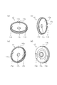
- 2 (a) to 2 (d) are perspective views of the seal plate.
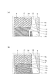
- FIG. 3A and FIG. 3B are explanatory diagrams for explaining the action of the protrusions.
- FIG. 3A is an enlarged view of an alternate long and short dash line portion in FIG. 1, and
- FIG. 3B shows a comparative example thereof.
- FIG. 4A and FIG. 4B are explanatory diagrams for explaining the shape of the protrusion in detail.
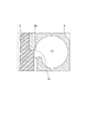
- FIG. 5 is an enlarged view of a broken line portion of FIG.
- FIG. 1 is a schematic cross-sectional view of a supercharger C according to the present embodiment.
- the arrow L shown in FIG. 1 will be described as a direction indicating the left side of the supercharger C
- the arrow R will be described as a direction indicating the right side of the supercharger C.
- the supercharger C includes a supercharger main body 1.
- the supercharger body 1 includes a bearing housing 2, a turbine housing 4 connected to the left side of the bearing housing 2 by a fastening bolt 3, and a compressor housing 6 connected to the right side of the bearing housing 2 by a fastening bolt 5. . These are integrated.
- the bearing housing 2 is formed with a bearing hole 2a that penetrates the supercharger C in the left-right direction.
- the bearing 7 is housed in the bearing hole 2a and rotatably supports the shaft 8.
- a turbine impeller 9 is integrally fixed to the left end portion of the shaft 8.
- the turbine impeller 9 is rotatably accommodated in the accommodating space in the turbine housing 4.
- a compressor impeller 10 is integrally fixed to the right end portion of the shaft 8.
- a housing space 11 is provided in the compressor housing 6.
- the accommodation space 11 opens on the right side of the supercharger C.
- the accommodation space 11 is connected to an air cleaner (not shown).
- the compressor impeller 10 is rotatably accommodated in the accommodation space 11.
- a turbine shaft is constituted by at least the shaft 8, the turbine impeller 9 and the compressor impeller 10.
- the bearing housing 2 and the compressor housing 6 have surfaces 2d and 6a that face each other in a state where the bearing housing 2 and the compressor housing 6 are connected by the fastening bolt 5.
- the surfaces 2d and 6a are referred to as opposing surfaces 2d and 6a.
- the facing surfaces 2d and 6a are separated from each other in the left-right direction in a state where the bearing housing 2 and the compressor housing 6 are connected.
- the opposing surfaces 2 d and 6 a form a diffuser flow path 12 that is located radially outside the compressor impeller 10.
- the diffuser flow path 12 pressurizes air (fluid) that has passed through the compressor impeller 10.
- the diffuser flow path 12 is formed in an annular shape from the radially inner side to the outer side of the shaft 8, and communicates with the housing space 11 via the compressor impeller 10 on the radially inner side.
- the compressor housing 6 is provided with a compressor scroll passage 13.
- the compressor scroll passage 13 is formed in an annular shape, and is located on the radially outer side of the shaft 8 with respect to the diffuser passage 12.
- the compressor scroll passage 13 communicates with an intake port (not shown) of the engine. Further, the compressor scroll passage 13 communicates with the diffuser passage 12. Therefore, when the compressor impeller 10 rotates, the air is sucked into the accommodating space 11 in the compressor housing 6 and is accelerated by the action of centrifugal force in the process of flowing between the blades of the compressor impeller 10, and the diameter of the diffuser passage 12 is increased.
- the air flows from the inner side to the outer side, and is further pressurized while being circulated in the compressor scroll passage 13 to be led to the intake port of the engine.
- a discharge port 14 is formed in the turbine housing 4.
- the discharge port 14 opens on the left side of the supercharger C and is connected to an exhaust gas purification device (not shown).
- the turbine housing 4 is provided with a flow path 15 and an annular turbine scroll flow path 16 positioned on the radially outer side of the shaft 8 (turbine impeller 9) with respect to the flow path 15.
- the turbine scroll passage 16 communicates with a gas inlet (not shown) through which exhaust gas discharged from an engine exhaust manifold (not shown) is guided.
- the turbine scroll passage 16 is also communicated with the passage 15 described above. Therefore, the exhaust gas of the engine is led from the gas inlet (not shown) to the turbine scroll passage 16 and is led to the discharge port 14 through the passage 15 and the turbine impeller 9. In this distribution process, the exhaust gas rotates the turbine impeller 9.
- the rotational force of the turbine impeller 9 is transmitted to the compressor impeller 10 via the shaft 8.
- the air is pressurized by the rotational force of the compressor impeller 10 generated by this transmission, and is guided to the intake port of the engine.
- a seal plate 17 is disposed on the back side of the compressor impeller 10 (the left side in FIG. 1, the side facing the bearing housing 2 when viewed from the compressor impeller 10).
- FIGS. 2A to 2C are perspective views mainly showing a surface 17a of the seal plate 17 on the compressor impeller 10 side.
- FIG. 2D is a perspective view mainly showing a back surface 17b of the seal plate 17 on the bearing 7 side.
- the seal plate 17 is a generally disk-shaped member having a size larger than that of the compressor impeller 10 when viewed from the left-right direction. That is, the seal plate 17 has a larger diameter than the compressor impeller 10.
- the seal plate 17 is provided with an insertion hole 17c through which the shaft 8 is inserted at the center in the radial direction.
- two bolt holes 17d penetrating in the same direction as the extending direction of the insertion hole 17c are provided on the radially outer side of the seal plate 17.
- a fastening bolt (not shown) is inserted through each bolt hole 17d.
- a fitting hole 2b is formed on the surface of the bearing housing 2 on the compressor impeller 10 side.
- the fitting hole 2b is recessed from this surface toward the bearing 7 side.
- the seal plate 17 is fitted into the fitting hole 2b.
- a screw hole (not shown) is formed in the bottom surface of the fitting hole 2b. This screw hole (not shown) is formed at a position facing the bolt hole 17d of the seal plate 17 when the seal plate 17 is fitted, and is screwed into a fastening bolt inserted into the bolt hole 17d. That is, the seal plate 17 is fitted in the fitting hole 2b and is fixed to the bearing housing 2 by the fastening bolt (not shown).
- the fastening bolt is a countersunk bolt.
- the seal plate 17 is in close contact with the bearing housing 2 so as to prevent the lubricating oil that has lubricated the bearing 7 accommodated in the bearing housing 2 from leaking to the compressor housing 6 side.
- the seal plate 17 has a surface 17a located on the compressor impeller 10 side.
- a protrusion 17e (extending portion) is formed on the surface 17a.
- the protrusion 17e is provided on the outer edge of the surface 17a located on the radially outer side. That is, the protrusion 17e is formed over the circumferential direction of the seal plate 17 except for a portion overlapping the bolt hole 17d.
- FIG. 3 (a) and 3 (b) are explanatory diagrams for explaining the action of the protrusion 17e.
- FIG. 3A is an enlarged view of an alternate long and short dash line portion in FIG. 1, and
- FIG. 3B shows a comparative example thereof.
- the bearing housing 2 has a facing surface 2d that faces the facing surface 6a of the compressor housing 6 and forms the diffuser flow path 12 together with the facing surface 6a.
- the opposing surface 2 d is separated from the radially inner end 2 e by the gap S in the radial direction of the shaft 8 from the outer peripheral edge 10 a of the compressor impeller 10.
- the inner peripheral surface 2 c forming the fitting hole 2 b of the bearing housing 2 and the outer peripheral edge 10 a of the compressor impeller 10 are separated from each other by the gap S in the radial direction of the shaft 8. That is, a gap S is formed between the radial inner end 2e (or the inner peripheral surface 2c) and the outer peripheral edge 10a in the radial direction of the shaft 8.
- the compressor impeller 10 is being reduced in size.
- the outer diameter of the seal plate 17 is limited in size reduction due to the problem of the strength of fixing to the bearing housing 2. Therefore, the gap S tends to increase. When the gap S becomes larger, it becomes easier for air flow to stagnate in the gap S portion, which becomes a cause of disturbance of the air flow toward the diffuser flow path 12 side.
- the protrusion 17e is positioned in the gap S as shown in FIG. That is, the protrusion 17e is provided at a portion of the seal plate 17 that faces the gap S.
- the protrusion 17e extends to the compressor housing 6 side from any portion 17f facing the back surface 10b of the compressor impeller 10. In other words, the protrusion 17e forms a step that protrudes toward the compressor housing 6 with respect to the portion 17f.
- the gap S can be made substantially smaller than in the comparative example.
- the radially outer space as viewed from the outer peripheral edge 10a of the compressor impeller 10 is filled with the protrusions 17e, and the distance between the outer peripheral edge 10a and the member positioned on the radially outer side of the outer peripheral edge 10a is reduced.
- FIG. 4 (a) and 4 (b) are explanatory views for explaining the shape of the protrusion 17e in detail.
- 4A is an enlarged view of a broken line portion of FIG. 3A
- FIG. 4B shows an example of another assembled state with respect to the cross section of the same portion as FIG. 4A.
- a tapered surface 2f is provided in a portion of the bearing housing 2 that forms the upstream inlet end (the radially inner end) of the diffuser flow path 12.
- the taper surface 2 f is provided at a portion that forms the inlet of the diffuser flow path 12 on the facing surface 2 d of the bearing housing 2.
- the taper surface 2f is inclined in a direction approaching the bearing 7 as it goes radially inward.
- An inclined surface 17 g is formed at the tip of the protrusion 17 e of the seal plate 17, that is, at a portion facing the compressor housing 6.
- the inclined surface 17g extends on an extension line (indicated by a one-dot chain line in FIG.
- the relative positional relationship between the seal plate 17 and the bearing housing 2 may be shifted due to the influence of the dimensional tolerance or fitting tolerance of each member.
- the part 2g is a part of the opposing surface (wall surface) 2d of the bearing housing 2 that forms the diffuser flow path 12 that is continuous from the tapered surface 2f to the downstream side (radially outside) of the diffuser flow path 12.
- the part 2g is a part located on the downstream side of the diffuser flow path 12 in the facing surface 2d and including (or forming) a boundary with the tapered surface 2f.
- the alternate long and short dash line is an extension of the part 2g.
- at least the end portion 17h does not protrude from the portion 2g (dashed line) of the bearing housing 2 even if it protrudes most toward the compressor housing 6 within the tolerance range. Is located.
- the end portion 17 h is a portion located on the innermost side in the radial direction at the tip of the protrusion 17 e of the seal plate 17.
- FIG. 5 is an enlarged view of the broken line portion of FIG.
- the end 2 h of the bearing housing 2 is more diffuser channel 12 (compressor scroll channel 13) than the end 6 b of the compressor housing 6. Protrudes to the side.
- the protrusion 17e is formed over the circumferential direction of the seal plate 17 except for the portion overlapping the bolt hole 17d has been described.
- the bolt hole 17d is formed more radially inward.
- the protrusion 17e may be formed over the entire circumference, or the width of the protrusion 17e in the circumferential direction may be further reduced.
- the protrusion 17e has been described as an example of the extending portion that extends to the compressor housing 6 side of the portion 17f of the seal plate 17 that faces the back surface 10b of the compressor impeller 10.
- the extending portion is not limited to the protrusion 17e having the shape shown in FIG. 2 (a) or FIG. 3 (a).
- the extending portion has a tapered surface continuously formed from a portion of the seal plate 17 facing the back surface 10b of the compressor impeller 10, and extends to the compressor housing 6 side from the portion 17f. It may be configured.
- the inclined surface 17g has been described as having a linear shape in the cross section shown in FIG. 4A.
- the inclined surface 17g may be curved in a curved shape.
- the case where the inclined surface 17g is provided on the protrusion 17e has been described.
- the tip of the protrusion 17e may not be formed as the inclined surface 17g.
- the air can be smoothly guided from the gap S toward the diffuser flow path 12 along the inclined surface 17g.
- the tapered surface 2f is provided on the bearing housing 2 (opposing surface 2d) has been described, but the tapered surface 2f may be omitted.
- the inclined surface 17g extends on the extended line of the tapered surface 2f.
- the inclined surface 17g may be arranged at a position shifted from the extended line of the tapered surface 2f.
- the radially inner end portion 17h of the inclined surface 17g is a portion 2g of the wall surface of the bearing housing 2 that forms the diffuser flow path 12 that is continuous radially outward from the tapered surface 2f.
- the case of offsetting to the bearing 7 side has been described.
- the front end surface of the protrusion 17e in the protruding direction may be arranged so as to be flush with the portion 2g.
- the seal plate 17 is not provided with the inclined surface 17g, the bearing housing 2 is not provided with the tapered surface 2f, and the flow path surface on the seal plate 17 side (or its tangent line) at the flow path outlet end of the compressor impeller 10 is provided.
- it may be formed so as to be parallel to the radial direction of the shaft 8. That is, the radially inner end 2e side of the facing surface 2d, the protruding end surface of the protrusion 17e, and the flow path surface on the seal plate 17 side of the flow path outlet end of the compressor impeller 10 are arranged on the same straight line. As a result, the disturbance of the flow toward the diffuser flow path 12 can be suppressed and air can be guided smoothly.
- the fastening bolt is a countersunk bolt.
- the fastening bolt is not limited to the countersunk bolt.
- a countersunk bolt as the fastening bolt, it is possible to reduce the step between the surface 17a of the seal plate 17 on the compressor impeller 10 side and the head of the fastening bolt.
- the present invention can be used for a supercharger in which the outer diameter of the compressor impeller is smaller than the outer diameter of the seal plate.
Landscapes
- Engineering & Computer Science (AREA)
- Mechanical Engineering (AREA)
- General Engineering & Computer Science (AREA)
- Chemical & Material Sciences (AREA)
- Combustion & Propulsion (AREA)
- Supercharger (AREA)
- Structures Of Non-Positive Displacement Pumps (AREA)
Abstract
Description
Claims (4)
- 軸受孔が形成されたベアリングハウジングと、
前記軸受孔に収容される軸受によって回転自在にシャフトが軸支され、該シャフトの一端側にタービンインペラが設けられ、該シャフトの他端側にコンプレッサインペラが設けられたタービン軸と、
前記ベアリングハウジングに連結され、内部に形成された収容空間に前記コンプレッサインペラを収容するコンプレッサハウジングと、
前記コンプレッサインペラよりも径方向外側に位置し、互いに対向する、前記コンプレッサハウジングと前記ベアリングハウジングの両対向面によって形成される環状のディフューザ流路と、
前記ベアリングハウジングに固定され、前記ディフューザ流路よりも径方向内側に位置し、前記コンプレッサインペラの背面に対向するように配置されるシールプレートと、
を備え、
前記ディフューザ流路を形成する前記ベアリングハウジングの対向面における径方向内側端と、前記コンプレッサインペラの外周縁との間には径方向に間隙が形成され、
前記シールプレートは、前記コンプレッサインペラよりも大径であって、前記間隙に臨む部位には、該コンプレッサインペラの背面に対向するいずれの部位よりも前記コンプレッサハウジング側に延在する延在部が設けられていることを特徴とする過給機。 - 前記延在部のうち、前記コンプレッサハウジングに対向する面は、径方向外側ほど該コンプレッサハウジングに近接する傾斜面となっていることを特徴とする請求項1に記載の過給機。
- 前記ベアリングハウジングのうち、前記ディフューザ流路の径方向内側の端部を形成する部位には、径方向内側に向かうにしたがって、前記軸受側に近接する向きに傾斜するテーパ面が設けられ、
前記傾斜面は、前記テーパ面の延長線上に延在することを特徴とする請求項2に記載の過給機。 - 前記傾斜面のうち、径方向内側の端部は、前記ディフューザ流路を形成する前記ベアリングハウジングの壁面のうち、前記テーパ面から径方向外側に連続する部位よりも、前記軸受側に位置していることを特徴とする請求項3に記載の過給機。
Priority Applications (5)
| Application Number | Priority Date | Filing Date | Title |
|---|---|---|---|
| JP2016519230A JP6311788B2 (ja) | 2014-05-16 | 2015-05-08 | 過給機 |
| KR1020167028161A KR101883417B1 (ko) | 2014-05-16 | 2015-05-08 | 과급기 |
| CN201580014816.2A CN106103939B (zh) | 2014-05-16 | 2015-05-08 | 增压器 |
| DE112015002306.2T DE112015002306T5 (de) | 2014-05-16 | 2015-05-08 | Turbolader |
| US15/269,068 US10408221B2 (en) | 2014-05-16 | 2016-09-19 | Turbocharger |
Applications Claiming Priority (2)
| Application Number | Priority Date | Filing Date | Title |
|---|---|---|---|
| JP2014-102739 | 2014-05-16 | ||
| JP2014102739 | 2014-05-16 |
Related Child Applications (1)
| Application Number | Title | Priority Date | Filing Date |
|---|---|---|---|
| US15/269,068 Continuation US10408221B2 (en) | 2014-05-16 | 2016-09-19 | Turbocharger |
Publications (1)
| Publication Number | Publication Date |
|---|---|
| WO2015174335A1 true WO2015174335A1 (ja) | 2015-11-19 |
Family
ID=54479876
Family Applications (1)
| Application Number | Title | Priority Date | Filing Date |
|---|---|---|---|
| PCT/JP2015/063288 Ceased WO2015174335A1 (ja) | 2014-05-16 | 2015-05-08 | 過給機 |
Country Status (6)
| Country | Link |
|---|---|
| US (1) | US10408221B2 (ja) |
| JP (1) | JP6311788B2 (ja) |
| KR (1) | KR101883417B1 (ja) |
| CN (1) | CN106103939B (ja) |
| DE (1) | DE112015002306T5 (ja) |
| WO (1) | WO2015174335A1 (ja) |
Cited By (3)
| Publication number | Priority date | Publication date | Assignee | Title |
|---|---|---|---|---|
| US20180073520A1 (en) * | 2016-09-13 | 2018-03-15 | Bosch Mahle Turbo Systems Gmbh & Co. Kg | Charging device |
| US11293450B2 (en) | 2018-05-25 | 2022-04-05 | Ihi Corporation | Centrifugal compressor |
| KR20220132576A (ko) * | 2020-04-15 | 2022-09-30 | 제이에프이 스틸 가부시키가이샤 | 에너지 수급 운용 가이던스 장치 및 제철소 내의 에너지 수급 운용 방법 |
Families Citing this family (10)
| Publication number | Priority date | Publication date | Assignee | Title |
|---|---|---|---|---|
| KR102676869B1 (ko) * | 2017-02-03 | 2024-06-19 | 한화파워시스템 주식회사 | 씨일이 구비된 밸런스 링을 이용하는 임펠러 |
| KR102552016B1 (ko) * | 2018-03-15 | 2023-07-05 | 현대자동차 주식회사 | 모터용 로터 조립체 |
| JP6950831B2 (ja) * | 2018-08-23 | 2021-10-13 | 株式会社Ihi | 遠心圧縮機 |
| KR102157885B1 (ko) | 2019-06-24 | 2020-09-21 | 엘지전자 주식회사 | 터보 압축기 |
| US11286780B2 (en) * | 2020-02-20 | 2022-03-29 | Hanwha Powersystems Co., Ltd | Sealing assembly for reducing thrust and turbomachine including the same |
| JP7384774B2 (ja) * | 2020-09-30 | 2023-11-21 | 株式会社神戸製鋼所 | ターボ圧縮機 |
| KR102934759B1 (ko) * | 2020-10-14 | 2026-03-04 | 한화에어로스페이스 주식회사 | 배기 덕트 어셈블리 및 이를 포함하는 비행체 |
| US11802488B2 (en) | 2021-09-10 | 2023-10-31 | Hamilton Sundstrand Corporation | Turbomachinery seal plate with variable lattice densities |
| US11773746B2 (en) | 2021-09-10 | 2023-10-03 | Hamilton Sundstrand Corporation | Turbomachinery rotor shroud with variable lattice densities |
| US11994141B2 (en) | 2021-09-10 | 2024-05-28 | Hamilton Sundstrand Corporation | Turbomachinery shaft with variable lattice densities |
Citations (2)
| Publication number | Priority date | Publication date | Assignee | Title |
|---|---|---|---|---|
| JP2002180841A (ja) * | 2000-12-14 | 2002-06-26 | Toyota Motor Corp | ターボコンプレッサ及びターボチャージャ |
| JP2003526037A (ja) * | 1998-10-01 | 2003-09-02 | アライドシグナル インコーポレイテッド | ばね負荷式ベーンディフューザ |
Family Cites Families (7)
| Publication number | Priority date | Publication date | Assignee | Title |
|---|---|---|---|---|
| US5297928A (en) * | 1992-06-15 | 1994-03-29 | Mitsubishi Jukogyo Kabushiki Kaisha | Centrifugal compressor |
| JP2005076463A (ja) | 2003-08-28 | 2005-03-24 | Shimizu Turbo Technology:Kk | ターボチャージャの軸受装置 |
| EP1816317B1 (en) * | 2006-02-02 | 2013-06-12 | IHI Corporation | Turbocharger with variable nozzle |
| JP2012067614A (ja) | 2010-09-21 | 2012-04-05 | Toyota Motor Corp | コンプレッサ出口圧力制御装置 |
| JP5998447B2 (ja) | 2011-09-30 | 2016-09-28 | 株式会社Ihi | 遠心圧縮機及び車両用過給機 |
| GB2499627A (en) * | 2012-02-23 | 2013-08-28 | Napier Turbochargers Ltd | Turbocharger casing |
| JP2013221454A (ja) | 2012-04-17 | 2013-10-28 | Ihi Corp | 遠心圧縮機 |
-
2015
- 2015-05-08 WO PCT/JP2015/063288 patent/WO2015174335A1/ja not_active Ceased
- 2015-05-08 CN CN201580014816.2A patent/CN106103939B/zh active Active
- 2015-05-08 KR KR1020167028161A patent/KR101883417B1/ko active Active
- 2015-05-08 DE DE112015002306.2T patent/DE112015002306T5/de active Pending
- 2015-05-08 JP JP2016519230A patent/JP6311788B2/ja active Active
-
2016
- 2016-09-19 US US15/269,068 patent/US10408221B2/en active Active
Patent Citations (2)
| Publication number | Priority date | Publication date | Assignee | Title |
|---|---|---|---|---|
| JP2003526037A (ja) * | 1998-10-01 | 2003-09-02 | アライドシグナル インコーポレイテッド | ばね負荷式ベーンディフューザ |
| JP2002180841A (ja) * | 2000-12-14 | 2002-06-26 | Toyota Motor Corp | ターボコンプレッサ及びターボチャージャ |
Cited By (4)
| Publication number | Priority date | Publication date | Assignee | Title |
|---|---|---|---|---|
| US20180073520A1 (en) * | 2016-09-13 | 2018-03-15 | Bosch Mahle Turbo Systems Gmbh & Co. Kg | Charging device |
| US11293450B2 (en) | 2018-05-25 | 2022-04-05 | Ihi Corporation | Centrifugal compressor |
| KR20220132576A (ko) * | 2020-04-15 | 2022-09-30 | 제이에프이 스틸 가부시키가이샤 | 에너지 수급 운용 가이던스 장치 및 제철소 내의 에너지 수급 운용 방법 |
| KR102914228B1 (ko) | 2020-04-15 | 2026-01-16 | 제이에프이 스틸 가부시키가이샤 | 에너지 수급 운용 가이던스 장치 및 제철소 내의 에너지 수급 운용 방법 |
Also Published As
| Publication number | Publication date |
|---|---|
| DE112015002306T5 (de) | 2017-02-09 |
| US20170002826A1 (en) | 2017-01-05 |
| CN106103939A (zh) | 2016-11-09 |
| KR101883417B1 (ko) | 2018-07-30 |
| US10408221B2 (en) | 2019-09-10 |
| JP6311788B2 (ja) | 2018-04-18 |
| JPWO2015174335A1 (ja) | 2017-04-20 |
| CN106103939B (zh) | 2018-08-28 |
| KR20160130496A (ko) | 2016-11-11 |
Similar Documents
| Publication | Publication Date | Title |
|---|---|---|
| JP6311788B2 (ja) | 過給機 | |
| JP6237056B2 (ja) | 遠心圧縮機および過給機 | |
| US10024361B2 (en) | Bearing structure and turbocharger | |
| JP6309651B2 (ja) | ターボ機械 | |
| JP6369621B2 (ja) | 遠心圧縮機および過給機 | |
| JP6234600B2 (ja) | タービン | |
| US9874140B2 (en) | Turbocharger | |
| WO2015128935A1 (ja) | シール構造及び該シール構造を備える過給機 | |
| JP6396512B2 (ja) | 過給機 | |
| JP6206592B2 (ja) | 軸受構造、および、過給機 | |
| WO2016088450A1 (ja) | インペラ、及び回転機械 | |
| US20190024577A1 (en) | Turbine housing and turbocharger | |
| JP7164346B2 (ja) | 回転機械及び過給機 | |
| WO2019225163A1 (ja) | 遠心圧縮機 | |
| CN112135975B (zh) | 离心压缩机 | |
| US20220178274A1 (en) | Turbocharger | |
| JP2025087955A (ja) | 遠心圧縮機のケーシング、遠心圧縮機及びターボチャージャ |
Legal Events
| Date | Code | Title | Description |
|---|---|---|---|
| 121 | Ep: the epo has been informed by wipo that ep was designated in this application |
Ref document number: 15793073 Country of ref document: EP Kind code of ref document: A1 |
|
| ENP | Entry into the national phase |
Ref document number: 2016519230 Country of ref document: JP Kind code of ref document: A |
|
| ENP | Entry into the national phase |
Ref document number: 20167028161 Country of ref document: KR Kind code of ref document: A |
|
| WWE | Wipo information: entry into national phase |
Ref document number: 112015002306 Country of ref document: DE |
|
| 122 | Ep: pct application non-entry in european phase |
Ref document number: 15793073 Country of ref document: EP Kind code of ref document: A1 |