WO2015166526A1 - ターゲット供給装置およびeuv光生成装置 - Google Patents
ターゲット供給装置およびeuv光生成装置 Download PDFInfo
- Publication number
- WO2015166526A1 WO2015166526A1 PCT/JP2014/061839 JP2014061839W WO2015166526A1 WO 2015166526 A1 WO2015166526 A1 WO 2015166526A1 JP 2014061839 W JP2014061839 W JP 2014061839W WO 2015166526 A1 WO2015166526 A1 WO 2015166526A1
- Authority
- WO
- WIPO (PCT)
- Prior art keywords
- gas
- pressure
- tank
- target
- euv light
- Prior art date
- Legal status (The legal status is an assumption and is not a legal conclusion. Google has not performed a legal analysis and makes no representation as to the accuracy of the status listed.)
- Ceased
Links
Images



Classifications
-
- G—PHYSICS
- G03—PHOTOGRAPHY; CINEMATOGRAPHY; ANALOGOUS TECHNIQUES USING WAVES OTHER THAN OPTICAL WAVES; ELECTROGRAPHY; HOLOGRAPHY
- G03F—PHOTOMECHANICAL PRODUCTION OF TEXTURED OR PATTERNED SURFACES, e.g. FOR PRINTING, FOR PROCESSING OF SEMICONDUCTOR DEVICES; MATERIALS THEREFOR; ORIGINALS THEREFOR; APPARATUS SPECIALLY ADAPTED THEREFOR
- G03F7/00—Photomechanical, e.g. photolithographic, production of textured or patterned surfaces, e.g. printing surfaces; Materials therefor, e.g. comprising photoresists; Apparatus specially adapted therefor
- G03F7/70—Microphotolithographic exposure; Apparatus therefor
- G03F7/70008—Production of exposure light, i.e. light sources
- G03F7/70033—Production of exposure light, i.e. light sources by plasma extreme ultraviolet [EUV] sources
-
- H—ELECTRICITY
- H05—ELECTRIC TECHNIQUES NOT OTHERWISE PROVIDED FOR
- H05G—X-RAY TECHNIQUE
- H05G2/00—Apparatus or processes specially adapted for producing X-rays, not involving X-ray tubes, e.g. involving generation of a plasma
- H05G2/001—Production of X-ray radiation generated from plasma
- H05G2/002—Supply of the plasma generating material
-
- H—ELECTRICITY
- H05—ELECTRIC TECHNIQUES NOT OTHERWISE PROVIDED FOR
- H05G—X-RAY TECHNIQUE
- H05G2/00—Apparatus or processes specially adapted for producing X-rays, not involving X-ray tubes, e.g. involving generation of a plasma
- H05G2/001—Production of X-ray radiation generated from plasma
- H05G2/009—Auxiliary arrangements not involved in the plasma generation
- H05G2/0094—Reduction, prevention or protection from contamination; Cleaning
-
- H—ELECTRICITY
- H10—SEMICONDUCTOR DEVICES; ELECTRIC SOLID-STATE DEVICES NOT OTHERWISE PROVIDED FOR
- H10P—GENERIC PROCESSES OR APPARATUS FOR THE MANUFACTURE OR TREATMENT OF DEVICES COVERED BY CLASS H10
- H10P76/00—Manufacture or treatment of masks on semiconductor bodies, e.g. by lithography or photolithography
Definitions
- the present disclosure relates to a target supply device and an EUV light generation device.
- an LPP Laser Produced Plasma
- DPP discharge Produced Plasma
- a target supply device is a target supply device that supplies a target material, a tank that stores the target material, a nozzle that is connected to the tank and outputs the target material, and the tank.
- a gas supply unit configured to supply gas, the gas supply unit being connected to a gas line, increasing the pressure of the gas supplied from the gas line, and supplying the pressure to the tank; and the pressure in the tank You may provide the pressure sensor to measure and the pressure controller which adjusts the pressure of the gas supplied to the said tank based on the measurement result in the said pressure sensor.
- An EUV light generation apparatus includes a target supply device that supplies a target material, and generates the EUV light by irradiating the target material with laser light, the target supply device
- the apparatus includes a tank that stores the target material, a nozzle that is connected to the tank and outputs the target material, and a gas supply unit that supplies gas to the tank.
- the gas supply unit is connected to a gas line.
- a pressure booster that boosts the gas supplied from the gas line and supplies the pressure to the tank; a pressure sensor that measures the pressure in the tank; and a measurement result of the pressure sensor, And a pressure controller for adjusting the pressure of the supplied gas.
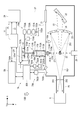
- FIG. 1 schematically shows a configuration of an LPP EUV light generation apparatus.
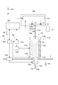
- FIG. 2 schematically shows a configuration of an EUV light generation apparatus including a target supply apparatus according to the first embodiment.
- FIG. 3 schematically shows the configuration of the booster.
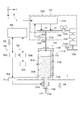
- FIG. 4 schematically shows a configuration of a target supply device that supplies gas to a tank using a gas cylinder.
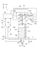
- FIG. 5 schematically shows a configuration of a target supply device according to the second embodiment.
- FIG. 6 schematically shows a configuration of a target supply device according to the third embodiment.
- FIG. 7 schematically shows a configuration of a target supply device according to the fourth embodiment.
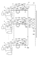
- FIG. 8 schematically shows a configuration of an EUV light generation system according to the fifth embodiment.
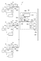
- FIG. 9 schematically shows a configuration of an EUV light generation system according to the sixth embodiment.
- a target supply device is a target supply device that supplies a target material, a tank that stores the target material, a nozzle that is connected to the tank and outputs the target material, A gas supply unit configured to supply a gas to the tank, the gas supply unit being connected to a gas line, boosting a gas supplied from the gas line, and supplying the gas to the tank; A pressure sensor that measures the pressure of the gas, and a pressure controller that adjusts the pressure of the gas supplied to the tank based on the measurement result of the pressure sensor.
- an EUV light generation apparatus includes a target supply device that supplies a target material, and generates EUV light by irradiating the target material with laser light
- the target supply device includes a tank that stores the target material, a nozzle that is connected to the tank and outputs the target material, and a gas supply unit that supplies gas to the tank.
- a pressure booster that boosts the gas supplied from the gas line and supplies the boosted gas to the tank, a pressure sensor that measures a pressure in the tank, and a measurement result of the pressure sensor, You may provide the pressure controller which adjusts the pressure of the gas supplied to a tank.
- FIG. 1 schematically shows a configuration of an exemplary LPP type EUV light generation system.
- the EUV light generation apparatus 1 may be used together with at least one laser apparatus 3.
- a system including the EUV light generation apparatus 1 and the laser apparatus 3 is referred to as an EUV light generation system 11.
- the EUV light generation apparatus 1 may include a chamber 2 and a target supply apparatus 7.
- the chamber 2 may be sealable.
- the target supply device 7 may be attached so as to penetrate the wall of the chamber 2, for example.
- the material of the target substance supplied from the target supply device 7 may include, but is not limited to, tin, terbium, gadolinium, lithium, xenon, or a combination of any two or more thereof.
- the wall of the chamber 2 may be provided with at least one through hole.
- a window 21 may be provided in the through hole, and the pulse laser beam 32 output from the laser device 3 may pass through the window 21.
- an EUV collector mirror 23 having a spheroidal reflecting surface may be disposed.
- the EUV collector mirror 23 may have first and second focal points.
- On the surface of the EUV collector mirror 23, for example, a multilayer reflective film in which molybdenum and silicon are alternately laminated may be formed.
- the EUV collector mirror 23 is preferably arranged such that, for example, the first focal point thereof is located in the plasma generation region 25 and the second focal point thereof is located at the intermediate focal point (IF) 292.
- a through hole 24 may be provided at the center of the EUV collector mirror 23, and the pulse laser beam 33 may pass through the through hole 24.
- the EUV light generation apparatus 1 may include an EUV light generation control unit 5, a target sensor 4, and the like.
- the target sensor 4 may have an imaging function and may be configured to detect the presence, locus, position, speed, and the like of the droplet 27 as a target.
- the EUV light generation apparatus 1 may include a connection unit 29 that allows the inside of the chamber 2 and the inside of the exposure apparatus 6 to communicate with each other.
- a wall 291 in which an aperture 293 is formed may be provided inside the connection portion 29.
- the wall 291 may be arranged such that its aperture 293 is located at the second focal position of the EUV collector mirror 23.
- the EUV light generation apparatus 1 may include a laser beam traveling direction control unit 34, a laser beam focusing mirror 22, a target recovery unit 28 for recovering the droplet 27, and the like.
- the laser beam traveling direction control unit 34 may include an optical element for defining the traveling direction of the laser beam and an actuator for adjusting the position, posture, and the like of the optical element.
- the pulsed laser beam 31 output from the laser device 3 passes through the window 21 as the pulsed laser beam 32 through the laser beam traveling direction control unit 34 and enters the chamber 2. May be.
- the pulsed laser beam 32 may travel through the chamber 2 along at least one laser beam path, be reflected by the laser beam collecting mirror 22, and irradiate at least one droplet 27 as the pulsed laser beam 33.
- the target supply device 7 may be configured to output the droplet 27 toward the plasma generation region 25 inside the chamber 2.
- the droplet 27 may be irradiated with at least one pulse included in the pulsed laser light 33.
- the droplet 27 irradiated with the pulsed laser light is turned into plasma, and radiation light 251 can be emitted from the plasma.
- the EUV light 252 included in the radiation light 251 may be selectively reflected by the EUV collector mirror 23.
- the EUV light 252 reflected by the EUV collector mirror 23 may be condensed at the intermediate condensing point 292 and output to the exposure apparatus 6.
- a single droplet 27 may be irradiated with a plurality of pulses included in the pulse laser beam 33.
- the EUV light generation controller 5 may be configured to control the entire EUV light generation system 11.
- the EUV light generation controller 5 may be configured to process the image data of the droplet 27 captured by the target sensor 4.
- the EUV light generation controller 5 may be configured to control, for example, the timing at which the droplet 27 is output, the output direction of the droplet 27, and the like.
- the EUV light generation control unit 5 may be configured to control, for example, the oscillation timing of the laser device 3, the traveling direction of the pulse laser light 32, the condensing position of the pulse laser light 33, and the like.
- the various controls described above are merely examples, and other controls may be added as necessary.
- the gas supply unit removes impurities from the gas boosted by the booster. May be further provided.
- the gas supply unit may further include a particle filter that removes particles from the gas boosted by the booster.
- the gas supply unit may further include a pressure stabilizer that stabilizes the pressure of the gas boosted by the booster.
- FIG. 2 schematically shows a configuration of an EUV light generation apparatus including a target supply apparatus according to the first embodiment.
- FIG. 3 schematically shows the configuration of the booster.
- the EUV light generation apparatus 1A may include a chamber 2 and a target supply apparatus 7A as shown in FIG.
- the target supply device 7A may include a target generation unit 70A and a target control device 80A.
- the laser device 3, the target sensor 4, and the EUV light generation control system 5A may be electrically connected to the target control device 80A.
- the target generation unit 70A may include a target generator 71A, a gas supply unit 73A, a temperature control unit 78A, and a piezo unit 79A.
- the target generator 71A may be made of a material having low reactivity with the target material 270 such as molybdenum.
- the target generator 71A may include a tank 711A for storing the target material 270 therein.
- the tank 711A may include a main body portion 712A, a bottom surface portion 713A, and a lid portion 714A.
- the main body 712A may be cylindrical.
- the bottom surface portion 713A may be configured to close the end portion on the + Z direction side as one end of the main body portion 712A in the axial direction.
- the bottom surface portion 713A may be formed integrally with the main body portion 712A.
- the lid portion 714A may be configured to close the end portion on the ⁇ Z direction side as the other end in the axial direction of the main body portion 712A.
- the lid 714A may be configured separately from the main body 712A.
- the lid 714A may be fixed to the main body 712A with a bolt (not shown). At this time, the gap between the main body 712A and the lid 714A may be sealed by fitting an O-ring (not shown) into a groove provided on the surface of the lid 714A on the + Z direction side.
- the tank 711 ⁇ / b> A may be provided with a nozzle 718 ⁇ / b> A for outputting the target material 270 in the tank 711 ⁇ / b> A as the droplet 27 into the chamber 2.
- the target generator 71 ⁇ / b> A may be provided such that the tank 711 ⁇ / b> A is located outside the chamber 2 and the nozzle 718 ⁇ / b> A is located inside the chamber 2.
- a nozzle hole 719A may be provided in the nozzle 718A.
- the nozzle hole 719A may open at a substantially central portion of the end on the + Z direction side of the nozzle 718A.
- the diameter of the nozzle hole 719A may be 3 ⁇ m to 15 ⁇ m.
- the nozzle 718A may be made of a material with low wettability with the target material 270.
- the material having low wettability with the target substance 270 may be a material having a contact angle with the target substance 270 exceeding 90 °.
- the material having a contact angle of 90 ° or more may be SiC, SiO 2 , Al 2 O 3 , molybdenum, tungsten, or tantalum.
- the preset output direction of the droplet 27 does not necessarily coincide with the gravity direction 10B.
- the output direction of the droplet 27 set in advance may be the central axis direction of the nozzle hole 719A, and is hereinafter referred to as a set output direction 10A.
- the droplet 27 may be configured to be output obliquely or horizontally with respect to the gravity direction 10B.
- the chamber 2 may be installed so that the set output direction 10A matches the gravity direction 10B.
- the lid 714A may be provided with a pipe 721A.
- the pipe 721A may be provided so as to pass through the lid portion 714A and the first end is located inside the tank 711A.
- the gas supply unit 73A may supply gas to the tank 711A via the pipe 721A.
- the purity of the gas supplied from the gas supply unit 73A to the tank 711A may be 99.999% or more.
- the gas supply unit 73A may include a booster 731A, a gas purifier 732A, a particle filter 733A, a buffer tank 734A as a pressure stabilizer, a pressure sensor 735A, and a pressure controller 736A.
- the booster 731A is, for example, an air driven gas such as model number AGT-7 / 30 (intake gas pressure: 1.0 MPa, discharge gas pressure: 20.7 MPa, flow rate: 0.07 L / min (Normal)) manufactured by HASKEL. It may be a booster.
- the booster 731A may be connected to the second end of the pipe 721A.
- the booster 731A may be connected to the gas line 730A via the pipe 722A.
- the gas line 730A may be a low-pressure gas line that can be installed in a factory at a low cost.
- the gas line 730A may supply a gas having a pressure of about 1 MPa.
- the gas supplied by the gas line 730A may be an inert gas such as argon, helium, nitrogen, or hydrogen.
- the booster 731A may boost the gas supplied from the gas line 730A and output the boosted gas to the pipe 721A.
- the booster 731A may include an air barrel 741A as shown in FIG.
- the air barrel 741A may be formed in a box shape.
- the air barrel 741A may include a cylindrical portion 742A, a first closing portion 743A, and a second closing portion 744A.
- the cylindrical portion 742A may be cylindrical.
- the first closing part 743A may close the upper end of the cylindrical part 742A.
- the first end of the pipe 745A and the first end of the pipe 746A may be connected to different positions in the first closing portion 743A.
- the pipes 745A and 746A may be connected so that the insides of the pipes 745A and 746A communicate with the inside of the air barrel 741A.
- a drive air supply unit 747A may be connected to the second end of the pipe 745A.
- a spool 748A may be connected to the second end of the pipe 746A.
- An exhaust pipe 749A may be connected to the spool 748A.
- the first pilot valve 750A may be provided at a position where the pipes 745A and 746A are not connected in the first closing portion 743A.
- the first pilot valve 750A may be provided such that a part of the first pilot valve 750A is located inside the air barrel 741A.
- the second closing part 744A may close the lower end of the cylindrical part 742A.
- a through hole 751A may be provided in the approximate center of the second closing portion 744A.
- the first end of the pipe 752A and the first end of the pipe 753A may be connected to different positions in the second closing portion 744A.
- the pipes 752A and 753A may be connected so that the insides of the pipes 752A and 753A communicate with the inside of the air barrel 741A.
- a drive air supply unit 747A may be connected to the second end of the pipe 752A.
- a spool 748A may be connected to the second end of the pipe 753A.
- a second pilot valve 754A may be provided at a position where the pipes 752A and 753A are not connected in the second closing portion 744A.
- the second pilot valve 754A may be provided such that a part of the second pilot valve 754A is located inside the air barrel 741A.
- the drive air supply unit 747A may supply drive air into the air barrel 741A via the pipe 745A or the pipe 752A.
- the spool 748A may exhaust the air inside the air barrel 741A via the exhaust pipe 749A via the pipe 746A or the pipe 753A.
- a gas barrel 755A may be provided in the second closing portion 744A of the air barrel 741A so as to extend downward.
- the gas barrel 755A may be formed integrally with the air barrel 741A.
- the gas barrel 755A may be formed in a cylindrical shape whose lower end is closed.
- the inner diameter of the gas barrel 755A may be smaller than the inner diameter of the cylindrical portion 742A.
- the gas barrel 755A may be provided so that the pipes 752A and 753A and the second pilot valve 754A are located outside the gas barrel 755A.
- the gas barrel 755A may be provided such that the center of the through hole 751A is located at the radial center of the gas barrel 755A.
- a first check valve 756A and a second check valve 764A may be provided at different positions on the side surface on the lower end side of the gas barrel 755A.
- the first check valve 756A may include a cylindrical main body 757A.
- the main body 757A may be provided to extend to the outside of the gas barrel 755A.
- the distal end side of the main body 757A may be connected to the gas line 730A via the pipe 722A.
- the inside of the main body 757A may communicate with the inside of the gas barrel 755A via a through hole 758A provided in the side surface of the gas barrel 755A.
- the inner diameter of the through hole 758A may be smaller than the inner diameter of the main body 757A.
- an annular spring contact portion 759A can be provided outside the through hole 758A.
- An inclined surface portion 760A may be provided on the distal end side of the main body portion 757A inside the main body portion 757A.
- the inclined surface portion 760A may have a shape in which the diameter dimension decreases as the distance from the gas barrel 755A increases.
- the through-hole 761A whose inner diameter is smaller than the inner diameter of the main body 757A can be provided at the tip of the main body 757A.
- a ball 762A may be disposed inside the main body 757A. The diameter of the ball 762A may be smaller than the inner diameter of the main body 757A and larger than the inner diameter of the through hole 761A.
- a spring 763A may be disposed inside the main body 757A.
- the spring 763A may be a coil spring.
- the spring 763A may be arranged such that one end side in the spiral axial direction is in contact with the spring contact portion 759A and the other end side is in contact with the ball 762A.
- the second check valve 764A may have the same configuration as the first check valve 756A.
- the second check valve 764A may include a main body portion 765A, a through hole 766A, an inclined surface portion 767A, a spring contact portion 768A, a through hole 769A, and a ball 770A.
- the main body 765A may be cylindrical.
- the distal end side of the main body portion 765A may be connected to the gas purifier 732A via the pipe 721A.
- the inside of the main body 765A may communicate with the inside of the gas barrel 755A via a through hole 766A provided on the side surface of the gas barrel 755A.
- An inclined surface portion 767A may be provided on the gas barrel 755A side inside the main body portion 765A.
- the inclined surface portion 767A may have a shape in which the diameter is reduced as it approaches the gas barrel 755A. Thereby, the inner diameter of the through hole 766A can be smaller than the inner diameter of the main body portion 765A.
- An annular spring contact portion 768A may be provided at the tip of the main body portion 765A.
- the opening of the spring contact portion 768A may be a through hole 769A having an inner diameter smaller than the inner diameter of the main body portion 765A.
- a ball 770A having a diameter smaller than the inner diameter of the main body 765A and larger than the inner diameter of the through hole 766A may be disposed inside the main body 765A.
- a spring 771A which is a coil spring, may be disposed inside the main body 765A. The spring 771A may be arranged such that one end side in the spiral axial direction is in contact with the spring contact portion 768A and the other end side is in contact with the ball 770A.
- the booster 731A may include an air piston 772A, a gas piston 773A, and a rod 774A.
- the air piston 772A may have a disk shape whose outer diameter is substantially the same as the inner diameter of the cylindrical portion 742A.
- the air piston 772A may be disposed in the cylindrical portion 742A so that the thickness direction of the air piston 772A is parallel to the axial direction of the cylindrical portion 742A.
- the drive air supplied to the first space 775A above the air piston 772A is inserted into a groove provided on the outer peripheral surface of the air piston 772A so that the drive air supplied to the first space 775A above the air piston 772A You may suppress leaking into 2 space 776A.
- the gas piston 773A may have a disk shape whose outer diameter is substantially the same as the inner diameter of the gas barrel 755A.
- the gas piston 773A may be disposed in the gas barrel 755A so that the thickness direction of the gas piston 773A is parallel to the axial direction of the gas barrel 755A.
- an O-ring (not shown) into a groove provided on the outer peripheral surface of the gas piston 773A, the gas in the third space 777A below the gas piston 773A is transferred to the fourth space 778A above the gas piston 773A. Leakage may be suppressed.
- the rod 774A may have a round bar shape whose outer diameter is substantially the same as the inner diameter of the through hole 751A.
- the rod 774A may be inserted through the through hole 751A.
- An air piston 772A may be connected to the upper end of the rod 774A.
- a gas piston 773A may be connected to the lower end of the rod 774A.
- the drive air in the second space 776A may be prevented from leaking into the fourth space 778A by fitting an O-ring (not shown) into the groove provided on the inner peripheral surface of the through hole 751A.
- the spool 748A is connected to the first space 775A and the outside of the booster 731A via the pipe 746A and the exhaust pipe 749A.
- the second space 776A may be sealed.
- the drive air supply unit 747A may supply drive air only to the second space 776A. As a result, the air in the first space 775A is exhausted, and the air piston 772A and the gas piston 773A are raised, and the pressure in the third space 777A can be lowered.
- the air piston 772A can contact the first pilot valve 750A as shown by a solid line in FIG.
- the spool 748A communicates the second space 776A and the outside of the booster 731A via the pipe 753A and the exhaust pipe 749A, and the first space 775A is sealed. It may be in a state.
- the drive air supply unit 747A may stop supplying drive air to the second space 776A and supply drive air only to the first space 775A.
- the gas purifier 732A may be provided on the tank 711A side from the booster 731A in the pipe 721A.
- the gas purifier 732A may remove impurities in the pressurized gas supplied from the booster 731A.
- the impurities in the pressurizing gas may be organic components such as lubricating oil mixed in the booster 731A, oxygen, or the like. Thereby, it can suppress that the target material 270 and the impurity in tank 711A react, and a reaction product generate
- the gas purifier 732A may be an adsorption or getter type gas purifier.
- the particle filter 733A may be provided on the tank 711A side from the gas purifier 732A in the pipe 721A.
- the particle filter 733A may remove particles in the pressurized gas output from the booster 731A.
- the particles in the pressurizing gas may be generated from a sliding component of the booster 731A.
- the sliding component that generates particles may be an O-ring provided on the gas piston 773A or a gas barrel 755A that contacts the O-ring. As a result, it is possible to prevent particles from entering the tank 711A and clogging the nozzle 718A.
- the particle filter 733A may be a clean gas filter having a filtration degree of about 0.02 ⁇ m.
- the filter medium of the particle filter 733A may be a PTFE membrane or the like.
- a pipe 723A may be connected to the tank 711A side of the particle filter 733A in the pipe 721A.
- a first end of the pipe 723A may be connected to a side surface of the pipe 721A.
- a buffer tank 734A may be provided at the second end of the pipe 723A.
- the volume of the buffer tank 734A may be larger than the capacity of all the gas flow paths from the booster 731A to the tank 711A.
- the buffer tank 734A may reduce the pressure fluctuation of the pressurizing gas generated in the pipe 721A. Since the pressure booster 731A pressurizes the gas by moving the gas piston 773A up and down, the pressure booster 731A can generate a pressure fluctuation of the pressure boosted gas that matches the reciprocating cycle of the gas piston 773A.
- the buffer tank 734A may reduce the pressure fluctuation of the boosted gas generated by the booster 731A.
- the pressure fluctuation range after reduction by the buffer tank 734A may be less than 10% of the pressure after adjustment by the
- a pipe 724A may be connected to the tank 711A side of the pipe 721A from the buffer tank 734A.
- a first end of the pipe 724A may be connected to a side surface of the pipe 721A.
- a pressure sensor 735A may be provided at the second end of the pipe 724A.
- the pressure sensor 735A may be electrically connected to a later-described valve control unit 737A of the pressure controller 736A.
- the pressure sensor 735A may measure the pressure in the pipe 724A and transmit a signal corresponding to the measured pressure to the valve control unit 737A.
- the pressure in the pipe 724A can be substantially the same as the pressure in the pipe 721A and the tank 711A. That is, the pressure sensor 735A can measure the pressure in the tank 711A.
- the pressure controller 736A may adjust the pressure of the pressurized gas supplied to the tank 711A based on the measurement result of the pressure sensor 735A.
- the pressure controller 736A may include a first valve V1, a second valve V2, and a valve control unit 737A.
- the 1st valve V1 may be provided between the connection part with piping 723A in piping 721A, and the connection part with piping 724A.
- a pipe 725A may be connected between a connection portion of the pipe 721A with the pipe 724A and the first valve V1.
- a first end of the pipe 725A may be connected to a side surface of the pipe 721A.
- a second end of the pipe 725A may be opened.
- the second valve V2 may be provided in the middle of the pipe 725A.
- the pipes 721A, 722A, 723A, 724A, and 725A may be formed of stainless steel, for example.
- the first valve V1 and the second valve V2 may be any one of a gate valve, a ball valve, a butterfly valve, and the like.
- the first valve V1 and the second valve V2 may be the same type of valve or different types of valves.
- a valve control unit 737A may be electrically connected to the first valve V1 and the second valve V2.
- the target control device 80A may transmit signals related to the first valve V1 and the second valve V2 to the valve control unit 737A.
- the opening and closing of the first valve V1 and the second valve V2 may be switched independently based on a signal transmitted from the valve control unit 737A.
- the pressurized gas supplied from the gas line 730A can be supplied into the tank 711A of the target generator 71A via the pipe 721A.
- the second valve V2 is closed, the pressurization gas existing in the pipe 721A and the tank 711A can be prevented from being discharged from the second end of the pipe 725A to the outside of the pipe 725A.
- the pressure in the tank 711A can be increased to the pressure after boosting in the booster 731A. Thereafter, the pressure in the tank 711A can be maintained at the pressure after the boosting by the booster 731A.
- the pressurized gas can be prevented from being supplied into the tank 711A via the pipe 721A.
- the second valve V2 is opened, a pressure difference between the inside of the pipe 721A and the tank 711A and the outside of the pipe 721A and the tank 711A causes the pressurized gas existing in the pipe 721A and the tank 711A to be 2 can be discharged to the outside of the pipe 725A. Accordingly, when the first valve V1 is closed and the second valve V2 is opened, the pressure in the tank 711A can be lowered.
- the temperature control unit 78A may be configured to control the temperature of the target material 270 in the tank 711A.
- the temperature control unit 78A may include a heater 781A, a heater power supply 782A, a temperature sensor 783A, and a temperature controller 784A.
- the heater 781A may be provided on the outer peripheral surface of the tank 711A.
- the heater power supply 782A may supply power to the heater 781A based on a signal from the temperature controller 784A to cause the heater 781A to generate heat. Thereby, the target material 270 in the tank 711A can be heated via the tank 711A.
- the temperature sensor 783A may be provided on the nozzle 718A side on the outer peripheral surface of the tank 711A, or may be provided in the tank 711A.
- the temperature sensor 783A may be configured to detect mainly the temperature of the installation position of the temperature sensor 783A in the tank 711A and a position in the vicinity thereof, and transmit a signal corresponding to the detected temperature to the temperature controller 784A.
- the temperature of the installation position of the temperature sensor 783A and the position in the vicinity thereof can be substantially the same as the temperature of the target material 270 in the tank 711A.
- the temperature controller 784A may be configured to output a signal for controlling the temperature of the target material 270 to a predetermined temperature based on a signal from the temperature sensor 783A to the heater power supply 782A.
- the piezo unit 79A may include a piezo element 791A and a power source 792A.
- the piezo element 791A may be provided on the outer peripheral surface of the nozzle 718A in the chamber 2. Instead of the piezo element 791A, a mechanism capable of applying vibration to the nozzle 718A at high speed may be provided.
- the power source 792A may be electrically connected to the piezo element 791A via the feedthrough 793A.
- the power source 792A may be electrically connected to the target control device 80A.
- the target generation unit 70A may be configured to generate the droplet 27 by generating the jet 27A by a continuous jet method and vibrating the jet 27A output from the nozzle 718A.
- FIG. 4 schematically shows a configuration of a target supply device that supplies gas to a tank using a gas cylinder.
- the operation of the target supply device 7A will be described by exemplifying the case where the target material 270 is tin.
- the target supply device shown in FIG. 4 is the same as the target supply device 7A of the first embodiment except that an inert gas cylinder 721 is used instead of the booster 731A, the gas purifier 732A, the particle filter 733A, and the buffer tank 734A.
- the target control device 80A transmits a signal to the temperature control unit 78A to heat the target material 270 in the target generator 71A to a predetermined temperature equal to or higher than the melting point of the target material 270. Also good.
- the target control device 80A may transmit a signal having a predetermined frequency to the piezo element 791A. Thereby, the piezo element 791A can vibrate so as to periodically generate the droplet 27 from the jet 27A.
- the target control apparatus 80A may transmit a signal to the valve control unit 737A and set the pressure in the tank 711A of the target generator 71A to the target pressure Pt.
- the valve control unit 737A may control the opening and closing of the first valve V1 and the second valve V2 so that the value of the difference ⁇ P between the pressure P measured by the pressure sensor 735A and the target pressure Pt becomes small.
- the inert gas in the inert gas cylinder 721 is supplied into the tank 711A, and the pressure in the tank 711A can be stabilized at the target pressure Pt.
- the jet 27A is output from the nozzle 718A, and the droplet 27 can be generated according to the vibration of the nozzle 718A.
- the distance between the droplets 27 In order to improve the stability of the EUV light output, it may be required to increase the distance between the droplets 27. If the distance between the droplets 27 is narrow, the influence of plasma for generating EUV light may disturb the trajectory of the droplet 27 that is next irradiated with the laser light. When the trajectory of the droplet 27 is disturbed, the laser beam is not irradiated to an appropriate position of the droplet 27, and the EUV light output may fluctuate. In order to suppress such a phenomenon, it can be considered that the distance between the droplets 27 is widened to reduce the influence of the plasma on the droplets 27 irradiated with the laser beam next time. For this reason, it is conceivable to reduce the repetition frequency of EUV light generation.
- the pressure to be supplied to the tank 711A may be about 12 MPa.
- the initial filling pressure of the inert gas cylinder 721 may be about 27 MPa.
- the inert gas cylinder 721 cannot supply the pressure necessary for the output of the droplet 27 to the tank 711A, and the inert gas cylinder 721 is replaced. May be necessary.
- the target supply device 7A may be configured as shown in FIG.
- the valve controller 737A of the pressure controller 736A performs opening / closing control of the first valve V1 and the second valve V2 in order to reach the target pressure Pt in the tank 711A
- the booster 731A may boost the gas supplied from the gas line 730A and supply it to the pressure controller 736A.
- the gas in the gas line 730A is filled in the third space 777A, the gas piston 773A of the booster 731A is raised to the position shown by the solid line in FIG. 3, and the air piston 772A is the first pilot valve.
- the booster 731A may lower the air piston 772A and the gas piston 773A. Accordingly, the first check valve 756A is closed and the second check valve 764A is opened, and the gas in the third space 777A can be pressurized and supplied to the pressure controller 736A.
- the booster 731A controls the air piston 772A and the gas piston 773A so that the flow rate of the boosted gas supplied to the pressure controller 736A via the second check valve 764A is about 2.33 L / min (Normal). It may be lowered. This can be assumed to be completed in 12 hours when the pressure of about 1 MPa is increased to about 14 MPa and the volume to be increased is set to 12 L.
- the volume to be boosted may be assumed that the capacity of a typical buffer tank 734A is 10L and the capacity of the tank 711A and the pipes 721A, 723A, and 724A is 2L.
- the output of the droplet 27 may be stopped, and the pressure in the tank 711A may be about 1 atmosphere (0.1 MPa).
- the volume to be boosted with respect to the initial pressure increase can be 2L.
- the flow rate of the pressure increase gas supplied to the pressure controller 736A may be 0.39 L / min (Normal). That is, during the preparation of the output of the droplet 27, the booster 731A supplies a pressure-increasing gas of about 12 MPa to the pressure controller 736A at a flow rate of 0.35 L / min (Normal) or more and 2.4 L / min (Normal) or less. May be.
- the pressurization gas supplied from the booster 731A can be supplied to the gas purifier 732A.
- the pressurized gas supplied to the gas purifier 732A can be supplied to the particle filter 733A after removing impurities in the gas purifier 732A.
- the pressurized gas supplied to the particle filter 733A can be supplied to the buffer tank 734A and the pressure controller 736A after the particles are removed in the particle filter 733A.
- the pressure fluctuation of the pressurized gas supplied to the pressure controller 736A can be reduced in the buffer tank 734A.
- the pressure controller 736A may adjust the pressure of the pressurization gas with reduced pressure fluctuation and supply it to the tank 711A. When the pressure in the tank 711A reaches the target pressure Pt, the jet 27A is output from the nozzle 718A, and the droplet 27 can be generated.
- the consumption of the pressurized gas in the pressure controller 736A can be 9.44 cc / min (Normal).
- the amount of boosted gas consumed in this case may be the amount of boosted gas discharged from the pipe 725A when the second valve V2 of the pressure controller 736A is opened.
- the consumption of the pressurized gas in the pressure controller 736A can be 12.44 cc / min (Normal).
- the consumption of this pressurizing gas may be assumed to be a case where a tin droplet 27 having a diameter of 20 ⁇ m is output at 100 kHz with a pressure of 12 MPa.
- the booster 731A supplies a pressurized gas of about 12 MPa to a flow rate of 9.4 cc / min (Normal) to 12.5 cc / min (Normal). May be supplied to the pressure controller 736A.
- the air piston 772A and the gas piston 773A of the booster 731A can be lowered. Thereby, even if the droplet 27 continues to be output and the pressurized gas is consumed, the pressure in the tank 711A can be maintained at the target pressure Pt.
- the booster 731A may raise the air piston 772A and the gas piston 773A.
- the second check valve 764A is closed to stop the supply of the pressurized gas, and the first check valve 756A is opened, so that the gas in the gas line 730A can be supplied into the third space 777A.
- the booster 731A lowers the air piston 772A and the gas piston 773A as described above, and the pressure controller
- the supply of the pressurized gas to 736A may be resumed.
- the time from when the booster 731A stops supplying the boosted gas to when it restarts is the time when the droplet 27 is output during this time and the pressure gas continues to be consumed.
- the length maintained at the target pressure Pt may be used.
- the booster 731A boosts the gas in the gas line 730A and supplies it to the pressure controller 736A, so that the high-pressure boosted gas is stored in the tank. It may be possible to continue to supply to 711A. As a result, it is possible to increase the speed of the droplet 27 without exchanging the inert gas cylinder.
- the gas in the gas line 730A that can be installed at a low cost in the factory is supplied after being pressurized, the cost can be suppressed and safety management of the high-pressure gas facility can be unnecessary.
- the pressure controller 736A can perform highly accurate pressure control. As a result, output stability such as the speed, interval, and output angle of the droplet 27 can be improved.
- FIG. 5 schematically shows a configuration of a target supply device according to the second embodiment.
- the target supply device 7B of the second embodiment may apply the same configuration as the target supply device 7A of the first embodiment except for the gas supply unit 73B.
- the gas supply unit 73B may be the same as the gas supply unit 73A of the first embodiment, except that the gas supply unit 73B further includes a booster 731B similar to the booster 731A.
- the booster 731B may be provided between the booster 731A and the gas purifier 732A in the pipe 721A.
- the booster 731A boosts the gas supplied from the gas line 730A to increase the pressure. You may supply to the container 731B.
- the booster 731B may further boost the boosted gas from the booster 731A.
- the boosted gas boosted by the booster 731B can be supplied to the pressure controller 736A via the gas purifier 732A, the particle filter 733A, and the buffer tank 734A.
- the pressure controller 736A can be supplied with a pressure-increasing gas having a pressure higher than that in the first embodiment.
- FIG. 6 schematically illustrates the configuration of a target supply device according to a third embodiment.
- the target supply device 7C of the third embodiment may apply the same configuration as the target supply device 7A of the first embodiment except for the gas supply unit 73C.
- the gas supply unit 73C may be the same as the gas supply unit 73A of the first embodiment except that a pressure regulator 738C as a pressure stabilizer is provided instead of the buffer tank 734A.
- the pressure regulator 738C may be provided between the particle filter 733A and the first valve V1 in the pipe 721A.
- the pipe 723A may not be connected to the pipe 721A.
- the material of the diaphragm of the pressure regulator 738C may be PTFE (polytetrafluoroethylene), EPM (ethylene propylene rubber), EPDM (ethylene propylene diene rubber), fluorine rubber, or the like.
- the pressure regulator 738C may reduce pressure fluctuation that occurs in the pipe 721A.
- the pressure fluctuation range after reduction by the pressure regulator 738C may be less than 10% of the pressure after adjustment by the pressure controller 736A.
- the pressure regulator 738C instead of the buffer tank 734A, the volume of the configuration used for reducing the pressure fluctuation can be reduced.
- the booster 731A may boost the gas supplied from the gas line 730A.
- the boosted gas boosted by the booster 731A can be supplied to the pressure regulator 738C via the gas purifier 732A and the particle filter 733A.
- the pressure regulator 738C may reduce the pressure fluctuation of the pressurizing gas.
- the pressure controller 736A can be supplied with the boosted gas with reduced pressure fluctuations, as in the first embodiment.
- FIG. 7 schematically illustrates the configuration of a target supply device according to a fourth embodiment.
- the target supply device 7D of the fourth embodiment may apply the same configuration as the target supply device 7A of the first embodiment except for the gas supply unit 73D.
- the gas supply unit 73D may be the same as the gas supply unit 73A of the first embodiment except that a purifier 739D is provided instead of the gas purifier 732A and the particle filter 733A.
- the purifier 739D may be provided between the connection portion of the pipe 723A in the pipe 721A and the booster 731A.
- the purifier 739D may be, for example, model number SP70-203 (pressure resistance: 206.8 atm (about 21.0 MPa), filtration degree of particle filter: 0.003 ⁇ m) manufactured by SAES Pure Gas.
- the booster 731A may boost the gas supplied from the gas line 730A. .
- the boosted gas boosted by the booster 731A can be supplied to the purifier 739D.
- the purifier 739D may remove impurities and particles in the pressurized gas.
- the pressurized gas from which impurities and particles have been removed can be supplied to the tank 711A via the buffer tank 734A and the pressure controller 736A.
- FIG. 8 schematically illustrates a configuration of an EUV light generation system according to a fifth embodiment.
- the EUV light generation system 11E of the fifth embodiment may include a plurality of EUV light generation apparatuses 1E and fewer gas supply units 73A than the number of EUV light generation apparatuses 1E.
- Each EUV light generation apparatus 1 ⁇ / b> E may be used together with the laser apparatus 3 and the exposure apparatus 6.
- the EUV light generation apparatus 1E may apply the same configuration as the EUV light generation apparatus 1A of the first embodiment except for the target supply apparatus 7E.
- the target supply device 7E may apply the same configuration as the target supply device 7A of the first embodiment except that the gas supply unit 73A is not individually provided.
- a pipe 901E may be provided on the lid 714A of the target generator 71A.
- the pipe 901E may pass through the lid 714A, and the first end may be located inside the tank 711A.
- a valve V3 may be provided in the middle of the pipe 901E.
- only one gas supply unit 73A may be provided.
- the pipe 902E may be connected to the first end of the pipe 721A so as to branch into the same number as the EUV light generation apparatus 1E.
- a valve V4 may be provided in the middle of the branching of the pipe 902E.
- the 2nd end of piping 902E and the 2nd end of piping 901E may be connected via joint 911E.
- the pressurization gas in the pipe 721A can be supplied into the tanks 711A of the plurality of EUV light generation apparatuses 1E.
- closing the valve V3 and the valve V4 and operating the joint 911E to release the connection between the pipe 901E and the pipe 902E it may be possible to individually remove and maintain the target supply device 7E.
- the worker opens the valve V3 and the valve V4 connected to the EUV light generation apparatus 1E that generates EUV light among the plurality of EUV light generation apparatuses 1E configuring the EUV light generation system 11E, and opens the tank 711A. It is good also as a state which can supply pressurization gas.
- the pressure controller 736A controls the pressure so that the pressure in the tank 711A reaches the target pressure Pt
- the booster 731A boosts the gas supplied from the gas line 730A. May be.
- the pressurized gas boosted by the booster 731A can be supplied to the pressure controller 736A via the gas purifier 732A, the particle filter 733A, and the buffer tank 734A.
- the pressurized gas whose pressure is adjusted by the pressure controller 736A can be supplied to the tank 711A of the EUV light generation apparatus 1E in which the valve V3 and the valve V4 are open.
- the pressure in the tank 711A reaches the target pressure Pt, the jet 27A is output from the nozzle 718A, and the droplet 27 can be generated.
- one gas supply The unit 73A can supply the pressurized gas capable of outputting the droplet 27 to the plurality of tanks 711A.
- the number of gas supply units 73A may be less than the number of tanks 711A, and the cost may be reduced.
- the target supply device 7E is individually removed for maintenance, it may be unnecessary to stop the operation of the other target supply devices 7E.
- FIG. 9 schematically illustrates a configuration of an EUV light generation system according to a sixth embodiment.
- the EUV light generation system 11F of the sixth embodiment may include a plurality of EUV light generation apparatuses 1F and gas supply units 73F that are fewer than the number of EUV light generation apparatuses 1F.
- Each EUV light generation apparatus 1 ⁇ / b> F may be used together with the laser apparatus 3 and the exposure apparatus 6.
- the EUV light generation apparatus 1F may be the same as the EUV light generation apparatus 1A of the first embodiment except for the target supply apparatus 7F.
- the target supply device 7F may be the same as the target supply device 7A of the first embodiment, except that the gas supply unit 73F is not individually provided.
- a pipe 901E may be provided on the lid 714A of the target generator 71A so that the first end is located inside the tank 711A.
- a valve V3 may be provided in the middle of the pipe 901E.
- the gas supply unit 73F may include a booster 731A, a gas purifier 732A, a particle filter 733A, a buffer tank 734A, a pressure sensor 735A, and a pressure controller 736A.
- the number of boosters 731A, gas purifiers 732A, particle filters 733A, and buffer tanks 734A may be one each.
- the number of pressure sensors 735A and pressure controllers 736A may be the same as the number of EUV light generation apparatuses 1F, respectively.
- the booster 731A may be connected to the second end of the pipe 721A.
- the booster 731A may be connected to the gas line 730A via the pipe 722A.
- a gas purifier 732A, a particle filter 733A, and a buffer tank 734A may be provided in the pipe 721A.
- the pipe 902E may be connected to the first end of the pipe 721A so as to branch into the same number as the EUV light generation apparatus 1F.
- a valve V4 may be provided in the middle of the branching of the pipe 902E.
- the 2nd end of piping 902E and the 2nd end of piping 901E may be connected via joint 911E.
- a first end of the pipe 903F may be connected between the valve V3 and the lid 714A in the pipe 901E.
- a pressure sensor 735A may be provided at the second end of the pipe 903F.
- the first valve V1 of the pressure controller 736A may be provided between the pipe 721A side and the valve V4 after the branching of the pipe 902E.
- a first end of the pipe 904F may be connected between the first valve V1 and the valve V4 in the pipe 902E.
- the second valve V2 of the pressure controller 736A may be provided in the middle of the pipe 904F.
- the second end of the pipe 904F may be opened.
- the first valve V1 and the second valve V2 may be electrically connected to the valve controller 737A of the pressure controller 736A.
- the pressure sensor 735A may be electrically connected to the valve control unit 737A by the electric wire 911F and the electric wire 912F that are electrically connected via the connector 913F.
- the pressurized gas in the pipe 721A can be supplied into the tanks 711A of the plurality of EUV light generation apparatuses 1F. Further, by closing the valve V3 and the valve V4, the joint 911E is operated to release the connection between the pipe 902E and the pipe 901E, and the connector 913F is operated to release the connection between the electric wire 911F and the electric wire 912F.
- the target supply device 7F may be individually removed for maintenance.
- the worker opens the valve V3 and the valve V4 connected to the EUV light generation apparatus 1F that generates EUV light among the plurality of EUV light generation apparatuses 1F constituting the EUV light generation system 11F, and enters the tank 711A. It is good also as a state which can supply pressurization gas.
- the target control device 80A of the EUV light generation apparatus 1F that generates EUV light may transmit a signal to the valve control unit 737A to set the pressure in the tank 711A to the target pressure Pt.
- the target pressure Pt of each tank 711A may be the same or different.
- a plurality of target generators 71A having different diameters of the nozzle holes 719A may be used to output the droplets 27 at the same speed, or a plurality of nozzle holes 719A having the same diameter may be used.
- the target generator 71A may be used to output the droplets 27 at different speeds.
- the booster 731A may boost the gas supplied from the gas line 730A in order to make the pressure in the tank 711A reach the target pressure Pt.
- the pressurized gas can be supplied to the tank 711A of the EUV light generation apparatus 1F in which the valve V3 and the valve V4 are open.
- the jet 27A is output from the nozzle 718A, and the droplet 27 can be generated.
- the booster 731A may use a configuration in which the pressure in the third space 777A is detected by a pressure sensor and the air piston 772A and the gas piston 773A are moved up and down by driving a motor.
- a booster that raises and lowers the air piston 772A and the gas piston 773A with drive air is referred to as a “boost of the embodiment”
- a booster that raises and lowers the air piston 772A and the gas piston 773A with the drive of the motor It may be referred to as an “example booster”.
- three or more boosters may be provided.
- two or more boosters may be provided.
- a plurality of boosters are provided, only the booster of the embodiment may be provided, or only the booster of the modified example may be provided, or both the booster of the embodiment and the booster of the modified example may be provided. Good.
- the buffer tank 734A and the pressure regulator 738C are installed. It does not have to be provided.
- a pressure regulator 738C may be provided instead of the buffer tank 734A.
- at least one of the gas purifier 732A and the particle filter 733A may not be provided, and the arrangement positions of the gas purifier 732A and the particle filter 733A are switched. Also good.
- a purifier 739D may be provided instead of the gas purifier 732A and the particle filter 733A. In the fourth embodiment, the purifier 739D may not be provided.
Landscapes
- Physics & Mathematics (AREA)
- Engineering & Computer Science (AREA)
- Plasma & Fusion (AREA)
- Optics & Photonics (AREA)
- General Physics & Mathematics (AREA)
- Exposure And Positioning Against Photoresist Photosensitive Materials (AREA)
- X-Ray Techniques (AREA)
Abstract
ターゲット供給装置(7A)は、ターゲット物質(270)を貯蔵するタンク(711A)と、タンク(711A)に接続され、ターゲット物質(270)を出力するノズル(718A)と、タンク(711A)にガスを供給するガス供給部(73A)とを備え、ガス供給部(73A)は、ガスライン(730A)に接続され、ガスライン(730A)から供給されるガスを昇圧してタンク(711A)に出力する昇圧器(731A)と、タンク(711A)内の圧力を計測する圧力センサ(735A)と、圧力センサ(735A)での計測結果に基づいて、タンク(711A)に供給されるガスの圧力を調整する圧力コントローラ(736A)とを備えてもよい。
Description
本開示は、ターゲット供給装置およびEUV光生成装置に関する。
近年、半導体プロセスの微細化に伴って、半導体プロセスの光リソグラフィにおける転写パターンの微細化が急速に進展している。次世代においては、45nm~70nmの微細加工、さらには32nm以下の微細加工が要求されるようになる。このため、例えば32nm以下の微細加工の要求に応えるべく、波長13nm程度の極端紫外(EUV)光を生成するための装置と縮小投影反射光学系とを組み合わせた露光装置の開発が期待されている。
EUV光生成装置としては、ターゲット物質にレーザ光を照射することによって生成されるプラズマが用いられるLPP(Laser Produced Plasma)式の装置と、放電によって生成されるプラズマが用いられるDPP(Discharge Produced Plasma)式の装置と、軌道放射光が用いられるSR(Synchrotron Radiation)式の装置との3種類の装置が提案されている。
本開示の一態様によるターゲット供給装置は、ターゲット物質を供給するターゲット供給装置であって、前記ターゲット物質を貯蔵するタンクと、前記タンクに接続され、前記ターゲット物質を出力するノズルと、前記タンクにガスを供給するガス供給部とを備え、前記ガス供給部は、ガスラインに接続され、前記ガスラインから供給されるガスを昇圧して前記タンクに供給する昇圧器と、前記タンク内の圧力を計測する圧力センサと、前記圧力センサでの計測結果に基づいて、前記タンクに供給されるガスの圧力を調整する圧力コントローラとを備えてもよい。
本開示の一態様によるEUV光生成装置は、ターゲット物質を供給するターゲット供給装置を備え、前記ターゲット物質にレーザ光を照射することによってEUV光を生成するEUV光生成装置であって、前記ターゲット供給装置は、前記ターゲット物質を貯蔵するタンクと、前記タンクに接続され、前記ターゲット物質を出力するノズルと、前記タンクにガスを供給するガス供給部とを備え、前記ガス供給部は、ガスラインに接続され、前記ガスラインから供給されるガスを昇圧して前記タンクに供給する昇圧器と、前記タンク内の圧力を計測する圧力センサと、前記圧力センサでの計測結果に基づいて、前記タンクに供給されるガスの圧力を調整する圧力コントローラとを備えてもよい。
本開示のいくつかの実施形態を、単なる例として、添付の図面を参照して以下に説明する。
図1は、LPP方式のEUV光生成装置の構成を概略的に示す。
図2は、第1実施形態に係るターゲット供給装置を含むEUV光生成装置の構成を概略的に示す。
図3は、昇圧器の構成を概略的に示す。
図4は、ガスボンベを用いてタンクにガスを供給するターゲット供給装置の構成を概略的に示す。
図5は、第2実施形態に係るターゲット供給装置の構成を概略的に示す。
図6は、第3実施形態に係るターゲット供給装置の構成を概略的に示す。
図7は、第4実施形態に係るターゲット供給装置の構成を概略的に示す。
図8は、第5実施形態に係るEUV光生成システムの構成を概略的に示す。
図9は、第6実施形態に係るEUV光生成システムの構成を概略的に示す。
内容
1.概要
2.EUV光生成装置の全体説明
2.1 構成
2.2 動作
3.ターゲット供給装置を含むEUV光生成装置
3.1 用語の説明
3.2 第1実施形態
3.2.1 概略
3.2.2 構成
3.2.3 動作
3.3 第2実施形態
3.3.1 構成
3.3.2 動作
3.4 第3実施形態
3.4.1 構成
3.4.2 動作
3.5 第4実施形態
3.5.1 構成
3.5.2 動作
3.6 第5実施形態
3.6.1 構成
3.6.2 動作
3.7 第6実施形態
3.7.1 構成
3.7.2 動作
3.8 変形例
1.概要
2.EUV光生成装置の全体説明
2.1 構成
2.2 動作
3.ターゲット供給装置を含むEUV光生成装置
3.1 用語の説明
3.2 第1実施形態
3.2.1 概略
3.2.2 構成
3.2.3 動作
3.3 第2実施形態
3.3.1 構成
3.3.2 動作
3.4 第3実施形態
3.4.1 構成
3.4.2 動作
3.5 第4実施形態
3.5.1 構成
3.5.2 動作
3.6 第5実施形態
3.6.1 構成
3.6.2 動作
3.7 第6実施形態
3.7.1 構成
3.7.2 動作
3.8 変形例
以下、本開示の実施形態について、図面を参照しながら詳しく説明する。以下に説明される実施形態は、本開示のいくつかの例を示すものであって、本開示の内容を限定するものではない。また、各実施形態で説明される構成および動作の全てが本開示の構成および動作として必須であるとは限らない。また、図1以外の図面を用いて説明する実施形態において、図1に示す構成要素のうち、本開示の説明に必須でない構成については、図示を省略する場合がある。なお、同一の構成要素には同一の参照符号を付して、重複する説明を省略する。
1.概要
本開示の実施形態においては、ターゲット供給装置は、ターゲット物質を供給するターゲット供給装置であって、前記ターゲット物質を貯蔵するタンクと、前記タンクに接続され、前記ターゲット物質を出力するノズルと、前記タンクにガスを供給するガス供給部とを備え、前記ガス供給部は、ガスラインに接続され、前記ガスラインから供給されるガスを昇圧して前記タンクに供給する昇圧器と、前記タンク内の圧力を計測する圧力センサと、前記圧力センサでの計測結果に基づいて、前記タンクに供給されるガスの圧力を調整する圧力コントローラとを備えてもよい。
本開示の実施形態においては、ターゲット供給装置は、ターゲット物質を供給するターゲット供給装置であって、前記ターゲット物質を貯蔵するタンクと、前記タンクに接続され、前記ターゲット物質を出力するノズルと、前記タンクにガスを供給するガス供給部とを備え、前記ガス供給部は、ガスラインに接続され、前記ガスラインから供給されるガスを昇圧して前記タンクに供給する昇圧器と、前記タンク内の圧力を計測する圧力センサと、前記圧力センサでの計測結果に基づいて、前記タンクに供給されるガスの圧力を調整する圧力コントローラとを備えてもよい。
本開示の実施形態においては、EUV光生成装置は、ターゲット物質を供給するターゲット供給装置を備え、前記ターゲット物質にレーザ光を照射することによってEUV光を生成するEUV光生成装置であって、前記ターゲット供給装置は、前記ターゲット物質を貯蔵するタンクと、前記タンクに接続され、前記ターゲット物質を出力するノズルと、前記タンクにガスを供給するガス供給部とを備え、前記ガス供給部は、ガスラインに接続され、前記ガスラインから供給されるガスを昇圧して前記タンクに供給する昇圧器と、前記タンク内の圧力を計測する圧力センサと、前記圧力センサでの計測結果に基づいて、前記タンクに供給されるガスの圧力を調整する圧力コントローラとを備えてもよい。
2.EUV光生成装置の全体説明
2.1 構成
図1に、例示的なLPP式のEUV光生成システムの構成を概略的に示す。EUV光生成装置1は、少なくとも1つのレーザ装置3と共に用いられてもよい。本願においては、EUV光生成装置1およびレーザ装置3を含むシステムを、EUV光生成システム11と称する。図1に示し、かつ、以下に詳細に説明するように、EUV光生成装置1は、チャンバ2、ターゲット供給装置7を含んでもよい。チャンバ2は、密閉可能であってもよい。ターゲット供給装置7は、例えば、チャンバ2の壁を貫通するように取り付けられてもよい。ターゲット供給装置7から供給されるターゲット物質の材料は、スズ、テルビウム、ガドリニウム、リチウム、キセノン、又は、それらの内のいずれか2つ以上の組合せを含んでもよいが、これらに限定されない。
2.1 構成
図1に、例示的なLPP式のEUV光生成システムの構成を概略的に示す。EUV光生成装置1は、少なくとも1つのレーザ装置3と共に用いられてもよい。本願においては、EUV光生成装置1およびレーザ装置3を含むシステムを、EUV光生成システム11と称する。図1に示し、かつ、以下に詳細に説明するように、EUV光生成装置1は、チャンバ2、ターゲット供給装置7を含んでもよい。チャンバ2は、密閉可能であってもよい。ターゲット供給装置7は、例えば、チャンバ2の壁を貫通するように取り付けられてもよい。ターゲット供給装置7から供給されるターゲット物質の材料は、スズ、テルビウム、ガドリニウム、リチウム、キセノン、又は、それらの内のいずれか2つ以上の組合せを含んでもよいが、これらに限定されない。
チャンバ2の壁には、少なくとも1つの貫通孔が設けられていてもよい。その貫通孔には、ウインドウ21が設けられてもよく、ウインドウ21をレーザ装置3から出力されるパルスレーザ光32が透過してもよい。チャンバ2の内部には、例えば、回転楕円面形状の反射面を有するEUV集光ミラー23が配置されてもよい。EUV集光ミラー23は、第1および第2の焦点を有し得る。EUV集光ミラー23の表面には、例えば、モリブデンとシリコンとが交互に積層された多層反射膜が形成されていてもよい。EUV集光ミラー23は、例えば、その第1の焦点がプラズマ生成領域25に位置し、その第2の焦点が中間集光点(IF)292に位置するように配置されるのが好ましい。EUV集光ミラー23の中央部には貫通孔24が設けられていてもよく、貫通孔24をパルスレーザ光33が通過してもよい。
EUV光生成装置1は、EUV光生成制御部5、ターゲットセンサ4等を含んでもよい。ターゲットセンサ4は、撮像機能を有してもよく、ターゲットとしてのドロップレット27の存在、軌跡、位置、速度等を検出するよう構成されてもよい。
また、EUV光生成装置1は、チャンバ2の内部と露光装置6の内部とを連通させる接続部29を含んでもよい。接続部29内部には、アパーチャ293が形成された壁291が設けられてもよい。壁291は、そのアパーチャ293がEUV集光ミラー23の第2の焦点位置に位置するように配置されてもよい。
さらに、EUV光生成装置1は、レーザ光進行方向制御部34、レーザ光集光ミラー22、ドロップレット27を回収するためのターゲット回収部28等を含んでもよい。レーザ光進行方向制御部34は、レーザ光の進行方向を規定するための光学素子と、この光学素子の位置、姿勢等を調整するためのアクチュエータとを備えてもよい。
2.2 動作
図1を参照に、レーザ装置3から出力されたパルスレーザ光31は、レーザ光進行方向制御部34を経て、パルスレーザ光32としてウインドウ21を透過してチャンバ2内に入射してもよい。パルスレーザ光32は、少なくとも1つのレーザ光経路に沿ってチャンバ2内を進み、レーザ光集光ミラー22で反射されて、パルスレーザ光33として少なくとも1つのドロップレット27に照射されてもよい。
図1を参照に、レーザ装置3から出力されたパルスレーザ光31は、レーザ光進行方向制御部34を経て、パルスレーザ光32としてウインドウ21を透過してチャンバ2内に入射してもよい。パルスレーザ光32は、少なくとも1つのレーザ光経路に沿ってチャンバ2内を進み、レーザ光集光ミラー22で反射されて、パルスレーザ光33として少なくとも1つのドロップレット27に照射されてもよい。
ターゲット供給装置7は、ドロップレット27をチャンバ2内部のプラズマ生成領域25に向けて出力するよう構成されてもよい。ドロップレット27には、パルスレーザ光33に含まれる少なくとも1つのパルスが照射されてもよい。パルスレーザ光が照射されたドロップレット27はプラズマ化し、そのプラズマから放射光251が放射され得る。放射光251に含まれるEUV光252は、EUV集光ミラー23によって選択的に反射されてもよい。EUV集光ミラー23によって反射されたEUV光252は、中間集光点292で集光され、露光装置6に出力されてもよい。なお、1つのドロップレット27に、パルスレーザ光33に含まれる複数のパルスが照射されてもよい。
EUV光生成制御部5は、EUV光生成システム11全体の制御を統括するよう構成されてもよい。EUV光生成制御部5は、ターゲットセンサ4によって撮像されたドロップレット27のイメージデータ等を処理するよう構成されてもよい。また、EUV光生成制御部5は、例えば、ドロップレット27が出力されるタイミング、ドロップレット27の出力方向等を制御するよう構成されてもよい。さらに、EUV光生成制御部5は、例えば、レーザ装置3の発振タイミング、パルスレーザ光32の進行方向、パルスレーザ光33の集光位置等を制御するよう構成されてもよい。上述の様々な制御は単なる例示に過ぎず、必要に応じて他の制御が追加されてもよい。
3.ターゲット供給装置を含むEUV光生成装置
3.1 用語の説明
以下、図1以外の図面を用いた説明において、方向に関する用語は各図に示したXYZ軸を基準として説明する場合がある。昇圧器の構成および動作の説明において、方向に関する用語を図3を基準として説明する場合がある。なお、これらの表現は、重力方向10Bとの関係を表すものではない。
昇圧器で昇圧されたガスを、「昇圧ガス」と表現する場合があり得る。
3.1 用語の説明
以下、図1以外の図面を用いた説明において、方向に関する用語は各図に示したXYZ軸を基準として説明する場合がある。昇圧器の構成および動作の説明において、方向に関する用語を図3を基準として説明する場合がある。なお、これらの表現は、重力方向10Bとの関係を表すものではない。
昇圧器で昇圧されたガスを、「昇圧ガス」と表現する場合があり得る。
3.2 第1実施形態
3.2.1 概略
本開示の第1実施形態のターゲット供給装置またはEUV光生成装置において、ガス供給部は、昇圧器で昇圧したガスから不純物を除去するガス精製器をさらに備えてもよい。
本開示の第1実施形態のターゲット供給装置またはEUV光生成装置において、ガス供給部は、昇圧器で昇圧したガスからパーティクルを除去するパーティクルフィルタをさらに備えてもよい。
本開示の第1実施形態のターゲット供給装置またはEUV光生成装置において、ガス供給部は、昇圧器で昇圧したガスの圧力を安定化させる圧力安定器をさらに備えてもよい。
3.2.1 概略
本開示の第1実施形態のターゲット供給装置またはEUV光生成装置において、ガス供給部は、昇圧器で昇圧したガスから不純物を除去するガス精製器をさらに備えてもよい。
本開示の第1実施形態のターゲット供給装置またはEUV光生成装置において、ガス供給部は、昇圧器で昇圧したガスからパーティクルを除去するパーティクルフィルタをさらに備えてもよい。
本開示の第1実施形態のターゲット供給装置またはEUV光生成装置において、ガス供給部は、昇圧器で昇圧したガスの圧力を安定化させる圧力安定器をさらに備えてもよい。
3.2.2 構成
図2は、第1実施形態に係るターゲット供給装置を含むEUV光生成装置の構成を概略的に示す。図3は、昇圧器の構成を概略的に示す。
図2は、第1実施形態に係るターゲット供給装置を含むEUV光生成装置の構成を概略的に示す。図3は、昇圧器の構成を概略的に示す。
EUV光生成装置1Aは、図2に示すように、チャンバ2と、ターゲット供給装置7Aとを備えてもよい。ターゲット供給装置7Aは、ターゲット生成部70Aと、ターゲット制御装置80Aとを備えてもよい。ターゲット制御装置80Aには、レーザ装置3と、ターゲットセンサ4と、EUV光生成制御システム5Aとが電気的に接続されてもよい。
ターゲット生成部70Aは、図2に示すように、ターゲット生成器71Aと、ガス供給部73Aと、温度制御部78Aと、ピエゾ部79Aとを備えてもよい。
ターゲット生成器71Aは、例えばモリブデンなどのターゲット物質270との反応性が低い材料で構成されてもよい。ターゲット生成器71Aは、内部にターゲット物質270を貯蔵するためのタンク711Aを備えてもよい。タンク711Aは、本体部712Aと、底面部713Aと、蓋部714Aとを備えてもよい。
本体部712Aは、筒状であってもよい。
底面部713Aは、本体部712Aの軸方向の一端としての+Z方向側の端部を塞ぐように構成されてもよい。底面部713Aは、本体部712Aと一体的に形成されてもよい。
蓋部714Aは、本体部712Aの軸方向の他端としての-Z方向側の端部を塞ぐように構成されてもよい。蓋部714Aは、本体部712Aと別体で構成されてもよい。蓋部714Aは、図示しないボルトによって本体部712Aに固定されてもよい。このとき、蓋部714Aの+Z方向側の面に設けられた溝に図示しないOリングを嵌め込むことで、本体部712Aと蓋部714Aとの間をシールしてもよい。
ターゲット生成器71Aは、例えばモリブデンなどのターゲット物質270との反応性が低い材料で構成されてもよい。ターゲット生成器71Aは、内部にターゲット物質270を貯蔵するためのタンク711Aを備えてもよい。タンク711Aは、本体部712Aと、底面部713Aと、蓋部714Aとを備えてもよい。
本体部712Aは、筒状であってもよい。
底面部713Aは、本体部712Aの軸方向の一端としての+Z方向側の端部を塞ぐように構成されてもよい。底面部713Aは、本体部712Aと一体的に形成されてもよい。
蓋部714Aは、本体部712Aの軸方向の他端としての-Z方向側の端部を塞ぐように構成されてもよい。蓋部714Aは、本体部712Aと別体で構成されてもよい。蓋部714Aは、図示しないボルトによって本体部712Aに固定されてもよい。このとき、蓋部714Aの+Z方向側の面に設けられた溝に図示しないOリングを嵌め込むことで、本体部712Aと蓋部714Aとの間をシールしてもよい。
タンク711Aには、当該タンク711A内のターゲット物質270を、ドロップレット27としてチャンバ2内に出力するためのノズル718Aが設けられていてもよい。ターゲット生成器71Aは、タンク711Aがチャンバ2外部に位置し、ノズル718Aがチャンバ2内部に位置するように設けられてもよい。
ノズル718Aには、ノズル孔719Aが設けられてもよい。ノズル孔719Aは、ノズル718Aにおける+Z方向側の端部の略中央部に開口してもよい。ノズル孔719Aの直径は、3μm~15μmであってもよい。ノズル718Aは、ターゲット物質270との濡れ性が低い材料で構成されてもよい。具体的には、ターゲット物質270との濡れ性が低い材料とは、ターゲット物質270との接触角が90°を超える材料であってもよい。接触角が90°以上の材料は、SiC、SiO2、Al2O3、モリブデン、タングステン、タンタルのいずれかであってもよい。
ノズル718Aには、ノズル孔719Aが設けられてもよい。ノズル孔719Aは、ノズル718Aにおける+Z方向側の端部の略中央部に開口してもよい。ノズル孔719Aの直径は、3μm~15μmであってもよい。ノズル718Aは、ターゲット物質270との濡れ性が低い材料で構成されてもよい。具体的には、ターゲット物質270との濡れ性が低い材料とは、ターゲット物質270との接触角が90°を超える材料であってもよい。接触角が90°以上の材料は、SiC、SiO2、Al2O3、モリブデン、タングステン、タンタルのいずれかであってもよい。
チャンバ2の設置形態によっては、予め設定されるドロップレット27の出力方向は、必ずしも重力方向10Bと一致するとは限らない。予め設定されるドロップレット27の出力方向は、ノズル孔719Aの中心軸方向であってもよく、以降、設定出力方向10Aと称する。重力方向10Bに対して、斜め方向や水平方向に、ドロップレット27が出力されるよう構成されてもよい。なお、第1実施形態では、設定出力方向10Aが重力方向10Bと一致するようにチャンバ2が設置されてもよい。
蓋部714Aには、配管721Aが設けられてもよい。配管721Aは、蓋部714Aを貫通し、第1の端がタンク711Aの内部に位置するように設けられてもよい。
ガス供給部73Aは、配管721Aを介して、タンク711Aにガスを供給してもよい。ガス供給部73Aがタンク711Aに供給するガスの純度は、99.999%以上であってもよい。
ガス供給部73Aは、昇圧器731Aと、ガス精製器732Aと、パーティクルフィルタ733Aと、圧力安定器としてのバッファタンク734Aと、圧力センサ735Aと、圧力コントローラ736Aとを備えてもよい。
ガス供給部73Aは、配管721Aを介して、タンク711Aにガスを供給してもよい。ガス供給部73Aがタンク711Aに供給するガスの純度は、99.999%以上であってもよい。
ガス供給部73Aは、昇圧器731Aと、ガス精製器732Aと、パーティクルフィルタ733Aと、圧力安定器としてのバッファタンク734Aと、圧力センサ735Aと、圧力コントローラ736Aとを備えてもよい。
昇圧器731Aは、例えば、HASKEL社の型式番号AGT-7/30(吸入ガス圧力:1.0MPa、吐出ガス圧力:20.7MPa、流量:0.07L/min(Normal))などのエア駆動ガスブースターであってもよい。
昇圧器731Aは、配管721Aの第2の端に接続されてもよい。昇圧器731Aは、配管722Aを介して、ガスライン730Aに接続されてもよい。ガスライン730Aは、工場に安価に敷設可能な低圧のガスラインであってもよい。ガスライン730Aは、圧力が1MPa程度のガスを供給してもよい。ガスライン730Aが供給するガスは、アルゴン、ヘリウム、窒素などの不活性ガスであってもよいし、水素であってもよい。
昇圧器731Aは、ガスライン730Aから供給されるガスを昇圧して、配管721Aに出力してもよい。昇圧器731Aは、図3に示すように、エアバレル741Aを備えてもよい。エアバレル741Aは、箱状に形成されてもよい。エアバレル741Aは、筒状部742Aと、第1閉塞部743Aと、第2閉塞部744Aとを備えてもよい。
昇圧器731Aは、配管721Aの第2の端に接続されてもよい。昇圧器731Aは、配管722Aを介して、ガスライン730Aに接続されてもよい。ガスライン730Aは、工場に安価に敷設可能な低圧のガスラインであってもよい。ガスライン730Aは、圧力が1MPa程度のガスを供給してもよい。ガスライン730Aが供給するガスは、アルゴン、ヘリウム、窒素などの不活性ガスであってもよいし、水素であってもよい。
昇圧器731Aは、ガスライン730Aから供給されるガスを昇圧して、配管721Aに出力してもよい。昇圧器731Aは、図3に示すように、エアバレル741Aを備えてもよい。エアバレル741Aは、箱状に形成されてもよい。エアバレル741Aは、筒状部742Aと、第1閉塞部743Aと、第2閉塞部744Aとを備えてもよい。
筒状部742Aは、円筒状であってもよい。
第1閉塞部743Aは、筒状部742Aの上端を閉塞してもよい。第1閉塞部743Aにおける互いに異なる位置には、配管745Aの第1の端と、配管746Aの第1の端とがそれぞれ接続されてもよい。配管745A,746Aは、当該配管745A,746Aの内部とエアバレル741Aの内部とが、連通するように接続されてもよい。配管745Aの第2の端には、駆動エア供給部747Aが接続されてもよい。配管746Aの第2の端には、スプール748Aが接続されてもよい。スプール748Aには、排気管749Aが接続されてもよい。
第1閉塞部743Aにおける配管745A,746Aが接続されていない位置には、第1パイロットバルブ750Aが設けられてもよい。第1パイロットバルブ750Aは、当該第1パイロットバルブ750Aの一部がエアバレル741Aの内部に位置するように設けられてもよい。
第1閉塞部743Aは、筒状部742Aの上端を閉塞してもよい。第1閉塞部743Aにおける互いに異なる位置には、配管745Aの第1の端と、配管746Aの第1の端とがそれぞれ接続されてもよい。配管745A,746Aは、当該配管745A,746Aの内部とエアバレル741Aの内部とが、連通するように接続されてもよい。配管745Aの第2の端には、駆動エア供給部747Aが接続されてもよい。配管746Aの第2の端には、スプール748Aが接続されてもよい。スプール748Aには、排気管749Aが接続されてもよい。
第1閉塞部743Aにおける配管745A,746Aが接続されていない位置には、第1パイロットバルブ750Aが設けられてもよい。第1パイロットバルブ750Aは、当該第1パイロットバルブ750Aの一部がエアバレル741Aの内部に位置するように設けられてもよい。
第2閉塞部744Aは、筒状部742Aの下端を閉塞してもよい。第2閉塞部744Aの略中央には、貫通孔751Aが設けられてもよい。
第2閉塞部744Aにおける互いに異なる位置には、配管752Aの第1の端と、配管753Aの第1の端とがそれぞれ接続されてもよい。配管752A,753Aは、当該配管752A,753Aの内部とエアバレル741Aの内部とが、連通するように接続されてもよい。配管752Aの第2の端には、駆動エア供給部747Aが接続されてもよい。配管753Aの第2の端には、スプール748Aが接続されてもよい。
第2閉塞部744Aにおける配管752A,753Aが接続されていない位置には、第2パイロットバルブ754Aが設けられてもよい。第2パイロットバルブ754Aは、当該第2パイロットバルブ754Aの一部がエアバレル741Aの内部に位置するように設けられてもよい。
第2閉塞部744Aにおける互いに異なる位置には、配管752Aの第1の端と、配管753Aの第1の端とがそれぞれ接続されてもよい。配管752A,753Aは、当該配管752A,753Aの内部とエアバレル741Aの内部とが、連通するように接続されてもよい。配管752Aの第2の端には、駆動エア供給部747Aが接続されてもよい。配管753Aの第2の端には、スプール748Aが接続されてもよい。
第2閉塞部744Aにおける配管752A,753Aが接続されていない位置には、第2パイロットバルブ754Aが設けられてもよい。第2パイロットバルブ754Aは、当該第2パイロットバルブ754Aの一部がエアバレル741Aの内部に位置するように設けられてもよい。
駆動エア供給部747Aは、配管745Aまたは配管752Aを介して、エアバレル741Aの内部に駆動エアを供給してもよい。
スプール748Aは、配管746Aまたは配管753Aを介して、エアバレル741Aの内部のエアを排気管749Aを介して排気してもよい。
スプール748Aは、配管746Aまたは配管753Aを介して、エアバレル741Aの内部のエアを排気管749Aを介して排気してもよい。
エアバレル741Aの第2閉塞部744Aには、下方に延びるように、ガスバレル755Aが設けられてもよい。ガスバレル755Aは、エアバレル741Aと一体的に形成されてもよい。
ガスバレル755Aは、下端が閉塞された円筒状に形成されてもよい。ガスバレル755Aの内径は、筒状部742Aの内径より小さくてもよい。ガスバレル755Aは、当該ガスバレル755Aの外側に配管752A,753A、第2パイロットバルブ754Aが位置するように設けられてもよい。ガスバレル755Aは、当該ガスバレル755Aの径方向中心に貫通孔751Aの中心が位置するように設けられてもよい。
ガスバレル755Aは、下端が閉塞された円筒状に形成されてもよい。ガスバレル755Aの内径は、筒状部742Aの内径より小さくてもよい。ガスバレル755Aは、当該ガスバレル755Aの外側に配管752A,753A、第2パイロットバルブ754Aが位置するように設けられてもよい。ガスバレル755Aは、当該ガスバレル755Aの径方向中心に貫通孔751Aの中心が位置するように設けられてもよい。
ガスバレル755Aの下端側の側面における互いに異なる位置には、第1チェックバルブ756Aと、第2チェックバルブ764Aとがそれぞれ設けられてもよい。
第1チェックバルブ756Aは、円筒状の本体部757Aを備えてもよい。本体部757Aは、ガスバレル755Aの外側に延びるように設けられてもよい。本体部757Aの先端側は、配管722Aを介してガスライン730Aに接続されてもよい。本体部757Aの内部は、ガスバレル755Aの側面に設けられた貫通孔758Aを介してガスバレル755Aの内部と連通してもよい。貫通孔758Aの内径は、本体部757Aの内径より小さくてもよい。これにより、貫通孔758Aの外側に、円環状のばね当接部759Aが設けられ得る。
本体部757Aの内部における当該本体部757Aの先端側には、傾斜面部760Aが設けられてもよい。傾斜面部760Aは、ガスバレル755Aから離れるにしたがって径寸法が小さくなる形状であってもよい。これにより、本体部757Aの先端に、当該本体部757Aの内径より内径が小さい貫通孔761Aが設けられ得る。
本体部757Aの内部には、ボール762Aが配置されてもよい。ボール762Aの直径は、本体部757Aの内径より小さく、かつ、貫通孔761Aの内径より大きくてもよい。
本体部757Aの内部には、ばね763Aが配置されてもよい。ばね763Aは、コイルスプリングであってもよい。ばね763Aは、螺旋状の軸方向の一端側がばね当接部759Aに当接し、他端側がボール762Aに当接するように配置されてもよい。
第1チェックバルブ756Aは、円筒状の本体部757Aを備えてもよい。本体部757Aは、ガスバレル755Aの外側に延びるように設けられてもよい。本体部757Aの先端側は、配管722Aを介してガスライン730Aに接続されてもよい。本体部757Aの内部は、ガスバレル755Aの側面に設けられた貫通孔758Aを介してガスバレル755Aの内部と連通してもよい。貫通孔758Aの内径は、本体部757Aの内径より小さくてもよい。これにより、貫通孔758Aの外側に、円環状のばね当接部759Aが設けられ得る。
本体部757Aの内部における当該本体部757Aの先端側には、傾斜面部760Aが設けられてもよい。傾斜面部760Aは、ガスバレル755Aから離れるにしたがって径寸法が小さくなる形状であってもよい。これにより、本体部757Aの先端に、当該本体部757Aの内径より内径が小さい貫通孔761Aが設けられ得る。
本体部757Aの内部には、ボール762Aが配置されてもよい。ボール762Aの直径は、本体部757Aの内径より小さく、かつ、貫通孔761Aの内径より大きくてもよい。
本体部757Aの内部には、ばね763Aが配置されてもよい。ばね763Aは、コイルスプリングであってもよい。ばね763Aは、螺旋状の軸方向の一端側がばね当接部759Aに当接し、他端側がボール762Aに当接するように配置されてもよい。
第2チェックバルブ764Aは、第1チェックバルブ756Aと同様の構成であってもよい。第2チェックバルブ764Aは、本体部765Aと、貫通孔766Aと、傾斜面部767Aと、ばね当接部768Aと、貫通孔769Aと、ボール770Aとを備えてもよい。
本体部765Aは、円筒状であってもよい。本体部765Aの先端側は、配管721Aを介してガス精製器732Aに接続されてもよい。本体部765Aの内部は、ガスバレル755Aの側面に設けられた貫通孔766Aを介してガスバレル755Aの内部と連通してもよい。本体部765Aの内部におけるガスバレル755A側には、傾斜面部767Aが設けられてもよい。傾斜面部767Aは、ガスバレル755Aに近づくにしたがって径寸法が小さくなる形状であってもよい。これにより、貫通孔766Aの内径は、本体部765Aの内径より小さくなり得る。
本体部765Aの先端には、円環状のばね当接部768Aが設けられてもよい。ばね当接部768Aの開口は、内径が本体部765Aの内径より小さい貫通孔769Aであってもよい。
本体部765Aの内部には、直径が本体部765Aの内径より小さく、かつ、貫通孔766Aの内径より大きいボール770Aが配置されてもよい。
本体部765Aの内部には、コイルスプリングであるばね771Aが配置されてもよい。ばね771Aは、螺旋状の軸方向の一端側がばね当接部768Aに当接し、他端側がボール770Aに当接するように配置されてもよい。
本体部765Aは、円筒状であってもよい。本体部765Aの先端側は、配管721Aを介してガス精製器732Aに接続されてもよい。本体部765Aの内部は、ガスバレル755Aの側面に設けられた貫通孔766Aを介してガスバレル755Aの内部と連通してもよい。本体部765Aの内部におけるガスバレル755A側には、傾斜面部767Aが設けられてもよい。傾斜面部767Aは、ガスバレル755Aに近づくにしたがって径寸法が小さくなる形状であってもよい。これにより、貫通孔766Aの内径は、本体部765Aの内径より小さくなり得る。
本体部765Aの先端には、円環状のばね当接部768Aが設けられてもよい。ばね当接部768Aの開口は、内径が本体部765Aの内径より小さい貫通孔769Aであってもよい。
本体部765Aの内部には、直径が本体部765Aの内径より小さく、かつ、貫通孔766Aの内径より大きいボール770Aが配置されてもよい。
本体部765Aの内部には、コイルスプリングであるばね771Aが配置されてもよい。ばね771Aは、螺旋状の軸方向の一端側がばね当接部768Aに当接し、他端側がボール770Aに当接するように配置されてもよい。
昇圧器731Aは、エアピストン772Aと、ガスピストン773Aと、ロッド774Aとを備えてもよい。
エアピストン772Aは、外径が筒状部742Aの内径とほぼ同じ円板状であってもよい。エアピストン772Aは、当該エアピストン772Aの厚さ方向が筒状部742Aの軸方向と平行となるように、筒状部742A内に配置されてもよい。エアピストン772Aの外周面に設けられた溝に、図示しないOリングを嵌め込むことで、エアピストン772Aより上側の第1空間775Aに供給された駆動エアが、当該エアピストン772Aより下側の第2空間776Aに漏れることを抑制してもよい。
エアピストン772Aは、外径が筒状部742Aの内径とほぼ同じ円板状であってもよい。エアピストン772Aは、当該エアピストン772Aの厚さ方向が筒状部742Aの軸方向と平行となるように、筒状部742A内に配置されてもよい。エアピストン772Aの外周面に設けられた溝に、図示しないOリングを嵌め込むことで、エアピストン772Aより上側の第1空間775Aに供給された駆動エアが、当該エアピストン772Aより下側の第2空間776Aに漏れることを抑制してもよい。
ガスピストン773Aは、外径がガスバレル755Aの内径とほぼ同じ円板状であってもよい。ガスピストン773Aは、当該ガスピストン773Aの厚さ方向がガスバレル755Aの軸方向と平行となるように、ガスバレル755A内に配置されてもよい。ガスピストン773Aの外周面に設けられた溝に、図示しないOリングを嵌め込むことで、ガスピストン773Aより下側の第3空間777Aのガスが、当該ガスピストン773Aより上側の第4空間778Aに漏れることを抑制してもよい。
ロッド774Aは、外径が貫通孔751Aの内径とほぼ同じ丸棒状であってもよい。ロッド774Aは、貫通孔751Aに挿通されてもよい。ロッド774Aの上端には、エアピストン772Aが接続されてもよい。ロッド774Aの下端には、ガスピストン773Aが接続されてもよい。貫通孔751Aの内周面に設けられた溝に、図示しないOリングを嵌め込むことで、第2空間776A内の駆動エアが第4空間778Aに漏れることを抑制してもよい。
例えば、図3において二点鎖線で示すように、エアピストン772Aが第2パイロットバルブ754Aに接触すると、スプール748Aは、配管746Aおよび排気管749Aを介して第1空間775Aと昇圧器731Aの外部とを連通させるとともに、第2空間776Aが密閉される状態にしてもよい。駆動エア供給部747Aは、第2空間776Aのみに駆動エアを供給してもよい。これにより、第1空間775A内のエアが排気されるとともに、エアピストン772Aおよびガスピストン773Aが上昇し、第3空間777Aの圧力が下がり得る。第3空間777Aの圧力が下がると、ボール770Aが傾斜面部767Aに密着して第2チェックバルブ764Aが閉じるとともに、ボール762Aが傾斜面部760Aから離れて第1チェックバルブ756Aが開き、ガスライン730Aのガスが第3空間777A内に充填され得る。
第3空間777A内のガスの充填量が増えると、図3において実線で示すように、エアピストン772Aが第1パイロットバルブ750Aに接触し得る。エアピストン772Aが第1パイロットバルブ750Aに接触すると、スプール748Aは、配管753Aおよび排気管749Aを介して第2空間776Aと昇圧器731Aの外部とを連通させるとともに、第1空間775Aが密閉される状態にしてもよい。駆動エア供給部747Aは、第2空間776Aへの駆動エアの供給を停止して、第1空間775Aのみに駆動エアを供給してもよい。これにより、第2空間776A内のエアが排気されるとともに、エアピストン772Aおよびガスピストン773Aが下降し、第3空間777Aの圧力が上がり得る。第3空間777Aの圧力が上がると、ボール762Aが傾斜面部760Aに密着して第1チェックバルブ756Aが閉じるとともに、ボール770Aが傾斜面部767Aから離れて第2チェックバルブ764Aが開き、ガスバレル755Aで昇圧されたガスがガス精製器732Aに供給され得る。
ガス精製器732Aは、配管721Aにおける昇圧器731Aよりタンク711A側に設けられてもよい。ガス精製器732Aは、昇圧器731Aから供給される昇圧ガス中の不純物を除去してもよい。昇圧ガス中の不純物は、昇圧器731Aに混入する潤滑油などの有機成分や、酸素などであってもよい。これにより、タンク711A内のターゲット物質270と不純物とが反応して、反応生成物が発生することを抑制し得る。その結果、反応生成物がノズル718Aを詰まらせることを抑制し得る。ガス精製器732Aは、吸着式あるいはゲッター式のガス精製器であってもよい。
パーティクルフィルタ733Aは、配管721Aにおけるガス精製器732Aよりタンク711A側に設けられてもよい。パーティクルフィルタ733Aは、昇圧器731Aから出力される昇圧ガス中のパーティクルを除去してもよい。昇圧ガス中のパーティクルは、昇圧器731Aの摺動部品から発生してもよい。パーティクルを発生させる摺動部品は、ガスピストン773Aに設けられたOリングや、当該Oリングと接触するガスバレル755Aであってもよい。これにより、パーティクルがタンク711A内に侵入して、ノズル718Aを詰まらせることを抑制し得る。パーティクルフィルタ733Aは、濾過度が0.02μm程度のクリーンガスフィルタであってもよい。パーティクルフィルタ733Aの濾材は、PTFEメンブランなどであってもよい。
配管721Aにおけるパーティクルフィルタ733Aよりタンク711A側には、配管723Aが接続されてもよい。配管723Aは、第1の端が配管721Aの側面に接続されてもよい。配管723Aの第2の端には、バッファタンク734Aが設けられてもよい。
バッファタンク734Aの容積は、昇圧器731Aからタンク711Aまでの全ガス流路の容量より大きくてもよい。バッファタンク734Aは、配管721A内に生じる昇圧ガスの圧力変動を低減してもよい。昇圧器731Aは、ガスピストン773Aの昇降によりガスを昇圧するため、ガスピストン773Aの往復の周期に一致する昇圧ガスの圧力変動を発生させ得る。バッファタンク734Aは、昇圧器731Aが発生させる昇圧ガスの圧力変動を低減してもよい。バッファタンク734Aによる低減後の圧力変動幅は、圧力コントローラ736Aでの調整後の圧力の10%未満であってもよい。
バッファタンク734Aの容積は、昇圧器731Aからタンク711Aまでの全ガス流路の容量より大きくてもよい。バッファタンク734Aは、配管721A内に生じる昇圧ガスの圧力変動を低減してもよい。昇圧器731Aは、ガスピストン773Aの昇降によりガスを昇圧するため、ガスピストン773Aの往復の周期に一致する昇圧ガスの圧力変動を発生させ得る。バッファタンク734Aは、昇圧器731Aが発生させる昇圧ガスの圧力変動を低減してもよい。バッファタンク734Aによる低減後の圧力変動幅は、圧力コントローラ736Aでの調整後の圧力の10%未満であってもよい。
配管721Aにおけるバッファタンク734Aよりタンク711A側には、配管724Aが接続されてもよい。配管724Aは、第1の端が配管721Aの側面に接続されてもよい。配管724Aの第2の端には、圧力センサ735Aが設けられてもよい。
圧力センサ735Aは、圧力コントローラ736Aの後述するバルブ制御部737Aに電気的に接続されてもよい。圧力センサ735Aは、配管724A内の圧力を計測して、この計測した圧力に対応する信号をバルブ制御部737Aに送信してもよい。配管724A内の圧力は、配管721A内およびタンク711A内の圧力とほぼ同一の圧力となり得る。すなわち、圧力センサ735Aは、タンク711A内の圧力を計測し得る。
圧力センサ735Aは、圧力コントローラ736Aの後述するバルブ制御部737Aに電気的に接続されてもよい。圧力センサ735Aは、配管724A内の圧力を計測して、この計測した圧力に対応する信号をバルブ制御部737Aに送信してもよい。配管724A内の圧力は、配管721A内およびタンク711A内の圧力とほぼ同一の圧力となり得る。すなわち、圧力センサ735Aは、タンク711A内の圧力を計測し得る。
圧力コントローラ736Aは、圧力センサ735Aでの計測結果に基づいて、タンク711Aに供給される昇圧ガスの圧力を調整してもよい。圧力コントローラ736Aは、第1バルブV1と、第2バルブV2と、バルブ制御部737Aとを備えてもよい。
第1バルブV1は、配管721Aにおける配管723Aとの接続部分と配管724Aとの接続部分との間に設けられてもよい。
配管721Aにおける配管724Aとの接続部分と第1バルブV1との間には、配管725Aが接続されてもよい。配管725Aは、第1の端が配管721Aの側面に接続されてもよい。配管725Aは、第2の端が開放されてもよい。第2バルブV2は、配管725Aの途中に設けられてもよい。
配管721A,722A,723A,724A,725Aは、例えばステンレス鋼で形成されてもよい。
第1バルブV1は、配管721Aにおける配管723Aとの接続部分と配管724Aとの接続部分との間に設けられてもよい。
配管721Aにおける配管724Aとの接続部分と第1バルブV1との間には、配管725Aが接続されてもよい。配管725Aは、第1の端が配管721Aの側面に接続されてもよい。配管725Aは、第2の端が開放されてもよい。第2バルブV2は、配管725Aの途中に設けられてもよい。
配管721A,722A,723A,724A,725Aは、例えばステンレス鋼で形成されてもよい。
第1バルブV1および第2バルブV2は、ゲートバルブ、ボールバルブ、バタフライバルブなどのいずれかであってもよい。第1バルブV1と第2バルブV2とは、同じ種類のバルブであってもよいし、異なる種類のバルブであってもよい。
第1バルブV1および第2バルブV2には、バルブ制御部737Aが電気的に接続されてもよい。ターゲット制御装置80Aは、バルブ制御部737Aに第1バルブV1および第2バルブV2に関する信号を送信してもよい。第1バルブV1および第2バルブV2は、バルブ制御部737Aから送信される信号に基づいて、それぞれ独立して開閉を切り替えられてもよい。
第1バルブV1および第2バルブV2には、バルブ制御部737Aが電気的に接続されてもよい。ターゲット制御装置80Aは、バルブ制御部737Aに第1バルブV1および第2バルブV2に関する信号を送信してもよい。第1バルブV1および第2バルブV2は、バルブ制御部737Aから送信される信号に基づいて、それぞれ独立して開閉を切り替えられてもよい。
第1バルブV1が開くと、ガスライン730Aから供給される昇圧ガスが、配管721Aを介してターゲット生成器71Aのタンク711A内に供給され得る。第2バルブV2が閉じている場合、配管721Aおよびタンク711A内に存在する昇圧ガスが、配管725Aの第2の端から当該配管725Aの外部に排出されることを防止し得る。このことにより、第1バルブV1が開くとともに第2バルブV2が閉じると、タンク711A内の圧力が、昇圧器731Aでの昇圧後の圧力まで上がり得る。その後、タンク711A内の圧力は、昇圧器731Aでの昇圧後の圧力で維持され得る。
第1バルブV1が閉じると、昇圧ガスが、配管721Aを介してタンク711A内に供給されることを防止し得る。第2バルブV2が開くと、配管721Aおよびタンク711Aの内部と、当該配管721Aおよびタンク711Aの外部との間の圧力差によって、配管721Aおよびタンク711A内に存在する昇圧ガスが、配管724Aの第2の端から当該配管725Aの外部に排出され得る。これにより、第1バルブV1が閉じるとともに第2バルブV2が開くと、タンク711A内の圧力が下がり得る。
第1バルブV1が閉じると、昇圧ガスが、配管721Aを介してタンク711A内に供給されることを防止し得る。第2バルブV2が開くと、配管721Aおよびタンク711Aの内部と、当該配管721Aおよびタンク711Aの外部との間の圧力差によって、配管721Aおよびタンク711A内に存在する昇圧ガスが、配管724Aの第2の端から当該配管725Aの外部に排出され得る。これにより、第1バルブV1が閉じるとともに第2バルブV2が開くと、タンク711A内の圧力が下がり得る。
温度制御部78Aは、タンク711A内のターゲット物質270の温度を制御するよう構成されてもよい。温度制御部78Aは、ヒータ781Aと、ヒータ電源782Aと、温度センサ783Aと、温度コントローラ784Aとを備えてもよい。ヒータ781Aは、タンク711Aの外周面に設けられてもよい。ヒータ電源782Aは、温度コントローラ784Aからの信号に基づいて、ヒータ781Aに電力を供給してヒータ781Aを発熱させてもよい。それにより、タンク711A内のターゲット物質270が、タンク711Aを介して加熱され得る。
温度センサ783Aは、タンク711Aの外周面におけるノズル718A側に設けられてもよいし、タンク711A内に設けられてもよい。温度センサ783Aは、タンク711Aにおける主に温度センサ783Aの設置位置およびその近傍の位置の温度を検出して、当該検出した温度に対応する信号を温度コントローラ784Aに送信するよう構成されてもよい。温度センサ783Aの設置位置およびその近傍の位置の温度は、タンク711A内のターゲット物質270の温度とほぼ同一の温度となり得る。
温度コントローラ784Aは、温度センサ783Aからの信号に基づいて、ターゲット物質270の温度を所定温度に制御するための信号をヒータ電源782Aに出力するよう構成されてもよい。
温度センサ783Aは、タンク711Aの外周面におけるノズル718A側に設けられてもよいし、タンク711A内に設けられてもよい。温度センサ783Aは、タンク711Aにおける主に温度センサ783Aの設置位置およびその近傍の位置の温度を検出して、当該検出した温度に対応する信号を温度コントローラ784Aに送信するよう構成されてもよい。温度センサ783Aの設置位置およびその近傍の位置の温度は、タンク711A内のターゲット物質270の温度とほぼ同一の温度となり得る。
温度コントローラ784Aは、温度センサ783Aからの信号に基づいて、ターゲット物質270の温度を所定温度に制御するための信号をヒータ電源782Aに出力するよう構成されてもよい。
ピエゾ部79Aは、ピエゾ素子791Aと、電源792Aとを備えてもよい。ピエゾ素子791Aは、チャンバ2内において、ノズル718Aの外周面に設けられてもよい。ピエゾ素子791Aの代わりに、高速でノズル718Aに振動を加えることが可能な機構が設けられてもよい。電源792Aは、フィードスルー793Aを介してピエゾ素子791Aに電気的に接続されてもよい。電源792Aは、ターゲット制御装置80Aに電気的に接続されてもよい。
ターゲット生成部70Aは、コンティニュアスジェット方式でジェット27Aを生成し、ノズル718Aから出力したジェット27Aを振動させることで、ドロップレット27を生成するよう構成されてもよい。
ターゲット生成部70Aは、コンティニュアスジェット方式でジェット27Aを生成し、ノズル718Aから出力したジェット27Aを振動させることで、ドロップレット27を生成するよう構成されてもよい。
3.2.3 動作
図4は、ガスボンベを用いてタンクにガスを供給するターゲット供給装置の構成を概略的に示す。
なお、以下において、ターゲット物質270がスズの場合を例示して、ターゲット供給装置7Aの動作を説明する。
図4は、ガスボンベを用いてタンクにガスを供給するターゲット供給装置の構成を概略的に示す。
なお、以下において、ターゲット物質270がスズの場合を例示して、ターゲット供給装置7Aの動作を説明する。
図4に示すターゲット供給装置は、昇圧器731A、ガス精製器732A、パーティクルフィルタ733Aおよびバッファタンク734Aの代わりに、不活性ガスボンベ721を適用したこと以外は、第1実施形態のターゲット供給装置7Aと同様の構成であってもよい。
このようなターゲット供給装置において、ターゲット制御装置80Aは、温度制御部78Aに信号を送信して、ターゲット生成器71A内のターゲット物質270を当該ターゲット物質270の融点以上の所定の温度まで加熱してもよい。
ターゲット制御装置80Aは、ピエゾ素子791Aに所定の周波数の信号を送信してもよい。これにより、ピエゾ素子791Aが、ジェット27Aからドロップレット27を周期的に生成するように振動し得る。
このようなターゲット供給装置において、ターゲット制御装置80Aは、温度制御部78Aに信号を送信して、ターゲット生成器71A内のターゲット物質270を当該ターゲット物質270の融点以上の所定の温度まで加熱してもよい。
ターゲット制御装置80Aは、ピエゾ素子791Aに所定の周波数の信号を送信してもよい。これにより、ピエゾ素子791Aが、ジェット27Aからドロップレット27を周期的に生成するように振動し得る。
ターゲット制御装置80Aは、バルブ制御部737Aに信号を送信して、ターゲット生成器71Aのタンク711A内の圧力を目標圧力Ptに設定してもよい。バルブ制御部737Aは、圧力センサ735Aで計測した圧力Pと目標圧力Ptの差ΔPの値が小さくなるように、第1バルブV1および第2バルブV2を開閉制御してもよい。これにより、不活性ガスボンベ721内の不活性ガスがタンク711A内に供給され、当該タンク711A内の圧力が目標圧力Ptに安定し得る。タンク711A内の圧力が目標圧力Ptに到達すると、ノズル718Aからジェット27Aが出力し、ノズル718Aの振動に応じてドロップレット27が生成され得る。
EUV光出力の安定性を向上させるために、ドロップレット27の間隔を広げることが要求され得る。ドロップレット27の間隔が狭いと、EUV光発生のためのプラズマの影響が、次にレーザ光に照射されるドロップレット27の軌道を乱す場合があり得る。ドロップレット27の軌道が乱れると、ドロップレット27の適正な位置にレーザ光が照射されず、EUV光出力が変動し得る。
このような現象を抑制するために、ドロップレット27の間隔を広げて、次にレーザ光に照射されるドロップレット27へのプラズマの影響を低減することが考えられ得る。このために、EUV光生成の繰り返し周波数を下げることも考えられるが、出力を保とうとすると、EUV光のエネルギーを上げる必要があり得る。EUV光のエネルギーを上げる場合、レーザ出力を向上させなければならず、高コストになり得る。
そこで、EUV光出力の繰り返し周波数を保持しつつ、ドロップレット27の間隔を広げるために、ドロップレット27の速度を上げる必要性が高まり得る。
このような現象を抑制するために、ドロップレット27の間隔を広げて、次にレーザ光に照射されるドロップレット27へのプラズマの影響を低減することが考えられ得る。このために、EUV光生成の繰り返し周波数を下げることも考えられるが、出力を保とうとすると、EUV光のエネルギーを上げる必要があり得る。EUV光のエネルギーを上げる場合、レーザ出力を向上させなければならず、高コストになり得る。
そこで、EUV光出力の繰り返し周波数を保持しつつ、ドロップレット27の間隔を広げるために、ドロップレット27の速度を上げる必要性が高まり得る。
例えば、50m/s程度の速度をもつドロップレット27を出力する場合、タンク711Aに供給するべき圧力は、12MPa程度必要となり得る。一方、不活性ガスボンベ721の初期充填圧は、27MPa程度であり得る。
ドロップレット27を出力していくと、ガスが消費されるため、不活性ガスボンベ721中の圧力は初期充填圧から低下し得る。不活性ガスボンベ721の圧力がタンク711Aに供給すべき圧力を下回ると、不活性ガスボンベ721がドロップレット27の出力に必要な圧力をタンク711Aに供給することができなくなり、不活性ガスボンベ721の交換が必要となり得る。
ドロップレット27を出力していくと、ガスが消費されるため、不活性ガスボンベ721中の圧力は初期充填圧から低下し得る。不活性ガスボンベ721の圧力がタンク711Aに供給すべき圧力を下回ると、不活性ガスボンベ721がドロップレット27の出力に必要な圧力をタンク711Aに供給することができなくなり、不活性ガスボンベ721の交換が必要となり得る。
ドロップレット27の速度を上げる場合、タンク711Aに供給すべき圧力も上げる必要があり得る。不活性ガスボンベ721の初期充填圧は、ボンベ容器の規格によって制限されるため容易に上げることが困難となり得る。このため、ドロップレット27を高速化すると、より頻繁な不活性ガスボンベ721の交換が必要となり得る。
一方、ターゲット生成装置で使用する高圧のガスを、半導体工場のガス設備から供給する方法も考えられ得る。しかし、数十MPaのガスを供給するガス設備を敷設するためには、高耐圧の特殊な配管、バルブなどが必要となり、高コストになるとともに高圧ガス設備の安全管理に多大な工数を要し得る。
このような状況を改善するために、ターゲット供給装置7Aを図2に示すように構成してもよい。
一方、ターゲット生成装置で使用する高圧のガスを、半導体工場のガス設備から供給する方法も考えられ得る。しかし、数十MPaのガスを供給するガス設備を敷設するためには、高耐圧の特殊な配管、バルブなどが必要となり、高コストになるとともに高圧ガス設備の安全管理に多大な工数を要し得る。
このような状況を改善するために、ターゲット供給装置7Aを図2に示すように構成してもよい。
図2に示すターゲット供給装置7Aにおいて、タンク711A内の圧力を目標圧力Ptに到達させるために、圧力コントローラ736Aのバルブ制御部737Aが第1バルブV1および第2バルブV2の開閉制御を行う際、昇圧器731Aは、ガスライン730Aから供給されるガスを昇圧して、圧力コントローラ736Aに供給してもよい。
ドロップレット27の出力準備において、ガスライン730Aのガスが第3空間777Aに充填され、昇圧器731Aのガスピストン773Aが図3に実線で示す位置に上昇して、エアピストン772Aが第1パイロットバルブ750Aに接触すると、昇圧器731Aは、エアピストン772Aおよびガスピストン773Aを下降させてもよい。これにより、第1チェックバルブ756Aが閉じるとともに第2チェックバルブ764Aが開き、第3空間777A内のガスが昇圧されて、圧力コントローラ736Aに供給され得る。このとき、昇圧器731Aは、第2チェックバルブ764Aを介して圧力コントローラ736Aに供給する昇圧ガスの流量が、2.33L/min(Normal)程度となるように、エアピストン772Aおよびガスピストン773Aを下降させてもよい。
これは、1MPa程度のガスを14MPa程度まで昇圧し、昇圧対象体積を12Lとした場合、12時間で昇圧が完了する想定であり得る。昇圧対象体積は、典型的なバッファタンク734Aの容量を10Lとし、タンク711Aおよび配管721A,723A,724Aの容量を2Lとして想定してもよい。
また、ドロップレット27の出力を停止して、タンク711A内の圧力を約1気圧(0.1MPa)にする場合があり得る。この場合、容量が10Lのバッファタンク734A内の圧力を12MPaに維持しておくと仮定すると、初期の昇圧に対する昇圧対象体積は2Lとなり得る。このとき、次回のドロップレット27の出力までに、12時間の昇圧時間を確保すると仮定すると、圧力コントローラ736Aに供給する昇圧ガスの流量は、0.39L/min(Normal)であってもよい。
つまり、ドロップレット27の出力準備中において、昇圧器731Aは、12MPa程度の昇圧ガスを、0.35L/min(Normal)以上2.4L/min(Normal)以下の流量で圧力コントローラ736Aに供給してもよい。
これは、1MPa程度のガスを14MPa程度まで昇圧し、昇圧対象体積を12Lとした場合、12時間で昇圧が完了する想定であり得る。昇圧対象体積は、典型的なバッファタンク734Aの容量を10Lとし、タンク711Aおよび配管721A,723A,724Aの容量を2Lとして想定してもよい。
また、ドロップレット27の出力を停止して、タンク711A内の圧力を約1気圧(0.1MPa)にする場合があり得る。この場合、容量が10Lのバッファタンク734A内の圧力を12MPaに維持しておくと仮定すると、初期の昇圧に対する昇圧対象体積は2Lとなり得る。このとき、次回のドロップレット27の出力までに、12時間の昇圧時間を確保すると仮定すると、圧力コントローラ736Aに供給する昇圧ガスの流量は、0.39L/min(Normal)であってもよい。
つまり、ドロップレット27の出力準備中において、昇圧器731Aは、12MPa程度の昇圧ガスを、0.35L/min(Normal)以上2.4L/min(Normal)以下の流量で圧力コントローラ736Aに供給してもよい。
昇圧器731Aから供給された昇圧ガスは、ガス精製器732Aに供給され得る。ガス精製器732Aに供給された昇圧ガスは、当該ガス精製器732Aにおいて不純物が除去され、パーティクルフィルタ733Aに供給され得る。パーティクルフィルタ733Aに供給された昇圧ガスは、当該パーティクルフィルタ733Aにおいてパーティクルが除去され、バッファタンク734Aおよび圧力コントローラ736Aに供給され得る。圧力コントローラ736Aに供給される昇圧ガスの圧力変動は、バッファタンク734Aにおいて低減され得る。圧力コントローラ736Aは、圧力変動が低減された昇圧ガスの圧力を調整して、タンク711A内に供給してもよい。タンク711A内の圧力が目標圧力Ptに到達すると、ノズル718Aからジェット27Aが出力し、ドロップレット27が生成され得る。
ドロップレット27をいつでも出力できるように、タンク711A内の圧力を12MPaに維持して待機している場合、圧力コントローラ736Aにおける昇圧ガスの消費量は、9.44cc/min(Normal)となり得る。この場合の昇圧ガスの消費量は、圧力コントローラ736Aの第2バルブV2が開くことによって、配管725Aから排出される昇圧ガスの量であってもよい。
また、ドロップレット27の出力中の場合、圧力コントローラ736Aにおける昇圧ガスの消費量は、12.44cc/min(Normal)となり得る。これは、第2バルブV2が開くことによる昇圧ガスの消費量(9.44cc/min(Normal))と、ドロップレット27をノズル718Aから押し出す時の昇圧ガスの消費量(3cc/min(Normal))との和であってもよい。この昇圧ガスの消費量は、12MPaの加圧で、直径20μmのスズのドロップレット27を、100kHzで出力した場合を想定してもよい。
つまり、ドロップレット27の出力待機中あるいはドロップレット27の出力中において、昇圧器731Aは、12MPa程度の昇圧ガスを、9.4cc/min(Normal)以上12.5cc/min(Normal)以下の流量で圧力コントローラ736Aに供給してもよい。
また、ドロップレット27の出力中の場合、圧力コントローラ736Aにおける昇圧ガスの消費量は、12.44cc/min(Normal)となり得る。これは、第2バルブV2が開くことによる昇圧ガスの消費量(9.44cc/min(Normal))と、ドロップレット27をノズル718Aから押し出す時の昇圧ガスの消費量(3cc/min(Normal))との和であってもよい。この昇圧ガスの消費量は、12MPaの加圧で、直径20μmのスズのドロップレット27を、100kHzで出力した場合を想定してもよい。
つまり、ドロップレット27の出力待機中あるいはドロップレット27の出力中において、昇圧器731Aは、12MPa程度の昇圧ガスを、9.4cc/min(Normal)以上12.5cc/min(Normal)以下の流量で圧力コントローラ736Aに供給してもよい。
このような昇圧ガスの消費に伴い、昇圧器731Aのエアピストン772Aおよびガスピストン773Aが下降し得る。これにより、ドロップレット27が出力され続けて昇圧ガスが消費されても、タンク711A内の圧力が目標圧力Ptで維持され得る。
エアピストン772Aが図3に二点鎖線で示す位置まで下降し、エアピストン772Aが第2パイロットバルブ754Aに接触すると、昇圧器731Aは、エアピストン772Aおよびガスピストン773Aを上昇させてもよい。これにより、第2チェックバルブ764Aが閉じて昇圧ガスの供給を停止するとともに、第1チェックバルブ756Aが開き、ガスライン730Aのガスが第3空間777A内に供給され得る。そして、エアピストン772Aが図3に実線で示す位置まで上昇して、第1パイロットバルブ750Aに接触すると、上述したように、昇圧器731Aは、エアピストン772Aおよびガスピストン773Aを下降させ、圧力コントローラ736Aへの昇圧ガスの供給を再開してもよい。
昇圧器731Aが昇圧ガスの供給を停止してから再開するまでの時間は、この時間中にドロップレット27が出力され、圧力ガスが消費され続けた場合であっても、タンク711A内の圧力が目標圧力Ptで維持される長さであってもよい。
エアピストン772Aが図3に二点鎖線で示す位置まで下降し、エアピストン772Aが第2パイロットバルブ754Aに接触すると、昇圧器731Aは、エアピストン772Aおよびガスピストン773Aを上昇させてもよい。これにより、第2チェックバルブ764Aが閉じて昇圧ガスの供給を停止するとともに、第1チェックバルブ756Aが開き、ガスライン730Aのガスが第3空間777A内に供給され得る。そして、エアピストン772Aが図3に実線で示す位置まで上昇して、第1パイロットバルブ750Aに接触すると、上述したように、昇圧器731Aは、エアピストン772Aおよびガスピストン773Aを下降させ、圧力コントローラ736Aへの昇圧ガスの供給を再開してもよい。
昇圧器731Aが昇圧ガスの供給を停止してから再開するまでの時間は、この時間中にドロップレット27が出力され、圧力ガスが消費され続けた場合であっても、タンク711A内の圧力が目標圧力Ptで維持される長さであってもよい。
これにより、ドロップレット27の出力に伴い昇圧ガスが消費された場合であっても、昇圧器731Aがガスライン730Aのガスを昇圧して圧力コントローラ736Aに供給することで、高圧の昇圧ガスをタンク711Aに供給し続けることが可能となり得る。その結果、不活性ガスボンベを交換することなく、ドロップレット27の高速化が可能となり得る。また、工場に安価に敷設可能なガスライン730Aのガスを昇圧して供給するため、高コストになることを抑制し得るとともに、高圧ガス設備の安全管理が不要となり得る。
バッファタンク734Aが昇圧ガスの圧力変動を低減するため、圧力コントローラ736Aによる高精度な圧力制御が可能となり得る。その結果、ドロップレット27の速度、間隔、出力角度などの出力安定性が向上し得る。
3.3 第2実施形態
3.3.1 構成
図5は、第2実施形態に係るターゲット供給装置の構成を概略的に示す。
第2実施形態のターゲット供給装置7Bは、ガス供給部73B以外の構成は、第1実施形態のターゲット供給装置7Aと同様のものを適用してもよい。
ガス供給部73Bは、昇圧器731Aと同様の昇圧器731Bをさらに備えること以外の構成は、第1実施形態のガス供給部73Aと同様のものを適用してもよい。
昇圧器731Bは、配管721Aにおける昇圧器731Aとガス精製器732Aとの間に設けられてもよい。
3.3.1 構成
図5は、第2実施形態に係るターゲット供給装置の構成を概略的に示す。
第2実施形態のターゲット供給装置7Bは、ガス供給部73B以外の構成は、第1実施形態のターゲット供給装置7Aと同様のものを適用してもよい。
ガス供給部73Bは、昇圧器731Aと同様の昇圧器731Bをさらに備えること以外の構成は、第1実施形態のガス供給部73Aと同様のものを適用してもよい。
昇圧器731Bは、配管721Aにおける昇圧器731Aとガス精製器732Aとの間に設けられてもよい。
3.3.2 動作
ターゲット供給装置7Bの動作について説明する。
以下において、第1実施形態と同様の動作については、説明を省略する。
ターゲット供給装置7Bの動作について説明する。
以下において、第1実施形態と同様の動作については、説明を省略する。
ターゲット供給装置7Bにおいて、タンク711A内の圧力を目標圧力Ptに到達させるために、圧力コントローラ736Aが圧力を制御する際、昇圧器731Aは、ガスライン730Aから供給されるガスを昇圧して、昇圧器731Bに供給してもよい。昇圧器731Bは、昇圧器731Aからの昇圧ガスをさらに昇圧してもよい。この昇圧器731Bで昇圧された昇圧ガスは、ガス精製器732A、パーティクルフィルタ733Aおよびバッファタンク734Aを介して圧力コントローラ736Aに供給され得る。
これにより、圧力コントローラ736Aには、第1実施形態よりも高圧の昇圧ガスが供給され得る。
タンク711A内の圧力が目標圧力Ptに到達すると、ノズル718Aからジェット27Aが出力し、ドロップレット27が生成され得る。
これにより、圧力コントローラ736Aには、第1実施形態よりも高圧の昇圧ガスが供給され得る。
タンク711A内の圧力が目標圧力Ptに到達すると、ノズル718Aからジェット27Aが出力し、ドロップレット27が生成され得る。
3.4 第3実施形態
3.4.1 構成
図6は、第3実施形態に係るターゲット供給装置の構成を概略的に示す。
第3実施形態のターゲット供給装置7Cは、ガス供給部73C以外の構成は、第1実施形態のターゲット供給装置7Aと同様のものを適用してもよい。
ガス供給部73Cは、バッファタンク734Aの代わりに圧力安定器としての圧力レギュレータ738Cを設けたこと以外の構成は、第1実施形態のガス供給部73Aと同様のものを適用してもよい。
圧力レギュレータ738Cは、配管721Aにおけるパーティクルフィルタ733Aと第1バルブV1との間に設けられてもよい。配管721Aには、配管723Aが接続されなくてもよい。圧力レギュレータ738Cのダイアフラムの材質は、PTFE(ポリテトラフルオロエチレン)、EPM(エチレンプロピレンゴム)、EPDM(エチレンプロピレンジエンゴム)、フッ素ゴムなどであってもよい。圧力レギュレータ738Cは、配管721A内に生じる圧力変動を低減してもよい。圧力レギュレータ738Cによる低減後の圧力変動幅は、圧力コントローラ736Aでの調整後の圧力の10%未満であってもよい。
このようにバッファタンク734Aの代わりに圧力レギュレータ738Cを用いることで、圧力変動の低減に用いる構成の体積が小さくなり得る。
3.4.1 構成
図6は、第3実施形態に係るターゲット供給装置の構成を概略的に示す。
第3実施形態のターゲット供給装置7Cは、ガス供給部73C以外の構成は、第1実施形態のターゲット供給装置7Aと同様のものを適用してもよい。
ガス供給部73Cは、バッファタンク734Aの代わりに圧力安定器としての圧力レギュレータ738Cを設けたこと以外の構成は、第1実施形態のガス供給部73Aと同様のものを適用してもよい。
圧力レギュレータ738Cは、配管721Aにおけるパーティクルフィルタ733Aと第1バルブV1との間に設けられてもよい。配管721Aには、配管723Aが接続されなくてもよい。圧力レギュレータ738Cのダイアフラムの材質は、PTFE(ポリテトラフルオロエチレン)、EPM(エチレンプロピレンゴム)、EPDM(エチレンプロピレンジエンゴム)、フッ素ゴムなどであってもよい。圧力レギュレータ738Cは、配管721A内に生じる圧力変動を低減してもよい。圧力レギュレータ738Cによる低減後の圧力変動幅は、圧力コントローラ736Aでの調整後の圧力の10%未満であってもよい。
このようにバッファタンク734Aの代わりに圧力レギュレータ738Cを用いることで、圧力変動の低減に用いる構成の体積が小さくなり得る。
3.4.2 動作
ターゲット供給装置7Cの動作について説明する。
以下において、第1実施形態と同様の動作については、説明を省略する。
ターゲット供給装置7Cの動作について説明する。
以下において、第1実施形態と同様の動作については、説明を省略する。
ターゲット供給装置7Cにおいて、タンク711A内の圧力を目標圧力Ptに到達させるために、圧力コントローラ736Aが圧力を制御する際、昇圧器731Aは、ガスライン730Aから供給されるガスを昇圧してもよい。昇圧器731Aで昇圧された昇圧ガスは、ガス精製器732Aおよびパーティクルフィルタ733Aを介して圧力レギュレータ738Cに供給され得る。圧力レギュレータ738Cは、昇圧ガスの圧力変動を低減してもよい。
これにより、圧力コントローラ736Aには、第1実施形態と同様に圧力変動が低減された昇圧ガスが供給され得る。
タンク711A内の圧力が目標圧力Ptに到達すると、ノズル718Aからジェット27Aが出力し、ドロップレット27が生成され得る。
これにより、圧力コントローラ736Aには、第1実施形態と同様に圧力変動が低減された昇圧ガスが供給され得る。
タンク711A内の圧力が目標圧力Ptに到達すると、ノズル718Aからジェット27Aが出力し、ドロップレット27が生成され得る。
3.5 第4実施形態
3.5.1 構成
図7は、第4実施形態に係るターゲット供給装置の構成を概略的に示す。
第4実施形態のターゲット供給装置7Dは、ガス供給部73D以外の構成は、第1実施形態のターゲット供給装置7Aと同様のものを適用してもよい。
ガス供給部73Dは、ガス精製器732Aおよびパーティクルフィルタ733Aの代わりにピューリファイヤ739Dを設けたこと以外の構成は、第1実施形態のガス供給部73Aと同様のものを適用してもよい。
ピューリファイヤ739Dは、配管721Aにおける配管723Aの接続部分と昇圧器731Aとの間に設けられてもよい。ピューリファイヤ739Dは、例えば、SAES Pure Gas社の型式番号SP70-203(耐圧:206.8気圧(約21.0MPa)、パーティクルフィルタの濾過度:0.003μm)などであってもよい。
3.5.1 構成
図7は、第4実施形態に係るターゲット供給装置の構成を概略的に示す。
第4実施形態のターゲット供給装置7Dは、ガス供給部73D以外の構成は、第1実施形態のターゲット供給装置7Aと同様のものを適用してもよい。
ガス供給部73Dは、ガス精製器732Aおよびパーティクルフィルタ733Aの代わりにピューリファイヤ739Dを設けたこと以外の構成は、第1実施形態のガス供給部73Aと同様のものを適用してもよい。
ピューリファイヤ739Dは、配管721Aにおける配管723Aの接続部分と昇圧器731Aとの間に設けられてもよい。ピューリファイヤ739Dは、例えば、SAES Pure Gas社の型式番号SP70-203(耐圧:206.8気圧(約21.0MPa)、パーティクルフィルタの濾過度:0.003μm)などであってもよい。
3.5.2 動作
ターゲット供給装置7Dの動作について説明する。
以下において、第1実施形態と同様の動作については、説明を省略する。
ターゲット供給装置7Dの動作について説明する。
以下において、第1実施形態と同様の動作については、説明を省略する。
ターゲット供給装置7Dにおいて、タンク711A内の圧力を目標圧力Ptに到達させるために、圧力コントローラ736Aが圧力を制御する際、昇圧器731Aは、ガスライン730Aから供給されるガスを昇圧してもよい。昇圧器731Aで昇圧された昇圧ガスは、ピューリファイヤ739Dに供給され得る。ピューリファイヤ739Dは、昇圧ガス中の不純物とパーティクルとを除去してもよい。不純物とパーティクルとが除去された昇圧ガスは、バッファタンク734Aおよび圧力コントローラ736Aを介してタンク711Aに供給され得る。
タンク711A内の圧力が目標圧力Ptに到達すると、ノズル718Aからジェット27Aが出力し、ドロップレット27が生成され得る。
タンク711A内の圧力が目標圧力Ptに到達すると、ノズル718Aからジェット27Aが出力し、ドロップレット27が生成され得る。
3.6 第5実施形態
3.6.1 構成
図8は、第5実施形態に係るEUV光生成システムの構成を概略的に示す。
第5実施形態のEUV光生成システム11Eは、複数のEUV光生成装置1Eと、EUV光生成装置1Eの数より少ないガス供給部73Aとを備えてもよい。それぞれのEUV光生成装置1Eは、レーザ装置3および露光装置6と共に用いられてもよい。EUV光生成装置1Eは、ターゲット供給装置7E以外の構成は、第1実施形態のEUV光生成装置1Aと同様のものを適用してもよい。ターゲット供給装置7Eは、ガス供給部73Aを個別には備えないこと以外の構成は、第1実施形態のターゲット供給装置7Aと同様のものを適用してもよい。
3.6.1 構成
図8は、第5実施形態に係るEUV光生成システムの構成を概略的に示す。
第5実施形態のEUV光生成システム11Eは、複数のEUV光生成装置1Eと、EUV光生成装置1Eの数より少ないガス供給部73Aとを備えてもよい。それぞれのEUV光生成装置1Eは、レーザ装置3および露光装置6と共に用いられてもよい。EUV光生成装置1Eは、ターゲット供給装置7E以外の構成は、第1実施形態のEUV光生成装置1Aと同様のものを適用してもよい。ターゲット供給装置7Eは、ガス供給部73Aを個別には備えないこと以外の構成は、第1実施形態のターゲット供給装置7Aと同様のものを適用してもよい。
ターゲット生成器71Aの蓋部714Aには、配管901Eが設けられてもよい。配管901Eは、蓋部714Aを貫通し、第1の端がタンク711Aの内部に位置してもよい。配管901Eの途中には、バルブV3が設けられてもよい。
ガス供給部73Aは、例えば1個だけ設けられてもよい。
配管721Aの第1の端には、配管902EがEUV光生成装置1Eと同じ数に分岐するように接続されてもよい。配管902Eの分岐後の途中には、バルブV4がそれぞれ設けられてもよい。配管902Eの第2の端と、配管901Eの第2の端とは、ジョイント911Eを介して接続されてもよい。
これにより、配管721A内の昇圧ガスが、複数のEUV光生成装置1Eのタンク711A内に供給され得る。また、バルブV3とバルブV4とを閉じてからジョイント911Eを操作し、配管901Eと配管902Eとの接続を解除することによって、ターゲット供給装置7Eを個別に取り外してメンテナンスすることが可能となり得る。
配管721Aの第1の端には、配管902EがEUV光生成装置1Eと同じ数に分岐するように接続されてもよい。配管902Eの分岐後の途中には、バルブV4がそれぞれ設けられてもよい。配管902Eの第2の端と、配管901Eの第2の端とは、ジョイント911Eを介して接続されてもよい。
これにより、配管721A内の昇圧ガスが、複数のEUV光生成装置1Eのタンク711A内に供給され得る。また、バルブV3とバルブV4とを閉じてからジョイント911Eを操作し、配管901Eと配管902Eとの接続を解除することによって、ターゲット供給装置7Eを個別に取り外してメンテナンスすることが可能となり得る。
3.6.2 動作
EUV光生成システム11Eの動作について説明する。
以下において、第1実施形態と同様の動作については、説明を省略する。
EUV光生成システム11Eの動作について説明する。
以下において、第1実施形態と同様の動作については、説明を省略する。
作業者は、EUV光生成システム11Eを構成する複数のEUV光生成装置1Eのうち、EUV光の生成を行うEUV光生成装置1Eに接続されているバルブV3およびバルブV4を開いて、タンク711Aに昇圧ガスを供給可能な状態としてもよい。その後、EUV光生成システム11Eにおいて、タンク711A内の圧力を目標圧力Ptに到達させるために、圧力コントローラ736Aが圧力を制御する際、昇圧器731Aは、ガスライン730Aから供給されるガスを昇圧してもよい。昇圧器731Aで昇圧された昇圧ガスは、ガス精製器732A、パーティクルフィルタ733Aおよびバッファタンク734Aを介して圧力コントローラ736Aに供給され得る。圧力コントローラ736Aで圧力が調整された昇圧ガスは、バルブV3およびバルブV4が開いているEUV光生成装置1Eのタンク711Aに供給され得る。
タンク711A内の圧力が目標圧力Ptに到達すると、ノズル718Aからジェット27Aが出力し、ドロップレット27が生成され得る。
タンク711A内の圧力が目標圧力Ptに到達すると、ノズル718Aからジェット27Aが出力し、ドロップレット27が生成され得る。
これにより、ターゲット供給装置7Eがドロップレット27を出力したときのタンク711Aの圧力低下が所定量より小さく、ガス供給部73Aが供給すべき昇圧ガスの流量が少なくてもよい場合、1つのガス供給部73Aで、複数のタンク711Aに対して、ドロップレット27を出力可能な昇圧ガスを供給し得る。ガス供給部73Aの数がタンク711Aの数より少なくなり、低コストになり得る。また、ターゲット供給装置7Eを個別に取り外してメンテナンスする際に、他のターゲット供給装置7Eの動作の停止が不要となり得る。
3.7 第6実施形態
3.7.1 構成
図9は、第6実施形態に係るEUV光生成システムの構成を概略的に示す。
第6実施形態のEUV光生成システム11Fは、複数のEUV光生成装置1Fと、EUV光生成装置1Fの数より少ないガス供給部73Fとを備えてもよい。それぞれのEUV光生成装置1Fは、レーザ装置3および露光装置6と共に用いられてもよい。EUV光生成装置1Fは、ターゲット供給装置7F以外の構成は、第1実施形態のEUV光生成装置1Aと同様のものを適用してもよい。ターゲット供給装置7Fは、ガス供給部73Fを個別には備えないこと以外の構成は、第1実施形態のターゲット供給装置7Aと同様のものを適用してもよい。
3.7.1 構成
図9は、第6実施形態に係るEUV光生成システムの構成を概略的に示す。
第6実施形態のEUV光生成システム11Fは、複数のEUV光生成装置1Fと、EUV光生成装置1Fの数より少ないガス供給部73Fとを備えてもよい。それぞれのEUV光生成装置1Fは、レーザ装置3および露光装置6と共に用いられてもよい。EUV光生成装置1Fは、ターゲット供給装置7F以外の構成は、第1実施形態のEUV光生成装置1Aと同様のものを適用してもよい。ターゲット供給装置7Fは、ガス供給部73Fを個別には備えないこと以外の構成は、第1実施形態のターゲット供給装置7Aと同様のものを適用してもよい。
ターゲット生成器71Aの蓋部714Aには、第1の端がタンク711Aの内部に位置するように、配管901Eが設けられてもよい。配管901Eの途中には、バルブV3が設けられてもよい。
ガス供給部73Fは、例えば1個だけ設けられてもよい。ガス供給部73Fは、昇圧器731Aと、ガス精製器732Aと、パーティクルフィルタ733Aと、バッファタンク734Aと、圧力センサ735Aと、圧力コントローラ736Aとを備えてもよい。
昇圧器731A、ガス精製器732A、パーティクルフィルタ733Aおよびバッファタンク734Aの数は、それぞれ1個ずつであってもよい。圧力センサ735Aおよび圧力コントローラ736Aの数は、それぞれEUV光生成装置1Fの数と同じであってもよい。
昇圧器731A、ガス精製器732A、パーティクルフィルタ733Aおよびバッファタンク734Aの数は、それぞれ1個ずつであってもよい。圧力センサ735Aおよび圧力コントローラ736Aの数は、それぞれEUV光生成装置1Fの数と同じであってもよい。
昇圧器731Aは、配管721Aの第2の端に接続されてもよい。昇圧器731Aは、配管722Aを介してガスライン730Aに接続されてもよい。配管721Aには、第1実施形態と同じように、ガス精製器732Aと、パーティクルフィルタ733Aと、バッファタンク734Aとが設けられてもよい。
配管721Aの第1の端には、配管902EがEUV光生成装置1Fと同じ数に分岐するように接続されてもよい。配管902Eの分岐後の途中には、バルブV4がそれぞれ設けられてもよい。配管902Eの第2の端と、配管901Eの第2の端とは、ジョイント911Eを介して接続されてもよい。
配管901EにおけるバルブV3と蓋部714Aとの間には、配管903Fの第1の端が接続されてもよい。配管903Fの第2の端には、圧力センサ735Aが設けられてもよい。
配管721Aの第1の端には、配管902EがEUV光生成装置1Fと同じ数に分岐するように接続されてもよい。配管902Eの分岐後の途中には、バルブV4がそれぞれ設けられてもよい。配管902Eの第2の端と、配管901Eの第2の端とは、ジョイント911Eを介して接続されてもよい。
配管901EにおけるバルブV3と蓋部714Aとの間には、配管903Fの第1の端が接続されてもよい。配管903Fの第2の端には、圧力センサ735Aが設けられてもよい。
配管902Eの分岐後における配管721A側とバルブV4との間には、圧力コントローラ736Aの第1バルブV1が設けられてもよい。配管902Eにおける第1バルブV1とバルブV4との間には、配管904Fの第1の端が接続されてもよい。配管904Fの途中には、圧力コントローラ736Aの第2バルブV2が設けられてもよい。配管904Fの第2の端は、開放されてもよい。
圧力コントローラ736Aのバルブ制御部737Aには、第1バルブV1および第2バルブV2が電気的に接続されてもよい。コネクタ913Fを介して電気的に接続されている電線911Fと電線912Fにより、バルブ制御部737Aには圧力センサ735Aが電気的に接続されてもよい。
圧力コントローラ736Aのバルブ制御部737Aには、第1バルブV1および第2バルブV2が電気的に接続されてもよい。コネクタ913Fを介して電気的に接続されている電線911Fと電線912Fにより、バルブ制御部737Aには圧力センサ735Aが電気的に接続されてもよい。
これにより、配管721A内の昇圧ガスが、複数のEUV光生成装置1Fのタンク711A内に供給され得る。また、バルブV3とバルブV4とを閉じてからジョイント911Eを操作し、配管902Eと配管901Eとの接続を解除するとともに、コネクタ913Fを操作し、電線911Fと電線912Fとの接続を解除することで、ターゲット供給装置7Fを個別に取り外して、メンテナンスすることが可能となり得る。
3.7.2 動作
EUV光生成システム11Fの動作について説明する。
以下において、第1,第5実施形態と同様の動作については、説明を省略する。
EUV光生成システム11Fの動作について説明する。
以下において、第1,第5実施形態と同様の動作については、説明を省略する。
作業者は、EUV光生成システム11Fを構成する複数のEUV光生成装置1Fのうち、EUV光の生成を行うEUV光生成装置1Fに接続されているバルブV3およびバルブV4を開いて、タンク711Aに昇圧ガスを供給可能な状態としてもよい。その後、EUV光の生成を行うEUV光生成装置1Fのターゲット制御装置80Aは、バルブ制御部737Aに信号を送信して、タンク711A内の圧力を目標圧力Ptに設定してもよい。それぞれのタンク711Aの目標圧力Ptは、同じであってもよいし、異なっていてもよい。目標圧力Ptが異なる場合は、ノズル孔719Aの直径が異なる複数のターゲット生成器71Aを用いて、同じ速度でドロップレット27を出力する場合であってもよいし、ノズル孔719Aの直径が同じ複数のターゲット生成器71Aを用いて、異なる速度でドロップレット27を出力する場合であってもよい。
EUV光生成システム11Fにおいて、タンク711A内の圧力を目標圧力Ptに到達させるために、昇圧器731Aは、ガスライン730Aから供給されるガスを昇圧してもよい。昇圧ガスは、圧力コントローラ736Aで圧力が調整された後、バルブV3およびバルブV4が開いているEUV光生成装置1Fのタンク711Aに供給され得る。
タンク711A内の圧力が目標圧力Ptに到達すると、ノズル718Aからジェット27Aが出力し、ドロップレット27が生成され得る。
タンク711A内の圧力が目標圧力Ptに到達すると、ノズル718Aからジェット27Aが出力し、ドロップレット27が生成され得る。
これにより、それぞれのタンク711Aの目標圧力Ptが異なる場合でも、適切な圧力の昇圧ガスをそれぞれのタンク711Aに供給することが可能となり得る。
3.8 変形例
なお、ターゲット供給装置、EUV光生成システムとしては、以下に示すような構成としてもよい。
第1~第6実施形態において、昇圧器731Aとしては、第3空間777Aの圧力を圧力センサで検出し、エアピストン772Aおよびガスピストン773Aをモータの駆動で昇降させる構成を用いてもよい。以下において、駆動エアでエアピストン772Aおよびガスピストン773Aを昇降させる昇圧器を、「実施形態の昇圧器」と称し、モータの駆動でエアピストン772Aおよびガスピストン773Aを昇降させる昇圧器を、「変形例の昇圧器」と称して説明する場合がある。
第2実施形態において、昇圧器を3個以上設けてもよい。第1,第3~第6実施形態において、昇圧器を2個以上設けてもよい。昇圧器を複数設ける場合、実施形態の昇圧器のみを設けてもよいし、変形例の昇圧器のみを設けてもよいし、実施形態の昇圧器および変形例の昇圧器の両方を設けてもよい。
なお、ターゲット供給装置、EUV光生成システムとしては、以下に示すような構成としてもよい。
第1~第6実施形態において、昇圧器731Aとしては、第3空間777Aの圧力を圧力センサで検出し、エアピストン772Aおよびガスピストン773Aをモータの駆動で昇降させる構成を用いてもよい。以下において、駆動エアでエアピストン772Aおよびガスピストン773Aを昇降させる昇圧器を、「実施形態の昇圧器」と称し、モータの駆動でエアピストン772Aおよびガスピストン773Aを昇降させる昇圧器を、「変形例の昇圧器」と称して説明する場合がある。
第2実施形態において、昇圧器を3個以上設けてもよい。第1,第3~第6実施形態において、昇圧器を2個以上設けてもよい。昇圧器を複数設ける場合、実施形態の昇圧器のみを設けてもよいし、変形例の昇圧器のみを設けてもよいし、実施形態の昇圧器および変形例の昇圧器の両方を設けてもよい。
第1~第6実施形態において、昇圧器731Aから供給される昇圧ガスの圧力変動幅が、圧力コントローラ736Aでの調整後の圧力の10%未満の場合には、バッファタンク734Aや圧力レギュレータ738Cを設けなくてもよい。第1~第2,第4~第6実施形態において、バッファタンク734Aの代わりに、圧力レギュレータ738Cを設けてもよい。
第1~第3,第5~第6実施形態において、ガス精製器732Aおよびパーティクルフィルタ733Aのうち少なくとも一方を設けなくてもよいし、ガス精製器732Aとパーティクルフィルタ733Aとの配置位置を入れ替えてもよい。第1~第3,第5~第6実施形態において、ガス精製器732Aおよびパーティクルフィルタ733Aの代わりに、ピューリファイヤ739Dを設けてもよい。
第4実施形態において、ピューリファイヤ739Dを設けなくてもよい。
第1~第3,第5~第6実施形態において、ガス精製器732Aおよびパーティクルフィルタ733Aのうち少なくとも一方を設けなくてもよいし、ガス精製器732Aとパーティクルフィルタ733Aとの配置位置を入れ替えてもよい。第1~第3,第5~第6実施形態において、ガス精製器732Aおよびパーティクルフィルタ733Aの代わりに、ピューリファイヤ739Dを設けてもよい。
第4実施形態において、ピューリファイヤ739Dを設けなくてもよい。
上記の説明は、制限ではなく単なる例示を意図したものである。従って、添付の特許請求の範囲を逸脱することなく本開示の実施形態に変更を加えることができることは、当業者には明らかであろう。
本明細書および添付の特許請求の範囲全体で使用される用語は、「限定的でない」用語と解釈されるべきである。例えば、「含む」または「含まれる」という用語は、「含まれるものとして記載されたものに限定されない」と解釈されるべきである。「有する」という用語は、「有するものとして記載されたものに限定されない」と解釈されるべきである。また、本明細書および添付の特許請求の範囲に記載される修飾句「1つの」は、「少なくとも1つ」または「1またはそれ以上」を意味すると解釈されるべきである。
1A,1E,1F…EUV光生成装置、7A,7B,7C,7D,7E,7F…ターゲット供給装置、73A,73B,73C,73D,73F…ガス供給部、270…ターゲット物質、711A…タンク、718A…ノズル、730A…ガスライン、731A…昇圧器、732A…ガス精製器、733A…パーティクルフィルタ、734A…バッファタンク(圧力安定器)、735A…圧力センサ、736A…圧力コントローラ、738C…圧力レギュレータ(圧力安定器)
Claims (8)
- ターゲット物質を供給するターゲット供給装置であって、
前記ターゲット物質を貯蔵するタンクと、
前記タンクに接続され、前記ターゲット物質を出力するノズルと、
前記タンクにガスを供給するガス供給部とを備え、
前記ガス供給部は、
ガスラインに接続され、前記ガスラインから供給されるガスを昇圧して前記タンクに供給する昇圧器と、
前記タンク内の圧力を計測する圧力センサと、
前記圧力センサでの計測結果に基づいて、前記タンクに供給されるガスの圧力を調整する圧力コントローラとを備えるターゲット供給装置。 - 請求項1に記載のターゲット供給装置において、
前記ガス供給部は、前記昇圧器で昇圧したガスから不純物を除去するガス精製器をさらに備えるターゲット供給装置。 - 請求項1に記載のターゲット供給装置において、
前記ガス供給部は、前記昇圧器で昇圧したガスからパーティクルを除去するパーティクルフィルタをさらに備えるターゲット供給装置。 - 請求項1に記載のターゲット供給装置において、
前記ガス供給部は、前記昇圧器で昇圧したガスの圧力を安定化させる圧力安定器をさらに備えるターゲット供給装置。 - ターゲット物質を供給するターゲット供給装置を備え、前記ターゲット物質にレーザ光を照射することによってEUV光を生成するEUV光生成装置であって、
前記ターゲット供給装置は、
前記ターゲット物質を貯蔵するタンクと、
前記タンクに接続され、前記ターゲット物質を出力するノズルと、
前記タンクにガスを供給するガス供給部とを備え、
前記ガス供給部は、
ガスラインに接続され、前記ガスラインから供給されるガスを昇圧して前記タンクに供給する昇圧器と、
前記タンク内の圧力を計測する圧力センサと、
前記圧力センサでの計測結果に基づいて、前記タンクに供給されるガスの圧力を調整する圧力コントローラとを備えるEUV光生成装置。 - 請求項5に記載のEUV光生成装置において、
前記ガス供給部は、前記昇圧器で昇圧したガスから不純物を除去するガス精製器をさらに備えるEUV光生成装置。 - 請求項5に記載のEUV光生成装置において、
前記ガス供給部は、前記昇圧器で昇圧したガスからパーティクルを除去するパーティクルフィルタをさらに備えるEUV光生成装置。 - 請求項5に記載のEUV光生成装置において、
前記ガス供給部は、前記昇圧器で昇圧したガスの圧力を安定化させる圧力安定器をさらに備えるEUV光生成装置。
Priority Applications (5)
| Application Number | Priority Date | Filing Date | Title |
|---|---|---|---|
| PCT/JP2014/061839 WO2015166526A1 (ja) | 2014-04-28 | 2014-04-28 | ターゲット供給装置およびeuv光生成装置 |
| JP2016516345A JP6563905B2 (ja) | 2014-04-28 | 2015-04-22 | ターゲット供給装置およびeuv光生成装置 |
| PCT/JP2015/062304 WO2015166868A1 (ja) | 2014-04-28 | 2015-04-22 | ターゲット供給装置およびeuv光生成装置 |
| US15/260,625 US10073353B2 (en) | 2014-04-28 | 2016-09-09 | Target supply device and EUV light generation apparatus |
| US16/052,466 US20180341180A1 (en) | 2014-04-28 | 2018-08-01 | Target supply device and euv light generation apparatus |
Applications Claiming Priority (1)
| Application Number | Priority Date | Filing Date | Title |
|---|---|---|---|
| PCT/JP2014/061839 WO2015166526A1 (ja) | 2014-04-28 | 2014-04-28 | ターゲット供給装置およびeuv光生成装置 |
Publications (1)
| Publication Number | Publication Date |
|---|---|
| WO2015166526A1 true WO2015166526A1 (ja) | 2015-11-05 |
Family
ID=54358280
Family Applications (2)
| Application Number | Title | Priority Date | Filing Date |
|---|---|---|---|
| PCT/JP2014/061839 Ceased WO2015166526A1 (ja) | 2014-04-28 | 2014-04-28 | ターゲット供給装置およびeuv光生成装置 |
| PCT/JP2015/062304 Ceased WO2015166868A1 (ja) | 2014-04-28 | 2015-04-22 | ターゲット供給装置およびeuv光生成装置 |
Family Applications After (1)
| Application Number | Title | Priority Date | Filing Date |
|---|---|---|---|
| PCT/JP2015/062304 Ceased WO2015166868A1 (ja) | 2014-04-28 | 2015-04-22 | ターゲット供給装置およびeuv光生成装置 |
Country Status (3)
| Country | Link |
|---|---|
| US (2) | US10073353B2 (ja) |
| JP (1) | JP6563905B2 (ja) |
| WO (2) | WO2015166526A1 (ja) |
Families Citing this family (7)
| Publication number | Priority date | Publication date | Assignee | Title |
|---|---|---|---|---|
| US10331035B2 (en) * | 2017-11-08 | 2019-06-25 | Taiwan Semiconductor Manufacturing Co., Ltd. | Light source for lithography exposure process |
| NL2024520A (en) | 2019-01-17 | 2020-08-14 | Asml Netherlands Bv | Target delivery system |
| CN114830832B (zh) * | 2019-12-17 | 2025-09-05 | Asml荷兰有限公司 | 用于极紫外光源的目标材料储槽 |
| TW202218486A (zh) * | 2020-07-15 | 2022-05-01 | 荷蘭商Asml荷蘭公司 | 用於保護在euv源中之流體管線之設備 |
| JP7538698B2 (ja) * | 2020-11-18 | 2024-08-22 | ギガフォトン株式会社 | ターゲット供給装置、極端紫外光生成装置、及び電子デバイスの製造方法 |
| TW202405570A (zh) * | 2021-11-22 | 2024-02-01 | 荷蘭商Asml荷蘭公司 | 液體靶材供應設備、燃料發射器、輻射源、微影設備以及液體靶材供應方法 |
| JP2023120533A (ja) * | 2022-02-18 | 2023-08-30 | ギガフォトン株式会社 | ターゲット供給システム、極端紫外光生成装置、及び電子デバイスの製造方法 |
Citations (4)
| Publication number | Priority date | Publication date | Assignee | Title |
|---|---|---|---|---|
| JPH0364479A (ja) * | 1989-08-02 | 1991-03-19 | Matsushita Electric Ind Co Ltd | ガス供給装置 |
| JPH09271652A (ja) * | 1996-04-03 | 1997-10-21 | Nippon Sanso Kk | 混合ガス供給装置 |
| JP2013175434A (ja) * | 2012-01-23 | 2013-09-05 | Gigaphoton Inc | ターゲット生成条件判定装置及びターゲット生成システム |
| WO2014024865A1 (ja) * | 2012-08-08 | 2014-02-13 | ギガフォトン株式会社 | ターゲット供給装置及び極端紫外光生成装置 |
Family Cites Families (5)
| Publication number | Priority date | Publication date | Assignee | Title |
|---|---|---|---|---|
| JP2008193014A (ja) | 2007-02-08 | 2008-08-21 | Komatsu Ltd | Lpp型euv光源装置用ターゲット物質供給装置及びシステム |
| JP5551426B2 (ja) | 2008-12-19 | 2014-07-16 | ギガフォトン株式会社 | ターゲット供給装置 |
| JP5739099B2 (ja) * | 2008-12-24 | 2015-06-24 | ギガフォトン株式会社 | ターゲット供給装置、その制御システム、その制御装置およびその制御回路 |
| US8969838B2 (en) | 2009-04-09 | 2015-03-03 | Asml Netherlands B.V. | Systems and methods for protecting an EUV light source chamber from high pressure source material leaks |
| JP2013201118A (ja) * | 2012-02-23 | 2013-10-03 | Gigaphoton Inc | ターゲット物質精製装置、および、ターゲット供給装置 |
-
2014
- 2014-04-28 WO PCT/JP2014/061839 patent/WO2015166526A1/ja not_active Ceased
-
2015
- 2015-04-22 WO PCT/JP2015/062304 patent/WO2015166868A1/ja not_active Ceased
- 2015-04-22 JP JP2016516345A patent/JP6563905B2/ja active Active
-
2016
- 2016-09-09 US US15/260,625 patent/US10073353B2/en active Active
-
2018
- 2018-08-01 US US16/052,466 patent/US20180341180A1/en not_active Abandoned
Patent Citations (4)
| Publication number | Priority date | Publication date | Assignee | Title |
|---|---|---|---|---|
| JPH0364479A (ja) * | 1989-08-02 | 1991-03-19 | Matsushita Electric Ind Co Ltd | ガス供給装置 |
| JPH09271652A (ja) * | 1996-04-03 | 1997-10-21 | Nippon Sanso Kk | 混合ガス供給装置 |
| JP2013175434A (ja) * | 2012-01-23 | 2013-09-05 | Gigaphoton Inc | ターゲット生成条件判定装置及びターゲット生成システム |
| WO2014024865A1 (ja) * | 2012-08-08 | 2014-02-13 | ギガフォトン株式会社 | ターゲット供給装置及び極端紫外光生成装置 |
Also Published As
| Publication number | Publication date |
|---|---|
| US10073353B2 (en) | 2018-09-11 |
| US20160377986A1 (en) | 2016-12-29 |
| JP6563905B2 (ja) | 2019-08-21 |
| US20180341180A1 (en) | 2018-11-29 |
| JPWO2015166868A1 (ja) | 2017-04-20 |
| WO2015166868A1 (ja) | 2015-11-05 |
Similar Documents
| Publication | Publication Date | Title |
|---|---|---|
| JP6563905B2 (ja) | ターゲット供給装置およびeuv光生成装置 | |
| JP6055017B2 (ja) | ターゲット供給装置、チャンバ装置および極端紫外光生成装置 | |
| US12273986B2 (en) | Target delivery system | |
| TWI488544B (zh) | 用以保護極紫外線(euv)光源腔室免於高壓源材料洩漏之系統與方法 | |
| JP5739099B2 (ja) | ターゲット供給装置、その制御システム、その制御装置およびその制御回路 | |
| JP7225224B2 (ja) | プラズマをモニタするためのシステム | |
| US20160255707A1 (en) | Extreme ultraviolet light generation apparatus | |
| CN113273314A (zh) | 用于控制将euv目标材料引入到euv腔室中的装置 | |
| US20130240645A1 (en) | Target supply device | |
| US10009991B2 (en) | Target supply apparatus and EUV light generating apparatus | |
| KR20210075103A (ko) | 타겟 재료 공급 장치 및 방법 | |
| US20250021026A1 (en) | Apparatus for supplying liquid target material to a radiation source | |
| US20170045832A1 (en) | Cleaning Apparatus and Associated Low Pressure Chamber Apparatus | |
| CN118303134A (zh) | 用于将液体目标材料供应至辐射源的设备 | |
| WO2022012869A1 (en) | Apparatus for protecting fluid lines in an euv source | |
| JP2015144140A (ja) | ターゲット供給装置、その制御システム、その制御装置およびその制御回路 |
Legal Events
| Date | Code | Title | Description |
|---|---|---|---|
| 121 | Ep: the epo has been informed by wipo that ep was designated in this application |
Ref document number: 14890659 Country of ref document: EP Kind code of ref document: A1 |
|
| WD | Withdrawal of designations after international publication |
Designated state(s): JP |
|
| NENP | Non-entry into the national phase |
Ref country code: DE |
|
| 122 | Ep: pct application non-entry in european phase |
Ref document number: 14890659 Country of ref document: EP Kind code of ref document: A1 |