WO2015163190A1 - Pièce de noyau et réacteur - Google Patents
Pièce de noyau et réacteur Download PDFInfo
- Publication number
- WO2015163190A1 WO2015163190A1 PCT/JP2015/061452 JP2015061452W WO2015163190A1 WO 2015163190 A1 WO2015163190 A1 WO 2015163190A1 JP 2015061452 W JP2015061452 W JP 2015061452W WO 2015163190 A1 WO2015163190 A1 WO 2015163190A1
- Authority
- WO
- WIPO (PCT)
- Prior art keywords
- core
- core piece
- groove
- resin
- coil
- Prior art date
Links
Images
Classifications
-
- H—ELECTRICITY
- H01—ELECTRIC ELEMENTS
- H01F—MAGNETS; INDUCTANCES; TRANSFORMERS; SELECTION OF MATERIALS FOR THEIR MAGNETIC PROPERTIES
- H01F27/00—Details of transformers or inductances, in general
- H01F27/24—Magnetic cores
- H01F27/255—Magnetic cores made from particles
-
- H—ELECTRICITY
- H01—ELECTRIC ELEMENTS
- H01F—MAGNETS; INDUCTANCES; TRANSFORMERS; SELECTION OF MATERIALS FOR THEIR MAGNETIC PROPERTIES
- H01F27/00—Details of transformers or inductances, in general
- H01F27/24—Magnetic cores
- H01F27/26—Fastening parts of the core together; Fastening or mounting the core on casing or support
- H01F27/263—Fastening parts of the core together
-
- H—ELECTRICITY
- H01—ELECTRIC ELEMENTS
- H01F—MAGNETS; INDUCTANCES; TRANSFORMERS; SELECTION OF MATERIALS FOR THEIR MAGNETIC PROPERTIES
- H01F27/00—Details of transformers or inductances, in general
- H01F27/24—Magnetic cores
- H01F27/26—Fastening parts of the core together; Fastening or mounting the core on casing or support
- H01F27/266—Fastening or mounting the core on casing or support
-
- H—ELECTRICITY
- H01—ELECTRIC ELEMENTS
- H01F—MAGNETS; INDUCTANCES; TRANSFORMERS; SELECTION OF MATERIALS FOR THEIR MAGNETIC PROPERTIES
- H01F27/00—Details of transformers or inductances, in general
- H01F27/28—Coils; Windings; Conductive connections
- H01F27/2823—Wires
-
- H—ELECTRICITY
- H01—ELECTRIC ELEMENTS
- H01F—MAGNETS; INDUCTANCES; TRANSFORMERS; SELECTION OF MATERIALS FOR THEIR MAGNETIC PROPERTIES
- H01F27/00—Details of transformers or inductances, in general
- H01F27/34—Special means for preventing or reducing unwanted electric or magnetic effects, e.g. no-load losses, reactive currents, harmonics, oscillations, leakage fields
-
- H—ELECTRICITY
- H01—ELECTRIC ELEMENTS
- H01F—MAGNETS; INDUCTANCES; TRANSFORMERS; SELECTION OF MATERIALS FOR THEIR MAGNETIC PROPERTIES
- H01F3/00—Cores, Yokes, or armatures
- H01F3/10—Composite arrangements of magnetic circuits
-
- H—ELECTRICITY
- H01—ELECTRIC ELEMENTS
- H01F—MAGNETS; INDUCTANCES; TRANSFORMERS; SELECTION OF MATERIALS FOR THEIR MAGNETIC PROPERTIES
- H01F37/00—Fixed inductances not covered by group H01F17/00
-
- H—ELECTRICITY
- H01—ELECTRIC ELEMENTS
- H01F—MAGNETS; INDUCTANCES; TRANSFORMERS; SELECTION OF MATERIALS FOR THEIR MAGNETIC PROPERTIES
- H01F27/00—Details of transformers or inductances, in general
- H01F27/34—Special means for preventing or reducing unwanted electric or magnetic effects, e.g. no-load losses, reactive currents, harmonics, oscillations, leakage fields
- H01F2027/348—Preventing eddy currents
Definitions
- the present invention relates to a reactor used for a core piece constituting a magnetic core provided in a magnetic component such as a reactor, a vehicle-mounted DC-DC converter mounted on a vehicle such as a hybrid vehicle, or a component of a power converter.
- the present invention relates to a core piece and a reactor that are excellent in bondability with a resin portion and can reduce generation of eddy currents.
- Patent Document 1 discloses a magnetic core formed in a ring shape by combining a coil formed by winding a winding in a spiral shape and a plurality of core pieces as a reactor used in a converter mounted on a vehicle such as a hybrid vehicle. The thing provided with is disclosed. Patent Document 1 discloses that, among magnetic cores, a core piece arranged in a coil is covered with an insulating coating layer (resin layer), and a resin layer covering an end surface of the core piece functions as a gap. Yes.
- a core piece and a reactor capable of reducing the generation of eddy currents in addition to being excellent in bondability with a resin part are desired.
- ⁇ ⁇ ⁇ Coils for magnetic components such as reactors generate heat due to Joule heat when energized and do not generate heat when de-energized.
- the heat generation of the coil is large.
- the core piece disposed in the vicinity of the coil and the resin layer covering the core piece undergo thermal expansion and contraction due to the heat cycle caused by the coil. Since the core piece mainly composed of metal such as iron and the resin have different coefficients of thermal expansion, the resin layer may be peeled off from the core piece. If the resin layer is peeled off, the function of the resin layer may not be sufficiently exhibited.
- the present inventors have studied to make the bonding surface of the core piece with the resin portion into a concavo-convex shape, specifically to form a groove, in order to enhance the bondability between the core piece and the resin portion. .
- the bondability between the core piece and the resin portion can be improved, but the eddy current is likely to be generated by the conduction of the groove portion.
- the present invention has been made in view of the above-described circumstances, and one of its purposes is to provide a core piece that is excellent in bondability with a resin portion and that can reduce the generation of eddy currents. Another object of the present invention is to provide a reactor capable of reducing the generation of eddy currents in addition to being excellent in bondability with a resin portion.
- a core piece according to one aspect of the present invention is a core piece constituting a magnetic core disposed inside and outside a coil formed by winding a winding, and is orthogonal to the magnetic flux of the coil and has a resin portion bonded thereto.
- the end surface includes an intersecting groove in which a plurality of grooves intersect without forming a loop.
- a reactor according to an aspect of the present invention includes a coil formed by winding a winding, a magnetic core including a plurality of core pieces including the core piece according to the above aspect of the present invention, and a core piece including the intersecting groove. And a resin portion bonded to the end face.
- the above-mentioned core piece has excellent bondability with the resin part, and can also reduce the generation of eddy currents.
- the reactor described above is excellent in bondability with the resin portion and can also reduce the generation of eddy currents.
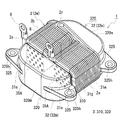
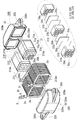
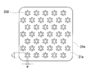
- FIG. 1 It is a schematic perspective view which shows the core piece of Embodiment 1, and a reactor provided with this core piece. It is a disassembled perspective view which shows the core piece of Embodiment 1, and a reactor provided with this core piece. It is explanatory drawing explaining an example (*) of the crossing groove
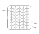
- FIG. It is explanatory drawing explaining an example (parallel line) of the crossing groove
- FIG. It is explanatory drawing explaining an example (vortex) of the crossing groove
- a core piece according to an aspect of the present invention is a core piece that constitutes a magnetic core disposed inside and outside a coil formed by winding a winding, and is orthogonal to the magnetic flux of the coil and includes a resin portion. Are joined to each other, and the end face is provided with an intersecting groove in which a plurality of grooves intersect without forming a loop.
- the intersecting groove refers to one continuous groove (hereinafter referred to as a first groove), a part of another groove (hereinafter referred to as a second groove) overlapping the first groove, and A groove that intersects so that both ends of the two grooves penetrate the first groove.
- the number of intersecting grooves in one intersecting groove two or more
- the shape of each groove which may be linear or curved
- the size of each groove can be selected as appropriate.
- the above-mentioned core piece is excellent in bondability because the bonding strength with the resin portion bonded to the end face is increased for the following reasons. Since a plurality of grooves are provided on the end face to which the resin portion of the core piece is bonded, the contact area between the core piece and the resin is larger than when there is no groove (such as Patent Document 1). When there are a plurality of grooves but do not intersect, for example, when linear grooves are arranged in parallel, there is a possibility that the resin portion bonded to the core piece peels off along the groove forming direction. That is, it can be said that the non-intersecting grooves are inferior in the bondability in a specific direction.
- the formation direction of each groove is different, and therefore the separation of the resin part along the formation direction of a certain groove can be prevented by another groove. Therefore, by providing a specific crossing groove, the bonding strength in any direction between the core piece and the resin portion bonded to the end of the core piece can be effectively increased.
- the metal particles are insulated from each other, so that eddy current can be reduced.
- the insulating material can be removed when the grooves are formed, and adjacent metal particles can be in a conductive state. That is, a groove having a loop can conduct along the loop, and an eddy current corresponding to the loop can be generated. Since the above core piece has a specific cross groove that does not have a loop on the end face perpendicular to the magnetic flux of the coil, when used for a magnetic component such as a reactor, eddy currents caused by the groove can be reduced. Contributes to the provision of lossy magnetic components.
- the core piece there may be mentioned a form that is a compacted body including metal particles and an insulating material interposed between the metal particles.
- the metal particles are insulated by an insulating material, eddy current can be reduced when used in magnetic parts such as a reactor.
- the insulating material in the groove portion can be removed when the groove is formed, the eddy current caused by the groove portion (conducting portion) can be reduced because it is a specific intersecting groove having no loop.
- the above-mentioned form is provided with a groove on its end face, it is the specific intersecting groove, so that it can reduce eddy currents caused by the groove when used in a magnetic part such as a reactor.
- the said form can utilize the resin part joined to the end surface provided with the said specific crossing groove as a gap.
- a gap is often provided between core pieces constituting a portion of the magnetic core disposed in the coil. Therefore, the gap member can be omitted when the core piece having the above-described configuration is arranged in the coil.
- the resin portion joined to the end face is firmly joined by the specific intersecting groove, it is possible to prevent a variation in gap length caused by peeling. Furthermore, when the resin portion bonded to the end surface also functions as a bonding material between adjacent core pieces, the integrity of the plurality of core pieces can be improved, and vibration and noise that may occur during use of a reactor or the like are reduced. Expected to be easy to reduce. Therefore, the above-mentioned form is 1. 1. The number of reactors and other parts can be reduced, contributing to improved manufacturability of reactors, etc. 2. Expected to contribute to the stability of the gap length of reactors, etc. It is also expected to contribute to the reduction of reactor vibration and noise.
- a reactor according to an aspect of the present invention is a magnetic including a plurality of core pieces including a coil formed by winding a winding and the core piece according to any one of (1) to (3) above.
- a core and a resin portion bonded to the end face of the core piece including the intersecting groove are provided.
- the reactor includes a coil formed by winding a winding, a magnetic core including a plurality of core pieces, and an end face orthogonal to the magnetic flux of the coil in at least one of the plurality of core pieces.
- the reactor includes a core piece including the above-described specific cross groove on the end surface to which the resin portion is bonded, the bonding strength between the core piece and the resin portion bonded to the end surface is high. Excellent bondability between core piece and resin part.
- channel provided in the end surface orthogonal to the magnetic flux of the coil in a core piece is a specific crossing groove
- the resin part interposed between the core pieces becomes a gap. Therefore, the said form can abbreviate
- a resin mold portion that covers an outer periphery of at least one of the plurality of core pieces is provided, and a resin portion bonded to the end surface is a part of the resin mold portion.
- a resin mold portion that covers an outer periphery of at least one of the plurality of core pieces is provided, and a resin portion bonded to the end surface is a part of the resin mold portion.
- the bonding strength between the core piece having the specific intersecting groove and the resin mold portion is increased, and the resin mold portion is firmly bonded.
- the said form can aim at the mechanical protection of a core piece, protection from an environment, etc.
- the covering core piece provided with a resin mold part is arrange
- the resin part joined to the end surface of a core piece can be simultaneously formed easily at the time of formation of a resin mold part, the said form can reduce the number of manufacturing processes and is excellent also in productivity.
- FIG. 2 shows a state in which a part of the middle resin mold part 310m of the inner core part 310 on one side (near side) is cut out and a part of the end face 31e of the core piece 31m is exposed.
- the reactor 1 is provided with the coil 2 formed by winding the coil
- the magnetic core 3 includes a plurality of columnar core pieces 31 m and 32 m, and the plurality of core pieces 31 m are disposed in the coil 2.
- the core piece 31m includes an end surface 31e disposed orthogonal to the axial direction of the coil 2 and a peripheral surface disposed parallel to the axial direction of the coil 2. When the coil 2 is excited, the magnetic flux of the coil 2 passes so as to be orthogonal to the end face 31e of the core piece 31m.
- a resin part here, part of the middle resin mold part 310m (FIG. 2) is joined to the end face 31e of the core piece 31m, and a cross groove 35A having a specific shape is provided. . This will be described in more detail below.
- the coil 2 includes a pair of cylindrical winding portions 2a and 2b formed by spirally winding a single continuous winding 2w as shown in FIGS. 1 and 2, and a winding 2w. And a connecting portion 2r that is formed from a part and connects the two winding portions 2a and 2b.
- Each winding part 2a, 2b is arranged in parallel (side by side) so that each axial direction is parallel.
- the winding 2w is a covered rectangular wire (so-called enameled wire) including a flat wire conductor (copper or the like) and an insulating coating (polyamideimide or the like) covering the outer periphery of the conductor, and the winding portion 2a. , 2b are edgewise coils.
- Both end portions 2e and 2e of the winding 2w are drawn out from the winding portions 2a and 2b in appropriate directions, and the terminal fittings 8 and 8 are connected to the conductor portions at the tips.
- the coil 2 is electrically connected to an external device (not shown) such as a power source via the terminal fitting 8.
- the magnetic core 3 is provided with the part arrange
- the magnetic core 3 of this example is composed of a core part in which a part for constructing a magnetic path is covered with a resin, specifically, two inner core parts 310 and 310 and two outer core parts 320 and 320.
- the inner core component 310 includes a middle main body portion 31 that constructs a magnetic path, and a middle resin mold portion 310m.
- the outer core component 320 includes a side main body portion 32 that constructs a magnetic path, and a side resin mold portion 320m.
- the magnetic core 3 has a pair of outer core parts 320 and 320 assembled so as to connect a pair of side-by-side inner core parts 310 and 310, and the middle main body parts 31 and 31 and the side main body parts 32 and 32 are annularly arranged. When the coil 2 is excited, a closed magnetic circuit is formed.
- the middle body portion 31 is composed of a plurality of core pieces 31m made of a soft magnetic material and a material having a relative permeability smaller than that of the core piece 31m (for example, gap materials 31g made of a nonmagnetic material such as alumina are alternately stacked to form a columnar shape (in this example, a rectangular parallelepiped shape with rounded corners).
- the core piece 31m and the gap material 31g are joined by an adhesive 370.
- a middle resin mold portion 310m is provided along the outer shape of the middle main body portion 31 so as to cover the entire outer periphery thereof.
- each end surface of the middle main body portion 31 (here, the end surface 31e of the core piece 31m) is a middle main body portion 31 to which the resin layer 372 is bonded.
- the core piece 31m and the core piece 32m of the side main body 32 adjacent to the core piece 31m function as a gap. That is, the reactor 1 of this example includes a plurality of gaps (gap material 31g and resin layer 372) made of different materials. Moreover, it can be said that the end surface 31e of the core piece 31m forms a gap.
- the number of core pieces 31m and gap material 31g can be changed as appropriate.
- the adhesive 370 and the resin layer 372 constitute a resin part 37 joined to the end face 31e orthogonal to the magnetic flux of the coil 2 in the core piece 31m.
- the side body part 32 is the core piece 32m comprised with the soft-magnetic material.
- the inner end surface 32e to which the pair of inner core components 310 and 310 are connected is a flat surface, and the upper surface and the lower surface have a dome shape whose cross-sectional area decreases from the inner end surface 32e outward ( Deformed trapezoidal shape).
- the inner end face 32e of the core piece 32m is also an end face orthogonal to the magnetic flux of the coil 2.
- Side resin mold part 320m is provided so that the outer periphery of side main-body part 32 may be covered along the external shape of side main-body part 32 except the area
- each of the core pieces 31m and 32m is a green compact formed substantially by metal particles and an insulating material interposed between the metal particles.
- the constituent resin of the middle resin mold part 310m and the side resin mold part 320m is polyphenylene sulfide (PPS) resin.
- PPS polyphenylene sulfide
- the above constituent resins include thermoplastic resins such as polytetrafluoroethylene (PTFE) resin, liquid crystal polymer (LCP), nylon 6, nylon 66, nylon 10T, nylon 9T, nylon 6T, and polybutylene terephthalate (PBT) resin. Can be mentioned.
- the green compact is typically formed from a raw material powder containing a metal powder such as iron or an iron alloy (Fe—Si alloy, Fe—Ni alloy, etc.) and a binder (resin etc.) or a lubricant as appropriate. Thereafter, it is obtained by performing a heat treatment for the purpose of removing distortions associated with molding.
- a coating powder obtained by subjecting a metal powder to an insulation treatment or a mixed powder obtained by mixing a metal powder and an insulating material as a raw material powder a compacted body in which an insulating material is interposed between metal particles can be obtained after molding.
- the green compact is composed of a coating powder in which metal particles are covered with an insulating coating.
- a die having a through hole and an upper punch and a lower punch that are inserted into the through hole and compress the raw material powder filled in the forming space including the inner peripheral surface of the die are used.
- the pressing surface formed by the upper punch and the lower punch in the green compact is typically a surface that is excellent in electrical insulation, with an insulating material interposed between metal particles.
- a pressing surface is a surface arranged perpendicular to the magnetic flux of the coil 2 in the core pieces 31m and 32m, the reactor 1 can reduce the eddy current caused by the coil 2.
- Each of the end faces 31e, 31e of each core piece 31m provided in the middle main body 31 disposed in the coil 2 is provided with a plurality of crossing grooves 35A.
- the intersecting groove 35A a plurality of grooves intersect without forming a loop.
- each of the intersecting grooves 35A has the same shape, and has a + shape in which two linear grooves having the same length are orthogonal to each other.
- the crossing angle of the grooves is not limited to orthogonal, but can be changed as appropriate, and can be an obtuse angle (acute angle). The same applies to the intersection grooves 35B to 35E described later.
- the plurality of cross grooves 35A shown in FIGS. 1 and 2 are aligned and arranged at a predetermined interval, and are uniformly formed over the entire end surface 31e of the core piece 31m. Specifically, an intersecting groove 35A that forms another row located above or below this row is located between adjacent intersecting grooves 35A and 35A that form a certain row. That is, the position of the cross groove 35A in each row is shifted in the left-right direction.
- the arrangement of the plurality of intersecting grooves 35A can be changed as appropriate.
- the shapes of other intersecting grooves will be described in detail with reference to FIGS.
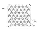
- the intersecting groove 35B shown in FIG. 3 has a * shape in which three linear grooves of the same length intersect at an equal intersecting angle (intersecting angle: 60 °). In this way, the number of grooves forming one intersecting groove can be three or more.
- a plurality of linear grooves intersect with one linear groove.
- a plurality of short grooves (here, grooves of the same length) intersect with a relatively long groove (intersection angle: 90 °).
- the intersecting groove 35C has a shape in which one groove forming the intersecting groove 35A is a continuous long groove. In this way, the number of grooves forming one intersecting groove can be increased, or the length of each groove can be varied.
- the plurality of intersecting grooves 35C are arranged in parallel so that the longitudinal direction of long grooves extends in the vertical direction, but are arranged in parallel so that the longitudinal direction of long grooves extend in the left-right direction. It can also be.
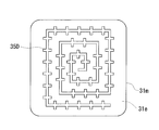
- the intersecting grooves 35D shown in FIG. 5 are continuously provided so that the linear grooves form a spiral, and a plurality of linear grooves intersect each side forming the spiral (intersection angle: 90 °).
- the lengths of the respective sides are gradually shortened from the periphery of the end surface 31e of the core piece 31m toward the center.
- intersects each said side is the same length, and is a short groove
- the intersecting groove 35D has a shape in which the length of the long groove of the intersecting groove 35C is appropriately changed and is arranged in a spiral shape. In this way, the number of grooves forming one cross groove can be increased, the length of each groove can be made different, and a continuous long groove can be provided.
- the spiral is a rectangular spiral, but it may be a circular spiral.
- a plurality of linear grooves (here, short grooves having the same length) intersect with a bowl-shaped groove (or C-shaped groove) (intersection angle: 90 °).
- the number of grooves forming one intersecting groove is increased, the length of each groove is different, a continuous long groove is provided, and a curved groove and a straight groove are further provided.
- the shape can be made different. In this example, a shape in which three short grooves intersect at equal intervals with respect to the bowl-shaped groove is shown, but the interval can be appropriately changed.
- the cross grooves 35A to 35E provided in the end surface 31e of the core piece 31m shown in FIGS. 1 to 6 are examples.
- the intersecting grooves can have various shapes such as ⁇ , x, ⁇ , *, and ⁇ .
- the plurality of intersecting grooves provided on one end surface 31e of the core piece 31m may include different shapes in addition to the same shape as shown in FIG.
- each groove (first groove, second groove, ...) constituting the intersecting groove 35A and the like can be appropriately selected.
- the width w of the groove is the length of the line that forms the end of the groove among the contour lines that form the outer shape of the groove when the end surface 31 e of the core piece 31 m is viewed in plan view.
- the length L is the length of a line that forms an intersection angle among the contour lines. It is considered that the greater the depth of each groove, or the larger the width w and length L of the groove, the greater the contact area with the resin part 37 and the higher the bonding strength with the resin part 37.
- the depth of each groove is preferably 10 ⁇ m or more and 200 ⁇ m or less, and more preferably 30 ⁇ m or more and 150 ⁇ m or less. In this example, the depth of each groove is 50 ⁇ m or more and 120 ⁇ m or less.
- the width w and length L of the groove may be selected depending on the size of the end face 31e of the core piece 31m, the shape of the groove, and the like.
- the ratio of the total area of the plurality of intersecting grooves 35A to the area of the end face 31e (hereinafter referred to as occupancy ratio) can be selected as appropriate. .
- occupancy ratio the higher the occupation ratio, the higher the bonding strength between the end face 31e and the resin portion 37, so 10% or more, 15% or more, and further 20% or more are considered preferable.
- the occupation ratio is preferably 80% or less, 70% or less, and more preferably 50% or less.
- the sizes (groove depth, width, length) of the plurality of intersecting grooves 35A existing on one end face 31e of the core piece 31m are the same, but the sizes are different.
- Crossing grooves can be provided. In this case, the cross grooves having the same shape and only different sizes may be used, and the cross grooves having different shapes and different sizes may be used.
- Method for forming cross grooves For example, laser processing such as laser light irradiation can be used for forming the cross grooves 35A to 35E. Irradiation conditions can be appropriately selected so that the size of the groove becomes a desired value. In this example, laser processing is used.
- Other groove forming methods include cutting with a cutting tool.
- the insulating material interposed between the metal particles can be removed. Therefore, when a groove is formed on the above-described pressing surface, the groove portion can be conducted.
- the pressing surface is a surface arranged so as to be orthogonal to the magnetic flux of the coil 2 in the core piece 31m, and this surface (the end surface 31e in this case) is provided with an intersecting groove 35A or the like. Even if the magnetic flux of the coil 2 passes through 31e, it is possible to prevent an eddy current from flowing in a loop along the intersecting groove 35A or the like.
- a plurality of cross grooves 35A are provided on each of the end faces 31e and 31e of the core piece 31m.
- the end face 31e of the core piece 31m having the intersecting groove 35A and the gap material 31g are joined together by an adhesive 370 to form the middle main body 31.
- a sheet material is shown as the adhesive 370, but the adhesive 370 may be applied to one surface of the end surface 31e or the gap material 31g.
- the prepared middle main body parts 31 and 31 and separately prepared side main body parts 32 and 32 are used as cores, and the inner core parts 310 and 310 and the outer core parts 320 and 320 are manufactured by injection molding such as insert molding.
- a part of the middle resin mold part 310m (resin layer 372) is provided on each of the end faces 31e, 31e of the core pieces 31m, 31m located at each end of the middle main body part 31, respectively.
- an adhesive 370 is bonded to both end faces 31e, 31e of the core piece 31m located in the middle of the middle main body 31.
- the inner core parts 310 and 310, the separately prepared coil 2 and the outer core parts 320 and 320 are assembled to form the annular magnetic core 3, and the coil 2 is supported by the magnetic core 3.
- the end surfaces 310e, 310e of the inner core components 310, 310 and the inner end surface of the outer core component 320 may be joined with an adhesive (not shown).
- the reactor 1 is obtained by the above process.
- the core piece 31m of the first embodiment is provided with a plurality of specific-shaped intersecting grooves 35A (35B to 35E, etc.) on the end surface 31e, so that when the resin portion 37 is bonded to the end surface 31e, the core piece 31m can be firmly bonded. Further, when the end face 31e of the core piece 31m is arranged so as to be orthogonal to the magnetic flux of the coil 2, the generation of eddy current can be reduced.
- a plurality of cross grooves 35A (35B to 35E, etc.) having a specific shape are provided on an end surface 31e orthogonal to the magnetic flux of the coil 2.
- the resin portion 37 is firmly joined to the both end surfaces 31e and 31e of the core piece 31m with a plurality of cross grooves 35A and the like, the integration of the middle main body portion 31 is sufficiently enhanced. Therefore, it is expected that vibration and noise can be easily reduced during use.
- the configuration in which the resin portion 37 is configured by the adhesive 370 and a part of the middle resin mold portion 310m (resin layer 372) has been described.
- the gap material 31g and the adhesive 370 may be omitted, and the resin part may be configured by a part of the resin mold part 310m. That is, the gap between the core pieces 31m and 31m and the gap between the core pieces 31m and 32m can all be constituted by a part of the resin mold portion 310m.
- the core pieces 31m provided with the intersecting grooves 35A and the like are arranged at predetermined intervals on the mold, and the resin is placed between the adjacent core pieces 31m and 31m.
- the resin gap can be easily formed.
- both end faces 31e and 31e of the core piece 31m are provided with cross grooves 35A and the like because the resin portion interposed between the core pieces 31m and 31m can be firmly joined.
- the resin portion interposed between the core pieces 31m and 31m also functions as an adhesive (joining material) that joins the core pieces 31m and 31m in addition to the gap described above. Since the core pieces 31m and 31m are firmly joined to each other by the resin mold part 310m, it is expected that the integration of the middle main body part 31 can be sufficiently enhanced and vibration and noise can be easily reduced when the reactor is used.
- the covering region of the side resin mold part 320m can be changed, and the entire outer periphery of the core piece 32m including the inner end face 32e can be covered with the resin mold part 320m.
- a flat resin layer that is a part of the resin mold portion 320m and covers the inner end surface 32e of the core piece 32m is a resin portion joined to the inner end surface 32e orthogonal to the magnetic flux of the coil 2.
- both of the core pieces 31m and 32m provided in the magnetic core 3 are provided with a resin portion on end faces (31e and 32e) orthogonal to the magnetic flux of the coil 2.
- the form in which the middle main body portion 31 in which the plurality of core pieces 31m and the gap material 31g are stacked is integrally covered with the middle resin mold portion 310m has been described.
- it can be set as the form provided with two or more covering core pieces which formed the resin mold part for every core piece 31m.
- Each of the coated core pieces includes cross grooves 35A and the like on both end faces 31e and 31e of the core piece 31m, and a part of the resin mold portion (a flat resin layer) is joined.
- a part of the resin mold part joined to one end face 31e of the core piece 31m of each coated core piece, that is, two resin layers are interposed between adjacent coated core pieces. It becomes a gap. Therefore, in this embodiment, the gap material 31g can be omitted, and the number of parts can be reduced.
- the magnetic core 3 includes four core components (the inner core components 310 and 310 and the outer core components 320 and 320) has been described.
- one middle main body portion 31 and one side main body portion 32 are assembled in an L shape and are provided with a set of L-shaped core parts integrally held in the resin mold portion, two middle main body portions 31, 31 and the one side main-body part 32 are assembled
- the reactor 1 shown in FIG. 1 includes the following engaging portion, a mounting portion 325, and a partition portion configured by a middle resin mold portion 310m and a side resin mold portion 320m. At least one of the engagement portion, the attachment portion 325, and the partition portion can be omitted.
- the middle resin mold part 310m is provided with the area
- the side resin mold part 320m includes two cylindrical parts provided so as to protrude from the inner end face of the outer core part 320. The thin region and the cylindrical portion function as an engaging portion. -Mounting portion 325 for attaching the reactor 1 to the installation target (FIGS. 1 and 2) In this example, the side resin mold part 320m has a protruding piece protruding outward.
- a bolt hole 325 h is provided in the projecting piece, and this projecting piece is used for the attachment portion 325.
- -Partition part interposed between the winding parts 2a, 2b In this example, the side resin mold part 320m protrudes from the inner end surface of the outer core part 320, and a plate piece provided between the two cylinder parts. Prepare. This board piece functions as a partition part, and ensures insulation of both winding parts 2a and 2b.
- the reactor according to the first embodiment and the modification can include the following members. At least one of these members can be omitted.
- a sensor that measures the physical quantity of the reactor 1 such as a temperature sensor, a current sensor, a voltage sensor, or a magnetic flux sensor can be provided. .. Heat radiation plate A heat radiation plate (not shown) can be provided at any location on the outer peripheral surface of the coil 2. For example, if the installation surface (here, the lower surface) of the coil 2 is provided with a heat dissipation plate, the heat of the coil 2 can be well transmitted to the installation object such as the converter case through the heat dissipation plate, thereby improving the heat dissipation.
- a material having excellent thermal conductivity such as a metal such as aluminum or an alloy thereof or a non-metal such as alumina can be used.
- the heat radiating plate can be fixed to the assembly of the coil 2 and the magnetic core 3 by, for example, a bonding layer described later. ..Junction Layer Of the installation surface (here, the lower surface) of the reactor 1, a bonding layer (not shown) can be provided on at least the installation surface (here, the lower surface) of the coil 2.
- the coil 2 can be firmly fixed to the heat sink when the installation target or the above heat sink is provided, the movement of the coil 2 is restricted, the heat dissipation is improved, the installation target or the heat sink Fixing stability can be achieved.
- Constituent material of the bonding layer contains an insulating resin, particularly ceramic filler, and has excellent heat dissipation (for example, thermal conductivity is 0.1 W / m ⁇ K or more, further 1 W / m ⁇ K or more, especially 2 W / M ⁇ K or more).
- the resin include thermosetting resins such as epoxy resin, silicone resin, and unsaturated polyester, and thermoplastic resins such as PPS resin and LCP.
- this invention is not limited to these illustrations, is shown by the claim, and it is intended that all the changes within the meaning and range equivalent to the claim are included.
- it can be set as the reactor provided with a coil with only one winding part.
- the core piece provided with the specific crossing groove described above can be used as a component of the magnetic core of the magnetic component other than the reactor.
- the core piece of the present invention can be suitably used for components of magnetic parts such as a reactor, a transformer, a motor, and a choke coil.
- the reactor of the present invention includes various on-vehicle converters (typically DC-DC converters) mounted on vehicles such as hybrid vehicles, plug-in hybrid vehicles, electric vehicles, and fuel cell vehicles, and converters for air conditioners. It can utilize suitably for the component of a converter and a power converter.
Abstract
L'invention concerne une pièce de noyau et un réacteur ayant une excellente adhérence à une partie en résine et grâce à laquelle il est possible d'atténuer une génération de courant excessive. La pièce de noyau constitue un noyau magnétique disposé à l'intérieur et à l'extérieur d'une bobine formée par bobinage d'un enroulement, la pièce de noyau étant pourvue d'une surface de bord perpendiculaire au flux magnétique de la bobine et comportant une partie en résine liée à cette dernière, la surface de bord étant pourvue de rainures qui se croisent et dont plusieurs se croisent sans former de boucle. Ladite pièce de noyau est par exemple un corps moulé par moulage de poudres, comportant des particules métalliques et un matériau isolant intercalé entre les particules métalliques. La présente pièce de noyau constitue par exemple une partie du noyau magnétique disposé à l'intérieur de la bobine.
Priority Applications (3)
| Application Number | Priority Date | Filing Date | Title |
|---|---|---|---|
| CN201580019214.6A CN106170838B (zh) | 2014-04-25 | 2015-04-14 | 芯片及电抗器 |
| DE112015001998.7T DE112015001998T5 (de) | 2014-04-25 | 2015-04-14 | Kernstück und Drossel |
| US15/304,353 US20170040100A1 (en) | 2014-04-25 | 2015-04-14 | Core piece and reactor |
Applications Claiming Priority (2)
| Application Number | Priority Date | Filing Date | Title |
|---|---|---|---|
| JP2014-092149 | 2014-04-25 | ||
| JP2014092149A JP6265031B2 (ja) | 2014-04-25 | 2014-04-25 | コア片及びリアクトル |
Publications (1)
| Publication Number | Publication Date |
|---|---|
| WO2015163190A1 true WO2015163190A1 (fr) | 2015-10-29 |
Family
ID=54332357
Family Applications (1)
| Application Number | Title | Priority Date | Filing Date |
|---|---|---|---|
| PCT/JP2015/061452 WO2015163190A1 (fr) | 2014-04-25 | 2015-04-14 | Pièce de noyau et réacteur |
Country Status (5)
| Country | Link |
|---|---|
| US (1) | US20170040100A1 (fr) |
| JP (1) | JP6265031B2 (fr) |
| CN (1) | CN106170838B (fr) |
| DE (1) | DE112015001998T5 (fr) |
| WO (1) | WO2015163190A1 (fr) |
Families Citing this family (3)
| Publication number | Priority date | Publication date | Assignee | Title |
|---|---|---|---|---|
| JP6465459B2 (ja) * | 2015-12-24 | 2019-02-06 | 株式会社オートネットワーク技術研究所 | 複合材料成形体、リアクトル、及び複合材料成形体の製造方法 |
| JP6808177B2 (ja) * | 2017-11-21 | 2021-01-06 | 株式会社オートネットワーク技術研究所 | リアクトル |
| JP7015453B2 (ja) * | 2018-08-09 | 2022-02-03 | 株式会社オートネットワーク技術研究所 | リアクトル |
Citations (4)
| Publication number | Priority date | Publication date | Assignee | Title |
|---|---|---|---|---|
| JP2003203813A (ja) * | 2001-08-29 | 2003-07-18 | Matsushita Electric Ind Co Ltd | 磁性素子およびその製造方法、並びにそれを備えた電源モジュール |
| JP2007305717A (ja) * | 2006-05-10 | 2007-11-22 | Matsushita Electric Ind Co Ltd | インダクタンス部品とその製造方法 |
| JP2008010695A (ja) * | 2006-06-30 | 2008-01-17 | Matsushita Electric Ind Co Ltd | インダクタンス部品 |
| JP2013211371A (ja) * | 2012-03-30 | 2013-10-10 | Toyota Motor Corp | リアクトル |
Family Cites Families (6)
| Publication number | Priority date | Publication date | Assignee | Title |
|---|---|---|---|---|
| CN1090916C (zh) * | 1999-12-24 | 2002-09-18 | 中国人民解放军军事医学科学院卫生学环境医学研究所 | 一种预防高原病的口服液及其制备方法 |
| US6768409B2 (en) * | 2001-08-29 | 2004-07-27 | Matsushita Electric Industrial Co., Ltd. | Magnetic device, method for manufacturing the same, and power supply module equipped with the same |
| JP5082271B2 (ja) * | 2006-03-24 | 2012-11-28 | パナソニック株式会社 | チップコイルとその製造方法 |
| JP2012169425A (ja) * | 2011-02-14 | 2012-09-06 | Sumitomo Electric Ind Ltd | リアクトル |
| JP2012209333A (ja) * | 2011-03-29 | 2012-10-25 | Sumitomo Electric Ind Ltd | リアクトル、およびリアクトルの製造方法 |
| JP6197736B2 (ja) * | 2014-04-25 | 2017-09-20 | 住友電装株式会社 | コア片及びリアクトル |
-
2014
- 2014-04-25 JP JP2014092149A patent/JP6265031B2/ja active Active
-
2015
- 2015-04-14 WO PCT/JP2015/061452 patent/WO2015163190A1/fr active Application Filing
- 2015-04-14 CN CN201580019214.6A patent/CN106170838B/zh not_active Expired - Fee Related
- 2015-04-14 US US15/304,353 patent/US20170040100A1/en not_active Abandoned
- 2015-04-14 DE DE112015001998.7T patent/DE112015001998T5/de not_active Ceased
Patent Citations (4)
| Publication number | Priority date | Publication date | Assignee | Title |
|---|---|---|---|---|
| JP2003203813A (ja) * | 2001-08-29 | 2003-07-18 | Matsushita Electric Ind Co Ltd | 磁性素子およびその製造方法、並びにそれを備えた電源モジュール |
| JP2007305717A (ja) * | 2006-05-10 | 2007-11-22 | Matsushita Electric Ind Co Ltd | インダクタンス部品とその製造方法 |
| JP2008010695A (ja) * | 2006-06-30 | 2008-01-17 | Matsushita Electric Ind Co Ltd | インダクタンス部品 |
| JP2013211371A (ja) * | 2012-03-30 | 2013-10-10 | Toyota Motor Corp | リアクトル |
Also Published As
| Publication number | Publication date |
|---|---|
| US20170040100A1 (en) | 2017-02-09 |
| CN106170838A (zh) | 2016-11-30 |
| JP2015211142A (ja) | 2015-11-24 |
| DE112015001998T5 (de) | 2017-01-12 |
| JP6265031B2 (ja) | 2018-01-24 |
| CN106170838B (zh) | 2018-05-11 |
Similar Documents
| Publication | Publication Date | Title |
|---|---|---|
| US10283255B2 (en) | Reactor | |
| WO2011089941A1 (fr) | Bobine de réactance | |
| US8686820B2 (en) | Reactor | |
| CN107408450B (zh) | 电抗器 | |
| JP6197736B2 (ja) | コア片及びリアクトル | |
| WO2016129487A1 (fr) | Pièce de noyau de réactance, procédé de fabrication de pièce de noyau de réactance, et réactance | |
| JP6288510B2 (ja) | リアクトル | |
| JP2012209333A (ja) | リアクトル、およびリアクトルの製造方法 | |
| WO2016143730A1 (fr) | Réacteur | |
| JP2016066686A (ja) | リアクトル | |
| JP6265031B2 (ja) | コア片及びリアクトル | |
| JP2018074127A (ja) | コイル構造体 | |
| WO2016143729A1 (fr) | Réacteur | |
| JP2013179186A (ja) | リアクトル、リアクトル用部品、コンバータ、及び電力変換装置 | |
| JP2012119454A (ja) | リアクトル | |
| JP2012209327A (ja) | リアクトル | |
| WO2016002783A1 (fr) | Pièce de noyau et réacteur | |
| JP2015159144A (ja) | インダクタ | |
| US11501912B2 (en) | Reactor | |
| CN109791833B (zh) | 线圈、电抗器及线圈的设计方法 | |
| CN112805797B (zh) | 电抗器 | |
| JP2018074128A (ja) | コイル構造体 | |
| US11908613B2 (en) | Reactor | |
| JP6598084B2 (ja) | コイル、及びリアクトル | |
| WO2016072245A1 (fr) | Réacteur |
Legal Events
| Date | Code | Title | Description |
|---|---|---|---|
| 121 | Ep: the epo has been informed by wipo that ep was designated in this application |
Ref document number: 15783072 Country of ref document: EP Kind code of ref document: A1 |
|
| WWE | Wipo information: entry into national phase |
Ref document number: 15304353 Country of ref document: US |
|
| WWE | Wipo information: entry into national phase |
Ref document number: 112015001998 Country of ref document: DE |
|
| 122 | Ep: pct application non-entry in european phase |
Ref document number: 15783072 Country of ref document: EP Kind code of ref document: A1 |