WO2015163097A1 - 筐体の冷却液ドレイン構造および蓄電装置並びに建設機械 - Google Patents
筐体の冷却液ドレイン構造および蓄電装置並びに建設機械 Download PDFInfo
- Publication number
- WO2015163097A1 WO2015163097A1 PCT/JP2015/060025 JP2015060025W WO2015163097A1 WO 2015163097 A1 WO2015163097 A1 WO 2015163097A1 JP 2015060025 W JP2015060025 W JP 2015060025W WO 2015163097 A1 WO2015163097 A1 WO 2015163097A1
- Authority
- WO
- WIPO (PCT)
- Prior art keywords
- flow path
- drain
- cooling
- plug
- partition wall
- Prior art date
- Legal status (The legal status is an assumption and is not a legal conclusion. Google has not performed a legal analysis and makes no representation as to the accuracy of the status listed.)
- Ceased
Links
Images



Classifications
-
- H—ELECTRICITY
- H05—ELECTRIC TECHNIQUES NOT OTHERWISE PROVIDED FOR
- H05K—PRINTED CIRCUITS; CASINGS OR CONSTRUCTIONAL DETAILS OF ELECTRIC APPARATUS; MANUFACTURE OF ASSEMBLAGES OF ELECTRICAL COMPONENTS
- H05K7/00—Constructional details common to different types of electric apparatus
- H05K7/20—Modifications to facilitate cooling, ventilating, or heating
- H05K7/20218—Modifications to facilitate cooling, ventilating, or heating using a liquid coolant without phase change in electronic enclosures
- H05K7/20272—Accessories for moving fluid, for expanding fluid, for connecting fluid conduits, for distributing fluid, for removing gas or for preventing leakage, e.g. pumps, tanks or manifolds
-
- H—ELECTRICITY
- H01—ELECTRIC ELEMENTS
- H01G—CAPACITORS; CAPACITORS, RECTIFIERS, DETECTORS, SWITCHING DEVICES, LIGHT-SENSITIVE OR TEMPERATURE-SENSITIVE DEVICES OF THE ELECTROLYTIC TYPE
- H01G11/00—Hybrid capacitors, i.e. capacitors having different positive and negative electrodes; Electric double-layer [EDL] capacitors; Processes for the manufacture thereof or of parts thereof
- H01G11/10—Multiple hybrid or EDL capacitors, e.g. arrays or modules
-
- H—ELECTRICITY
- H01—ELECTRIC ELEMENTS
- H01G—CAPACITORS; CAPACITORS, RECTIFIERS, DETECTORS, SWITCHING DEVICES, LIGHT-SENSITIVE OR TEMPERATURE-SENSITIVE DEVICES OF THE ELECTROLYTIC TYPE
- H01G11/00—Hybrid capacitors, i.e. capacitors having different positive and negative electrodes; Electric double-layer [EDL] capacitors; Processes for the manufacture thereof or of parts thereof
- H01G11/14—Arrangements or processes for adjusting or protecting hybrid or EDL capacitors
- H01G11/18—Arrangements or processes for adjusting or protecting hybrid or EDL capacitors against thermal overloads, e.g. heating, cooling or ventilating
-
- H—ELECTRICITY
- H01—ELECTRIC ELEMENTS
- H01G—CAPACITORS; CAPACITORS, RECTIFIERS, DETECTORS, SWITCHING DEVICES, LIGHT-SENSITIVE OR TEMPERATURE-SENSITIVE DEVICES OF THE ELECTROLYTIC TYPE
- H01G2/00—Details of capacitors not covered by a single one of groups H01G4/00-H01G11/00
- H01G2/08—Cooling arrangements; Heating arrangements; Ventilating arrangements
-
- H—ELECTRICITY
- H05—ELECTRIC TECHNIQUES NOT OTHERWISE PROVIDED FOR
- H05K—PRINTED CIRCUITS; CASINGS OR CONSTRUCTIONAL DETAILS OF ELECTRIC APPARATUS; MANUFACTURE OF ASSEMBLAGES OF ELECTRICAL COMPONENTS
- H05K7/00—Constructional details common to different types of electric apparatus
- H05K7/20—Modifications to facilitate cooling, ventilating, or heating
- H05K7/2089—Modifications to facilitate cooling, ventilating, or heating for power electronics, e.g. for inverters for controlling motor
- H05K7/20927—Liquid coolant without phase change
-
- E—FIXED CONSTRUCTIONS
- E02—HYDRAULIC ENGINEERING; FOUNDATIONS; SOIL SHIFTING
- E02F—DREDGING; SOIL-SHIFTING
- E02F9/00—Component parts of dredgers or soil-shifting machines, not restricted to one of the kinds covered by groups E02F3/00 - E02F7/00
- E02F9/08—Superstructures; Supports for superstructures
- E02F9/0858—Arrangement of component parts installed on superstructures not otherwise provided for, e.g. electric components, fenders, air-conditioning units
-
- E—FIXED CONSTRUCTIONS
- E02—HYDRAULIC ENGINEERING; FOUNDATIONS; SOIL SHIFTING
- E02F—DREDGING; SOIL-SHIFTING
- E02F9/00—Component parts of dredgers or soil-shifting machines, not restricted to one of the kinds covered by groups E02F3/00 - E02F7/00
- E02F9/20—Drives; Control devices
- E02F9/2058—Electric or electro-mechanical or mechanical control devices of vehicle sub-units
- E02F9/2062—Control of propulsion units
- E02F9/2075—Control of propulsion units of the hybrid type
-
- Y—GENERAL TAGGING OF NEW TECHNOLOGICAL DEVELOPMENTS; GENERAL TAGGING OF CROSS-SECTIONAL TECHNOLOGIES SPANNING OVER SEVERAL SECTIONS OF THE IPC; TECHNICAL SUBJECTS COVERED BY FORMER USPC CROSS-REFERENCE ART COLLECTIONS [XRACs] AND DIGESTS
- Y02—TECHNOLOGIES OR APPLICATIONS FOR MITIGATION OR ADAPTATION AGAINST CLIMATE CHANGE
- Y02E—REDUCTION OF GREENHOUSE GAS [GHG] EMISSIONS, RELATED TO ENERGY GENERATION, TRANSMISSION OR DISTRIBUTION
- Y02E60/00—Enabling technologies; Technologies with a potential or indirect contribution to GHG emissions mitigation
- Y02E60/10—Energy storage using batteries
-
- Y—GENERAL TAGGING OF NEW TECHNOLOGICAL DEVELOPMENTS; GENERAL TAGGING OF CROSS-SECTIONAL TECHNOLOGIES SPANNING OVER SEVERAL SECTIONS OF THE IPC; TECHNICAL SUBJECTS COVERED BY FORMER USPC CROSS-REFERENCE ART COLLECTIONS [XRACs] AND DIGESTS
- Y02—TECHNOLOGIES OR APPLICATIONS FOR MITIGATION OR ADAPTATION AGAINST CLIMATE CHANGE
- Y02E—REDUCTION OF GREENHOUSE GAS [GHG] EMISSIONS, RELATED TO ENERGY GENERATION, TRANSMISSION OR DISTRIBUTION
- Y02E60/00—Enabling technologies; Technologies with a potential or indirect contribution to GHG emissions mitigation
- Y02E60/13—Energy storage using capacitors
Definitions
- the present invention relates to a coolant drain structure of a casing, a power storage device, and a construction machine.
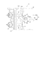
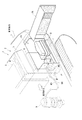
- FIG. 8 shows the arrangement of the hybrid device used in the hydraulic excavator of Patent Document 1.
- the axial direction of the crankshaft (not shown) is parallel to the vehicle width direction (horizontal direction orthogonal to the vehicle longitudinal direction).
- the engine 3 is mounted so that A cooling fan 4 that draws cooling air from the outside into the engine room 2A in order toward the outside on one side in the vehicle width direction with respect to the engine 3, an engine radiator 5 that is cooled by the drawn cooling air,
- the hybrid radiator 6 and a plurality of hybrid devices are arranged.
- the hybrid device is arranged on the other side of the engine 3 and is driven by the engine 3, a power generation motor (not shown), a capacitor 7 that stores power generated by the power generation motor, power storage in the capacitor 7, and capacitor 7
- the inverter 8 that controls the supply from the motor and the electric swing motor 9 that is driven by the electric power from the capacitor 7 are provided.
- the capacitor 7 and the inverter 8 are unitized together with the terminal box, and are disposed at a position accessible by opening the side cover 2B that can be freely opened and closed.
- the capacitor 7, the inverter 8, and the electric swing motor 9 are cooled by a dedicated cooling water circuit including the hybrid radiator 6.
- the cooling water cooled by the hybrid radiator 6 is first sent to the capacitor 7 through the pipe W1 by the cooling water pump P.
- the cooling water that has cooled the capacitor 7 is sent to the inverter 8 mounted on the upper portion of the capacitor 7 through the pipe W2.
- the cooling water that has cooled the inverter 8 is sent to the electric swing motor 9 through the pipe W3.
- the cooling water that has cooled the electric swing motor 9 is returned to the hybrid radiator 6 through the pipe W4.
- a cooling channel is formed at the bottom of the casing.
- the cooling flow path is formed in a U shape in plan view so that the inlet In and the outlet Out of the cooling water are provided on the same side surface of the casing. That is, the cooling water flowing in from the inlet In on one end side of the U-shaped cooling flow path is folded back 180 degrees and flows out of the outlet Out. Therefore, a partition wall that partitions the cooling flow path into an upstream flow path section and a downstream flow path section is provided at the bottom of the housing, with the folded portion in the flow direction as a boundary.
- drain holes for extracting cooling water from the cooling flow path are provided in each of the upstream flow path portion and the downstream flow path portion. Therefore, even if the vehicle stops in a slightly inclined posture, the cooling water does not remain in each flow path portion, and can be surely drained through the drain hole of any flow path portion.
- the drain holes are provided at positions close to each other.
- the drain holes due to restrictions on the size of the housing of the capacitor 7 and the like, it is possible to arrange the drain holes having a large hole diameter in two places. There is a problem that you can not.
- drain holes are provided in two places itself takes time to attach and detach the drain plug for sealing them, and a solution to this is desired. That is, when removing the drain plug from the second drain hole, the cooling water from the first drain hole is applied to the operator, and workability is poor.
- An object of the present invention is to provide a coolant drain structure of a casing, a power storage device, and a construction machine that can improve maintainability.
- the cooling liquid drain structure of the casing of the present invention is a cooling liquid drain structure of the casing that discharges the cooling liquid from the cooling flow path provided at the bottom of the casing in which the object to be cooled is accommodated.
- a partition wall that partitions the cooling channel into at least a pair of a first channel unit and a second channel unit, and both the first channel unit and the second channel unit across the partition wall
- a drain plug that is detachably attached to the drain hole and seals the drain hole, and a portion of the drain plug that is exposed in the cooling channel is provided with the drain hole. The flow between the flow paths at the communication portion with the first flow path section and the second flow path section is suppressed.
- the first flow path part and the second flow path part need only have one drain hole straddling them, and only one drain plug can be attached to and detached from the drain hole.
- the drain plug can be attached and detached easily. Further, since there is one drain hole, the drain hole can be reliably provided even if the hole diameter of the drain hole is increased. As described above, maintainability can be improved.
- a portion corresponding to the drain hole of the partition wall is provided with a guide portion whose thickness decreases toward the cooling liquid discharge direction.
- a portion corresponding to the drain hole of the partition wall is configured by a bypass plug that is a separate member different from other portions, and the partition wall includes the bypass It is preferable that the notch part to which a plug is attached is provided.
- the cooling flow path is a cooling liquid divided by a groove-like portion provided at the bottom of the housing and a flow path cover covering the groove-like portion. It is preferable that the end of the bypass plug opposite to the drain hole is formed as a circulation space and is locked by the flow path cover.
- the bypass plug is preferably made of an elastic material.
- the power storage device includes a housing in which any one of the coolant drain structures described above is employed.
- the construction machine according to the present invention includes the power storage device.
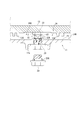
- FIG. 3 is a cross-sectional view showing the main part of the coolant drain structure, as viewed from the arrow III-III in FIG. 2.
- FIG. 4 is a cross-sectional view showing the main part of the coolant drain structure, as viewed from arrows IV-IV in FIG. 2.
- the whole perspective view which shows the bypass plug used for the drain structure for cooling.
- Sectional drawing which shows the modification of this invention.
- Sectional drawing which shows another modification of this invention.
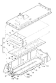
- FIG. 1 is an exploded perspective view showing a capacitor as a power storage device in which the cooling liquid drain structure of the housing of the present embodiment is adopted.
- the function and use of the capacitor 10 are the same as those of the capacitor 7 described with reference to FIG. 8, and are mounted on a hybrid hydraulic excavator 1 as a construction machine.
- the capacitor 10 is made of aluminum die casting and has a bottomed box-like casing 11, an aluminum die-cast casing cover 12 that closes an opening above the casing 11, and the bottom of the casing 11.
- a flow path cover 13 fixed by a plurality of bolts 10 ⁇ / b> A (see FIG.
- the capacitor 10 is provided with a number of electrical wirings and the like for electrically connecting the capacitor assembly 14 and the outside, but these are not shown in FIG.
- the flow path cover 13 is made of an extruded aluminum material, and has a plurality of fins 13A along the extrusion direction on the lower surface thereof.
- the capacitor assembly 14 has a structure in which a plurality of capacitor units 15 are arranged in parallel along the longitudinal direction of the casing 11 having a substantially rectangular parallelepiped shape.
- Each capacitor unit 15 further has a structure in which a plurality of capacitor modules 16 are held by upper and lower holding members 17 and 18 and an aluminum heat sink 19.
- the heat generated in the capacitor assembly 14 is transmitted to the flow path cover 13 through the heat sink 19 and is radiated to the cooling water as the cooling liquid.
- Such a capacitor assembly 14 itself is not directly related to the present invention, and further description thereof is omitted.
- a configuration related to the cooling drain structure provided in the housing 11 will be described in detail.
- the bottom portion 11A of the housing 11 has an annular outer partition wall 21 along the four peripheral edges 11B, 11C, 11D, and 11E of the bottom portion 11A, and one short side side edge 11B of the outer partition wall 21.
- An inner partition wall 22 is provided as a partition wall extending from the approximate center of the extending portion toward the other short side edge 11D.
- the end on the short side side edge 11 ⁇ / b> B side is continuous with the outer partition wall 21, and the end on the short side side edge 11 ⁇ / b> D side is not continuous with the outer partition wall 21.
- the outer partition wall 21 and the inner partition wall 22 are provided so as to protrude from the bottom portion 11 ⁇ / b> A to a predetermined height, and a groove portion 23 is formed by a valley portion partitioned by the outer partition wall 21 and the inner partition wall 22. Yes.
- the flow path cover 13 is bolted to the upper end surface which is a protrusion end surface of the outer side partition wall 21 and the inner side partition wall 22 via a liquid seal, and the said groove-shaped part 23 is covered.
- the groove-like portion 23 and the flow path cover 13 covering the groove-like portion 23 form a circulation space through which cooling water flows, that is, a cooling flow path 24.
- the outer partition wall 21 defines the outer edge of the cooling flow path 24, the outer partition wall 21 has a substantially rectangular ring shape that is close to the shape of the capacitor assembly 14 to be cooled in plan view.
- Such a cooling flow path 24 is formed in a U shape in a plan view by the upstream first flow path section 24A and the downstream second flow path section 24B partitioned by the central inner partition wall 22. ing.
- the flow path widths of the first flow path part 24A and the second flow path part 24B are substantially equal, along the end part on the short side side edge 11D side of the inner partition wall 22 and the short side side edge 11D of the outer partition wall 21. The distance to the part is about this channel width.
- the cooling flow path 24 includes an inlet section 25 (see FIG. 2) through which cooling water flows from the base end side of the first flow path section 24A, and an outlet section from which cooling water flows out from the terminal end side of the second flow path section 24B. 26 (see FIG. 2). Both the inlet portion 25 and the outlet portion 26 open to the side wall portion 11F on the short side edge 11B side, and pipe joints 27 are respectively provided in these opening portions, and each pipe joint 27 is shown in FIG. Pipes W1 and W2 are connected.
- FIG. 2 is a plan view showing the main part of the coolant drain structure.
- FIG. 3 is a cross-sectional view showing the main part of the coolant drain structure, and is a cross-sectional view seen from the arrow III-III in FIG. 2, and
- FIG. 4 is a cross-sectional view seen from the arrow IV-IV in FIG.
- the first flow path portion 24 ⁇ / b> A and the second flow path are located at a position closer to the cooling water inflow / outflow side with the inner partition wall 22 as a boundary.
- One drain hole 28 for discharging is provided in both of the portions 24B. Accordingly, the cooling water can be discharged from both the first flow path portion 24A and the second flow path portion 24B from the drain hole 28 as indicated by an arrow in FIG.
- the drain hole 28 is provided with a female screw portion (not shown) at least partially, and a bolt-shaped drain plug 29 is screwed from below to seal the drain hole 28.
- a bolt-shaped drain plug 29 is screwed from below to seal the drain hole 28.
- an O-ring 29A is inserted through the drain plug 29, and a contact surface with which the O-ring 29A contacts in the circumferential direction is provided below the drain hole 28.
- a recess 11G into which the head of the screwed drain plug 29 is inserted is provided on the lower surface of the housing 11 to suppress the head of the drain plug 29 from colliding with other parts when the capacitor 10 is mounted.
- the drain plug 29 is not directly loaded. A space for inserting a tool to be locked to the head is secured between the periphery of the head of the drain plug 29 and the recess 11G.
- a notch 22 ⁇ / b> A is provided at a position corresponding to the drain hole 28 so as to divide the inner partition wall 22. Accordingly, there is no aluminum die cast part above the drain hole 28.
- the notch 22A is composed of an upper wide portion 22B and a lower narrow portion 22C, and the bottom surface of the wide portion 22B is a mounting seat 22D.
- the opposing inner wall surfaces 22E of the wide portion 22B are formed as vertical surfaces parallel to each other. That is, the inner wall surfaces 22 ⁇ / b> E and 22 ⁇ / b> E are provided with a space along the extending direction of the inner partition wall 22.
- the narrow portion 22 ⁇ / b> C is provided as a pilot hole for the female thread portion of the drain hole 28.
- the bypass plug 30 is a part of the inner partition wall 22, and the entire inner partition wall 22 is formed including the bypass plug 30.
- FIG. 5 is an overall perspective view showing the bypass plug 30. 2 to 5, the bypass plug 30 is entirely formed of an elastic material such as synthetic rubber, and is fitted in the wide portion 22B of the notch 22A, and the lower surface of the bypass plug 30 is seated on the mounting seat 22D. And a guide portion 32 that protrudes downward from the center of the lower surface of the attachment portion 31 and fits in the narrow portion 22C of the cutout portion 22A.
- a pair of parallel plane portions 31A constituting a two-sided width are provided on the outer periphery of the attachment portion 31, and these plane portions 31A are close to and opposed to the inner wall surface 22E of the wide portion 22B to prevent rotation of the bypass plug 30. It has become.
- the guide part 32 is formed in such a way that the thickness of the lower part, which is the cooling water discharge direction, is thin, whereas the upper base end side is inserted into the narrow part 22C without difficulty.
- the surface of the portion where is changed is formed by a pair of opposing circular arc surfaces 32A.
- the lower end surface 32B of the guide part 32 is made into the elongate strip
- the lower end edge of the arc surface 32A forms one edge on the long side along the longitudinal direction of the lower end surface 32B, and the longitudinal direction of the lower end surface 32B is orthogonal to the plane portion 31A.
- the bypass plug 30 is attached to the cutout portion 22A by being dropped from above so that the flat portion 31A and the inner wall surface 22E face each other.
- the bypass plug 30 has a longitudinal direction of the lower end surface 32B in a direction along the flow direction of the cooling water flowing in the first flow path portion 24A and the second flow path portion 24B, that is, on the inner side. It is attached to the notch 22 ⁇ / b> A in a direction along the partition wall 22.
- the bypass plug 30 attached to the notch 22 ⁇ / b> A is locked to the flow path cover 13 that covers the opposite side of the drain hole 28, and is not removed by being pressed by the flow path cover 13.
- the dimensions of each component are set so that the upper end of the drain plug 29 and the lower end surface 32B of the bypass plug 30 are in close proximity to each other in the cooling channel 24. .
- the cutout portion 22A is almost completely blocked by the drain plug 29 and the bypass plug 30, and when the cooling water circulates in the first flow passage portion 24A and the second flow passage portion 24B, the cutout portion 22A passes through the cutout portion 22A.
- the cooling water hardly flows between the first flow path portion 24A and the second flow path portion 24B.
- the drain plug 29 can be easily attached and detached. Further, since there is one drain hole 28, the drain hole 28 can be provided reliably even if the hole diameter of the drain hole 28 is increased, and the cooling water can be discharged smoothly. As described above, maintainability can be improved.
- the drain plug 29 and the bypass plug are in normal operation when the drain plug 29 is attached.
- the cooling water hardly passes between the first flow passage portion 30 and the first flow passage portion 24A and the second flow passage portion 24B, and the capacitor assembly 14 can be reliably cooled with the cooling water.
- the guide portion 32 of the bypass plug 30 is formed so that the thickness gradually decreases in the flow direction, the cooling water can be smoothly discharged along the arc surface 32A, and the arc surface 32A By being, it can prevent that the flow-path cross-sectional area along a discharge direction becomes small. Since the bypass plug 30 is a separate member from the other parts of the inner partition wall 22, a complicated shape such as the shape of the attachment portion 31 and the guide portion 32 or the shape of the arc surface 32 ⁇ / b> A can be easily formed.
- bypass plug 30 is made of an elastic material such as synthetic rubber, it can be easily manufactured by molding even in a complicated shape, and the upper end of the drain plug 29 abuts against the lower end surface 32B when the drain plug 29 is attached for some reason. Even if there is nothing, the drain plug 29 and the bypass plug 30 are not damaged.
- the cooling flow path 24 is formed by the groove-like portion 23 provided on the bottom 11A of the casing 11 and the flow path cover 13 covering the groove 23, the casing 24 is formed by weight casting using a core.
- the body 11 is not manufactured, but can be manufactured by die casting with higher accuracy.
- the material of the bypass plug may be made of metal or made of a synthetic resin other than synthetic rubber.
- the bypass plug is not limited to a disk shape having a two-sided width, and may be an oval shape or a quadrangular shape as long as the shape can be engaged with the inner wall surface of the notch.
- the guide portion of the bypass plug may have a shape having a flat simple inclined surface instead of the arc surface.
- the bypass plug is not essential to the present invention and may not be required.
- the inner partition wall is left as it is, and in the cooling channel, the upper end of the drain plug exposed from the opening surface of the drain hole is provided so as to be substantially flush with the bottom surface of the cooling channel.
- the upper end of the drain plug and the lower surface of the inner partition wall may be close to each other.
- a notch 22A for dividing the inner partition wall 22 is provided on the inner partition wall 22, and a female screw portion (not shown) having a halved shape is engraved on the inner wall surface of the notch 22A.
- the drain plug 29 having a long male thread portion may be used to be screwed into the drain hole 28 and the cutout portion 22 ⁇ / b> A so that the upper end of the drain plug 29 is opposed to the lower surface of the flow path cover 13.
- Such a notch may be provided partway in the vertical direction so as to open below the inner partition wall, and the upper end of the drain plug may be closely opposed to the top surface of the notch.
- the coolant is not limited to water but may be an antifreeze or the like.
- the position where the drain hole is provided is arbitrary, and may be a position corresponding to the center in the extending direction of the inner partition wall.
- a drain cock having an opening / closing function may be used.
- the flow path portion constituting the cooling flow path is not limited to the first and second flow path portions that are continuous in a U shape, and the first to third flow path portions may be arranged in an N shape in plan view. Alternatively, the fourth flow path part or more may be provided.
- a plurality of flow channel portions are provided independently, an inlet is provided on one end side of each flow channel portion, an outlet is provided on the other end side, and a partition portion of each flow channel portion is also used as a partition wall according to the present invention. Good.
- the housing 11 may be manufactured by gravity casting using a core, and the flow path cover may be omitted. That is, the drain hole 28 is provided to the vicinity of the top surface of the cooling flow path 24 so as to divide the inner partition wall 22, and the upper end of the drain plug 29 is made to face the top surface in proximity. Even in such a case, it is possible to provide the fin 11I suspended in the cooling flow path 24 at the bottom 11H of the housing 11 by using the core. Further, even when a flow path cover is necessary, the outer shell of the housing may be manufactured by casting, and a groove portion may be formed by machining. The casing is arbitrary as long as it is used as an inverter or accommodates a body to be cooled that requires cooling.
- the present invention can be used for capacitors and inverters of hybrid type construction machines other than hydraulic excavators, as well as capacitors and inverters of hybrid type on-road trucks and passenger cars.
- SYMBOLS 1 Hydraulic excavator which is construction machine, 10 ... Capacitor which is power storage device, 11 ... Housing, 11A ... Bottom, 13 ... Flow path cover, 14 ... Capacitor assembly (cooled body), 22 ... Internal partition wall (partition wall) ), 22A ... notch, 23 ... groove-like part, 24 ... cooling channel, 24A ... first channel, 24B ... second channel, 28 ... drain hole, 29 ... drain plug as a drain plug, 30 ... bypass plug, 32 ... guide section.
Landscapes
- Engineering & Computer Science (AREA)
- Microelectronics & Electronic Packaging (AREA)
- Power Engineering (AREA)
- Physics & Mathematics (AREA)
- Thermal Sciences (AREA)
- Structural Engineering (AREA)
- Civil Engineering (AREA)
- General Engineering & Computer Science (AREA)
- Mining & Mineral Resources (AREA)
- Cooling Or The Like Of Electrical Apparatus (AREA)
- Inverter Devices (AREA)
- Electric Double-Layer Capacitors Or The Like (AREA)
- Component Parts Of Construction Machinery (AREA)
- Cooling, Air Intake And Gas Exhaust, And Fuel Tank Arrangements In Propulsion Units (AREA)
- Hybrid Electric Vehicles (AREA)
- Arrangement Or Mounting Of Propulsion Units For Vehicles (AREA)
- Casings For Electric Apparatus (AREA)
Abstract
Description
しかしながら、メンテナンス性を考えると、各ドレイン孔は互いに近い位置に設けられるのがよいが、キャパシタ7の筐体の大きさ等の制約から、孔径の大きなドレイン孔を2箇所に並設することができないという問題がある。
本発明の建設機械は、当該蓄電装置が搭載されていることを特徴とする。
図1は、本実施形態の筐体の冷却液ドレイン構造が採用された蓄電装置としてのキャパシタを示す分解斜視図である。
図1において、キャパシタ10は、その機能や用途については、図8に基づいて説明した前述のキャパシタ7と同様であり、建設機械としてのハイブリッド型の油圧ショベル1に搭載される。キャパシタ10は、アルミダイカスト製で有底箱状の筐体11と、筐体11の上方の開口を塞ぐアルミダイカスト製の筐体カバー12と、筐体11の底部に対して当該筐体11の下面側からの複数のボルト10A(図3参照)により固定される流路カバー13と、筐体11内に収容される被冷却体としてのキャパシタアッシ14とを備えている。キャパシタ10にはその他、キャパシタアッシ14と外部とを電気的に接続する多数の電気配線等が設けられているが、図1ではそれらの図示を省略してある。
キャパシタアッシ14は、複数のキャパシタユニット15を略直方体状とされた筐体11の長手方向に沿って並設した構造である。各キャパシタユニット15はさらに、複数のキャパシタモジュール16を上下の保持部材17,18およびアルミ製のヒートシンク19にて保持した構造である。キャパシタアッシ14で発生した熱は、ヒートシンク19を介して流路カバー13に伝わり、冷却液としての冷却水に放熱される。なお、このようなキャパシタアッシ14そのものは、本発明に直接関係がないため、さらなる説明を省略する。
以下、筐体11に設けられた冷却用ドレイン構造に関連する構成について詳説する。
図2ないし図4に示すように、筐体11の底部11Aにおいて、冷却水の流入出側寄りの位置には、内側仕切壁22を境にして、第1流路部24Aおよび第2流路部24Bの両方に開口した排出用のドレイン孔28が1つ設けられている。従って、ドレイン孔28からは、図4中に矢印で示すように、第1流路部24Aおよび第2流路部24Bの両方から冷却水を排出可能である。
図2ないし図5において、バイパスプラグ30は、全体が合成ゴム等の弾性材料で形成され、切欠部22Aの幅広部22Bに収まり、その下面が取付座22Dに着座する円板状の取付部31と、取付部31の下面中央から下方に突設され、切欠部22Aの狭小部22Cに収まる案内部32とを備えている。
案内部32は、上部の基端側が狭小部22C内に無理なく挿通される円柱状であるのに対して、冷却水の排出方向である下方の厚さが薄くなるように形成され、厚さが変化する部分の面は対向する一対の円弧面32Aによって形成されている。また、案内部32の下端面32Bは、細長い帯状とされている。円弧面32Aの下端縁は下端面32Bの長手方向に沿った長辺側の片縁を形成し、下端面32Bの長手方向は平面部31Aと直交している。
キャパシタ10の筐体11では、第1流路部24Aおよび第2流路部24Bに対し、これらに跨るドレイン孔28が1つだけ設けられ、ドレイン孔28に着脱されるドレインプラグ29も1つであるため、ドレインプラグ29の着脱作業を容易にできる。また、ドレイン孔28が1つであるから、ドレイン孔28の孔径を大きくしても、ドレイン孔28を確実に設けることができ、冷却水の排出をスムーズに行える。以上により、メンテナンス性を向上させることができる。
バイパスプラグ30は、内側仕切壁22の中でも他の部分とは別部材であるから、取付部31や案内部32の形状、あるいは円弧面32Aの形状など、複雑な形状を容易に形成できる。
例えば、バイパスプラグの材質は、金属製でもよく、または合成ゴム以外の合樹脂製であってもよい。
バイパスプラグは二面幅を備えた円板状に限定されず、切欠部の内壁面と係止する形状であれば小判形状や四角形状でもよい。また、バイパスプラグの案内部として、円弧面の代わりに平坦な単なる傾斜面を備えた形状でもよい。
ドレイン孔が設けられる位置は任意であり、内側仕切壁の延設方向の中央に対応した位置でもよい。
ドレイン栓としては、ドレインプラグの他、開閉機能を有するドレインコックでもよい。
冷却用流路を構成する流路部は、U字状に連続した第1、第2流路部に限らず、第1~第3流路部を平面視でN字状に配置してもよいし、第4流路部以上を設けてもよい。また、複数の流路部を独立して設け、各流路部の一端側にインレットを設け、他端側にアウトレットをそれぞれ設け、各流路部の仕切り部分を本発明に係る仕切壁としてもよい。
筐体としては、インバータとして用いられるものや、その他、冷却が必要な被冷却体を収容するためのものであれば任意である。
Claims (7)
- 被冷却体が収容される筐体の底部に設けられた冷却用流路内から冷却液を排出する筐体の冷却液ドレイン構造であって、
前記底部には、
前記冷却用流路を少なくとも一対の第1流路部および第2流路部に仕切る仕切壁と、
前記仕切壁を跨いで前記第1流路部および第2流路部の両方に開口したドレイン孔と、
前記ドレイン孔に着脱自在とされて当該ドレイン孔を封止するドレイン栓とが設けられ、
前記ドレイン栓の前記冷却用流路内に露出する部位により、前記ドレイン孔と前記第1流路部および第2流路部との連通部分での当該各流路部間の流れが抑制される
ことを特徴とする筐体の冷却液ドレイン構造。 - 請求項1に記載の筐体の冷却液ドレイン構造において、
前記仕切壁の前記ドレイン孔に対応した部分には、冷却液の排出方向に向かうに従って厚さが薄くなる案内部が設けられている
ことを特徴とする筐体の冷却液ドレイン構造。 - 請求項1または請求項2に記載の筐体の冷却液ドレイン構造において、
前記仕切壁の前記ドレイン孔に対応した部分は、他の部分とは異なる別部材とされたバイパスプラグで構成され、
前記仕切壁には、前記バイパスプラグが取り付けられる切欠部が設けられている
ことを特徴とする筐体の冷却液ドレイン構造。 - 請求項3に記載の筐体の冷却液ドレイン構造において、
前記冷却用流路は、前記筐体の底部に設けられた溝状部と、この溝状部を覆う流路カバーとで区画される冷却液の流通空間として形成され、
前記バイパスプラグの前記ドレイン孔とは反対側の端部は、前記流路カバーで係止されている
ことを特徴とする筐体の冷却液ドレイン構造。 - 請求項3または請求項4に記載の筐体の冷却液ドレイン構造において、
前記バイパスプラグは、弾性材料で形成されている
ことを特徴とする筐体の冷却液ドレイン構造。 - 請求項1ないし請求項5のいずれか一項に記載の冷却液ドレイン構造が採用された筐体を備えている
ことを特徴とする蓄電装置。 - 請求項6に記載の蓄電装置が搭載されている
ことを特徴とする建設機械。
Priority Applications (6)
| Application Number | Priority Date | Filing Date | Title |
|---|---|---|---|
| US14/770,982 US20160353609A1 (en) | 2015-03-30 | 2015-03-30 | Coolant Drain Mechanism of Casing, Electric Storage Device and Construction Machine |
| JP2015535640A JP6002850B2 (ja) | 2015-03-30 | 2015-03-30 | 筐体の冷却液ドレイン構造および蓄電装置並びに建設機械 |
| KR1020157022740A KR20160120651A (ko) | 2015-03-30 | 2015-03-30 | 케이싱의 냉각액 드레인 구조, 축전 장치 및 건설 기계 |
| DE112015000024.0T DE112015000024B4 (de) | 2015-03-30 | 2015-03-30 | Kühlmittel-Ablassmechanismus eines Gehäuses, Stromspeichervorrichtung und Baumaschine |
| CN201580000361.9A CN105408553A (zh) | 2015-03-30 | 2015-03-30 | 箱体的冷却液排出结构、蓄电装置以及工程机械 |
| PCT/JP2015/060025 WO2015163097A1 (ja) | 2015-03-30 | 2015-03-30 | 筐体の冷却液ドレイン構造および蓄電装置並びに建設機械 |
Applications Claiming Priority (1)
| Application Number | Priority Date | Filing Date | Title |
|---|---|---|---|
| PCT/JP2015/060025 WO2015163097A1 (ja) | 2015-03-30 | 2015-03-30 | 筐体の冷却液ドレイン構造および蓄電装置並びに建設機械 |
Publications (1)
| Publication Number | Publication Date |
|---|---|
| WO2015163097A1 true WO2015163097A1 (ja) | 2015-10-29 |
Family
ID=54332265
Family Applications (1)
| Application Number | Title | Priority Date | Filing Date |
|---|---|---|---|
| PCT/JP2015/060025 Ceased WO2015163097A1 (ja) | 2015-03-30 | 2015-03-30 | 筐体の冷却液ドレイン構造および蓄電装置並びに建設機械 |
Country Status (6)
| Country | Link |
|---|---|
| US (1) | US20160353609A1 (ja) |
| JP (1) | JP6002850B2 (ja) |
| KR (1) | KR20160120651A (ja) |
| CN (1) | CN105408553A (ja) |
| DE (1) | DE112015000024B4 (ja) |
| WO (1) | WO2015163097A1 (ja) |
Families Citing this family (5)
| Publication number | Priority date | Publication date | Assignee | Title |
|---|---|---|---|---|
| CN114690362B (zh) | 2017-08-23 | 2024-07-02 | Lg伊诺特有限公司 | 透镜移动装置、包括透镜移动装置的摄像头模块和光学设备 |
| JP2019216192A (ja) * | 2018-06-13 | 2019-12-19 | 富士通株式会社 | 電子機器 |
| FR3105718B1 (fr) * | 2019-12-24 | 2022-03-11 | Valeo Systemes De Controle Moteur | Système de refroidissement d’un dispositif électronique et système électronique comprenant un tel système de refroidissement |
| US11515802B2 (en) | 2020-12-15 | 2022-11-29 | Caterpillar Inc. | Modular configurable inverter and systems, components, and methods thereof |
| US11575167B2 (en) * | 2020-12-15 | 2023-02-07 | Caterpillar Inc. | Heatsink configuration and arrangment for inverter and systems, components, and methods thereof |
Citations (2)
| Publication number | Priority date | Publication date | Assignee | Title |
|---|---|---|---|---|
| JP2012021396A (ja) * | 2007-01-30 | 2012-02-02 | Komatsu Ltd | ハイブリッド型油圧ショベル |
| JP2013071113A (ja) * | 2011-09-29 | 2013-04-22 | Noritz Corp | 中和装置、並びに、燃焼装置 |
Family Cites Families (7)
| Publication number | Priority date | Publication date | Assignee | Title |
|---|---|---|---|---|
| JP5095459B2 (ja) * | 2008-03-25 | 2012-12-12 | 株式会社小松製作所 | キャパシタモジュール |
| CN101848624B (zh) * | 2009-03-25 | 2013-07-03 | 富准精密工业(深圳)有限公司 | 液冷散热装置 |
| DE102009041981A1 (de) * | 2009-09-17 | 2011-03-24 | Daimler Ag | Behältnis |
| JP5421225B2 (ja) | 2010-11-19 | 2014-02-19 | 株式会社小松製作所 | 作業機械、電気制御ユニット、およびインバータ |
| JP2014060088A (ja) * | 2012-09-19 | 2014-04-03 | Toshiba Corp | 二次電池装置および二次電池システム |
| JP5978151B2 (ja) * | 2013-02-27 | 2016-08-24 | 日立オートモティブシステムズ株式会社 | 電力変換装置 |
| JP6175405B2 (ja) * | 2014-05-30 | 2017-08-02 | 日立建機株式会社 | 建設機械 |
-
2015
- 2015-03-30 US US14/770,982 patent/US20160353609A1/en not_active Abandoned
- 2015-03-30 CN CN201580000361.9A patent/CN105408553A/zh active Pending
- 2015-03-30 KR KR1020157022740A patent/KR20160120651A/ko not_active Abandoned
- 2015-03-30 JP JP2015535640A patent/JP6002850B2/ja not_active Expired - Fee Related
- 2015-03-30 WO PCT/JP2015/060025 patent/WO2015163097A1/ja not_active Ceased
- 2015-03-30 DE DE112015000024.0T patent/DE112015000024B4/de not_active Expired - Fee Related
Patent Citations (2)
| Publication number | Priority date | Publication date | Assignee | Title |
|---|---|---|---|---|
| JP2012021396A (ja) * | 2007-01-30 | 2012-02-02 | Komatsu Ltd | ハイブリッド型油圧ショベル |
| JP2013071113A (ja) * | 2011-09-29 | 2013-04-22 | Noritz Corp | 中和装置、並びに、燃焼装置 |
Also Published As
| Publication number | Publication date |
|---|---|
| US20160353609A1 (en) | 2016-12-01 |
| KR20160120651A (ko) | 2016-10-18 |
| DE112015000024B4 (de) | 2017-03-02 |
| CN105408553A (zh) | 2016-03-16 |
| JPWO2015163097A1 (ja) | 2017-04-13 |
| DE112015000024T5 (de) | 2015-12-24 |
| JP6002850B2 (ja) | 2016-10-05 |
Similar Documents
| Publication | Publication Date | Title |
|---|---|---|
| JP6002850B2 (ja) | 筐体の冷却液ドレイン構造および蓄電装置並びに建設機械 | |
| JP5236838B2 (ja) | 冷却構造体 | |
| JP6351804B1 (ja) | 電力変換装置 | |
| US10420256B1 (en) | Power converter | |
| US20180219488A1 (en) | Power conversion apparatus | |
| JP6582468B2 (ja) | 回転電機構造 | |
| CN109565226B (zh) | 驱动装置 | |
| JP7172579B2 (ja) | 電気機器 | |
| JP5664878B2 (ja) | インバータの冷却構造 | |
| KR20160124101A (ko) | 전기 모터 및 유압 펌프를 포함하는 컴팩트 유닛 | |
| CN105210467A (zh) | 电子设备的冷却用框体和电子设备以及建筑机械 | |
| EP4495399B1 (en) | Cooling module | |
| JP7016844B2 (ja) | バッテリパック | |
| CN219124059U (zh) | 用于车辆的电驱系统壳体和车辆 | |
| JP2014220960A (ja) | 駆動装置 | |
| JP4705389B2 (ja) | 油圧装置 | |
| CN109072580B (zh) | 施工设备中的冷却系统的布置结构 | |
| JP6213383B2 (ja) | 気液分離装置 | |
| JP7224727B2 (ja) | リザーブタンク | |
| JP6103556B1 (ja) | 電力変換機器 | |
| CN111734695A (zh) | 油箱和工程设备 | |
| JP2010153533A (ja) | モータファン用電子部品の冷却構造 | |
| CN113915019B (zh) | 气缸头、用于发动机的缸体结构及发动机 | |
| JP6972949B2 (ja) | 電力制御装置 | |
| JPWO2019194311A1 (ja) | 電力変換装置 |
Legal Events
| Date | Code | Title | Description |
|---|---|---|---|
| WWE | Wipo information: entry into national phase |
Ref document number: 201580000361.9 Country of ref document: CN |
|
| ENP | Entry into the national phase |
Ref document number: 2015535640 Country of ref document: JP Kind code of ref document: A |
|
| ENP | Entry into the national phase |
Ref document number: 20157022740 Country of ref document: KR Kind code of ref document: A |
|
| WWE | Wipo information: entry into national phase |
Ref document number: 14770982 Country of ref document: US |
|
| WWE | Wipo information: entry into national phase |
Ref document number: 1120150000240 Country of ref document: DE Ref document number: 112015000024 Country of ref document: DE |
|
| 121 | Ep: the epo has been informed by wipo that ep was designated in this application |
Ref document number: 15783581 Country of ref document: EP Kind code of ref document: A1 |
|
| 122 | Ep: pct application non-entry in european phase |
Ref document number: 15783581 Country of ref document: EP Kind code of ref document: A1 |