WO2015159723A1 - 電動ポンプ - Google Patents
電動ポンプ Download PDFInfo
- Publication number
- WO2015159723A1 WO2015159723A1 PCT/JP2015/060504 JP2015060504W WO2015159723A1 WO 2015159723 A1 WO2015159723 A1 WO 2015159723A1 JP 2015060504 W JP2015060504 W JP 2015060504W WO 2015159723 A1 WO2015159723 A1 WO 2015159723A1
- Authority
- WO
- WIPO (PCT)
- Prior art keywords
- motor
- control unit
- pump
- motor control
- electric pump
- Prior art date
- Legal status (The legal status is an assumption and is not a legal conclusion. Google has not performed a legal analysis and makes no representation as to the accuracy of the status listed.)
- Ceased
Links
Images



Classifications
-
- F—MECHANICAL ENGINEERING; LIGHTING; HEATING; WEAPONS; BLASTING
- F04—POSITIVE - DISPLACEMENT MACHINES FOR LIQUIDS; PUMPS FOR LIQUIDS OR ELASTIC FLUIDS
- F04B—POSITIVE-DISPLACEMENT MACHINES FOR LIQUIDS; PUMPS
- F04B53/00—Component parts, details or accessories not provided for in, or of interest apart from, groups F04B1/00 - F04B23/00 or F04B39/00 - F04B47/00
- F04B53/08—Cooling; Heating; Preventing freezing
-
- F—MECHANICAL ENGINEERING; LIGHTING; HEATING; WEAPONS; BLASTING
- F01—MACHINES OR ENGINES IN GENERAL; ENGINE PLANTS IN GENERAL; STEAM ENGINES
- F01M—LUBRICATING OF MACHINES OR ENGINES IN GENERAL; LUBRICATING INTERNAL COMBUSTION ENGINES; CRANKCASE VENTILATING
- F01M1/00—Pressure lubrication
- F01M1/02—Pressure lubrication using lubricating pumps
-
- F—MECHANICAL ENGINEERING; LIGHTING; HEATING; WEAPONS; BLASTING
- F04—POSITIVE - DISPLACEMENT MACHINES FOR LIQUIDS; PUMPS FOR LIQUIDS OR ELASTIC FLUIDS
- F04B—POSITIVE-DISPLACEMENT MACHINES FOR LIQUIDS; PUMPS
- F04B17/00—Pumps characterised by combination with, or adaptation to, specific driving engines or motors
-
- F—MECHANICAL ENGINEERING; LIGHTING; HEATING; WEAPONS; BLASTING
- F04—POSITIVE - DISPLACEMENT MACHINES FOR LIQUIDS; PUMPS FOR LIQUIDS OR ELASTIC FLUIDS
- F04B—POSITIVE-DISPLACEMENT MACHINES FOR LIQUIDS; PUMPS
- F04B17/00—Pumps characterised by combination with, or adaptation to, specific driving engines or motors
- F04B17/03—Pumps characterised by combination with, or adaptation to, specific driving engines or motors driven by electric motors
-
- F—MECHANICAL ENGINEERING; LIGHTING; HEATING; WEAPONS; BLASTING
- F04—POSITIVE - DISPLACEMENT MACHINES FOR LIQUIDS; PUMPS FOR LIQUIDS OR ELASTIC FLUIDS
- F04B—POSITIVE-DISPLACEMENT MACHINES FOR LIQUIDS; PUMPS
- F04B49/00—Control, e.g. of pump delivery, or pump pressure of, or safety measures for, machines, pumps, or pumping installations, not otherwise provided for, or of interest apart from, groups F04B1/00 - F04B47/00
- F04B49/06—Control using electricity
-
- F—MECHANICAL ENGINEERING; LIGHTING; HEATING; WEAPONS; BLASTING
- F04—POSITIVE - DISPLACEMENT MACHINES FOR LIQUIDS; PUMPS FOR LIQUIDS OR ELASTIC FLUIDS
- F04B—POSITIVE-DISPLACEMENT MACHINES FOR LIQUIDS; PUMPS
- F04B49/00—Control, e.g. of pump delivery, or pump pressure of, or safety measures for, machines, pumps, or pumping installations, not otherwise provided for, or of interest apart from, groups F04B1/00 - F04B47/00
- F04B49/06—Control using electricity
- F04B49/065—Control using electricity and making use of computers
-
- H—ELECTRICITY
- H02—GENERATION; CONVERSION OR DISTRIBUTION OF ELECTRIC POWER
- H02K—DYNAMO-ELECTRIC MACHINES
- H02K11/00—Structural association of dynamo-electric machines with electric components or with devices for shielding, monitoring or protection
- H02K11/30—Structural association with control circuits or drive circuits
- H02K11/33—Drive circuits, e.g. power electronics
-
- H—ELECTRICITY
- H02—GENERATION; CONVERSION OR DISTRIBUTION OF ELECTRIC POWER
- H02K—DYNAMO-ELECTRIC MACHINES
- H02K5/00—Casings; Enclosures; Supports
- H02K5/04—Casings or enclosures characterised by the shape, form or construction thereof
- H02K5/20—Casings or enclosures characterised by the shape, form or construction thereof with channels or ducts for flow of cooling medium
-
- H—ELECTRICITY
- H02—GENERATION; CONVERSION OR DISTRIBUTION OF ELECTRIC POWER
- H02K—DYNAMO-ELECTRIC MACHINES
- H02K5/00—Casings; Enclosures; Supports
- H02K5/04—Casings or enclosures characterised by the shape, form or construction thereof
- H02K5/20—Casings or enclosures characterised by the shape, form or construction thereof with channels or ducts for flow of cooling medium
- H02K5/203—Casings or enclosures characterised by the shape, form or construction thereof with channels or ducts for flow of cooling medium specially adapted for liquids, e.g. cooling jackets
-
- H—ELECTRICITY
- H05—ELECTRIC TECHNIQUES NOT OTHERWISE PROVIDED FOR
- H05K—PRINTED CIRCUITS; CASINGS OR CONSTRUCTIONAL DETAILS OF ELECTRIC APPARATUS; MANUFACTURE OF ASSEMBLAGES OF ELECTRICAL COMPONENTS
- H05K7/00—Constructional details common to different types of electric apparatus
- H05K7/20—Modifications to facilitate cooling, ventilating, or heating
- H05K7/20218—Modifications to facilitate cooling, ventilating, or heating using a liquid coolant without phase change in electronic enclosures
- H05K7/20272—Accessories for moving fluid, for expanding fluid, for connecting fluid conduits, for distributing fluid, for removing gas or for preventing leakage, e.g. pumps, tanks or manifolds
-
- H—ELECTRICITY
- H05—ELECTRIC TECHNIQUES NOT OTHERWISE PROVIDED FOR
- H05K—PRINTED CIRCUITS; CASINGS OR CONSTRUCTIONAL DETAILS OF ELECTRIC APPARATUS; MANUFACTURE OF ASSEMBLAGES OF ELECTRICAL COMPONENTS
- H05K7/00—Constructional details common to different types of electric apparatus
- H05K7/20—Modifications to facilitate cooling, ventilating, or heating
- H05K7/2089—Modifications to facilitate cooling, ventilating, or heating for power electronics, e.g. for inverters for controlling motor
- H05K7/20909—Forced ventilation, e.g. on heat dissipaters coupled to components
-
- F—MECHANICAL ENGINEERING; LIGHTING; HEATING; WEAPONS; BLASTING
- F01—MACHINES OR ENGINES IN GENERAL; ENGINE PLANTS IN GENERAL; STEAM ENGINES
- F01M—LUBRICATING OF MACHINES OR ENGINES IN GENERAL; LUBRICATING INTERNAL COMBUSTION ENGINES; CRANKCASE VENTILATING
- F01M1/00—Pressure lubrication
- F01M1/02—Pressure lubrication using lubricating pumps
- F01M2001/0207—Pressure lubrication using lubricating pumps characterised by the type of pump
- F01M2001/0215—Electrical pumps
Definitions
- the present invention relates to an electric pump.
- JP2011-94553A discloses an electric oil pump including a pump for pressurizing oil, a motor connected to the pump, and a motor control unit fixed directly to one end of the motor.
- a cooling fin is provided in the motor control unit in order to release the heat generated in the motor control unit to the outside.
- the present invention has been made in view of such a technical problem, and suppresses an increase in the temperature of an electronic circuit disposed in the motor control unit, thereby enabling the motor to operate at a higher output for a longer time. For the purpose.
- a pump that sucks, pressurizes, and discharges the working fluid
- a motor that is connected to the pump and drives the pump
- a motor control unit that is disposed on the side of the motor and controls driving of the motor
- a cooling unit that is disposed between the motor and the motor control unit and that cools the motor control unit with a refrigerant that circulates in the motor, and the cooling unit projects into the internal space of the motor control unit and flows through the refrigerant
- An electric pump having a ridge formed therein is provided.
- FIG. 1 is a side view of an electric pump according to an embodiment of the present invention.
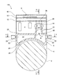
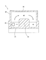
- FIG. 2 is a sectional view taken along line II-II in FIG. 3 is a cross-sectional view taken along line III-III in FIG. 4 is a cross-sectional view taken along line IV-IV in FIG.
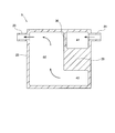
- FIG. 5 is a cross-sectional view taken along line VV in FIG.
- FIG. 6 is an enlarged view of the raised portion of FIG.
- the electric pump 100 shown in FIG. 1 is attached to an automobile engine or transmission, and is used for supplying oil to a lubrication section or supplying hydraulic pressure to hydraulic equipment driven by hydraulic pressure.
- the electric pump 100 sucks hydraulic oil as a working fluid, pressurizes and discharges the hydraulic oil, the pump 1 is connected to one side in the drive shaft direction, the motor 2 that drives the pump 1, and the side of the motor 2 ( And a motor control unit 3 that controls the driving of the motor 2.
- the pump 1 has a suction port and a discharge port (not shown), pressurizes the hydraulic oil sucked through the suction port, and supplies the pressurized hydraulic oil to a hydraulic device (not shown) from the discharge port.
- the pump 1 has a driven shaft (not shown) driven by a motor 2, and sucks and discharges hydraulic oil as the driven shaft rotates or reciprocates.
- the pump 1 may be of any type, such as a piston pump, a gear pump, a centrifugal pump, or a plunger pump, as long as the driven shaft rotates or reciprocates to suck and discharge the working fluid.
- the motor 2 has a drive shaft (not shown) that rotates or reciprocates when electric power is supplied, and the drive shaft is connected to the driven shaft of the pump 1 on one side in the drive shaft direction.
- the casing of the motor 2 is coupled to the casing of the pump 1 by coupling means (not shown) on one side in the drive shaft direction.
- the motor 2 may be of any type as long as it has a drive shaft that rotates or reciprocates when supplied with electric power.
- the casing of the motor 2 may be formed integrally with the casing of the pump 1.
- FIG. 2 is a cross-sectional view taken along the line II-II in FIG. 1, but the cross section of the motor 2 is omitted.
- the motor control unit 3 includes a drive circuit board 12 disposed on the motor 2 side in the casing 10, and a control circuit disposed parallel to the drive circuit board 12 and on the opposite side of the motor 2 with respect to the drive circuit board 12. And a substrate 13.
- the drive circuit board 12 is a board that supplies a drive current to the motor 2
- the control circuit board 13 is a board that controls the drive of the motor 2.
- the drive circuit board 12 is provided with a relatively large circuit element such as a transistor, a capacitor, and a coil
- the control circuit board 13 is provided with an IC chip such as a microcomputer.
- the drive circuit board 12 and the control circuit board 13 are connected to an external power source and other control devices via a connector (not shown), and are provided in a connection part 4 that connects the motor 2 and the motor control part 3 (not shown). It is connected to the motor 2 via a bus bar.
- the connection unit 4 is a member that not only electrically connects the motor 2 and the motor control unit 3 but also fixes the motor control unit 3 to the motor 2.
- One end of the connection unit 4 is connected to the motor control unit 3, and the other end is connected to the motor 2.
- the position where the connecting portion 4 is connected to the motor 2 is a portion closer to the other side in the drive shaft direction opposite to one side in the drive shaft direction of the motor 2 where the pump 1 is coupled to the motor 2. That is, the connecting portion 4 is connected to the motor 2 at a portion away from a portion where the pump 1 is coupled to the motor 2.
- the heat of the pump 1 is transmitted to the motor control unit 3 through the motor 2 and the connection unit 4, but the heat transfer path becomes long because the pump 1 and the connection unit 4 are arranged at positions separated from each other. As a result, the heat of the pump 1 is hardly transmitted to the motor control unit 3.
- the connection unit 4 may be integrally formed with the casing of the motor 2, the casing 10 of the motor control unit 3, or the cooling unit 5 described
- the motor control unit 3 is coupled to a cooling unit 5 that cools the motor control unit 3 with a refrigerant flowing through the motor control unit 3.
- the cooling unit 5 is disposed between the motor control unit 3 and the motor 2, and includes a heat shield wall 21 facing the motor 2 side, a cooling wall 22 facing the motor control unit 3 side, and a heat shield wall 21. And a side wall 23 connecting the cooling wall 22.
- a circulation space through which the refrigerant flows is formed in the interior surrounded by the heat shield wall 21, the cooling wall 22, and the side wall 23, a circulation space through which the refrigerant flows is formed.
- the side wall 23 is provided with an inlet 24 for introducing the refrigerant into the circulation space and an outlet 25 for discharging the refrigerant.
- the heat shield wall 21 is formed in a curved shape along the outer shape of the casing of the motor 2, and is arranged so that a predetermined gap 31 as a heat insulating layer is formed between the heat shielding wall 21 and the casing of the motor 2. Providing the predetermined gap 31 prevents the heat of the motor 2 and the heat of the pump 1 from being directly transferred to the cooling unit.
- a heat insulating material may be provided between the heat shielding wall 21 and the casing of the motor 2. Or it is good also as a structure which guides a cooling wind and driving
- the cooling wall 22 also serves as a sealing member that seals the open end of the casing 10 of the motor control unit 3. That is, the casing 10 of the motor control unit 3 is coupled to the cooling unit 5 by coupling means (not shown). Therefore, in particular, the internal space 11 on the motor 2 side from the drive circuit board 12 is cooled by the refrigerant via the cooling wall 22.
- the cooling wall 22 is formed with a raised portion 26 protruding into the internal space 11 in the motor control unit 3.
- the raised portion 26 has two inclined walls 27 inclined with respect to the vertical direction of the drive circuit board 12, and the distance between the two inclined walls 27 toward the drive circuit board 12 side. Is formed into a narrowing shape.
- a connection wall 28 for connecting the end portions of the inclined wall 27 on the drive circuit board 12 side is provided. It is good also as a shape which connected the edge parts of the inclined wall 27 directly, without providing the connection wall 28.
- the expanded internal space 11 is a space in which relatively large circuit elements such as coils and capacitors are concentrated and effectively used.
- FIG. 6 is an enlarged view in which the periphery of the raised portion 26 in FIG. 2 is enlarged.
- the main body portion 14a of the transistor 14 is fixed by a fixing means such as a screw while being in contact with the inclined surface of the inclined wall 27.
- the tip of the terminal portion 14b extending from the main body portion 14a of the transistor 14 is fixed to the drive circuit board 12 by soldering or the like. Since the angle formed between the inclined wall 27 and the drive circuit board 12 is not a right angle as described above, a gently bent portion 14c is formed in the middle of the terminal portion 14b. For this reason, the terminal portion 14 b near the main body portion 14 a is parallel to the inclined surface of the inclined wall 27, and the terminal portion 14 b near the drive circuit board 12 is perpendicular to the drive circuit board 12.
- two inclined walls 27 are provided, and when there are a large number of transistors 14, these can be arranged in a compact manner.
- the transistor 14 may be fixed to only one inclined wall 27 and the other inclined wall 27 may be a wall perpendicular to the drive circuit board 12.
- FIG. 3 is a sectional view taken along the line III-III in FIG. 1, but the section of the motor 2 is omitted.
- 4 and 5 are sectional views taken along lines IV-IV and VV in FIG. 2, respectively, but components other than the cooling unit 5 are omitted.
- the arrows in each figure indicate the flow of the refrigerant.
- the circulation space in the cooling unit 5 is provided in the inlet space 41 provided in the side wall 23 where the introduction port 24 opens, the raised portion inner space 42 formed in the raised portion 26 and connected to the inlet space 41, and the side wall 23. And a connecting space 43 that connects the raised portion inner space 42 and the flat space 44.
- the entrance space 41 is a space surrounded by the side wall 23, the guide portion 29 and the inner wall 30 provided inside the cooling portion 5.
- the guide portion 29 is a bulging portion that is formed from the heat shield wall 21 toward the raised portion 26.
- the inner wall 30 is provided in the vicinity of the lower side of the inclined wall 27 far from the introduction port 24 among the inclined walls 27 of the raised portion 26, and the cooling wall 22 and the heat shield wall 21. Are connected to the side wall 23 and the guide portion 29. For this reason, the refrigerant flowing in from the inlet 24 does not flow out of the outlet 25 directly.
- the protruding portion inner space 42 is a space surrounded by the inclined wall 27, the connecting wall 28, and the guide portion 29, and communicates with the inlet space 41 and the connecting space 43.
- the refrigerant circulates in the raised portion inner space 42 formed in the raised portion 26 by the guide portion 29. For this reason, the transistor 14 fixed to the inclined wall 27 of the raised portion 26 is cooled by the refrigerant flowing through the raised portion inner space 42.
- connection space 43 is a space formed on the opposite side of the entrance space 41 across the guide portion 29, and communicates with the raised portion inner space 42 and the flat space 44.
- the flat space 44 is a flat space formed between the cooling wall 22 and the heat shield wall 21, and is connected to the connection space 43 while the discharge port 25 is open. Yes.
- Heating elements such as capacitors and coils arranged in the internal space 11 of the motor control unit 3 are cooled by the refrigerant flowing through the flat space 44 via the cooling wall 22.
- cooling fins may be formed on the cooling wall 22.
- a partition for guiding the refrigerant in the flat space 44 may be provided so that the refrigerant flows uniformly in the flat space 44.
- the refrigerant supplied from a refrigerant supply device flows into the inlet space 41 from the inlet 24.
- the refrigerant flowing into the inlet space 41 is changed in the flow direction by the guide portion 29, flows in a direction toward the motor control portion 3 (upward in FIGS. 2 and 4), and flows into the raised portion inner space 42.
- the refrigerant that has flowed into the raised space 42 cools the transistor 14 fixed to the inclined wall 27 via the inclined wall 27.
- the refrigerant that has flowed through the raised space 42 flows into the flat space 44 through the connection space 43.
- the refrigerant that has flowed into the flat space 44 cools heating elements such as capacitors and coils disposed in the internal space 11 of the motor control unit 3 via the cooling wall 22. Thereafter, the refrigerant passes through the discharge port 25 and is returned to the refrigerant supply device.
- circuit elements such as transistors 14, capacitors, coils, and the like disposed in the internal space 11 and the internal space 11 can be efficiently used. To be cooled. As a result, an increase in the temperature of the electronic circuit fixed to the substrate is suppressed, and the motor can be operated at a higher output for a longer time.
- the transistor 14 fixed to the inclined wall 27 is efficiently cooled by the refrigerant through the inclined wall 27.
- the cooling unit 5 is arranged at a predetermined gap 31 without being in direct contact with the motor 2, the air existing between the cooling unit 5 and the motor 2 acts as a heat insulating layer, and the motor 2 and the heat of the pump 1 can be prevented from being transmitted to the motor control unit 3 through the cooling unit 5. Further, heat conduction can be further prevented by introducing cooling air or traveling air to the gap 31 between the cooling unit 5 and the motor 2. As a result, an increase in the temperature of the electronic circuit fixed to the substrate is suppressed, and the motor can be operated at a higher output for a longer time.
- connection part 4 which connects the motor control part 3 and the motor 2 is connected to the motor 2 in the part away from the part where the pump 1 is connected to the motor 2, the heat of the pump 1 is the motor control part. It becomes difficult to be transmitted to 3. As a result, it is possible to suppress the heat of the pump 1 from being transmitted to the motor control unit 3 and to suppress an increase in the temperature of the electronic circuit fixed to the substrate.
- the raised portion 26 protruding into the internal space 11 of the motor control unit 3 is provided in the cooling unit 5, the internal space 11 on the cooling unit 5 side from the drive circuit board 12 is enlarged.
- the internal space 11 can be used effectively and the circuit elements can be arranged compactly.
- the raised portion 26 has two inclined walls 27, these can be arranged in a compact manner even when a large number of transistors 14 are provided.
- the drive circuit board 12 to which the terminal portion 14b of the transistor 14 is fixed and the inclined wall 27 to which the main body portion 14a of the transistor 14 is fixed is changed due to the difference in thermal expansion, it is formed in the terminal portion 14b.
- a certain amount of displacement is absorbed by increasing or decreasing the angle of the bent portion 14c. Therefore, the plane on which the main body of the transistor is fixed and the substrate on which the terminal is fixed are orthogonal to each other, and the drive circuit board 12 is generated when a difference in thermal expansion occurs compared to the case where the bent portion is not formed in the terminal.
- the force acting on the soldering portion between the terminal portion 14b and the terminal portion 14b is reduced. As a result, it is possible to prevent the contact state between the terminal portion 14b and the drive circuit board 12 from being defective.
- the electric pump 100 may suck and discharge water or the like as the working fluid instead.
Landscapes
- Engineering & Computer Science (AREA)
- Mechanical Engineering (AREA)
- General Engineering & Computer Science (AREA)
- Microelectronics & Electronic Packaging (AREA)
- Power Engineering (AREA)
- Physics & Mathematics (AREA)
- Thermal Sciences (AREA)
- Computer Hardware Design (AREA)
- Details Of Reciprocating Pumps (AREA)
- Details And Applications Of Rotary Liquid Pumps (AREA)
- Structures Of Non-Positive Displacement Pumps (AREA)
Abstract
電動ポンプ(100)は、作動流体を吸込み加圧して吐出するポンプ(1)と、ポンプ(1)が連結されポンプ(1)を駆動するモータ(2)と、モータ(2)の側方に配置されモータ(2)の駆動を制御するモータ制御部(3)と、モータ(2)とモータ制御部(3)との間に配置され、内部を流通する冷媒によってモータ制御部(3)を冷却する冷却部(5)と、を備える。冷却部(5)は、モータ制御部(3)の内部空間(11)に突出し、冷媒が流通する流路が内部に形成された隆起部(26)を有する。
Description
本発明は、電動ポンプに関するものである。
電動ポンプとして、JP2011-94553Aには、オイルを加圧するポンプと、ポンプに連結するモータと、モータの一端に直接固定されるモータ制御部と、を備える電動オイルポンプが開示されている。
この電動オイルポンプでは、モータ制御部の内部で発生した熱を外部に放出するために、モータ制御部に冷却フィンを設けている。
しかし、上記従来の技術では、モータ制御部には、内部で発生する熱だけではなく、温度が上昇したオイルを吸排するポンプの熱もモータを介して伝わるため、モータ制御部内に配置された電子回路の温度が上昇し、モータの出力や作動時間が制限されるおそれがあった。
本発明は、このような技術的課題に鑑みてなされたものであり、モータ制御部内に配置された電子回路の温度の上昇を抑制し、モータをより高い出力で、より長い時間作動可能とすることを目的とする。
本発明のある態様によれば、作動流体を吸込み加圧して吐出するポンプと、ポンプが連結されポンプを駆動するモータと、モータの側方に配置されモータの駆動を制御するモータ制御部と、モータとモータ制御部との間に配置され、内部を流通する冷媒によってモータ制御部を冷却する冷却部と、を備え、冷却部は、モータ制御部の内部空間に突出し、冷媒が流通する流路が内部に形成された隆起部を有する電動ポンプが提供される。
以下、図面を参照して、本発明の実施形態に係る電動ポンプ100について説明する。
図1に示される電動ポンプ100は、自動車のエンジンや変速機に取り付けられ、潤滑部へのオイル供給や油圧で駆動する油圧機器に油圧を供給するために用いられる。
電動ポンプ100は、作動流体として作動油を吸込み、加圧して吐出するポンプ1と、駆動軸方向の一方側にポンプ1が連結され、ポンプ1を駆動するモータ2と、モータ2の側方(図1において上方)に配置され、モータ2の駆動を制御するモータ制御部3と、を備える。
ポンプ1は、図示しない吸込口と吐出口とを有し、吸込口を通じて吸込んだ作動油を加圧し、加圧された作動油を吐出口から図示しない油圧機器等へ供給する。ポンプ1は、モータ2により駆動される図示しない被駆動軸を有し、被駆動軸が回転または往復動することにより、作動油を吸込及び吐出する。ポンプ1は、ピストンポンプやギアポンプ,遠心ポンプ,プランジャポンプ等、被駆動軸が回転または往復動することにより、作動流体を吸込及び吐出する形式のものであればどのような形式のものでもよい。
モータ2は、電力が供給されることにより回転または往復動する図示しない駆動軸を有し、駆動軸は、駆動軸方向の一方側においてポンプ1の被駆動軸に連結される。モータ2のケーシングは、駆動軸方向の一方側において図示しない結合手段によりポンプ1のケーシングと結合されている。モータ2は、電力が供給されることにより回転または往復動する駆動軸を有するものであれば、どのような形式のものでもよい。また、モータ2のケーシングは、ポンプ1のケーシングと一体的に形成されていてもよい。
次に、図2を参照してモータ制御部3について説明する。図2は、図1のII-II線に沿う断面図であるが、モータ2の断面については省略して示している。
モータ制御部3は、ケーシング10内においてモータ2側に配置される駆動回路基板12と、駆動回路基板12と平行であって駆動回路基板12に対してモータ2と反対側に配置される制御回路基板13と、を有する。駆動回路基板12は、モータ2に駆動電流を供給する基板であり、制御回路基板13は、モータ2の駆動を制御する基板である。
駆動回路基板12には、トランジスタ、コンデンサ、コイルといった発熱性があり比較的大きい回路素子が取り付けられ、制御回路基板13には、マイコン等のICチップが取り付けられる。駆動回路基板12及び制御回路基板13は、図示しないコネクタを介して外部電源や他の制御装置に接続されるとともに、モータ2とモータ制御部3とを接続する接続部4内に設けられる図示しないバスバーを介してモータ2に接続される。
接続部4は、モータ2とモータ制御部3とを電気的に接続するだけではなく、モータ制御部3をモータ2に対して固定する部材である。接続部4の一端は、モータ制御部3に接続され、他端はモータ2に接続される。接続部4がモータ2に接続される位置は、モータ2にポンプ1が連結されるモータ2の駆動軸方向の一方側とは反対側の駆動軸方向の他方側寄りの部分である。すなわち、接続部4は、モータ2にポンプ1が連結される部分から離れた部分においてモータ2に接続される。ポンプ1の熱はモータ2及び接続部4を介してモータ制御部3へ伝わるが、ポンプ1と接続部4とは離れた位置に配置されるため、伝熱経路は長くなる。この結果、ポンプ1の熱はモータ制御部3へ伝わりにくくなる。接続部4は、モータ2のケーシング、モータ制御部3のケーシング10、または、後述の冷却部5に一体的に形成されてもよい。
モータ制御部3には、内部を流通する冷媒によってモータ制御部3を冷却する冷却部5が結合される。冷却部5は、モータ制御部3とモータ2との間に配置されており、モータ2側に面する遮熱壁21と、モータ制御部3側に面する冷却壁22と、遮熱壁21と冷却壁22とを接続する側壁23と、を有する。遮熱壁21、冷却壁22及び側壁23に囲まれた内部には、冷媒が流通する流通空間が形成される。側壁23には、流通空間内に冷媒を導入する導入口24と、冷媒を排出する排出口25と、が設けられている。
遮熱壁21は、モータ2のケーシングの外形に沿った曲面状に形成され、モータ2のケーシングとの間に断熱層としての所定の隙間31が形成されるように配置される。所定の隙間31が設けられることにより、モータ2の熱やポンプ1の熱が冷却部へ直接伝熱することが防止される。遮熱性を高めるために、遮熱壁21とモータ2のケーシングとの間に断熱材を設けてもよい。あるいは、隙間31に、冷却風や走行風を導く構成としてもよい。
冷却壁22は、モータ制御部3のケーシング10の開口端を封鎖する封止部材を兼ねている。つまり、モータ制御部3のケーシング10は、図示しない結合手段により、冷却部5に結合されている。このため、特に駆動回路基板12からモータ2側の内部空間11は、冷却壁22を介して冷媒により冷却される。
冷却壁22には、モータ制御部3内の内部空間11に突出する隆起部26が形成されている。隆起部26は、図2に示されるように、駆動回路基板12の垂直方向に対して傾斜した2つの傾斜壁27を有し、駆動回路基板12側に向かうにつれて2つの傾斜壁27間の距離が狭まる形状に形成されている。本実施形態では、傾斜壁27の駆動回路基板12側の端部間を接続する接続壁28を設けている。接続壁28を設けることなく、傾斜壁27の端部同士を直接接続した形状としてもよい。
内部空間11に突出する隆起部26が冷却部5に設けられたことによって、駆動回路基板12から冷却部5側の内部空間11は拡大される。この拡大された内部空間11は、コイルやコンデンサといった比較的大きい回路素子が集中して配置される空間となり、有効利用される。
傾斜壁27には、駆動回路基板12に配置される回路素子のうちのトランジスタ14が固定される。トランジスタ14の固定状態について、図6を参照して説明する。図6は、図2の隆起部26周辺を拡大した拡大図である。
トランジスタ14の本体部14aは、傾斜壁27の傾斜面に接触した状態でねじ等の固定手段により固定される。一方、トランジスタ14の本体部14aから延びる端子部14bの先端は、駆動回路基板12にはんだ付け等により固定される。傾斜壁27と駆動回路基板12とが成す角度は前述のように直角ではないため、端子部14bの途中には、緩やかな屈曲部14cが形成される。このため、本体部14aに近い部分の端子部14bは、傾斜壁27の傾斜面に平行となり、駆動回路基板12に近い部分の端子部14bは、駆動回路基板12に対して垂直となる。
トランジスタ14の端子部14bが屈曲部14cを有することにより、熱膨張差によってトランジスタ14の端子部14bが固定される駆動回路基板12とトランジスタ14の本体部14aが固定されている傾斜壁27との間隔が変化したとしても、この変化は屈曲部14cの角度が増減することによって吸収される。このため、熱膨張差が生じても駆動回路基板12と端子部14bとのはんだ付け部に作用する力は低減される。
本実施形態では、2つの傾斜壁27が設けられており、多数のトランジスタ14がある場合、これらをコンパクトに配置することができる。トランジスタ14が少数の場合は、一方の傾斜壁27にのみトランジスタ14を固定し、他方の傾斜壁27を駆動回路基板12に対して垂直な壁としてもよい。
次に、図2~5を参照し、冷媒が流通する冷却部5内の流通空間について説明する。図3は、図1のIII-III線に沿う断面図であるが、モータ2の断面は省略して示している。図4,図5は、それぞれ図2のIV-IV線,V-V線に沿う断面図であるが、冷却部5以外の部品は省略して示している。各図中の矢印は冷媒の流れを示している。
冷却部5内の流通空間は、側壁23に設けられた導入口24が開口する入口空間41と、隆起部26内に形成され、入口空間41に接続する隆起部内空間42と、側壁23に設けられた排出口25が開口する平坦空間44と、隆起部内空間42と平坦空間44とを接続する接続空間43と、を有する。
入口空間41は、図2及び図4に示されるように、側壁23と、冷却部5の内部に設けられたガイド部29及び内部壁30と、により囲まれた空間である。ガイド部29は、図4に示されるように、遮熱壁21から隆起部26に向けて形成される膨出部である。ガイド部29が設けられていることによって、導入口24から流入した冷媒は、冷却壁22や遮熱壁21に沿って流れることなく、モータ制御部3側に向かって流れることになる。内部壁30は、図2に示されるように、隆起部26の傾斜壁27のうち、導入口24から離れている方の傾斜壁27の下方付近に設けられ、冷却壁22と遮熱壁21と側壁23とガイド部29とに接続している。このため、導入口24から流入した冷媒は、直接排出口25から流出することはない。
隆起部内空間42は、図3に示されるように、傾斜壁27と接続壁28とガイド部29とによって囲まれた空間であり、入口空間41及び接続空間43と通じている。冷媒はガイド部29によって隆起部26内に形成された隆起部内空間42を流通することになる。このため、隆起部26の傾斜壁27に固定されたトランジスタ14は隆起部内空間42を流通する冷媒によって冷却される。
接続空間43は、図4に示されるように、ガイド部29を挟んで入口空間41と反対側に形成される空間であり、隆起部内空間42及び平坦空間44と通じている。
平坦空間44は、図2及び図5に示されるように、冷却壁22と遮熱壁21との間に形成される平坦な空間であり、排出口25が開口するとともに接続空間43と通じている。モータ制御部3の内部空間11に配置されたコンデンサやコイル等の発熱素子は、冷却壁22を介して、平坦空間44を流通する冷媒によって冷却される。冷却壁22と内部空間11内の空気との接触面積を増やすために、冷却壁22に冷却フィンを形成してもよい。また、冷媒が平坦空間44内を均一に流れるように、平坦空間44内に冷媒を誘導する仕切りを設けてもよい。
次に、冷却部5を流通する冷媒による冷却作用について説明する。
図示しない冷媒供給装置から供給された冷媒は、導入口24から入口空間41に流入する。入口空間41に流入した冷媒は、ガイド部29によって流れる方向が変化され、モータ制御部3に向かう方向(図2及び図4において上方)に流れ、隆起部内空間42に流入する。隆起部内空間42に流入した冷媒は、傾斜壁27を介して、傾斜壁27に固定されたトランジスタ14を冷却する。隆起部内空間42を流通した冷媒は接続空間43を通じて平坦空間44に流入する。平坦空間44に流入した冷媒は、冷却壁22を介してモータ制御部3の内部空間11に配置されたコンデンサやコイル等の発熱素子を冷却する。その後、冷媒は排出口25を通り冷媒供給装置へ戻される。
以上の実施形態によれば、以下に示す効果を奏する。
モータ制御部3の内部空間11に突出する隆起部26が冷却部5に設けられているため、内部空間11及び内部空間11に配置されるトランジスタ14やコンデンサ、コイル等の回路素子は効率的に冷却される。この結果、基板に固定される電子回路の温度の上昇が抑制され、モータをより高い出力で、より長い時間作動させることが可能となる。特に傾斜壁27に固定されたトランジスタ14は、傾斜壁27を介して冷媒により効率的に冷却される。
また、冷却部5は、モータ2と直接接触することなく、所定の隙間31だけ離れて配置されているため、冷却部5とモータ2との間に存在する空気が断熱層として作用し、モータ2の熱やポンプ1の熱が冷却部5を介してモータ制御部3へ伝わることを防止することができる。また、冷却部5とモータ2との間の隙間31に、冷却風や走行風を導くことによりさらに伝熱を防止することができる。この結果、基板に固定される電子回路の温度の上昇が抑制され、モータをより高い出力で、より長い時間作動させることが可能となる。
また、モータ制御部3とモータ2とを接続する接続部4は、モータ2にポンプ1が連結される部分から離れた部分においてモータ2に接続されているため、ポンプ1の熱はモータ制御部3へ伝わりにくくなる。この結果、ポンプ1の熱がモータ制御部3へ伝わることが抑制され、基板に固定される電子回路の温度の上昇を抑制することができる。
また、モータ制御部3の内部空間11に突出する隆起部26が冷却部5に設けられたことによって、駆動回路基板12から冷却部5側の内部空間11は拡大される。この拡大された内部空間11にコイルやコンデンサといった比較的大きい回路素子を集中して配置することにより、内部空間11を有効利用し、回路素子をコンパクトに配置することができる。また、隆起部26には2つの傾斜壁27があるため、トランジスタ14を多数有する場合であってもこれらをコンパクトに配置することができる。
また、熱膨張差によりトランジスタ14の端子部14bが固定される駆動回路基板12とトランジスタ14の本体部14aが固定されている傾斜壁27との間隔が変化したとしても、端子部14bに形成された屈曲部14cの角度が増減することによって、ある程度の変位が吸収される。このため、トランジスタの本体部が固定される平面と端子部が固定される基板とが直交し、端子部に屈曲部が形成されない場合に比べて、熱膨張差が生じたときに駆動回路基板12と端子部14bとのはんだ付け部に作用する力は低減される。この結果、端子部14bと駆動回路基板12との接触状態が不良となることを防止できる。
以上、本発明の実施形態について説明したが、上記実施形態は本発明の適用例の一部を示したに過ぎず、本発明の技術的範囲を上記実施形態の具体的構成に限定する趣旨ではない。
例えば、上記実施形態に係る電動ポンプ100は、作動流体として作動油を吸込及び吐出するものであるが、これに代えて、作動流体として水等を吸込及び吐出するものであってもよい。
本願は2014年4月16日に日本国特許庁に出願された特願2014-84957に基づく優先権を主張し、この出願の全ての内容は参照により本明細書に組み込まれる。
Claims (5)
- 作動流体を吐出する電動ポンプであって、
作動流体を吸込み、加圧して吐出するポンプと、
前記ポンプが連結され、前記ポンプを駆動するモータと、
前記モータの側方に配置され、前記モータの駆動を制御するモータ制御部と、
前記モータと前記モータ制御部との間に配置され、内部を流通する冷媒によって前記モータ制御部を冷却する冷却部と、
を備え、
前記冷却部は、前記モータ制御部の内部空間に突出し、冷媒が流通する流路が内部に形成された隆起部を有する電動ポンプ。 - 請求項1に記載の電動ポンプであって、
前記冷却部は、冷媒が前記隆起部の内部に形成された流路を通るように導くガイド部をさらに有する電動ポンプ。 - 請求項1に記載の電動ポンプであって、
前記隆起部は、前記モータ制御部内に配置される基板の垂直方向に対して傾斜した傾斜面を有し、
端子部が前記基板に固定され、本体部が前記傾斜面に固定される回路素子をさらに有する電動ポンプ。 - 請求項1に記載の電動ポンプであって、
前記モータと前記冷却部との間に設けられ、前記モータから前記冷却部への伝熱を抑制する断熱層をさらに備える電動ポンプ。 - 請求項1に記載の電動ポンプであって、
前記モータ制御部と前記モータとを電気的に接続するとともに、前記モータ制御部を前記モータに対して固定する接続部をさらに備え、
前記接続部は、前記モータに前記ポンプが連結される部分から離れた部分において前記モータに接続される電動ポンプ。
Priority Applications (2)
| Application Number | Priority Date | Filing Date | Title |
|---|---|---|---|
| CN201580014014.1A CN106103996B (zh) | 2014-04-16 | 2015-04-02 | 电动泵 |
| US15/125,593 US20170002807A1 (en) | 2014-04-16 | 2015-04-02 | Electric pump |
Applications Claiming Priority (2)
| Application Number | Priority Date | Filing Date | Title |
|---|---|---|---|
| JP2014-084957 | 2014-04-16 | ||
| JP2014084957A JP6225064B2 (ja) | 2014-04-16 | 2014-04-16 | 電動ポンプ |
Publications (1)
| Publication Number | Publication Date |
|---|---|
| WO2015159723A1 true WO2015159723A1 (ja) | 2015-10-22 |
Family
ID=54323935
Family Applications (1)
| Application Number | Title | Priority Date | Filing Date |
|---|---|---|---|
| PCT/JP2015/060504 Ceased WO2015159723A1 (ja) | 2014-04-16 | 2015-04-02 | 電動ポンプ |
Country Status (4)
| Country | Link |
|---|---|
| US (1) | US20170002807A1 (ja) |
| JP (1) | JP6225064B2 (ja) |
| CN (1) | CN106103996B (ja) |
| WO (1) | WO2015159723A1 (ja) |
Families Citing this family (6)
| Publication number | Priority date | Publication date | Assignee | Title |
|---|---|---|---|---|
| DE102016002336B4 (de) | 2016-02-29 | 2021-12-09 | Volkswagen Aktiengesellschaft | Kompakte Baueinheit für ein Kraftfahrzeug, insbesondere eine als Pumpenantrieb ausgeführte kompakte Baueinheit aufweisend einen Elektromotor und ein Steuergerät, beziehungsweise Getriebegehäuse oder Tankgehäuse für ein Kraftfahrzeug mit der zuvor genannten kompakten Baueinheit |
| JP7039990B2 (ja) * | 2017-12-21 | 2022-03-23 | 日本電産トーソク株式会社 | 電動オイルポンプ |
| AU2020221195B2 (en) * | 2019-02-12 | 2023-10-05 | Terzo Power Systems, LLC | Valveless hydraulic system |
| JP7281687B2 (ja) * | 2019-03-28 | 2023-05-26 | ニデックパワートレインシステムズ株式会社 | 電動オイルポンプ |
| JP7441073B2 (ja) * | 2020-02-26 | 2024-02-29 | 株式会社ジェイテクトフルードパワーシステム | 油圧装置 |
| CN116877418B (zh) * | 2023-09-07 | 2023-11-28 | 福建省福安市力德泵业有限公司 | 一种利用输送流体进行冷却的密封往复泵 |
Citations (7)
| Publication number | Priority date | Publication date | Assignee | Title |
|---|---|---|---|---|
| JP2005054716A (ja) * | 2003-08-06 | 2005-03-03 | Matsushita Electric Ind Co Ltd | 電動圧縮機 |
| JP2005171951A (ja) * | 2003-12-15 | 2005-06-30 | Matsushita Electric Ind Co Ltd | 電動圧縮機 |
| JP2010112180A (ja) * | 2008-11-04 | 2010-05-20 | Toyota Industries Corp | 電動圧縮機 |
| JP2010144620A (ja) * | 2008-12-18 | 2010-07-01 | Aisin Seiki Co Ltd | 電動ポンプ |
| US20110008197A1 (en) * | 2008-02-29 | 2011-01-13 | Doowon Technical College | Inverter type scroll compressor |
| JP2012189013A (ja) * | 2011-03-11 | 2012-10-04 | Jtekt Corp | 電動ポンプユニット |
| US20130302142A1 (en) * | 2012-05-10 | 2013-11-14 | Ji-Ee Industry Co., Ltd | Electric fluid pump |
Family Cites Families (7)
| Publication number | Priority date | Publication date | Assignee | Title |
|---|---|---|---|---|
| JP4200654B2 (ja) * | 2000-12-19 | 2008-12-24 | 株式会社デンソー | 電動式冷凍サイクル装置 |
| DE10302791B4 (de) * | 2002-01-30 | 2016-03-17 | Denso Corporation | Elektrokompressor |
| JP2004044554A (ja) * | 2002-07-15 | 2004-02-12 | Toyota Industries Corp | 電動コンプレッサ |
| JP4310683B2 (ja) * | 2003-05-13 | 2009-08-12 | アイシン・エィ・ダブリュ株式会社 | 電動機内蔵駆動装置 |
| JP2005253167A (ja) * | 2004-03-03 | 2005-09-15 | Hitachi Ltd | 車両駆動装置及びそれを用いた電動4輪駆動車両 |
| JP2007162661A (ja) * | 2005-12-16 | 2007-06-28 | Denso Corp | 電動圧縮機 |
| KR20120016833A (ko) * | 2010-08-17 | 2012-02-27 | 학교법인 두원학원 | 차량용 전동식압축기 |
-
2014
- 2014-04-16 JP JP2014084957A patent/JP6225064B2/ja active Active
-
2015
- 2015-04-02 US US15/125,593 patent/US20170002807A1/en not_active Abandoned
- 2015-04-02 CN CN201580014014.1A patent/CN106103996B/zh not_active Expired - Fee Related
- 2015-04-02 WO PCT/JP2015/060504 patent/WO2015159723A1/ja not_active Ceased
Patent Citations (7)
| Publication number | Priority date | Publication date | Assignee | Title |
|---|---|---|---|---|
| JP2005054716A (ja) * | 2003-08-06 | 2005-03-03 | Matsushita Electric Ind Co Ltd | 電動圧縮機 |
| JP2005171951A (ja) * | 2003-12-15 | 2005-06-30 | Matsushita Electric Ind Co Ltd | 電動圧縮機 |
| US20110008197A1 (en) * | 2008-02-29 | 2011-01-13 | Doowon Technical College | Inverter type scroll compressor |
| JP2010112180A (ja) * | 2008-11-04 | 2010-05-20 | Toyota Industries Corp | 電動圧縮機 |
| JP2010144620A (ja) * | 2008-12-18 | 2010-07-01 | Aisin Seiki Co Ltd | 電動ポンプ |
| JP2012189013A (ja) * | 2011-03-11 | 2012-10-04 | Jtekt Corp | 電動ポンプユニット |
| US20130302142A1 (en) * | 2012-05-10 | 2013-11-14 | Ji-Ee Industry Co., Ltd | Electric fluid pump |
Also Published As
| Publication number | Publication date |
|---|---|
| JP2015203409A (ja) | 2015-11-16 |
| JP6225064B2 (ja) | 2017-11-01 |
| CN106103996B (zh) | 2018-01-05 |
| US20170002807A1 (en) | 2017-01-05 |
| CN106103996A (zh) | 2016-11-09 |
Similar Documents
| Publication | Publication Date | Title |
|---|---|---|
| JP6225064B2 (ja) | 電動ポンプ | |
| JP5002522B2 (ja) | 電子機器用冷却装置及びこれを備えた電子機器 | |
| KR101601099B1 (ko) | 냉각수 유동 통로를 갖는 전동식 워터 펌프 | |
| JP7029437B2 (ja) | 内部能動冷却機能付きコントローラおよびモータ内蔵ポンプアセンブリ | |
| KR102067140B1 (ko) | 전동식 압축기 | |
| ITUA20163927A1 (it) | Macchina elettrica ad architettura tangenziale con raffreddamento ad aria migliorato | |
| CN103443474A (zh) | 电动车辆冷却剂泵 | |
| US8157542B2 (en) | Brushless motor fuel pump with control electronics arrangement | |
| CN110171281A (zh) | 驱动装置的冷却结构 | |
| TWI661659B (zh) | 一體化馬達及一體化散熱系統 | |
| KR101712706B1 (ko) | 자동차 분야에 사용되는 전기 기계 | |
| US20220346286A1 (en) | Power inverter | |
| ITUA20163925A1 (it) | Macchina elettrica ad architettura tangenziale con raffreddamento ad aria migliorato | |
| JP5252052B2 (ja) | 油圧ユニット | |
| CN111566913A (zh) | 用于控制电动机的控制装置 | |
| CN103032351B (zh) | 通风机装置 | |
| KR102387710B1 (ko) | 전동식 오일펌프 | |
| KR100677624B1 (ko) | 액체냉각시스템 및 이를 채용한 전자기기 | |
| KR20100058463A (ko) | 유체 펌프 | |
| US11026353B2 (en) | Arrangement having a housing and a power electronics circuit arranged on a housing base in the housing | |
| JP2015117676A (ja) | 空気圧縮機 | |
| JP6413640B2 (ja) | 圧縮機 | |
| JP5058712B2 (ja) | 回転電機装置 | |
| FI121949B (fi) | Menetelmä ja järjestely laitekotelon jäähdyttämiseksi | |
| KR101669702B1 (ko) | 내장형 컴퓨터 전자제어장치의 냉각 장치 |
Legal Events
| Date | Code | Title | Description |
|---|---|---|---|
| 121 | Ep: the epo has been informed by wipo that ep was designated in this application |
Ref document number: 15779409 Country of ref document: EP Kind code of ref document: A1 |
|
| WWE | Wipo information: entry into national phase |
Ref document number: 15125593 Country of ref document: US |
|
| NENP | Non-entry into the national phase |
Ref country code: DE |
|
| 122 | Ep: pct application non-entry in european phase |
Ref document number: 15779409 Country of ref document: EP Kind code of ref document: A1 |