WO2015159489A1 - 車載カメラの取り付け誤差表示制御装置及び取り付け誤差検出装置 - Google Patents
車載カメラの取り付け誤差表示制御装置及び取り付け誤差検出装置 Download PDFInfo
- Publication number
- WO2015159489A1 WO2015159489A1 PCT/JP2015/001678 JP2015001678W WO2015159489A1 WO 2015159489 A1 WO2015159489 A1 WO 2015159489A1 JP 2015001678 W JP2015001678 W JP 2015001678W WO 2015159489 A1 WO2015159489 A1 WO 2015159489A1
- Authority
- WO
- WIPO (PCT)
- Prior art keywords
- vehicle
- vehicle camera
- feature point
- image
- camera
- Prior art date
- Legal status (The legal status is an assumption and is not a legal conclusion. Google has not performed a legal analysis and makes no representation as to the accuracy of the status listed.)
- Ceased
Links
Images



Classifications
-
- G—PHYSICS
- G06—COMPUTING OR CALCULATING; COUNTING
- G06T—IMAGE DATA PROCESSING OR GENERATION, IN GENERAL
- G06T7/00—Image analysis
- G06T7/80—Analysis of captured images to determine intrinsic or extrinsic camera parameters, i.e. camera calibration
-
- B—PERFORMING OPERATIONS; TRANSPORTING
- B60—VEHICLES IN GENERAL
- B60R—VEHICLES, VEHICLE FITTINGS, OR VEHICLE PARTS, NOT OTHERWISE PROVIDED FOR
- B60R11/00—Arrangements for holding or mounting articles, not otherwise provided for
- B60R11/04—Mounting of cameras operative during drive; Arrangement of controls thereof relative to the vehicle
-
- G—PHYSICS
- G06—COMPUTING OR CALCULATING; COUNTING
- G06T—IMAGE DATA PROCESSING OR GENERATION, IN GENERAL
- G06T7/00—Image analysis
- G06T7/0002—Inspection of images, e.g. flaw detection
- G06T7/0004—Industrial image inspection
- G06T7/0006—Industrial image inspection using a design-rule based approach
-
- G—PHYSICS
- G06—COMPUTING OR CALCULATING; COUNTING
- G06T—IMAGE DATA PROCESSING OR GENERATION, IN GENERAL
- G06T7/00—Image analysis
- G06T7/70—Determining position or orientation of objects or cameras
- G06T7/73—Determining position or orientation of objects or cameras using feature-based methods
-
- H—ELECTRICITY
- H04—ELECTRIC COMMUNICATION TECHNIQUE
- H04N—PICTORIAL COMMUNICATION, e.g. TELEVISION
- H04N23/00—Cameras or camera modules comprising electronic image sensors; Control thereof
- H04N23/60—Control of cameras or camera modules
- H04N23/63—Control of cameras or camera modules by using electronic viewfinders
-
- H—ELECTRICITY
- H04—ELECTRIC COMMUNICATION TECHNIQUE
- H04N—PICTORIAL COMMUNICATION, e.g. TELEVISION
- H04N5/00—Details of television systems
- H04N5/222—Studio circuitry; Studio devices; Studio equipment
- H04N5/262—Studio circuits, e.g. for mixing, switching-over, change of character of image, other special effects ; Cameras specially adapted for the electronic generation of special effects
- H04N5/265—Mixing
-
- B—PERFORMING OPERATIONS; TRANSPORTING
- B60—VEHICLES IN GENERAL
- B60R—VEHICLES, VEHICLE FITTINGS, OR VEHICLE PARTS, NOT OTHERWISE PROVIDED FOR
- B60R2300/00—Details of viewing arrangements using cameras and displays, specially adapted for use in a vehicle
- B60R2300/40—Details of viewing arrangements using cameras and displays, specially adapted for use in a vehicle characterised by the details of the power supply or the coupling to vehicle components
- B60R2300/402—Image calibration
-
- B—PERFORMING OPERATIONS; TRANSPORTING
- B60—VEHICLES IN GENERAL
- B60R—VEHICLES, VEHICLE FITTINGS, OR VEHICLE PARTS, NOT OTHERWISE PROVIDED FOR
- B60R2300/00—Details of viewing arrangements using cameras and displays, specially adapted for use in a vehicle
- B60R2300/60—Details of viewing arrangements using cameras and displays, specially adapted for use in a vehicle characterised by monitoring and displaying vehicle exterior scenes from a transformed perspective
- B60R2300/607—Details of viewing arrangements using cameras and displays, specially adapted for use in a vehicle characterised by monitoring and displaying vehicle exterior scenes from a transformed perspective from a bird's eye viewpoint
-
- B—PERFORMING OPERATIONS; TRANSPORTING
- B60—VEHICLES IN GENERAL
- B60R—VEHICLES, VEHICLE FITTINGS, OR VEHICLE PARTS, NOT OTHERWISE PROVIDED FOR
- B60R2300/00—Details of viewing arrangements using cameras and displays, specially adapted for use in a vehicle
- B60R2300/80—Details of viewing arrangements using cameras and displays, specially adapted for use in a vehicle characterised by the intended use of the viewing arrangement
- B60R2300/8066—Details of viewing arrangements using cameras and displays, specially adapted for use in a vehicle characterised by the intended use of the viewing arrangement for monitoring rearward traffic
-
- G—PHYSICS
- G06—COMPUTING OR CALCULATING; COUNTING
- G06T—IMAGE DATA PROCESSING OR GENERATION, IN GENERAL
- G06T2207/00—Indexing scheme for image analysis or image enhancement
- G06T2207/30—Subject of image; Context of image processing
- G06T2207/30244—Camera pose
-
- G—PHYSICS
- G06—COMPUTING OR CALCULATING; COUNTING
- G06T—IMAGE DATA PROCESSING OR GENERATION, IN GENERAL
- G06T2207/00—Indexing scheme for image analysis or image enhancement
- G06T2207/30—Subject of image; Context of image processing
- G06T2207/30248—Vehicle exterior or interior
- G06T2207/30252—Vehicle exterior; Vicinity of vehicle
Definitions
- the present disclosure relates to an in-vehicle camera attachment error display control device and an attachment error detection device suitable for determining whether or not the position of the in-vehicle camera is an appropriate position.
- an effective area in a captured image is detected so that two markers provided on the left and right fenders of the vehicle are detected from captured images around the vehicle by an in-vehicle camera, and each marker is set at a predetermined position.
- each marker is set at a predetermined position.
- the present disclosure has been made in view of such a problem, and it is possible to determine whether or not the mounting position of the in-vehicle camera is an appropriate position without using a marker provided on the vehicle. It is an object of the present invention to provide a device and a mounting error detection device.
- An in-vehicle camera attachment error display control device includes an input unit that receives an image captured by an in-vehicle camera, and a vehicle that is reflected in an image captured by the in-vehicle camera when the in-vehicle camera is attached to an appropriate position.
- a storage unit that stores position information of the feature points.
- the feature point superimposing unit superimposes an image based on the feature point on the captured image input from the input unit based on the position information stored in the storage unit, and the image output unit generates an image based on the feature point.
- the superimposed captured image is output to a display device.
- the user displays the output image from the image output unit on the display device and confirms the display screen, so that the mounting position of the in-vehicle camera is It is possible to easily determine whether or not there is a deviation from an appropriate position (in other words, whether or not there is an attachment error) or how much the deviation is from the appropriate position.
- the in-vehicle camera mounting error display control device of the present disclosure it is possible to determine whether or not the in-vehicle camera is attached to an appropriate position without providing a marker on the vehicle body. It is not necessary to arrange at a position, and can be applied to any vehicle-mounted camera.
- An in-vehicle camera mounting error detection device includes an input unit that receives an image captured by an in-vehicle camera, and a vehicle that is reflected in an image captured by the in-vehicle camera when the in-vehicle camera is mounted at an appropriate position. And a storage unit for storing position information of the feature points.
- the feature point detection unit detects the feature point of the vehicle from the captured image input from the input unit, and the determination unit is stored in the storage unit and the position of the feature point in the detected captured image. Based on the obtained position information, it is determined whether or not the mounting position of the in-vehicle camera is an appropriate position. Further, when the determination unit determines that the mounting position of the in-vehicle camera is an inappropriate position, the notification unit notifies the mounting failure of the in-vehicle camera.
- the in-vehicle camera mounting error detection device of the present disclosure when the in-vehicle camera mounting position is deviated from the appropriate position by automatically determining whether the in-vehicle camera mounting position is in an appropriate position. Can notify the user to that effect.
- the in-vehicle camera attachment error detection device of the present disclosure it is possible to detect whether the in-vehicle camera attachment position is in an appropriate position (in other words, attachment error) without using a marker provided on the vehicle body. Therefore, it can be applied to any in-vehicle camera.
- FIG. 1 is a block diagram showing the configuration of the image processing system according to the first embodiment.
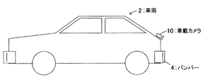
- FIG. 2 is an explanatory diagram showing the mounting position of the in-vehicle camera on the vehicle
- FIG. 3 is a flowchart showing an initial setting process executed in the image processing apparatus.
- FIG. 4 is a flowchart showing an image display process executed by the image processing apparatus.
- FIG. 5 is an explanatory diagram illustrating a display screen of the display device by the captured image display process.
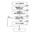
- FIG. 6 is a flowchart showing the attachment error determination process of the second embodiment.
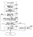
- FIG. 7 is a flowchart showing the attachment error determination process of the third embodiment.
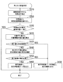
- FIG. 8 is a flowchart showing the attachment error determination process of the fourth embodiment.
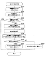
- FIG. 9 is a flowchart showing the attachment error determination process of the fifth embodiment.
- the image processing system of this embodiment includes an in-vehicle camera 10, an image processing device 20, and a display device 30.
- the in-vehicle camera 10 is a camera having an image sensor such as a CCD or a CMOS, and is installed at the upper rear part of the vehicle 2 as shown in FIG.
- the vehicle-mounted camera 10 outputs the captured image of the rear of the vehicle to the image processing device 20 at a predetermined frequency (for example, 60 frames per second).
- the in-vehicle camera 10 is attached to the vehicle 2 as a feature point of the vehicle 2 so that the bumper 4 behind the vehicle is reflected in the captured image.
- the display device 30 is configured by a liquid crystal display, an organic EL display, or the like, and displays an image processed by the image processing device 20 based on an image captured by the in-vehicle camera 10.
- the image processing apparatus 20 corresponds to the in-vehicle camera mounting error display control apparatus of the present disclosure, and includes an input unit 22, an operation unit 24, a storage unit 26, and a control unit 28.
- the input unit 22 includes a storage device such as a DRAM, and captures captured images sequentially output from the in-vehicle camera 10 and stores them for a predetermined time (for example, the past 10 seconds).
- a storage device such as a DRAM
- the operation unit 24 is for a user such as a driver to input various operation instructions to the control unit 28, and is installed on the touch panel provided on the display surface of the display device 30 or around the display device 30. It consists of a mechanical key switch and the like.
- the storage unit 26 is a non-volatile storage device such as a flash memory, and is a device for storing a program executed by the control unit 28 and data necessary for processing an image captured by the in-vehicle camera 10.
- the position information of the in-vehicle camera 10 in addition to the conversion data necessary for converting the image captured by the in-vehicle camera 10 into the display image on the display device 30, the position information of the in-vehicle camera 10, the imaging Feature point information for detecting a feature point of the vehicle (bumper 4 in the present embodiment) from the image, reference position information indicating the position of the feature point in the captured image when the in-vehicle camera 10 is at an appropriate position, Etc. are memorized.
- the position information of the in-vehicle camera 10 is, for example, information indicating the position of the in-vehicle camera 10 when the in-vehicle camera 10 is installed at a proper position and calibrated. It is composed of information indicating the position on the axis (that is, x, y, z coordinates) and the inclination (roll, pitch, yaw) around each axis.
- the feature point information is shape data necessary for recognizing the bumper 4 that is the feature point of the vehicle body from the image captured by the in-vehicle camera 10, and the reference position information of the feature point is the bumper in the captured image.
- 4 is coordinate information representing the position of 4 (for example, the center position).
- control unit 28 is configured by a microcomputer including a CPU, a RAM, a ROM, an I / O, and the like.
- the control unit 28 executes an initial setting process shown in FIG.
- the image display process shown in FIG. 4 is executed.
- the initial setting process shown in FIG. 3 is a process executed to calibrate the in-vehicle camera 10 when the in-vehicle camera 10 is attached to an appropriate position in a factory or the like.
- S110 a known calibration process is performed.
- the calibration process of S110 in addition to the calibration result (for example, conversion data required to convert an image captured by the in-vehicle camera 10 into a display image (for example, a bird's-eye view image) on the display device 30), calibration is performed.
- the position information of the in-vehicle camera 10 when it is performed is also stored.
- an image captured by the in-vehicle camera 10 is captured from the input unit 22, and the bumper 4 that is a feature point of the vehicle 2 in the captured image is detected based on the shape data stored in the storage unit 26 in advance.
- the position of the feature point (bumper 4) detected in S130 on the captured image is stored in the storage unit 26 as the reference position information of the feature point, and the initial setting process ends.
- the image display process shown in FIG. 4 is performed by converting the image captured by the in-vehicle camera 10 into image data for display based on the conversion data obtained by the calibration described above.
- This is a process for displaying an image (for example, a bird's-eye view image) on the display device 30 by outputting to the device 30.
- the reference position information of the feature point (bumper 4) is read from the storage unit 26 in S210.
- an image representing the reference position of the feature point (bumper 4) in the captured image acquired from the input unit 22 is superimposed on a pattern indicated by a one-dot chain line.
- the one-dot chain line representing the reference position of the feature point is given as an example of the “image based on the feature point”, but the present disclosure is not limited to this.
- the reference position of the bumper is the center.
- the image indicating the predetermined width may be superimposed and displayed as an “image based on feature points”.
- the captured image obtained by superimposing the image representing the reference position of the feature point (bumper 4) in S220 is converted into display image data based on the conversion data stored in the storage unit 26, and the display device 30 is displayed. Output to.
- the position of the feature point when the in-vehicle camera 10 is attached to an appropriate position is displayed on the display device 30 together with the captured image in which the bumper 4 as the feature point is reflected as shown by a solid line in FIG. An image to be displayed is displayed.
- the image processing system of the second embodiment Similar to the image processing system of the first embodiment shown in FIG. 1, the image processing system of the second embodiment includes an in-vehicle camera 10, an image processing device 20, and a display device 30.
- the difference from the image processing system according to the first embodiment is that, in the image processing apparatus 20, the control unit 28 executes the attachment error determination process of FIG. It is a functioning point.
- control unit 28 executes the initial setting process shown in FIG. 3 as in the first embodiment.
- image display process shown in FIG. 4 may be executed in the same manner as in the first embodiment, and only the image captured by the in-vehicle camera 10 is displayed by simply executing the processes of S210 and S230. You may make it display on the apparatus 30.
- FIG. 4
- 6 is, for example, a process executed when the ignition switch of the vehicle 2 is turned on and the image processing apparatus 20 is activated.
- an image captured by the in-vehicle camera 10 is captured from the input unit 22, and based on the shape data stored in advance in the storage unit 26, it is a feature point of the vehicle 2 in the captured image.
- the bumper 4 is detected.
- the reference position information of the feature point (bumper 4) is read from the storage unit 26.
- the position of the feature point (bumper 4) detected in S310 in the captured image is read in S320. It is determined whether or not it matches the reference position obtained from the reference position information.
- the attachment error determination process is terminated.
- the process proceeds to S340. Then, the user is notified of the mounting failure of the in-vehicle camera 10, and the mounting error determination process is terminated.
- the notification of the mounting failure of the in-vehicle camera 10 can be executed by, for example, displaying a message indicating that the mounting failure of the in-vehicle camera 10 has occurred on the display device 30. You may make it notify by a voice from a not-shown), or you may make it notify by lighting the alarm lamp (not shown) for abnormality notification.
- the control unit 28 of the image processing device 20 functions as the mounting error detection device for the in-vehicle camera of the present disclosure, so that the feature point ( When the position of the bumper 4) does not coincide with the reference position stored as the reference position information in the storage unit 26, the mounting failure of the in-vehicle camera is notified.
- the image processing system of the present embodiment when the mounting position of the in-vehicle camera 10 is shifted from an appropriate position when the in-vehicle camera 10 is calibrated, the user is notified of that fact. Thus, the position adjustment of the in-vehicle camera 10 can be prompted.
- the image processing system according to the third embodiment corrects the display image data when the positional deviation of the feature point is detected on the image captured by the in-vehicle camera 10 in the image processing system according to the second embodiment, and the display device In FIG. 30, a captured image can be displayed normally.
- the attachment error determination process will be described, and description of other configurations will be omitted.
- the attachment error determination process is terminated, and the position of the feature point does not match the reference position. Then, the process proceeds to S410, and the correction amount of the position information of the in-vehicle camera 10 required to minimize the positional deviation amount (zero) is calculated based on the positional deviation amount of the feature point with respect to the reference position.
- the position information when the calibration of the in-vehicle camera 10 is performed is stored in the storage unit 26, in S410, the deviation of the feature point from the reference position on the captured image is determined based on the position information. The amount of correction of the position of the in-vehicle camera 10 necessary for the elimination is calculated.
- the display image data is corrected based on the correction amount calculated in S410.
- the display device 30 displays a normal image in which the position of the feature point on the captured image is substantially the reference position.
- a desired image (bird's-eye image or the like) can be normally displayed on the display device 30 even if the mounting position of the in-vehicle camera 10 is shifted from the appropriate position. Become.
- the notification of the mounting failure of the in-vehicle camera 10 and the inquiry about the necessity of correction of the display image may be performed by displaying a message on the display device 30 or by sound output using a speaker (not shown). May be.
- S450 as a result of inquiring whether or not the display image needs to be corrected in S440, it is determined whether or not an input indicating that the display image needs to be corrected is input via the operation unit 24. If correction of the display image is necessary, the process proceeds to S430. If correction of the display image is not necessary, the process proceeds to S460, and the display image data is output to the display device 30 as it is without correction. Thus, the output operation of the display image data is set.
- the user can detect the fact by the notification from the image processing device 20 and adjust the position of the in-vehicle camera 10 and adjust the position. Until this is done, the display image on the display device 30 can be corrected and a normal image can be displayed on the display device 30.
- the cause of the positional deviation is the attachment of the in-vehicle camera 10. It is possible to determine whether it is due to displacement of the position (in other words, poor attachment) or due to deformation of the vehicle body and to notify the user.
- the attachment error determination process will be described, and description of other configurations will be omitted.
- a feature point is detected from the captured image in S310 and stored in S320.
- the reference position information of the feature point is read from the unit 26, and it is determined in S330 whether the position of the feature point matches the reference position.
- the current position information of the in-vehicle camera 10 is calculated based on the positional deviation amount of the feature point on the captured image with respect to the reference position and the position information of the in-vehicle camera 10 stored in the storage unit 26.
- each parameter (coordinates in the x, y, and z axis directions and roll, pitch, and yaw angles described above) constituting the position information of the in-vehicle camera 10 stored in the storage unit 26 is predetermined.
- the current position information of the in-vehicle camera 10 is calculated by searching for each parameter that minimizes the positional deviation amount of the feature point on the captured image. To do.
- the captured image by the in-vehicle camera 10 is corrected based on the current position information of the in-vehicle camera 10 obtained in S510, and in the subsequent S530, the corrected captured image (corrected image) is corrected.
- a feature point is detected, and a similarity between the position of the feature point and a reference position stored in the storage unit 26 is calculated.
- S540 it is determined whether or not the similarity obtained in S530 is greater than or equal to a threshold value. If the similarity is equal to or greater than the threshold value, the process proceeds to S550, where it is determined that the cause of the misregistration of the feature point is due to poor mounting of the in-vehicle camera, and that is notified to the user. The attachment error determination process is terminated.
- the user can detect a mounting failure of the in-vehicle camera 10 or a deformation of the vehicle body based on the notification and take measures such as vehicle repair.
- the image processing system of the fifth embodiment is based on whether the misalignment of the feature points on the image captured by the in-vehicle camera 10 is due to poor mounting of the in-vehicle camera 10 or due to deformation of the vehicle body. It is possible to determine whether it is present and notify the user.
- the process proceeds to S610, and the position shift of the feature point is performed. It is estimated whether the cause of this is due to the displacement of the in-vehicle camera 10 in the height direction (z-axis direction) or the elevation angle direction (pitch direction).
- the coordinates in the height direction (z-axis direction) and the pitch angle around the y-axis are set to a predetermined value.
- the captured image is corrected, and by determining whether the positional deviation amount of the feature point on the captured image is minimized, the cause of the positional deviation is caused by the in-vehicle camera 10. It is estimated whether it is due to displacement in the height direction or due to displacement in the elevation angle direction.
- S620 if it is determined that the cause of the positional deviation of the feature point on the captured image is not due to the displacement of the in-vehicle camera 10 in the height direction or the elevation direction, the cause is determined in S640. Determines that it is due to vehicle body deformation, notifies the user to that effect, and ends the camera attachment error determination processing.
- the vehicle-mounted camera 10 is normally attached to the vehicle 2 so as to be displaceable in the vertical (z-axis) direction and the elevation angle (pitch) direction, and the front-rear (x-axis) / left-right (y-axis) This is because there is no displacement in the roll angle and yaw angle directions.
- the image processing system of the present embodiment it is specified whether the positional deviation of the feature point on the image captured by the in-vehicle camera 10 is due to poor mounting of the in-vehicle camera 10 or due to deformation of the vehicle body.
- the control unit since only the parameters in the vertical (z-axis) direction and the elevation angle (pitch) direction in the positional information of the in-vehicle camera 10 need be changed, the control unit is compared with the image processing system of the fourth embodiment.
- the arithmetic processing at 28 can be simplified.
- this indication is not limited to the above-mentioned embodiment, and can take various modes within the range which does not deviate from the gist of this indication.
- the vehicle-mounted camera 10 is described as being disposed behind the vehicle 2 and used to capture a peripheral image behind the vehicle.
- the in-vehicle camera 10 may be disposed in front of the vehicle 2 and used to capture a peripheral image in front of the vehicle, or may be disposed on the left and right sides of the vehicle 2 to surround the vehicle side. It may be used to capture an image.
- the bumper disposed in front of the vehicle 2 or the tip of the hood of the vehicle 2 is detected as a feature point of the vehicle 2. That's fine.
- an edge portion obtained by viewing the side door of the vehicle 2 from the information may be detected as a feature point of the vehicle 2.
- control unit 28 and S220 are the feature point superimposing unit of the present disclosure
- control unit 28 and S230 are the image output unit
- control unit 28 and S310 are the feature point detection unit
- control unit 28 and S330 are the determination unit
- control unit 28 and S330 correspond to a notification unit.
- each step is expressed as S110, for example. Further, each step can be divided into a plurality of sub-steps, while a plurality of steps can be combined into one step.
Landscapes
- Engineering & Computer Science (AREA)
- Theoretical Computer Science (AREA)
- Computer Vision & Pattern Recognition (AREA)
- Physics & Mathematics (AREA)
- General Physics & Mathematics (AREA)
- Multimedia (AREA)
- Signal Processing (AREA)
- Mechanical Engineering (AREA)
- Quality & Reliability (AREA)
- Image Analysis (AREA)
- Closed-Circuit Television Systems (AREA)
- Studio Devices (AREA)
- Fittings On The Vehicle Exterior For Carrying Loads, And Devices For Holding Or Mounting Articles (AREA)
- Image Processing (AREA)
- Length Measuring Devices By Optical Means (AREA)
Abstract
取り付け誤差表示制御装置は、車載カメラ(10)による撮像画像を受け取り、車載カメラ(10)の取り付け位置が適切な位置であるか否かを表示装置(30)に表示させ、撮像画像を受け取る入力部(22)と、車両(2)の特徴点の位置情報を記憶する記憶部(26)と、特徴点重畳部(28、S220)と、画像出力部(28、S230)と、を備える。取り付け誤差検出装置は、車載カメラ(10)による撮像画像を受け取り、車載カメラ(10)の取り付け位置が適切な位置であるか否かを判定するのに用いられ、入力部(22)と、記憶部(26)と、特徴点検出部(28、S310)と、車載カメラ(10)の取り付け位置が適切な位置であるか否かを判定する判定部(28、S330)と、報知部(28、S340)と、を備える。
Description
本出願は、2014年4月16日に出願された日本国特許出願2014-84509号に基づくものであり、ここにその記載内容を参照により援用する。
本開示は、車載カメラの位置が適切な位置であるか否かを判定するのに好適な車載カメラの取り付け誤差表示制御装置及び取り付け誤差検出装置に関する。
従来、車載カメラによる車両周囲の撮像画像の中から、車両の左右のフェンダーに設けられた2つのマーカーを検出し、各マーカーが予め設定された特定位置となるように、撮像画像中の有効領域を設定する技術が知られている(例えば、特許文献1参照)。
本願発明者らは下記を見出した。特許文献1に記載の技術では、取り付け位置が既知のマーカーを利用して車載カメラの取り付け位置のずれを検出することから、マーカーの配置制約上、どのような車載カメラにも適用できるとは限らない。
本開示は、こうした問題に鑑みなされたものであり、車両に設けたマーカーを用いることなく、車載カメラの取り付け位置が適切な位置であるか否かを判定可能な、車載カメラの取り付け誤差表示制御装置及び取り付け誤差検出装置を提供することを目的とする。
本開示の一態様に係る車載カメラの取り付け誤差表示制御装置は、車載カメラによる撮像画像を受け取る入力部と、車載カメラが適切な位置に取り付けられたときに車載カメラによる撮像画像に映り込む車両の特徴点の位置情報を記憶する記憶部とを備える。
そして、特徴点重畳部が、記憶部に記憶された位置情報に基づき、入力部から入力される撮像画像に、特徴点に基づく画像を重畳し、画像出力部が、その特徴点に基づく画像が重畳された撮像画像を、表示装置に出力する。
本開示の車載カメラの取り付け誤差表示制御装置によれば、使用者は、画像出力部からの出力画像を表示装置に表示させて、その表示画面を確認することで、車載カメラの取り付け位置が、適切な位置からずれているか否か(換言すれば、取り付け誤差があるか否か)、または適切な位置からどの程度ずれているのかを簡単に判断することができる。
本開示の車載カメラの取り付け誤差表示制御装置によれば、車体にマーカーを設けることなく、車載カメラが適切な位置に取り付けられているか否かを判定できるので、車載カメラを、マーカーを撮像可能な位置に配置する必要がなく、どのような車載カメラにも適用できる。
本開示の別の一態様に係る車載カメラの取り付け誤差検出装置は、車載カメラによる撮像画像を受け取る入力部と、車載カメラが適切な位置に取り付けられたときに車載カメラによる撮像画像に映り込む車両の特徴点の位置情報を記憶する記憶部とを備える。
そして、特徴点検出部が、入力部から入力される撮像画像の中から、車両の特徴点を検出し、判定部が、検出された撮像画像中の特徴点の位置と、記憶部に記憶された位置情報とに基づき、車載カメラの取り付け位置が適切な位置であるか否かを判定する。また、判定部にて、車載カメラの取り付け位置が不適切な位置であると判定されると、報知部が、車載カメラの取り付け不良を報知する。
本開示の車載カメラの取り付け誤差検出装置によれば、車載カメラの取り付け位置が適切な位置にあるか否かを自動で判断して、車載カメラの取り付け位置が適切な位置からずれている場合には、その旨を使用者に通知することができる。
本開示の車載カメラの取り付け誤差検出装置によれば、車体に設けられたマーカーを利用することなく、車載カメラの取り付け位置が適切な位置にあるか否か(換言すれば取り付け誤差)を検出できるので、どのような車載カメラにも適用できる。
本開示についての上記および他の目的、特徴や利点は、添付の図面を参照した下記の詳細な説明から、より明確になる。添付図面において
図1は、第1実施形態の画像処理システムの構成を表すブロック図であり、
図2は、車両への車載カメラの取り付け位置を表す説明図であり、
図3は、画像処理装置にて実行される初期設定処理を表すフローチャートであり、
図4は、画像処理装置にて実行される画像表示処理を表すフローチャートであり、
図5は、撮像画像表示処理による表示装置の表示画面を説明する説明図であり、
図6は、第2実施形態の取り付け誤差判定処理を表すフローチャートであり、
図7は、第3実施形態の取り付け誤差判定処理を表すフローチャートであり、
図8は、第4実施形態の取り付け誤差判定処理を表すフローチャートであり、
図9は、第5実施形態の取り付け誤差判定処理を表すフローチャートである。
以下、本開示が適用された実施形態について図面を用いて説明する。
なお、本開示は、実施形態によって何ら限定して解釈されない。また、実施形態の構成の一部を、課題を解決できる限りにおいて省略した態様も本開示の実施形態である。また、複数の実施形態を適宜組み合わせて構成される態様も本開示の実施形態である。また、本開示の本質を逸脱しない限度において考え得るあらゆる態様も本開示の実施形態である。
(第1実施形態)
図1に示すように、本実施形態の画像処理システムは、車載カメラ10と画像処理装置20と表示装置30とを備える。
(第1実施形態)
図1に示すように、本実施形態の画像処理システムは、車載カメラ10と画像処理装置20と表示装置30とを備える。
車載カメラ10は、CCDやCMOS等の撮像素子を有するカメラであり、例えば、図2に示すように車両2の後方上部に設置されて、車両2の後方周辺を撮影する。
そして、車載カメラ10は、車両後方の撮像画像を、所定頻度(例えば、1秒間に60フレーム。)で画像処理装置20へ出力する。
なお、本実施形態では、車載カメラ10は、車両2の特徴点として、車両後方のバンパー4が撮像画像中に映り込むよう、車両2に取り付けられる。
次に、表示装置30は、液晶ディスプレイや有機ELディスプレイ等にて構成されており、車載カメラ10による撮像画像に基づいて画像処理装置20で処理された画像を表示する。
また、画像処理装置20は、本開示の車載カメラの取り付け誤差表示制御装置に相当するものであり、入力部22、操作部24、記憶部26、及び、制御部28を備える。
入力部22は、DRAM等の記憶デバイスからなり、車載カメラ10より逐次出力される撮影画像を取り込み、所定時間分(例えば、過去10秒分)記憶する。
操作部24は、運転者等の使用者が制御部28に対し各種操作指示を入力するためのものであり、表示装置30の表示面に設けられたタッチパネルや、表示装置30の周囲等に設置されたメカニカルなキースイッチ等にて構成される。
記憶部26は、フラッシュメモリ等の不揮発性の記憶デバイスからなり、制御部28が実行するプログラムや、車載カメラ10による撮像画像を処理するのに必要なデータを記憶するためのデバイスである。
そして、特に、本実施形態では、記憶部26には、車載カメラ10による撮像画像を表示装置30への表示画像に変換するのに必要な変換データに加えて、車載カメラ10の位置情報、撮像画像の中から車両の特徴点(本実施形態ではバンパー4)を検出するための特徴点情報、車載カメラ10が適正な位置にあるときの撮像画像中の特徴点の位置を表す基準位置情報、等が記憶される。
なお、車載カメラ10の位置情報は、例えば、車載カメラ10を適正な位置に設置してキャリブレーションを行ったときの車載カメラ10の位置を表す情報であり、車体の前後・左右・上下方向の軸上での位置(つまり、x、y、z座標)、及び、これら各軸周りの傾き(ロール、ピッチ、ヨー)を表す情報にて構成される。
また、特徴点情報は、車載カメラ10による撮像画像の中から、車体の特徴点であるバンパー4を認識するのに必要な形状データであり、特徴点の基準位置情報は、撮像画像中のバンパー4の位置(例えば中心位置)を表す座標情報である。
次に、制御部28は、CPU、RAM、ROM及びI/O等からなるマイコンにて構成されている。
そして、制御部28は、車両2に車載カメラ10が取り付けられて、外部からの指令に従い車載カメラ10のキャリブレーションを行う際には、図3に示す初期設定処理を実行し、外部からの指令に従い車載カメラ10による撮像画像を表示装置30に表示させる際には、図4に示す画像表示処理を実行する。以下、これら各処理について説明する。
図3に示す初期設定処理は、工場等で車載カメラ10が適正な位置に取り付けられた際に、車載カメラ10のキャリブレーションを行うために実行される処理であり、処理が開始されると、S110にて周知のキャリブレーション処理を行う。
そして、続くS120では、キャリブレーション処理によるキャリブレーションが成功したか否かを判断し、キャリブレーションが成功していれば(キャリブレ成功)、S130に移行する。また、キャリブレーションが成功していなければ、再度S110に移行して、キャリブレーション処理を継続する。
なお、S110のキャリブレーション処理では、キャリブレーション結果(例えば、車載カメラ10による撮像画像を表示装置30への表示画像(例えば鳥瞰画像)に変換するのに要する変換データ)に加えて、キャリブレーションを行った際の車載カメラ10の位置情報も記憶される。
次に、S130では、入力部22から車載カメラ10による撮像画像を取り込み、記憶部26に予め記憶されている形状データに基づき、撮像画像中の車両2の特徴点であるバンパー4を検出する。
そして、続くS140では、S130にて検出した特徴点(バンパー4)の撮像画像上での位置を、特徴点の基準位置情報として記憶部26に記憶し、当該初期設定処理を終了する。
次に、図4に示す画像表示処理は、車載カメラ10による撮像画像を、上述したキャリブレーションにより得られた変換データに基づき、車載カメラ10による撮像画像を表示用画像データに変換して、表示装置30に出力することで、表示装置30に画像(例えば鳥瞰画像)を表示させるための処理である。
この画像表示処理では、まず、S210にて、記憶部26から特徴点(バンパー4)の基準位置情報を読み出す。
次に、S220では、S210にて読み出した特徴点(バンパー4)の基準位置情報に基づき、入力部22から取得した撮像画像に、特徴点(バンパー4)の基準位置を表す画像(例えば、図5に一点鎖線で示す図柄)を重畳する。尚、本実施形態では「特徴点に基づく画像」として特徴点の基準位置を表す一点鎖線を例に挙げたが、本開示はこれに限定されるものではなく、例えばバンパーの基準位置を中心とした所定の幅を示す画像を「特徴点に基づく画像」として重畳表示させるようにしてもよい。
そして、S230では、S220にて特徴点(バンパー4)の基準位置を表す画像を重畳した撮像画像を、記憶部26に記憶された変換データに基づき、表示用画像データに変換し、表示装置30に出力する。
この結果、表示装置30には、図5に実線で示すように特徴点であるバンパー4が映り込んだ撮像画像と共に、車載カメラ10が適正な位置に取り付けられているときの特徴点の位置を表す画像が表示されることになる。
このため、使用者は、表示装置30への表示画像から、車載カメラ10の取り付け位置が適切な位置であるか否かを簡単に判断することができる。
(第2実施形態)
第2実施形態の画像処理システムは、図1に示した第1実施形態の画像処理システムと同様、車載カメラ10と画像処理装置20と表示装置30とを備える。
(第2実施形態)
第2実施形態の画像処理システムは、図1に示した第1実施形態の画像処理システムと同様、車載カメラ10と画像処理装置20と表示装置30とを備える。
そして、第1実施形態の画像処理システムと異なる点は、画像処理装置20において、制御部28が、図6の取り付け誤差判定処理を実行することで、本開示の車載カメラの取り付け誤差検出装置として機能する点である。
そこで、本実施形態では、装置構成等の説明は省略し、図6の取り付け誤差判定処理について説明する。
なお、本実施形態において、制御部28は、第1実施形態と同様、図3に示す初期設定処理を実行する。また、図4に示した画像表示処理については、第1実施形態と同様に実行するようにしてもよく、単に、S210、S230の処理を実行することで、車載カメラ10による撮像画像だけを表示装置30に表示させるようにしてもよい。
図6に示す取り付け誤差判定処理は、例えば、車両2のイグニッションスイッチがオンされ、画像処理装置20が起動したときに実行される処理である。
この取り付け誤差判定処理では、まずS310にて、入力部22から車載カメラ10による撮像画像を取り込み、記憶部26に予め記憶されている形状データに基づき、撮像画像中の車両2の特徴点であるバンパー4を検出する。
次に、S320では、記憶部26から特徴点(バンパー4)の基準位置情報を読み出し、続くS330では、S310にて検出した特徴点(バンパー4)の撮像画像中での位置は、S320で読み出した基準位置情報から得られる基準位置と一致しているか否かを判断する。
なお、S330では、撮像画像中での特徴点の位置が、基準位置情報から得られる基準位置を中心とする許容範囲内にあれば、特徴点の位置が基準位置と一致していると判定する。
そして、S330にて、特徴点(バンパー4)の位置は基準位置と一致していると判断されると、当該取り付け誤差判定処理を終了する。また、S330にて、特徴点(バンパー4)の位置は基準位置と一致していないと判断されると(つまり、車載カメラ10の取り付け位置が不適切であると判断されると)、S340にて、車載カメラ10の取り付け不良を使用者に通知し、当該取り付け誤差判定処理を終了する。
なお、車載カメラ10の取り付け不良の通知は、例えば、車載カメラ10の取り付け不良が生じている旨を表すメッセージを表示装置30に表示させることで実行できるが、この他にも、例えば、スピーカ(図示せず)から音声にて通知するようにしてもよく、或いは、異常通知用の警報ランプ(図示せず)を点灯させることで通知するようにしてもよい。
このように、本実施形態の画像処理システムにおいては、画像処理装置20の制御部28が、本開示の車載カメラの取り付け誤差検出装置として機能することにより、車載カメラによる撮像画像中の特徴点(バンパー4)の位置が、記憶部26に基準位置情報として記憶された基準位置と一致していない場合に、車載カメラの取り付け不良を報知する。
従って、本実施形態の画像処理システムによれば、車載カメラ10の取り付け位置が、車載カメラ10のキャリブレーションを行ったときの適切な位置からずれている場合に、その旨を使用者に通知して、車載カメラ10の位置調整を促すことができる。
(第3実施形態)
第3実施形態の画像処理システムは、第2実施形態の画像処理システムにおいて、車載カメラ10による撮像画像上で特徴点の位置ずれを検出した際に、表示用画像データを補正して、表示装置30に撮像画像を正常に表示できるようにしたものである。
(第3実施形態)
第3実施形態の画像処理システムは、第2実施形態の画像処理システムにおいて、車載カメラ10による撮像画像上で特徴点の位置ずれを検出した際に、表示用画像データを補正して、表示装置30に撮像画像を正常に表示できるようにしたものである。
このため、第2実施形態の画像処理システムと異なる点は、取り付け誤差判定処理だけである。そこで、本実施形態では、取り付け誤差判定処理について説明し、他の構成等については説明を省略する。
図7に示すように、本実施形態の取り付け誤差判定処理においては、図6に示した第2実施形態と同様、S310にて、撮像画像の中から特徴点を検出し、S320にて、記憶部26から特徴点の基準位置情報を読み出し、S330にて、特徴点の位置は基準位置と一致しているか否かを判断する。
そして、S330にて、特徴点の位置は基準位置と一致していると判断されると、当該取り付け誤差判定処理を終了し、特徴点の位置は基準位置と一致していないと判断されると、S410に移行して、その特徴点の基準位置に対する位置ずれ量に基づき、位置ずれ量を最小(ゼロ)にするのに要する車載カメラ10の位置情報の補正量を算出する。
つまり、車載カメラ10のキャリブレーションを実施したときの位置情報は記憶部26に記憶されていることから、S410では、その位置情報に基づき、撮像画像上での特徴点の基準位置からのずれをなくすのに必要な車載カメラ10の位置の補正量を算出するのである。
そして、続くS420では、S410にて算出した補正量は、予め設定された所定範囲内であるか否かを判断し、補正量が所定範囲内であれば、S430に移行して、S410にて算出した補正量に基づき表示用画像データを補正して表示装置30に出力するよう、表示用画像データの出力動作を設定する。
この結果、その後制御部28にて実行される画像表示処理では、図4のS230にて表示用画像データを出力する際に、表示用画像データを、S410にて算出した補正量に基づき補正するようになり、表示装置30には、撮像画像上の特徴点の位置が略基準位置となる正常な画像が表示される。
従って、本実施形態の画像処理システムによれば、車載カメラ10の取り付け位置が適正位置からずれていても、表示装置30に所望の画像(鳥瞰画像等)を正常に表示させることができるようになる。
一方、S420にて、S410にて算出した補正量は所定範囲内にないと判断された場合には、車載カメラ10の取り付け位置のずれ量が大きいので、S440に移行する。そして、S440では、使用者に対し、車載カメラ10の取り付け不良を使用者に通知すると共に、表示装置30への表示画像の補正が必要であるか否かを問い合わせる。
なお、車載カメラ10の取り付け不良の通知及び表示画像の補正の要否の問い合わせは、表示装置30にメッセージを表示ことにより実施してもよく、スピーカ(図示せず)を利用した音声出力により実施してもよい。
次に、S450では、S440にて表示画像の補正の要否を問い合わせた結果、操作部24を介して、表示画像の補正が必要であるとの入力があったか否かを判断する。そして、表示画像の補正が必要であれば、S430に移行し、表示画像の補正が必要でなければ、S460に移行して、表示用画像データを補正することなく、そのまま表示装置30に出力するよう、表示用画像データの出力動作を設定する。
このため、車載カメラ10の位置ずれが大きい場合には、使用者は、画像処理装置20からの通知によって、その旨を検知し、車載カメラ10の位置調整を行うことができると共に、位置調整を行うまでは、表示装置30への表示画像の補正を実施させて、表示装置30に正常な画像を表示させることができる。
(第4実施形態)
第4実施形態の画像処理システムは、第2実施形態の画像処理システムにおいて、車載カメラ10による撮像画像上で特徴点の位置ずれを検出した際に、位置ずれの原因が、車載カメラ10の取り付け位置のずれ(換言すれば取り付け不良)によるものであるのか、車体の変形によるものであるのかを判定して、使用者に通知できるようにしたものである。
(第4実施形態)
第4実施形態の画像処理システムは、第2実施形態の画像処理システムにおいて、車載カメラ10による撮像画像上で特徴点の位置ずれを検出した際に、位置ずれの原因が、車載カメラ10の取り付け位置のずれ(換言すれば取り付け不良)によるものであるのか、車体の変形によるものであるのかを判定して、使用者に通知できるようにしたものである。
このため、第2実施形態の画像処理システムと異なる点は、取り付け誤差判定処理だけである。そこで、本実施形態では、取り付け誤差判定処理について説明し、他の構成等については説明を省略する。
図8に示すように、本実施形態の取り付け誤差判定処理においては、図6に示した第2実施形態と同様、S310にて、撮像画像の中から特徴点を検出し、S320にて、記憶部26から特徴点の基準位置情報を読み出し、S330にて、特徴点の位置は基準位置と一致しているか否かを判断する。
そして、S330にて、特徴点の位置は基準位置と一致していると判断されると、当該取り付け誤差判定処理を終了し、特徴点の位置は基準位置と一致していないと判断されると、S510に移行する。
S510では、撮像画像上での特徴点の基準位置に対する位置ずれ量と、記憶部26に記憶された車載カメラ10の位置情報とに基づき、車載カメラ10の現在の位置情報を算出する。
例えば、S510では、記憶部26に記憶された車載カメラ10の位置情報を構成している各パラメータ(上述したx、y、z軸方向の座標、及び、ロール、ピッチ、ヨーの角度)を所定の誤差範囲内で変化させることで、撮像画像を補正し、その撮像画像上での特徴点の位置ずれ量が最小となる各パラメータを探索することで、車載カメラ10の現在の位置情報を算出する。
次に、S520では、S510にて求めた現在の車載カメラ10の位置情報に基づき、車載カメラ10による撮像画像を補正し、続くS530にて、その補正後の撮像画像(補正画像)上での特徴点を検出し、その特徴点の位置と、記憶部26に記憶されている基準位置との類似度を算出する。
次に、S540では、S530で求めた類似度は、閾値以上であるか否かを判断する。そして、類似度が閾値以上であれば、S550に移行し、特徴点の位置ずれの原因は、車載カメラの取り付け不良によるものであると判断して、その旨を使用者に通知し、当該カメラ取り付け誤差判定処理を終了する。
また、S540にて、S530で求めた類似度は閾値未満であると判断された場合には、車載カメラ10の位置情報を補正しても特徴点の位置ずれを小さくできてないので、S560に移行する。
そして、S560では、特徴点の位置ずれの原因は、車体の変形(例えば、バンパーの凹み)によるものであると判断して、その旨を使用者に通知し、当該カメラ取り付け誤差判定処理を終了する。
このように、本実施形態の画像処理システムにおいては、車載カメラ10による撮像画像上で特徴点の位置ずれを検出した際に、位置ずれの原因が、車載カメラ10の取り付け不良によるものであるのか、車体変形によるものであるのかを特定して、使用者に通知する。
このため、使用者は、その通知によって、車載カメラ10の取り付け不良若しくは車体の変形を検知して、車両修理等の対応をとることができる。
(第5実施形態)
第5実施形態の画像処理システムは、第4実施形態と同様、車載カメラ10による撮像画像上での特徴点の位置ずれが、車載カメラ10の取り付け不良によるものであるのか、車体変形によるものであるのかを判定して、使用者に通知できるようにしたものである。
(第5実施形態)
第5実施形態の画像処理システムは、第4実施形態と同様、車載カメラ10による撮像画像上での特徴点の位置ずれが、車載カメラ10の取り付け不良によるものであるのか、車体変形によるものであるのかを判定して、使用者に通知できるようにしたものである。
そして、第4実施形態の画像処理システムと異なる点は、撮像画像上での特徴点の位置ずれの原因を特定する際の手順だけであるので、本実施形態では、この相違点について説明し、他の構成等については説明を省略する。
図9に示すように、本実施形態の取り付け誤差判定処理においては、S330にて、特徴点の位置は基準位置と一致していないと判断されると、S610に移行し、特徴点の位置ずれの原因は、車載カメラ10の高さ方向(z軸方向)若しくは仰角方向(ピッチ方向)へのずれによるものであるか否かを推定する。
例えば、S610では、記憶部26に記憶された車載カメラ10の位置情報を構成しているパラメータの内、高さ方向(z軸方向)の座標、及び、y軸周りのピッチ角を、所定の誤差範囲内で変化させることで、撮像画像を補正し、その撮像画像上での特徴点の位置ずれ量が最小となったか否かを判断することで、位置ずれの原因が、車載カメラ10の高さ方向への変位によるものであるか、或いは、仰角方向への変位によるものであるかを推定する。
次に、S620では、S610による推定の結果、撮像画像上での特徴点の位置ずれの原因は、車載カメラ10の高さ方向若しくは仰角方向への変位によるものであったか否かを判断する。
そして、S620にて、撮像画像上での特徴点の位置ずれの原因が、車載カメラ10の高さ方向若しくは仰角方向への変位によるものであったと判断された場合には、S630にて、その原因は、車載カメラ10の取り付け不良によるものであると判断して、その旨を使用者に通知し、当該カメラ取り付け誤差判定処理を終了する。
また、S620にて、撮像画像上での特徴点の位置ずれの原因が、車載カメラ10の高さ方向若しくは仰角方向への変位によるものではない判断された場合には、S640にて、その原因は、車体変形によるものであると判断して、その旨を使用者に通知し、当該カメラ取り付け誤差判定処理を終了する。
なお、このように判定するのは、車載カメラ10は、通常、車両2に対し上下(z軸)方向及び仰角(ピッチ)方向に変位可能に取り付けられ、前後(x軸)・左右(y軸)、ロール角、ヨー角方向には変位しないためである。
そして、本実施形態の画像処理システムによれば、車載カメラ10による撮像画像上での特徴点の位置ずれが、車載カメラ10の取り付け不良によるものであるのか、車体変形によるものであるのかを特定する際に、車載カメラ10の位置情報の内、上下(z軸)方向及び仰角(ピッチ)方向のパラメータだけを変化させればよいので、第4実施形態の画像処理システムに比べて、制御部28での演算処理を簡単にすることができる。
以上、本開示の実施形態を説明したが、本開示は、上記実施形態に限定されるものではなく、本開示の要旨を逸脱しない範囲内にて、種々の態様をとることができる。
例えば、上記実施形態では、車載カメラ10が、車両2の後方に配置されて、車両後方の周辺画像を撮像するのに用いられるものとして説明した。
しかし、車載カメラ10は、車両2の前方に配置されて、車両前方の周辺画像を撮像するのに用いられてもよく、或いは、車両2の左右の側方に配置されて車両側方の周辺画像を撮像するのに用いられてもよい。
そして、車載カメラ10が車両2の前方に配置されている場合には、車両2の前方に配置されたバンパーや、車両2のボンネットの先端部分を、車両2の特徴点として検出するようにすればよい。
また、車載カメラ10が車両2の側方に配置されている場合には、車両2の側方のドアを情報から見たエッジ部分を、車両2の特徴点として検出するようにすればよい。
制御部28およびS220は本開示の特徴点重畳部に、制御部28およびS230は画像出力部に、制御部28およびS310は特徴点検出部に、制御部28およびS330は判定部に、制御部28およびS330は報知部に相当する。
この出願に記載されるフローチャート、あるいは、フローチャートの処理は、複数のステップ(あるいはセクションと言及される)から構成され、各ステップは、たとえば、S110と表現される。さらに、各ステップは、複数のサブステップに分割されることができる、一方、複数のステップが合わさって一つのステップにすることも可能である。
Claims (5)
- 車両(2)の周囲を撮像するように車両(2)に取り付けられた車載カメラ(10)による撮像画像を受け取り、前記車載カメラ(10)の取り付け位置が適切な位置であるか否かを表示装置(30)に表示させる車載カメラ(10)の取り付け誤差表示制御装置であって、
前記撮像画像を受け取る入力部(22)と、
前記車載カメラ(10)が適切な位置に取り付けられたときに前記撮像画像に映り込む前記車両(2)の特徴点の位置情報を記憶する記憶部(26)と、
前記記憶部(26)に記憶された位置情報に基づき、前記入力部(22)から入力される前記撮像画像に、前記特徴点に基づく画像を重畳する特徴点重畳部(28、S220)と、
前記特徴点重畳部(28、S220)にて前記特徴点に基づく画像が重畳された撮像画像を、前記表示装置(30)に出力する画像出力部(28、S230)と、
を備える車載カメラ(10)の取り付け誤差表示制御装置。 - 車両(2)の周囲を撮像するように車両(2)に取り付けられた車載カメラ(10)による撮像画像を受け取り、前記車載カメラ(10)の取り付け位置が適切な位置であるか否かを判定するのに用いられる車載カメラ(10)の取り付け誤差検出装置であって、
前記撮像画像を受け取る入力部(22)と、
前記車載カメラ(10)が適切な位置に取り付けられたときに前記撮像画像に映り込む前記車両(2)の特徴点の位置情報を記憶する記憶部(26)と、
前記入力部(22)から入力される前記撮像画像の中から、前記車両(2)の特徴点を検出する特徴点検出部(28、S310)と、
前記特徴点検出部(28、S310)にて検出された前記撮像画像中の前記特徴点の位置と、前記記憶部(26)に記憶された位置情報とに基づき、前記車載カメラ(10)の取り付け位置が適切な位置であるか否かを判定する判定部(28、S330)と、
前記判定部(28、S330)にて、前記車載カメラ(10)の取り付け位置が不適切であると判定されると、前記車載カメラ(10)の取り付け不良を報知する報知部(28、S340)と、
を備える車載カメラ(10)の取り付け誤差検出装置。 - 前記報知部(28、S340)は、
前記判定部(28、S330)にて前記車載カメラ(10)の取り付け位置が不適切であると判定されると、前記特徴点検出部(28、S310)にて検出された前記特徴点の位置情報と前記記憶部(26)に記憶された位置情報とのずれ量に基づき、該ずれ量を最小にするのに要する前記車載カメラ(10)の取り付け位置の補正量を算出し(S410)、
該補正量が所定範囲内にあれば、該補正量に基づき前記撮像画像から得られる表示用画像データを補正して、表示装置(30)に出力し(S430)、
前記補正量が所定範囲内になければ、前記車載カメラ(10)の取り付け不良を報知する(S440)、
請求項2に記載の車載カメラ(10)の取り付け誤差検出装置。 - 前記報知部(28、S340)は、
前記判定部(28、S330)にて前記車載カメラ(10)の取り付け位置が不適切であると判定されると、前記特徴点検出部(28、S310)にて検出された前記特徴点の位置情報と前記記憶部(26)に記憶された位置情報とのずれ量に基づき、該ずれ量を最小にするのに要する前記車載カメラ(10)の取り付け位置を算出する(S510)と共に、該算出した車載カメラの取り付け位置に基づき、前記車載カメラ(10)による撮像画像を補正し(S520)、
該補正後の撮像画像の中から、前記車両(2)の特徴点を検出して、該特徴点の位置と前記記憶部(26)に記憶された位置情報との類似度を算出し(S530)、
該類似度が予め設定された閾値未満であれば、前記車載カメラ(10)の取り付け不良と判定して、該取り付け不良を報知し(S550)、
前記類似度が前記閾値以上であれば、車体が変形していると判定して、車体が変形している旨を報知する(S560)、
請求項2に記載の車載カメラの取り付け誤差検出装置。 - 前記報知部(28、S340)は、
前記判定部(28、S330)にて前記車載カメラ(10)の取り付け位置が不適切であると判定されると、前記特徴点検出部(28、S310)にて検出された前記特徴点の位置情報と前記記憶部(26)に記憶された位置情報とのずれ量に基づき、前記車載カメラ(10)の取り付け位置のずれが、前記車載カメラ(10)の高さ若しくは仰角の変化によるものであるか否かを判定し(S610)、
前記車載カメラ(10)の取り付け位置のずれが、前記車載カメラ(10)の高さ若しくは仰角の変化によるものであれば、前記車載カメラ(10)の取り付け不良と判定して、該取り付け不良を報知し(S630)、
前記車載カメラ(10)の取り付け位置のずれが、前記車載カメラ(10)の高さ若しくは仰角の変化によるものでなければ、車体が変形していると判定して、車体が変形している旨を報知する(S640)、
請求項2に記載の車載カメラの取り付け誤差検出装置。
Priority Applications (1)
| Application Number | Priority Date | Filing Date | Title |
|---|---|---|---|
| US15/128,817 US10235772B2 (en) | 2014-04-16 | 2015-03-24 | Installation error display control apparatus and installation error detection apparatus of onboard camera |
Applications Claiming Priority (2)
| Application Number | Priority Date | Filing Date | Title |
|---|---|---|---|
| JP2014-084509 | 2014-04-16 | ||
| JP2014084509A JP6260424B2 (ja) | 2014-04-16 | 2014-04-16 | 車載カメラの取り付け誤差検出装置 |
Publications (1)
| Publication Number | Publication Date |
|---|---|
| WO2015159489A1 true WO2015159489A1 (ja) | 2015-10-22 |
Family
ID=54323717
Family Applications (1)
| Application Number | Title | Priority Date | Filing Date |
|---|---|---|---|
| PCT/JP2015/001678 Ceased WO2015159489A1 (ja) | 2014-04-16 | 2015-03-24 | 車載カメラの取り付け誤差表示制御装置及び取り付け誤差検出装置 |
Country Status (3)
| Country | Link |
|---|---|
| US (1) | US10235772B2 (ja) |
| JP (1) | JP6260424B2 (ja) |
| WO (1) | WO2015159489A1 (ja) |
Cited By (1)
| Publication number | Priority date | Publication date | Assignee | Title |
|---|---|---|---|---|
| CN108844542A (zh) * | 2018-04-23 | 2018-11-20 | 合肥工业大学 | 一种基于无人检测车自动定位系统的误差分析与补偿方法 |
Families Citing this family (21)
| Publication number | Priority date | Publication date | Assignee | Title |
|---|---|---|---|---|
| JP6458439B2 (ja) * | 2014-10-09 | 2019-01-30 | 株式会社デンソー | 車載カメラ較正装置、画像生成装置、車載カメラ較正方法、画像生成方法 |
| JP7179439B2 (ja) * | 2016-11-28 | 2022-11-29 | キヤノン株式会社 | 情報処理装置、情報処理方法及びプログラム |
| JP6767255B2 (ja) * | 2016-12-20 | 2020-10-14 | 株式会社デンソーテン | 画像処理装置及び画像処理方法 |
| JP6794879B2 (ja) | 2017-03-10 | 2020-12-02 | 株式会社タダノ | 作業車両用の人物検知システムおよびこれを備える作業車両 |
| JP6868852B2 (ja) * | 2017-03-10 | 2021-05-12 | パナソニックIpマネジメント株式会社 | カメラ状態監視装置 |
| JP7110592B2 (ja) * | 2017-12-25 | 2022-08-02 | 株式会社アイシン | 画像処理装置 |
| JP7210906B2 (ja) * | 2018-05-31 | 2023-01-24 | 株式会社デンソー | 車両の自動運転制御装置及びプログラム |
| JP7270499B2 (ja) * | 2018-10-10 | 2023-05-10 | 株式会社デンソーテン | 異常検出装置、異常検出方法、姿勢推定装置、および、移動体制御システム |
| JP7081425B2 (ja) * | 2018-09-28 | 2022-06-07 | コベルコ建機株式会社 | 取付位置認識装置 |
| JP7200682B2 (ja) * | 2019-01-11 | 2023-01-10 | 株式会社豊田自動織機 | 車両用撮像装置 |
| US12123983B2 (en) | 2019-04-24 | 2024-10-22 | The Boeing Company | Aligning sensors on vehicles using sensor output |
| US11639234B2 (en) | 2019-04-24 | 2023-05-02 | The Boeing Company | Method, system and apparatus for aligning a removable sensor on a vehicle |
| CA3076342A1 (en) * | 2019-04-24 | 2020-10-24 | The Boeing Company | Aligning sensors on vehicles using sensor output |
| JP7385412B2 (ja) * | 2019-09-25 | 2023-11-22 | 株式会社Subaru | 自動運転システム |
| US12322137B2 (en) | 2020-01-14 | 2025-06-03 | Kyocera Corporation | Image processing device, imager, information processing device, detector, roadside unit, image processing method, and calibration method |
| JP7320459B2 (ja) * | 2020-01-14 | 2023-08-03 | 京セラ株式会社 | 画像処理装置、撮像装置、路側機、および画像処理方法 |
| US12399012B2 (en) * | 2020-02-21 | 2025-08-26 | Canon Kabushiki Kaisha | Information processing device, information processing method, and storage medium |
| WO2022195817A1 (ja) * | 2021-03-18 | 2022-09-22 | 本田技研工業株式会社 | 車両、車両診断システム及び車両診断方法 |
| CN116923374A (zh) * | 2022-03-30 | 2023-10-24 | 中移雄安信息通信科技有限公司 | 基于车型匹配的自动泊车方法和装置 |
| JP2025049827A (ja) * | 2023-09-22 | 2025-04-04 | カシオ計算機株式会社 | 情報処理装置、情報処理方法及びプログラム |
| CN120722367A (zh) * | 2024-03-22 | 2025-09-30 | 深圳引望智能技术有限公司 | 传感器部署位置的检测方法、装置以及车辆 |
Citations (3)
| Publication number | Priority date | Publication date | Assignee | Title |
|---|---|---|---|---|
| JP2007256030A (ja) * | 2006-03-23 | 2007-10-04 | Clarion Co Ltd | 車載カメラのキャリブレーション装置およびキャリブレーション方法 |
| JP2013129264A (ja) * | 2011-12-20 | 2013-07-04 | Honda Motor Co Ltd | 車載カメラのキャリブレーション方法及び車載カメラのキャリブレーション装置 |
| JP2014054354A (ja) * | 2012-09-12 | 2014-03-27 | Toshiba Corp | 軌道同期シャトルヘリカルスキャンct装置 |
Family Cites Families (9)
| Publication number | Priority date | Publication date | Assignee | Title |
|---|---|---|---|---|
| JP3268325B2 (ja) | 1993-01-19 | 2002-03-25 | アイシン精機株式会社 | 車上認識対象画像デ−タの前処理方法 |
| JP3565749B2 (ja) * | 1999-09-22 | 2004-09-15 | 富士重工業株式会社 | 車載カメラの撮像方向の検査方法およびその検査装置 |
| JP4393659B2 (ja) | 2000-02-25 | 2010-01-06 | 富士重工業株式会社 | 車載用プレビューセンサの位置ずれ調整装置 |
| JP3820342B2 (ja) | 2000-08-31 | 2006-09-13 | 株式会社日立製作所 | 車載撮像装置 |
| US8519837B2 (en) * | 2005-09-08 | 2013-08-27 | Johnson Controls Gmbh | Driver assistance device for a vehicle and a method for visualizing the surroundings of a vehicle |
| JP4595976B2 (ja) * | 2007-08-28 | 2010-12-08 | 株式会社デンソー | 映像処理装置及びカメラ |
| US20130215280A1 (en) * | 2011-09-13 | 2013-08-22 | Kyocera Corporation | Camera calibration device, camera and camera calibration method |
| US9569675B2 (en) * | 2012-07-27 | 2017-02-14 | Nissan Motor Co., Ltd. | Three-dimensional object detection device, and three-dimensional object detection method |
| JP5924227B2 (ja) | 2012-10-16 | 2016-05-25 | 株式会社デンソー | 車載カメラの取り付け誤差検出装置 |
-
2014
- 2014-04-16 JP JP2014084509A patent/JP6260424B2/ja not_active Expired - Fee Related
-
2015
- 2015-03-24 WO PCT/JP2015/001678 patent/WO2015159489A1/ja not_active Ceased
- 2015-03-24 US US15/128,817 patent/US10235772B2/en active Active
Patent Citations (3)
| Publication number | Priority date | Publication date | Assignee | Title |
|---|---|---|---|---|
| JP2007256030A (ja) * | 2006-03-23 | 2007-10-04 | Clarion Co Ltd | 車載カメラのキャリブレーション装置およびキャリブレーション方法 |
| JP2013129264A (ja) * | 2011-12-20 | 2013-07-04 | Honda Motor Co Ltd | 車載カメラのキャリブレーション方法及び車載カメラのキャリブレーション装置 |
| JP2014054354A (ja) * | 2012-09-12 | 2014-03-27 | Toshiba Corp | 軌道同期シャトルヘリカルスキャンct装置 |
Cited By (2)
| Publication number | Priority date | Publication date | Assignee | Title |
|---|---|---|---|---|
| CN108844542A (zh) * | 2018-04-23 | 2018-11-20 | 合肥工业大学 | 一种基于无人检测车自动定位系统的误差分析与补偿方法 |
| CN108844542B (zh) * | 2018-04-23 | 2021-05-14 | 合肥工业大学 | 一种基于无人检测车自动定位系统的误差分析与补偿方法 |
Also Published As
| Publication number | Publication date |
|---|---|
| JP6260424B2 (ja) | 2018-01-17 |
| US20170103546A1 (en) | 2017-04-13 |
| JP2015202835A (ja) | 2015-11-16 |
| US10235772B2 (en) | 2019-03-19 |
Similar Documents
| Publication | Publication Date | Title |
|---|---|---|
| JP6260424B2 (ja) | 車載カメラの取り付け誤差検出装置 | |
| JP6458439B2 (ja) | 車載カメラ較正装置、画像生成装置、車載カメラ較正方法、画像生成方法 | |
| US20080170122A1 (en) | Image processor, driving assistance system, and out-of-position detecting method | |
| US11327478B2 (en) | Program for operating vehicle from outside vehicle | |
| US10099617B2 (en) | Driving assistance device and driving assistance method | |
| JP5081313B2 (ja) | 車載カメラの校正装置 | |
| JP2010239409A (ja) | 車載カメラの校正装置 | |
| JP2010239408A (ja) | 車載カメラの校正装置 | |
| WO2015029443A1 (ja) | 舵角補正方法、舵角補正装置、撮像装置、および舵角補正システム | |
| US20180288371A1 (en) | Assistance apparatus | |
| KR101964864B1 (ko) | 차량의 어라운드 뷰 영상의 왜곡 보정 방법 | |
| WO2015122124A1 (ja) | 車両周辺画像表示装置、車両周辺画像表示方法 | |
| JP2009015533A (ja) | 視線方向検出装置 | |
| KR102227850B1 (ko) | 차량용 후방 카메라의 영상 보정 방법 | |
| JP2014082622A (ja) | 車載カメラの取り付け誤差検出装置 | |
| JP6015276B2 (ja) | カメラ取り付け誤差補正装置及びカメラ取り付け誤差補正方法 | |
| JP6244926B2 (ja) | 車載カメラパラメータ生成装置およびプログラム | |
| WO2019176037A1 (ja) | 危険警告システム及び危険警告方法 | |
| JP2016001378A (ja) | 車載カメラの校正装置 | |
| JP2014059792A (ja) | カメラ取り付け誤差補正装置及びカメラ取り付け誤差補正方法 | |
| JP2015171106A (ja) | 車両周辺画像表示装置、車両周辺画像表示方法 | |
| JP6824759B2 (ja) | 区画線検出装置、区画線検出システム、及び区画線検出方法 | |
| JP2012178639A (ja) | 画像処理装置、駐車制御システム、及び、画像処理方法 | |
| JP2016021712A (ja) | 画像処理装置、及び、運転支援システム | |
| JP4040620B2 (ja) | 車両周辺監視装置 |
Legal Events
| Date | Code | Title | Description |
|---|---|---|---|
| 121 | Ep: the epo has been informed by wipo that ep was designated in this application |
Ref document number: 15779521 Country of ref document: EP Kind code of ref document: A1 |
|
| WWE | Wipo information: entry into national phase |
Ref document number: 15128817 Country of ref document: US |
|
| NENP | Non-entry into the national phase |
Ref country code: DE |
|
| 122 | Ep: pct application non-entry in european phase |
Ref document number: 15779521 Country of ref document: EP Kind code of ref document: A1 |