WO2015156221A1 - 制御装置及び制御方法 - Google Patents
制御装置及び制御方法 Download PDFInfo
- Publication number
- WO2015156221A1 WO2015156221A1 PCT/JP2015/060579 JP2015060579W WO2015156221A1 WO 2015156221 A1 WO2015156221 A1 WO 2015156221A1 JP 2015060579 W JP2015060579 W JP 2015060579W WO 2015156221 A1 WO2015156221 A1 WO 2015156221A1
- Authority
- WO
- WIPO (PCT)
- Prior art keywords
- ignition
- control unit
- control
- energy input
- coil
- Prior art date
- Legal status (The legal status is an assumption and is not a legal conclusion. Google has not performed a legal analysis and makes no representation as to the accuracy of the status listed.)
- Ceased
Links
Images


Classifications
-
- F—MECHANICAL ENGINEERING; LIGHTING; HEATING; WEAPONS; BLASTING
- F02—COMBUSTION ENGINES; HOT-GAS OR COMBUSTION-PRODUCT ENGINE PLANTS
- F02P—IGNITION, OTHER THAN COMPRESSION IGNITION, FOR INTERNAL-COMBUSTION ENGINES; TESTING OF IGNITION TIMING IN COMPRESSION-IGNITION ENGINES
- F02P3/00—Other installations
- F02P3/02—Other installations having inductive energy storage, e.g. arrangements of induction coils
- F02P3/04—Layout of circuits
- F02P3/05—Layout of circuits for control of the magnitude of the current in the ignition coil
-
- H—ELECTRICITY
- H01—ELECTRIC ELEMENTS
- H01F—MAGNETS; INDUCTANCES; TRANSFORMERS; SELECTION OF MATERIALS FOR THEIR MAGNETIC PROPERTIES
- H01F38/00—Adaptations of transformers or inductances for specific applications or functions
- H01F38/12—Ignition, e.g. for IC engines
-
- F—MECHANICAL ENGINEERING; LIGHTING; HEATING; WEAPONS; BLASTING
- F02—COMBUSTION ENGINES; HOT-GAS OR COMBUSTION-PRODUCT ENGINE PLANTS
- F02P—IGNITION, OTHER THAN COMPRESSION IGNITION, FOR INTERNAL-COMBUSTION ENGINES; TESTING OF IGNITION TIMING IN COMPRESSION-IGNITION ENGINES
- F02P15/00—Electric spark ignition having characteristics not provided for in, or of interest apart from, groups F02P1/00 - F02P13/00 and combined with layout of ignition circuits
- F02P15/10—Electric spark ignition having characteristics not provided for in, or of interest apart from, groups F02P1/00 - F02P13/00 and combined with layout of ignition circuits having continuous electric sparks
-
- F—MECHANICAL ENGINEERING; LIGHTING; HEATING; WEAPONS; BLASTING
- F02—COMBUSTION ENGINES; HOT-GAS OR COMBUSTION-PRODUCT ENGINE PLANTS
- F02P—IGNITION, OTHER THAN COMPRESSION IGNITION, FOR INTERNAL-COMBUSTION ENGINES; TESTING OF IGNITION TIMING IN COMPRESSION-IGNITION ENGINES
- F02P3/00—Other installations
-
- F—MECHANICAL ENGINEERING; LIGHTING; HEATING; WEAPONS; BLASTING
- F02—COMBUSTION ENGINES; HOT-GAS OR COMBUSTION-PRODUCT ENGINE PLANTS
- F02P—IGNITION, OTHER THAN COMPRESSION IGNITION, FOR INTERNAL-COMBUSTION ENGINES; TESTING OF IGNITION TIMING IN COMPRESSION-IGNITION ENGINES
- F02P5/00—Advancing or retarding ignition; Control therefor
- F02P5/04—Advancing or retarding ignition; Control therefor automatically, as a function of the working conditions of the engine or vehicle or of the atmospheric conditions
- F02P5/145—Advancing or retarding ignition; Control therefor automatically, as a function of the working conditions of the engine or vehicle or of the atmospheric conditions using electrical means
-
- F—MECHANICAL ENGINEERING; LIGHTING; HEATING; WEAPONS; BLASTING
- F02—COMBUSTION ENGINES; HOT-GAS OR COMBUSTION-PRODUCT ENGINE PLANTS
- F02P—IGNITION, OTHER THAN COMPRESSION IGNITION, FOR INTERNAL-COMBUSTION ENGINES; TESTING OF IGNITION TIMING IN COMPRESSION-IGNITION ENGINES
- F02P5/00—Advancing or retarding ignition; Control therefor
- F02P5/04—Advancing or retarding ignition; Control therefor automatically, as a function of the working conditions of the engine or vehicle or of the atmospheric conditions
- F02P5/145—Advancing or retarding ignition; Control therefor automatically, as a function of the working conditions of the engine or vehicle or of the atmospheric conditions using electrical means
- F02P5/15—Digital data processing
- F02P5/1502—Digital data processing using one central computing unit
-
- F—MECHANICAL ENGINEERING; LIGHTING; HEATING; WEAPONS; BLASTING
- F02—COMBUSTION ENGINES; HOT-GAS OR COMBUSTION-PRODUCT ENGINE PLANTS
- F02P—IGNITION, OTHER THAN COMPRESSION IGNITION, FOR INTERNAL-COMBUSTION ENGINES; TESTING OF IGNITION TIMING IN COMPRESSION-IGNITION ENGINES
- F02P3/00—Other installations
- F02P3/02—Other installations having inductive energy storage, e.g. arrangements of induction coils
- F02P3/04—Layout of circuits
- F02P3/0407—Opening or closing the primary coil circuit with electronic switching means
- F02P3/0435—Opening or closing the primary coil circuit with electronic switching means with semiconductor devices
- F02P3/0442—Opening or closing the primary coil circuit with electronic switching means with semiconductor devices using digital techniques
-
- F—MECHANICAL ENGINEERING; LIGHTING; HEATING; WEAPONS; BLASTING
- F02—COMBUSTION ENGINES; HOT-GAS OR COMBUSTION-PRODUCT ENGINE PLANTS
- F02P—IGNITION, OTHER THAN COMPRESSION IGNITION, FOR INTERNAL-COMBUSTION ENGINES; TESTING OF IGNITION TIMING IN COMPRESSION-IGNITION ENGINES
- F02P3/00—Other installations
- F02P3/06—Other installations having capacitive energy storage
- F02P3/08—Layout of circuits
- F02P3/0876—Layout of circuits the storage capacitor being charged by means of an energy converter (DC-DC converter) or of an intermediate storage inductance
- F02P3/0884—Closing the discharge circuit of the storage capacitor with semiconductor devices
- F02P3/0892—Closing the discharge circuit of the storage capacitor with semiconductor devices using digital techniques
-
- F—MECHANICAL ENGINEERING; LIGHTING; HEATING; WEAPONS; BLASTING
- F02—COMBUSTION ENGINES; HOT-GAS OR COMBUSTION-PRODUCT ENGINE PLANTS
- F02P—IGNITION, OTHER THAN COMPRESSION IGNITION, FOR INTERNAL-COMBUSTION ENGINES; TESTING OF IGNITION TIMING IN COMPRESSION-IGNITION ENGINES
- F02P9/00—Electric spark ignition control, not otherwise provided for
- F02P9/002—Control of spark intensity, intensifying, lengthening, suppression
- F02P9/007—Control of spark intensity, intensifying, lengthening, suppression by supplementary electrical discharge in the pre-ionised electrode interspace of the sparking plug, e.g. plasma jet ignition
-
- Y—GENERAL TAGGING OF NEW TECHNOLOGICAL DEVELOPMENTS; GENERAL TAGGING OF CROSS-SECTIONAL TECHNOLOGIES SPANNING OVER SEVERAL SECTIONS OF THE IPC; TECHNICAL SUBJECTS COVERED BY FORMER USPC CROSS-REFERENCE ART COLLECTIONS [XRACs] AND DIGESTS
- Y02—TECHNOLOGIES OR APPLICATIONS FOR MITIGATION OR ADAPTATION AGAINST CLIMATE CHANGE
- Y02T—CLIMATE CHANGE MITIGATION TECHNOLOGIES RELATED TO TRANSPORTATION
- Y02T10/00—Road transport of goods or passengers
- Y02T10/10—Internal combustion engine [ICE] based vehicles
- Y02T10/40—Engine management systems
Definitions
- the present invention relates to a control device and a control method, and more particularly to a control device and a control method for controlling an ignition device of an internal combustion engine.
- a control device that controls an ignition device of an internal combustion engine and controls ignition of an air-fuel mixture in a combustion chamber.
- plasma is generated in the combustion chamber to improve the ignitability of the air-fuel mixture.
- the present invention has been made in view of the above-described problems, and an object of the present invention is to provide a control device capable of improving the ignitability of an air-fuel mixture when starting an internal combustion engine and starting the internal combustion engine early. There is.
- the present invention controls an ignition device including an ignition plug, an ignition coil, an igniter unit, and an energy input unit, and can control ignition of an air-fuel mixture in a combustion chamber of an internal combustion engine, and includes a control unit.
- the spark plug is provided in the combustion chamber of the internal combustion engine, and can ignite the air-fuel mixture in the combustion chamber by discharging.
- the ignition coil has a primary coil in which one end is connected to the power supply side, the other end is connected to the ground side and a primary current flows, and a secondary coil in which one end is connected to a spark plug and a secondary current flows.
- the igniter section is connected to the ground side of the primary coil, and is provided so as to allow or block the current flowing through the primary coil.
- the energy input unit can input electric energy to the ignition coil.
- the control unit has discharge control means, energy input control means, normal ignition control means, and specific ignition control means.
- the discharge control means generates a high voltage in the secondary coil by controlling the igniter so as to cut off the flow of current from the primary coil to the ground side, so that a discharge is formed between the electrodes of the spark plug. To control.
- the air-fuel mixture can be ignited using the discharge formed as an ignition source.
- the energy input control unit controls the energy input unit so as to superimpose electric energy with the same polarity as the secondary current to the ignition coil after starting the control of the spark plug by the discharge control unit. Thereby, the discharge state of the spark plug generated by the control of the discharge control means can be maintained.
- the normal ignition control means controls the ignition of the air-fuel mixture in the combustion chamber only by controlling the spark plug by the discharge control means.
- the specific ignition control means controls ignition of the air-fuel mixture in the combustion chamber by controlling the spark plug by the discharge control means and controlling the energy input part by the energy input control means.
- ignition control is performed by the specific ignition control means, the discharge state of the spark plug can be maintained by the energy input control means, so that the ignitability of the air-fuel mixture can be improved.
- the control unit performs the energy input by the energy input control unit until the first predetermined period, which is the first predetermined period, has elapsed after the start condition that is the condition for starting the internal combustion engine is satisfied. Ignition control is performed, and when the first predetermined period has elapsed, the control is switched to the ignition control by the normal ignition control means. Therefore, the ignitability of the air-fuel mixture can be improved until a predetermined period (first predetermined period) elapses after the internal combustion engine is started. As a result, even when it is difficult to atomize the fuel, such as at low temperatures immediately after the start of the internal combustion engine, the ignitability of the air-fuel mixture can be improved and misfire or half-burn can be suppressed. Therefore, the stop of the internal combustion engine immediately after the start and the deterioration of the emission can be suppressed.
- the first predetermined period which is the first predetermined period
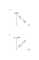
- the figure which shows the relationship of (B), The figure which shows the relationship between the 2nd predetermined period to be set, an engine speed, and water temperature.
- the control device 10 is applied to the engine system 1 and can control each unit constituting the engine system 1.
- the engine system 1 includes an engine 20 as an internal combustion engine, an ignition device 11 and the like.
- the engine 20 is, for example, a premixed combustion type four-cylinder engine driven by gasoline as fuel.
- the engine 20 includes a cylinder 21, an engine head 22, an intake valve 25, an exhaust valve 26, a piston 27, a crankshaft 29, and the like.
- the cylinder 21 is formed in a cylindrical shape. In the present embodiment, four cylinders 21 are formed in the engine 20.
- the engine head 22 is provided so as to close one end of the cylinder 21.
- the engine head 22 is formed with an intake port 23 and an exhaust port 24 that communicate with the inner space of the cylinder 21.
- the intake valve 25 is provided so as to be able to open and close between the intake port 23 and the inner space of the cylinder 21.
- the exhaust valve 26 is provided so as to be able to open and close between the exhaust port 24 and the inner space of the cylinder 21.
- the piston 27 is provided inside the cylinder 21 so as to be capable of reciprocating in the axial direction.
- a combustion chamber 28 is formed by the inner wall of the cylinder 21, the engine head 22, and the piston 27.
- the crankshaft 29 is rotatably provided by the reciprocating movement of the piston 27.
- the crankshaft 29 rotates and torque is output from the crankshaft 29.
- Torque output from the crankshaft 29 is transmitted to a vehicle wheel (not shown). Thereby, the vehicle travels.
- An intake pipe 31 is connected to the intake port 23 of the engine head 22.
- An intake passage 32 is formed inside the intake pipe 31.
- One end of the intake passage 32 is open to the atmosphere, and the other end is connected to the intake port 23.
- the throttle valve 2 is provided in the intake passage 32.
- the throttle valve 2 can be opened and closed by being driven to rotate by the actuator 3. That is, the throttle valve 2 can change the amount of intake air supplied to the combustion chamber 28 by opening and closing the intake passage 32.
- a fuel injection valve 4 is provided near the engine head 22 of the intake pipe 31.
- the fuel injection valve 4 can inject fuel into the intake port 23.
- an air-fuel mixture of fuel and intake air (air) is supplied to the combustion chamber 28.
- the fuel injection valve 4 can change the amount of fuel to be injected by controlling the opening and closing of the injection hole. That is, the fuel injection valve 4 can change the amount of fuel supplied to the combustion chamber 28.
- An exhaust pipe 33 is connected to the exhaust port 24 of the engine head 22.
- An exhaust passage 34 is formed inside the exhaust pipe 33.
- the exhaust passage 34 has one end connected to the exhaust port 24 and the other end open to the atmosphere.
- the air containing the combustion gas generated in the combustion chamber 28 is discharged to the atmosphere side through the exhaust port 24 and the exhaust passage 34.
- the air containing the combustion gas discharged from the combustion chamber 28 of the engine 20 is referred to as exhaust as appropriate.
- a three-way catalyst 35 is provided in the exhaust passage 34. The three-way catalyst 35 purifies the exhaust discharged to the atmosphere side by oxidizing or reducing hydrocarbons, carbon monoxide, and nitrogen oxides in the exhaust.
- the engine system 1 has an EGR pipe 36 that connects the intake pipe 31 and the exhaust pipe 33.
- An EGR passage 37 is formed inside the EGR pipe 36.
- the EGR passage 37 communicates the exhaust passage 34 and the intake passage 32.
- the exhaust in the exhaust passage 34 can be recirculated to the intake passage 32 via the EGR passage 37.
- the EGR valve device 5 is provided in the EGR pipe 36.
- the EGR valve device 5 can open and close the EGR passage 37 by an EGR valve (not shown). That is, the EGR valve device 5 can change the amount of exhaust gas recirculated from the exhaust passage 34 to the intake passage 32 by opening and closing the EGR passage 37.
- the EGR pipe 36 and the EGR valve device 5 constitute an exhaust gas recirculation (EGR) system that supplies exhaust gas discharged from the combustion chamber 28 of the engine 20 to the combustion chamber 28 together with intake air.
- EGR exhaust gas recirculation
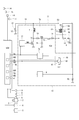
- the ignition device 11 is provided for igniting the air-fuel mixture introduced into the combustion chamber 28. As shown in FIG. 2, the ignition device 11 includes a spark plug 40, an ignition coil 50, an igniter section 60, an energy input section 70, and the like.
- the spark plug 40 has a discharge part 41.
- the discharge part 41 has a center electrode 42 and a ground electrode 43.
- a predetermined gap is formed between the center electrode 42 and the ground electrode 43.
- the spark plug 40 is provided in the engine head 22 so that the discharge part 41 is exposed to the combustion chamber 28 (see FIG. 1).
- the ground electrode 43 is electrically connected to the engine head 22. That is, the ground electrode 43 is grounded.
- the spark plug 40 discharges between the center electrode 42 of the discharge part 41 and the ground electrode 43 by the applied voltage, and can ignite the air-fuel mixture in the combustion chamber 28.
- the ignition coil 50 There are four ignition coils 50 corresponding to each of the four spark plugs 40 (cylinders 21).
- the ignition coil 50 is provided on the engine head 22 so that one end thereof is connected to the side opposite to the discharge part 41 of the spark plug 40 (see FIG. 1).
- the ignition coil 50 has a primary coil 51, a secondary coil 52, a core 53, and a diode 54 (see FIG. 2).
- the primary coil 51 is formed, for example, by winding a copper wire around the core 53 a predetermined number of times, and one end is connected to the positive electrode of the power source 12.
- the power source 12 is a low-voltage battery that can output a voltage of about ten and several volts from the positive electrode, and the negative electrode is grounded (body earth).
- the primary coil 51 is a side on which the other end is grounded.
- the secondary coil 52 is formed by winding a copper wire around the core 53 a predetermined number of times, for example, one end connected to the center electrode 42 of the spark plug 40 and the other end grounded via a diode or the like.
- the number of turns of the secondary coil 52 is set to be larger than that of the primary coil 51.
- the core 53 is made of a material having a magnetic permeability of a predetermined value or more, such as iron.
- the diode 54 is provided on the side opposite to the spark plug 40 with respect to the secondary coil 52.
- the diode 54 is provided such that the anode side is connected to the secondary coil 52 and the cathode side is the ground side. As a result, a current flow from the secondary coil 52 to the ground side via the diode 54 is allowed, and a current flow from the ground side to the secondary coil 52 side via the diode 54 is blocked.
- the igniter section 60 is provided so as to correspond to the four ignition coils 50 (cylinders 21).
- the igniter section 60 is provided on the opposite side of the power supply 12 with respect to the primary coil 51 of the ignition coil 50 (see FIG. 2).
- the igniter unit 60 includes a switching element 61 and a diode 62.
- the switching element 61 is, for example, an IGBT (Insulated Gate Bipolar Transistor).
- the switching element 61 is provided such that the collector is connected to the primary coil 51 and the emitter is grounded.
- the switching element 61 performs a switching operation based on a signal input to the gate so that the switching element 61 is turned on or off.
- the switching element 61 allows a current flow from the primary coil 51 to the ground side via the switching element 61 when in the on state, and from the primary coil 51 to the ground side via the switching element 61 when in the off state. Cut off current flow.
- the diode 62 has an anode connected to the emitter of the switching element 61, that is, grounded.
- the diode 62 is connected to the collector of the switching element 61 on the cathode side, that is, to the primary coil 51. Thereby, the flow of current from the ground side to the primary coil 51 side via the diode 62 is allowed, and the current flow from the primary coil 51 side to the ground side via the diode 62 is blocked.
- the switching element 61 of the igniter unit 60 When the switching element 61 of the igniter unit 60 is in the ON state, the current from the power source 12 flows to the ground side via the primary coil 51 and the switching element 61 of the ignition coil 50. At this time, the core 53 is magnetized to store magnetic energy, and a magnetic field is formed around it. When the current flows through the primary coil 51 and the switching element 61 is turned off, the current flow from the primary coil 51 to the ground side is cut off, the magnetic field around the core 53 changes, and the primary induction occurs due to the self-induction action. A voltage of about several hundred volts is generated in the coil 51. At this time, a high voltage of about several tens of kV is also generated in the secondary coil 52 sharing the magnetic circuit and the magnetic flux.
- the voltage generated in the secondary coil 52 has a magnitude proportional to the number of turns of the primary coil 51 and the secondary coil 52.
- the potential difference between the center electrode 42 of the spark plug 40 and the ground electrode 43 becomes a predetermined value or more.
- dielectric breakdown occurs between the center electrode 42 and the ground electrode 43, and the spark plug 40 discharges between the center electrode 42 and the ground electrode 43.
- the current flowing through the primary coil 51 is referred to as a primary current I1
- the current flowing through the secondary coil 52 is referred to as a secondary current I2
- the voltage of the secondary coil 52 is referred to as a secondary voltage V2.
- the direction from the power supply 12 side to the igniter 60 side is the positive direction of the primary current I1
- the direction from the diode 54 side to the spark plug 40 side is the positive direction of the secondary current I2.
- the secondary voltage V2 when the secondary current I2 in the positive direction flows through the secondary coil 52 is a positive voltage.
- the secondary voltage V2 is a negative voltage, and a negative secondary current I2 flows through the secondary coil 52 during discharge.
- one energy input unit 70 is provided for the four ignition coils 50.
- the energy input unit 70 is provided in parallel with the primary coil 51 between the power supply 12 and the igniter unit 60 (see FIG. 2).
- the energy input unit 70 includes a coil 71, switching elements 72 and 73, diodes 74 and 75, a capacitor 76, and driver circuits 77 and 78.
- the coil 71 is formed, for example, by winding a copper wire a predetermined number of times, and one end thereof is provided so as to be connected between the power source 12 and the primary coil 51.
- the switching elements 72 and 73 are a kind of MOSFET (metal-oxide-semiconductor field-effect transistor) of a field effect transistor.
- the switching element 72 is provided such that the drain is connected to the other end of the coil 71 and the source is grounded.
- the switching element 73 is provided such that its drain is connected between the coil 71 and the switching element 72 and its source is connected between the primary coil 51 and the igniter section 60 of the ignition coil 50.
- four switching elements 73 are provided corresponding to each of the four ignition coils 50 (cylinders 21), but the present invention is not limited to this.
- the switching elements 72 and 73 perform switching operation so as to be turned on or off based on a signal input to the gate.
- the switching element 72 allows a current to flow from the coil 71 to the ground side via the switching element 72.
- the switching element 72 is in the off state, the current flows from the coil 71 to the ground side via the switching element 72. Cut off the flow.
- the switching element 73 is in the on state, the current flow from the coil 71 and the switching element 72 side to the primary coil 51 and the igniter unit 60 side via the switching element 73 is allowed. The flow of current from the element 72 side to the primary coil 51 and the igniter unit 60 side via the switching element 73 is interrupted.
- the diode 74 is provided so that the anode side is connected between the coil 71 and the switching element 72 and the cathode side is connected to the drain of the switching element 73. Thereby, the flow of current from the coil 71 and the switching element 72 side to the switching element 73 side via the diode 74 is allowed, and the current flowing from the switching element 73 side to the coil 71 and switching element 72 side via the diode 74 is allowed. The flow is interrupted.
- the diode 75 is provided so that the anode side is connected to the source of the switching element 73 and the cathode side is connected between the primary coil 51 and the igniter unit 60. Thereby, the flow of current from the switching element 73 side to the primary coil 51 and the igniter section 60 side via the diode 75 is allowed, and from the primary coil 51 and igniter section 60 side to the switching element 73 side via the diode 75. Current flow is interrupted.
- four diodes 75 are provided corresponding to each of the four switching elements 73.
- the capacitor 76 is provided such that one end is connected between the diode 74 and the switching element 73 and the other end is grounded.
- the driver circuit 77 generates a switching signal SWc related to the switching operation of the switching element 72 based on the input signal, and outputs the generated switching signal SWc to the gate of the switching element 72.
- the switching signal SWc is a signal indicating OFF (Lo) or ON (Hi).
- the switching signal SWc is off, the switching element 72 is turned off, and when the switching signal SWc is on, the switching element 72 is turned on.
- the switching element 72 performs a switching operation based on the switching signal SWc input from the driver circuit 77.
- the driver circuit 78 generates a switching signal SWd related to the switching operation of the switching element 73 based on the input signal, and outputs the generated switching signal SWd to the gate of the switching element 73.
- the switching signal SWd is a signal indicating OFF (Lo) or ON (Hi).
- the switching signal SWd is off, the switching element 73 is turned off, and when the switching signal SWd is on, the switching element 73 is turned on.
- the switching element 73 performs a switching operation based on the switching signal SWd input from the driver circuit 78.
- four driver circuits 78 are provided corresponding to each of the four switching elements 73.
- the switching element 73 When the switching element 73 is off and the switching element 72 is on, the current from the power supply 12 flows to the ground side via the coil 71 and the switching element 72. At this time, magnetic energy is stored in the coil 71.
- the current flows through the coil 71, if the switching element 72 is turned off, the current flow from the coil 71 to the ground side is interrupted. As a result, electric energy is released from the coil 71 and supplied to the capacitor 76 via the diode 74.
- the energy input unit 70 can store the electric energy from the power source 12 in the capacitor 76 and can input it to the ignition coil 50.
- the energy input unit 70 ignites so that the secondary current I2 having the same polarity as the secondary current I2 flowing through the secondary coil 52 when the spark plug 40 is discharged, that is, the secondary current I2 in the negative direction is superimposed. Electric energy is input to the coil 50.
- the igniter unit 60 and the energy input unit 70 described above are accommodated in the casing of the ignition circuit unit 13 (see FIG. 2).
- the control device 10 includes a control unit 81, a current detection circuit 91, and the like.
- control unit 81 is housed in a housing of an electronic control unit (hereinafter referred to as “ECU”) 80.
- ECU electronice control unit
- the control unit 81 is, for example, a microcomputer, and includes a CPU as calculation means, a ROM and RAM as storage means, a timer as time measurement means, I / O as input / output means, and the like.
- the control unit 81 performs operations according to a program stored in the ROM based on signals from sensors provided in each part of the vehicle, and controls the operation of devices and devices in each part of the vehicle, thereby integrating the vehicle. Can be controlled.
- a throttle opening sensor 6 is provided in the vicinity of the throttle valve 2 of the intake pipe 31.
- the throttle opening sensor 6 detects the opening of the throttle valve 2 in the intake passage 32 and outputs a signal correlated with the detected opening to the control unit 81.
- the control part 81 can detect the opening degree of the throttle valve 2.
- an air flow meter 7 is provided on the side opposite to the engine 20 with respect to the throttle valve 2 of the intake pipe 31.
- the air flow meter 7 detects the amount of intake air flowing through the intake passage 32, that is, the amount of intake air supplied to the combustion chamber 28 of the engine 20, and outputs a signal correlated to the detected amount of intake air to the control unit 81.
- the control unit 81 can detect the amount of intake air supplied to the combustion chamber 28.
- an intake pressure sensor 8 is provided in a surge tank between the throttle valve 2 of the intake pipe 31 and the engine 20.
- the intake pressure sensor 8 detects the pressure (intake pressure) of the intake air flowing through the intake passage 32 and outputs a signal correlated with the detected pressure to the control unit 81. Thereby, the control unit 81 can detect the intake pressure.
- a cam position sensor 9 is provided in the vicinity of the cam shaft of the engine head 22.
- the cam position sensor 9 detects the rotational position of the camshaft that drives the exhaust valve 26 or the intake valve 25 to open and close, and outputs a signal correlated to the detected rotational position to the control unit 81.
- the control unit 81 can detect the rotational position of the camshaft. Therefore, the control unit 81 can perform cam angle calculation, cylinder discrimination, and the like.
- the engine 20 is provided with a crank position sensor 14 in the vicinity of the crankshaft 29.
- the crank position sensor 14 detects the rotational position of the crankshaft 29 and outputs a signal correlated with the detected rotational position to the control unit 81.
- the control unit 81 can detect the rotational position of the crankshaft 29. Therefore, the control unit 81 can calculate the crank angle and the rotation speed of the crankshaft 29, that is, the rotation speed of the engine 20.
- the engine 20 is provided with a water temperature sensor 15 in the cylinder 21.
- the water temperature sensor 15 detects the temperature (water temperature) of the cooling water that cools the cylinder 21 and outputs a signal correlated to the detected temperature to the control unit 81. Thereby, the control unit 81 can detect the temperature of the cooling water.
- the A / F sensor 16 is provided between the engine 20 of the exhaust pipe 33 and the three-way catalyst 35.
- the A / F sensor 16 detects the air-fuel ratio in the engine 20 from the concentration of oxygen in the exhaust gas flowing through the exhaust passage 34 and the concentration of unburned gas, and outputs a signal correlated with the detected air-fuel ratio to the control unit 81. .
- the control unit 81 can detect the air-fuel ratio in the engine 20.
- An O 2 sensor 17 is provided on the opposite side of the exhaust pipe 33 from the engine 20 with respect to the three-way catalyst 35.
- the air-fuel ratio in the engine 20 is thicker than the stoichiometric air-fuel ratio from the electromotive force generated by the difference between the oxygen concentration in the atmosphere and the oxygen concentration in the exhaust gas flowing through the exhaust passage 34. Whether the state is (rich) or thin (lean) is detected, and a signal (rich signal or lean signal) corresponding to the detected state is output to the control unit 81.
- the control unit 81 can detect whether the air-fuel ratio in the engine 20 is richer or lighter than the stoichiometric air-fuel ratio.
- the power supply 12 is provided with a voltage sensor 18.
- the voltage sensor 18 detects the voltage of the power supply 12 and outputs a signal correlated with the detected voltage to the control unit 81. Thereby, the control unit 81 can detect the voltage of the power supply 12.
- the EGR valve device 5 outputs a signal correlated with the opening degree of the EGR valve in the EGR passage 37 to the control unit 81. Thereby, the control part 81 can detect the opening degree of an EGR valve.
- the control unit 81 operates the ignition device 11 including the ignition plug 40 and the ignition coil 50, the actuator 3 of the throttle valve 2, the fuel injection valve 4, the EGR valve device 5 and the like based on the signals from the various sensors described above. By controlling this, the operation of the engine 20 can be controlled.
- the current detection circuit 91 is accommodated in the casing of the ignition circuit unit 13 (see FIG. 2).
- the ignition circuit unit 13 is provided with a resistor 92.
- the resistor 92 is provided such that one end is connected to the cathode side of the diode 54 of the ignition coil 50 and the other end is grounded.
- the current detection circuit 91 is provided so as to be connected between the diode 54 and the resistor 92. Thereby, the current detection circuit 91 can detect the current flowing from the diode 54 to the ground side, that is, the secondary current I2 flowing through the secondary coil 52.
- the control unit 81 controls the igniter unit 60 so as to cut off the flow of current from the primary coil 51 to the ground side, thereby generating a high voltage in the secondary coil 52 and causing the ignition plug 40 to discharge. Control. Specifically, the control unit 81 controls the spark plug 40 by outputting the ignition signal IGt to the gate of the switching element 61 of the igniter unit 60.
- the ignition signal IGt is a signal indicating off (Lo) or on (Hi).
- the switching element 61 is turned off, and the flow of current (primary current I1) from the primary coil 51 to the ground side via the switching element 61 is interrupted.
- the ignition signal IGt is on, the switching element 61 is turned on, and a current flow from the primary coil 51 to the ground side via the switching element 61 is allowed.
- the ignition signal IGt changes from on to off, the flow of the primary current I1 flowing through the primary coil 51 is interrupted, and a high voltage is generated in the secondary coil 52. As a result, the spark plug 40 discharges between the center electrode 42 and the ground electrode 43 of the discharge part 41. As a result, the mixture in the combustion chamber 28 is ignited (ignited).
- the control unit 81 generates the ignition signal IGt and outputs the ignition signal IGt to the switching element 61 of the igniter unit 60 so that the ignition plug 40 is discharged at the timing when the ignition signal IGt falls from on to off.
- the plug 40 can be controlled.
- the control unit 81 includes a discharge control unit 82 (corresponding to a discharge control unit) that performs the above-described control. Note that the timing at which the ignition signal IGt falls from on to off is defined as the start of control of the spark plug 40 by the discharge control unit 82 (the start of the control period).
- control unit 81 controls the energy input unit 70 so as to input electric energy to the ignition coil 50 after the discharge control unit 82 starts controlling the spark plug 40.
- control unit 81 controls the energy input unit 70 by controlling the switching element 73 by outputting the energy input period signal IGw to the driver circuit 78.
- the energy input period signal IGw is a signal indicating OFF (Lo) or ON (Hi).
- the energy input period signal IGw is generated so as to rise from off to on after the ignition signal IGt falls from on to off, that is, after the discharge control unit 82 starts controlling the spark plug 40.
- the driver circuit 78 outputs the switching signal SWd to the gate of the switching element 73 while the energy input period signal IGw is on. Thereby, the switching element 73 performs a switching operation so that the energy input period signal IGw is in the on state or the off state during the on period.
- the control unit 81 includes an energy input control unit 83 (corresponding to energy input control means) that performs the above-described control.
- the energy input control unit 83 When the energy input control unit 83 is controlled by the energy input control unit 83 and electric energy is input to the ground side of the primary coil 51 of the ignition coil 50, an induced current is generated in the secondary coil 52 of the ignition coil 50.
- This induced current corresponds to electrical energy that can maintain the discharge state of the spark plug 40 generated by the control of the discharge control unit 82. That is, it can be considered that the energy input unit 70 supplies electric energy to the spark plug 40.
- the energy input control unit 83 feeds back the value of the secondary current I2 detected by the current detection circuit 91 so that the current corresponding to the current target value IGa, which is a predetermined current value, is the secondary coil.
- the energy input unit 70 is controlled by controlling the duty ratio of the switching signal SWd (the ratio of the ON period to the switching period) or the like so as to flow through the flow 52.
- the controller 81 stores the electrical energy in the capacitor 76 by controlling the switching element 72 via the driver circuit 77 before the energy input controller 83 inputs the electric energy to the ignition coil 50. .
- the driver circuit 77 outputs the switching signal SWc to the gate of the switching element 72 before the energy input period signal IGw is turned on, for example, during the period when the ignition signal IGt is on.
- the switching element 72 performs a switching operation so as to be in an on state or an off state, for example, while the ignition signal IGt is on.
- electric energy is stored in the capacitor 76.
- the control unit 81 corresponds to a normal ignition control unit 84 (normal ignition control means) that controls ignition of the air-fuel mixture in the combustion chamber 28 only by controlling the spark plug 40 by the discharge control unit 82. )have.
- a normal ignition control unit 84 normal ignition control means
- the electric energy is not input to the ignition coil 50 by the energy input unit 70, so that the discharge of the spark plug 40 is completed in a relatively short time. Therefore, the ignition control of the air-fuel mixture by the normal ignition control unit 84 is suitable for the situation where the air-fuel mixture in the combustion chamber 28 is easily ignited (ignited).
- control unit 81 controls the ignition plug 40 by the discharge control unit 82 and controls the energy input unit 70 by the energy input control unit 83, thereby controlling the ignition of the air-fuel mixture in the combustion chamber 28.
- a control unit 85 (corresponding to specific ignition control means) is included. In the ignition control of the air-fuel mixture by the specific ignition control unit 85, since the electric energy is input to the ignition coil 50 by the energy input unit 70, the discharge of the spark plug 40 lasts for a relatively long time. Therefore, the ignition control of the air-fuel mixture by the specific ignition control unit 85 is suitable for a situation where the air-fuel mixture in the combustion chamber 28 is difficult to be ignited (ignited).
- the control unit 81 for example, when an engine start request is received from a vehicle driver, when an engine start request is received from a device or the like mounted on the vehicle, or engine restart after idling stop is performed.
- the ignition control (energy input control) by the specific ignition control unit 85 is performed until a first predetermined period Tp1 that is a first predetermined period elapses after a start condition that is a condition for starting the engine 20 is satisfied, such as when requested.
- the normal ignition control unit 84 switches to ignition control.
- the energy input control unit 83 performs the second predetermined period Tp2, which is a second predetermined period, after the start of the control of the spark plug 40 by the discharge control unit 82, the ignition coil 50
- the energy input unit 70 is controlled to input electric energy.
- control unit 81 sets the first predetermined period Tp1 and the second predetermined period Tp2 with reference to FIG.
- the control unit 81 For example, based on the temperature of the cooling water (water temperature) detected by the water temperature sensor 15 and the voltage of the power supply 12 (power supply voltage) detected by the voltage sensor 18 when the start condition of the engine 20 is satisfied, the control unit 81 A period Tp1 is set. For example, the controller 81 sets the first predetermined period Tp1 to a longer period as the detected water temperature is lower and the power supply voltage is higher, and sets the first predetermined period Tp1 to a shorter period as the detected water temperature is higher and the power supply voltage is lower. Set (see FIG. 3A).
- the controller 81 calculates the rotation of the engine 20 based on the coolant temperature (water temperature) detected by the water temperature sensor 15 when the start condition of the engine 20 is satisfied and the rotational position of the crankshaft 29 detected by the crank position sensor 14.
- the second predetermined period Tp2 is set based on the number (engine speed). For example, the controller 81 sets the second predetermined period Tp2 to a longer period as the detected water temperature is lower and the calculated engine speed is lower, and the detected water temperature is higher and the calculated engine speed is higher as the calculated engine speed is higher. 2
- the predetermined period Tp2 is set to a short period (see FIG. 3B).
- the control unit 81 sets the first predetermined period Tp1 and the second predetermined period Tp2 as described above, so that the ignition by the specific ignition control unit 85 at the start of the engine is performed as the water temperature is lower and the power supply voltage is higher.
- the driver circuit 77 of the energy input unit 70 When the ignition key is turned on at time t1, the driver circuit 77 of the energy input unit 70 outputs a switching signal SWc that changes to on or off to the switching element 72. Therefore, the switching element 72 performs a switching operation so as to be in an on state or an off state. As a result, electric energy is accumulated in the capacitor 76.
- the driver circuit 77 outputs the switching signal SWc that changes to ON or OFF to the switching element 72 during the period from time t1 to time t3, the voltage Vdc on one end side of the capacitor 76 rises.
- the control unit 81 sets a first predetermined period Tp1 based on the water temperature and the power supply voltage at this time, and a second predetermined time based on the water temperature and the engine speed at this time.
- a period Tp2 is set.
- the control unit 81 sets the timer value Tim to a value corresponding to Tp1.
- the controller 81 subtracts the timer value Tim every unit time.
- the control unit 81 performs ignition control by the specific ignition control unit 85 when the timer value Tim is greater than zero. Therefore, the control unit 81 performs the ignition control by the specific ignition control unit 85 until the timer value Tim becomes 0, that is, until the first predetermined period Tp1 elapses from time t2.
- the control unit 81 determines that energization of the primary coil 51 of the ignition coil 50 should be started at time t4, the ignition signal IGt is turned on. Thereby, energization (primary current I1) to primary coil 51 is started.
- the control unit 81 determines that it is time to ignite the air-fuel mixture at time t5
- the ignition signal IGt is turned off.
- a secondary voltage V2 which is a negative voltage
- the absolute value of the secondary voltage V2 becomes equal to or greater than a predetermined value
- the spark plug 40 is connected to the center electrode 42 and the ground electrode of the discharge part 41. 43 is discharged.
- the mixture in the combustion chamber 28 is ignited (ignited).
- the secondary current I2 in the negative direction flows through the secondary coil 52, and the absolute value of the secondary current I2 becomes a predetermined value or more.
- the absolute value of the secondary voltage V2 quickly becomes equal to or less than a predetermined value.
- the absolute value of the secondary current I2 gradually decreases during the period from time t5 to time t6.
- the driver circuit 78 of the energy input unit 70 When the control unit 81 turns on the energy input period signal IGw at time t6, the driver circuit 78 of the energy input unit 70 outputs the switching signal SWd that changes to on or off to the switching element 73. Thereby, the input of electric energy from the energy input unit 70 to the ignition coil 50 is started.
- the switching element 73 performs a switching operation so that the energy input period signal IGw is in the on state or the off state during the on period (time t6 to time 7, second predetermined period Tp2). Therefore, electric energy is input from the energy input unit 70 to the ignition coil 50 during the period from time t6 to time t7.
- the energy input control unit 83 feeds back the value of the secondary current I2 detected by the current detection circuit 91, so that the current corresponding to the current target value IGa flows through the secondary coil 52.
- the secondary coil 52 has a secondary current I2 (corresponding to the target current value IGa). The average value IGa) flows.
- the control unit 81 determines that energization of the primary coil 51 of the ignition coil 50 should be started at time t8, the ignition signal IGt is turned on. Thereby, energization (primary current I1) to primary coil 51 is started.
- the driver circuit 77 of the energy input unit 70 outputs the switching signal SWc that changes to ON or OFF to the switching element 72 during the period when the ignition signal IGt is ON (time t8 to 9). As a result, electric energy is accumulated in the capacitor 76 during the period of time t8-9.
- the control unit 81 switches to ignition control by the normal ignition control unit 84. Therefore, the control unit 81 performs ignition control by the normal ignition control unit 84 after time t28.
- the control unit 81 determines that energization of the primary coil 51 of the ignition coil 50 should be started at time t29, the ignition signal IGt is turned on. Thereby, energization (primary current I1) to primary coil 51 is started.
- the control unit 81 determines that it is time to ignite the air-fuel mixture at time t30, the ignition signal IGt is turned off.
- the absolute value of the secondary voltage V ⁇ b> 2 that is a voltage generated in the secondary coil 52 becomes a predetermined value or more, and the spark plug 40 is discharged between the center electrode 42 and the ground electrode 43 of the discharge part 41.
- the mixture in the combustion chamber 28 is ignited (ignited).
- the absolute value of the current (secondary current I2) flowing through the secondary coil 52 is equal to or greater than a predetermined value.
- the spark plug 40 is discharged at time t30, the absolute value of the secondary voltage V2 quickly becomes equal to or less than a predetermined value. Further, as the spark plug 40 is discharged, the absolute value of the secondary current I2 gradually decreases after time t30.
- control unit 81 continues the ignition control by the normal ignition control unit 84 until a stop condition that is a condition for stopping the engine 20 is satisfied.
- control unit 81 includes the discharge control unit 82, the energy input control unit 83, the normal ignition control unit 84, and the specific ignition control unit 85.
- the discharge control unit 82 controls the igniter unit 60 to cut off the flow of current from the primary coil 51 to the ground side, thereby generating a high voltage in the secondary coil 52 and causing the spark plug 40 to discharge. To control. Thereby, the spark plug 40 is discharged, and the air-fuel mixture can be ignited.
- the energy input control unit 83 controls the energy input unit 70 to input electric energy to the ignition coil 50 after the discharge control unit 82 starts controlling the spark plug 40. Thereby, the discharge state of the spark plug 40 caused by the control of the discharge control unit 82 can be maintained.
- the normal ignition control unit 84 controls ignition of the air-fuel mixture in the combustion chamber 28 only by controlling the spark plug 40 by the discharge control unit 82.
- the specific ignition control unit 85 controls ignition of the air-fuel mixture in the combustion chamber 28 by controlling the spark plug 40 with the discharge control unit 82 and controlling the energy input unit 70 with the energy input control unit 83.
- ignition control is performed by the specific ignition control unit 85, the discharge state of the spark plug 40 can be maintained by the energy input control unit 83, so that the ignitability of the air-fuel mixture can be improved.
- the control unit 81 performs ignition control by the specific ignition control unit 85 until a first predetermined period Tp1 that is a first predetermined period elapses after a start condition that is a condition for starting the engine 20 is satisfied, and the first predetermined period When the period Tp1 has elapsed, the control is switched to the ignition control by the normal ignition control unit 84. Therefore, the ignitability of the air-fuel mixture can be improved until a predetermined period (first predetermined period Tp1) elapses after the engine 20 is started. Thereby, even when it is difficult to atomize the fuel, such as at a low temperature immediately after the engine 20 is started, the ignitability of the air-fuel mixture can be improved, and misfire and half-burn can be suppressed. Therefore, it is possible to suppress the stop of the engine 20 immediately after the start and the deterioration of the emission.
- the energy input unit 70 inputs electric energy to the ignition coil 50 from the ground side of the primary coil 51.
- the present embodiment shows an example of the configuration of the ignition device 11 (energy input unit 70).
- the ignition device 11 includes one ignition coil 50 for one ignition plug 40.
- the energy input unit 70 continuously supplies electric energy to the ignition coil 50 from the ground side of the primary coil 51, whereby the discharge state generated in the spark plug 40 is changed for a predetermined period (energy input period, second predetermined period Tp2). ), Can be maintained.
- the controller 81 sets the first predetermined period Tp1 based on the temperature of the cooling water of the engine 20 and the voltage of the power source 12. For example, based on the temperature of the cooling water (water temperature) detected by the water temperature sensor 15 and the voltage of the power supply 12 (power supply voltage) detected by the voltage sensor 18 when the start condition of the engine 20 is satisfied, the control unit 81 A period Tp1 is set. For example, the controller 81 sets the first predetermined period Tp1 to a longer period as the detected water temperature is lower and the power supply voltage is higher, and sets the first predetermined period Tp1 to a shorter period as the detected water temperature is higher and the power supply voltage is lower. Set.
- the period of the ignition control (the first predetermined period Tp1) by the specific ignition control unit 85 at the time of starting the engine becomes longer as the water temperature is lower and the power supply voltage is higher. Therefore, even when it is difficult to atomize the fuel, such as at a low temperature immediately after the engine 20 is started, the ignitability of the air-fuel mixture can be improved, and misfire and half-burn can be further suppressed.
- the consumption of electric energy by the energy input unit 70 can be suppressed by shortening the period of the ignition control by the specific ignition control unit 85 (first predetermined period Tp1).
- the energy input control unit 83 starts electric energy to the ignition coil 50 for the second predetermined period Tp2, which is the second predetermined period, after the discharge control unit 82 starts controlling the spark plug 40.
- the energy input unit 70 is controlled to input.
- the discharge state of the spark plug 40 can be changed to a predetermined period (second predetermined period Tp2) even when the air-fuel mixture in the combustion chamber 28 is difficult to ignite (ignite). It is possible to maintain, improve the ignitability of the air-fuel mixture, and further suppress misfire and half-burn.
- the controller 81 sets the second predetermined period Tp2 based on the coolant temperature of the engine 20 and the rotational speed of the engine 20. For example, the controller 81 calculates the rotation of the engine 20 based on the coolant temperature (water temperature) detected by the water temperature sensor 15 when the start condition of the engine 20 is satisfied and the rotational position of the crankshaft 29 detected by the crank position sensor 14.
- the second predetermined period Tp2 is set based on the number (engine speed). For example, the controller 81 sets the second predetermined period Tp2 to a longer period as the detected water temperature is lower and the calculated engine speed is lower, and the detected water temperature is higher and the calculated engine speed is higher as the calculated engine speed is higher.
- the predetermined period Tp2 is set to a short period.
- the lower the water temperature and the lower the engine speed the longer the electric energy input period (second predetermined value Tp2) to the ignition coil 50 by the energy input control unit 83.
- the ignitability of the air-fuel mixture can be improved, and misfire and half-burn can be further suppressed.
- the energy input control unit 83 controls the energy input unit 70 so that a current corresponding to the current target value IGa, which is a predetermined current value, flows through the secondary coil 52.
- the secondary current I2 that substantially corresponds to the current target value IGa flows through the secondary coil 52.
- the discharge state generated in the spark plug 40 can be stably maintained for a predetermined period (energy input period, second predetermined period Tp2).
- the controller 81 determines that the coolant temperature of the engine 20 is predetermined even after the start condition of the engine 20 is satisfied and before the first predetermined period Tp1 has elapsed.
- the ignition control by the specific ignition control unit 85 may be switched to the ignition control by the normal ignition control unit 84.
- the normal ignition control unit does not wait for the elapse of the first predetermined period Tp1.
- the ignition control can be switched to 84. Therefore, excessive consumption of electric energy by the energy input unit 70 can be suppressed.
- the controller 81 determines that the voltage of the power supply 12 is a predetermined value even after the start condition of the engine 20 is satisfied and before the first predetermined period Tp1 has elapsed.
- the ignition control by the specific ignition control unit 85 may be switched to the ignition control by the normal ignition control unit 84.
- the energy input unit 70 is configured to input electric energy from the power source 12 to the ignition coil 50, it is possible to suppress a decrease in the voltage of the power source 12 due to the input of electric energy.
- the control device can be applied to an ignition device capable of maintaining the discharge state of the ignition plug.
- the first predetermined period may be an arbitrary predetermined period regardless of the temperature of the cooling water of the internal combustion engine and the voltage of the power source.
- the second predetermined period may be an arbitrary predetermined period regardless of the temperature of the cooling water of the internal combustion engine and the rotational speed of the internal combustion engine. In this case, for example, the process of setting the first predetermined period and the second predetermined period when the start condition of the internal combustion engine is satisfied can be omitted.
- the energy input control unit 83 feeds back the value of the secondary current I2, so that the current corresponding to the current target value IGa that is a predetermined current value flows through the secondary coil 52.
- throwing-in part 70 was shown.
- the energy input control unit 83 does not feed back the value of the secondary current I2, and the energy input unit so that the current corresponding to the current target value IGa flows through the secondary coil 52. 70 need not be controlled.
- the energy input unit 70 may not include the capacitor 76. Even if the capacitor 76 is not provided, electric energy can be supplied to the ignition coil by appropriately switching the switching elements 72 and 73.
- the energy input unit may be, for example, a part that can input electric energy from a high-voltage power source different from the power source 12 to the ignition coil.
- the number of members constituting the energy input unit can be reduced.
- the switching element 61 of the igniter unit 60 is not limited to the IGBT, and may be constituted by other semiconductor switching elements such as a MOSFET and a transistor. Further, since the MOSFET generally has a parasitic diode, the diode 62 can be omitted when the switching element 61 is configured by a MOSFET.
- the switching elements 72 and 73 of the energy input unit 70 are not limited to MOSFETs, and may be configured by other semiconductor switching elements such as IGBTs and transistors.
- the igniter unit 60 may be provided in the vicinity of the ignition coil 50 without being housed in the casing of the ignition circuit unit 13.
- the current detection circuit 91 may be housed in the casing of the ECU 80.
- the control unit 81 of the ECU 80 may include a current detection circuit 91.
- the control device of the present invention can also be applied to an ignition device for an engine system that does not include an exhaust gas recirculation (EGR) system.
- EGR exhaust gas recirculation
- a negative secondary current flows through the secondary coil of the ignition coil when the spark plug is discharged.
- a secondary current in the positive direction may flow through the secondary coil of the ignition coil when the spark plug is discharged.
- the energy input unit inputs electric energy to the ignition coil so that the secondary current in the negative direction is superimposed is shown.
- the energy input unit may be configured to input electric energy to the ignition coil such that a secondary current in the positive direction is superimposed.
- control device of the present invention is not limited to a four-cylinder internal combustion engine, but can be applied to an ignition device for an internal combustion engine having a number of cylinders other than four.
- the control device of the present invention is not limited to an internal combustion engine having one ignition coil and one ignition plug in each cylinder, but can also be applied to an ignition device for an internal combustion engine having a plurality of ignition coils or ignition plugs in each cylinder. .
- control device of the present invention is not limited to a premixed combustion type internal combustion engine, but can also be applied to an ignition device for a direct injection type internal combustion engine.
- the energy input unit may be anything as long as it can input energy capable of continuing the ignition state.
- the DCO method disclosed in Japanese Patent No. 167665 may be adopted.
- one of the two ignition coils that starts the main discharge is regarded as an ignition coil
- the ignition operation after the main discharge is regarded as an energy input unit
- the coil power source is controlled to control the secondary current.
- the ignition duration time may be controlled.
- Control apparatus 11 Ignition apparatus 12 Power supply 20 Engine (internal combustion engine) 28 Combustion chamber 40 Spark plug 50 Ignition coil 51 Primary coil 52 Secondary coil 60 Igniter section 70 Energy input section 81 Control section 82 Discharge control section (discharge control means) 83 Energy input control unit (energy input control means) 84 Normal ignition control unit (normal ignition control means) 85 Specific ignition control unit (specific ignition control means)
Landscapes
- Engineering & Computer Science (AREA)
- Chemical & Material Sciences (AREA)
- Combustion & Propulsion (AREA)
- Mechanical Engineering (AREA)
- General Engineering & Computer Science (AREA)
- Power Engineering (AREA)
- Theoretical Computer Science (AREA)
- Signal Processing (AREA)
- Ignition Installations For Internal Combustion Engines (AREA)
Abstract
放電制御部は、一次コイルから接地側への電流の流れを遮断するようイグナイタ部を制御することにより二次コイルに高電圧を生じさせ、点火プラグの電極間で放電が形成されるよう点火プラグを制御する。エネルギ投入制御部は、放電制御部による点火プラグの制御開始後、点火コイルに対し電気エネルギを投入するようエネルギ投入部を制御する。通常点火制御部は、放電制御部により点火プラグを制御することのみによって、燃焼室の混合気の点火を制御する。特定点火制御部は、放電制御部により点火プラグを制御し、かつ、エネルギ投入制御部によりエネルギ投入部を制御することによって、燃焼室の混合気の点火を制御する。制御部は、エンジンの始動条件が成立した後、第1所定期間が経過するまで特定点火制御部による点火制御を行い、第1所定期間が経過したとき、通常点火制御部による点火制御に切り替える。
Description
本発明は、制御装置及び制御方法に関し、特に内燃機関の点火装置を制御する制御装置及び制御方法に関する。
従来、内燃機関の点火装置を制御し、燃焼室の混合気の点火を制御する制御装置が知られている。例えば、特許文献1に記載された制御装置では、燃焼室にプラズマを発生させ、混合気の着火性の向上を図っている。
特許文献1の制御装置では、内燃機関の始動時、燃焼室にプラズマを発生させることにより、内燃機関の始動直後の低温時等、燃料の微粒化が困難な場合の失火や半燃えを抑制し、内燃機関の停止およびエミッションの悪化を抑制している。しかしながら、特許文献1の制御装置では、燃焼室にプラズマを発生させるのに所定時間待機する必要がある。そのため、内燃機関の始動が遅れるおそれがある。
本発明は、上述の問題に鑑みてなされたものであり、その目的は、内燃機関始動時の混合気の着火性を向上し、内燃機関を早期に始動させることが可能な制御装置を提供することにある。
本発明は、点火プラグと点火コイルとイグナイタ部とエネルギ投入部とを備える点火装置を制御し、内燃機関の燃焼室の混合気の点火を制御可能な制御装置であって、制御部を備えている。ここで、点火プラグは、内燃機関の燃焼室に設けられ、放電することにより燃焼室の混合気に点火可能である。点火コイルは、一端が電源側に、他端が接地側に接続され一次電流が流れる一次コイル、および、一端が点火プラグに接続され二次電流が流れる二次コイルを有している。イグナイタ部は、一次コイルの接地側に接続され、一次コイルを流れる電流を許容または遮断可能に設けられている。エネルギ投入部は、点火コイルに対し電気エネルギを投入可能である。
制御部は、放電制御手段、エネルギ投入制御手段、通常点火制御手段および特定点火制御手段を有している。
放電制御手段は、一次コイルから接地側への電流の流れを遮断するようイグナイタ部を制御することにより二次コイルに高電圧を生じさせ、点火プラグの電極間で放電が形成されるよう点火プラグを制御する。これにより形成された放電を着火源とし、混合気に点火することができる。
エネルギ投入制御手段は、放電制御手段による点火プラグの制御開始後、点火コイルに対し、二次電流と同じ極性で重畳的に電気エネルギを投入するようエネルギ投入部を制御する。これにより、放電制御手段の制御により生じた点火プラグの放電状態を維持することができる。
通常点火制御手段は、放電制御手段により点火プラグを制御することのみによって、燃焼室の混合気の点火を制御する。
特定点火制御手段は、放電制御手段により点火プラグを制御し、かつ、エネルギ投入制御手段によりエネルギ投入部を制御することによって、燃焼室の混合気の点火を制御する。特定点火制御手段により点火制御を行うとき、エネルギ投入制御手段により点火プラグの放電状態を維持できるため、混合気の着火性を向上することができる。
制御部は、内燃機関の始動の条件である始動条件が成立した後、第1の所定期間である第1所定期間が経過するまでエネルギ投入制御手段によるエネルギ投入を行うことで特定点火制御手段による点火制御を行い、第1所定期間が経過したとき、通常点火制御手段による点火制御に切り替える。そのため、内燃機関が始動してから所定期間(第1所定期間)が経過するまで、混合気の着火性を向上することができる。これにより、内燃機関の始動直後の低温時等、燃料の微粒化が困難な場合であっても、混合気の着火性を向上し、失火や半燃えを抑制することができる。したがって、特に始動直後の内燃機関の停止およびエミッションの悪化を抑制することができる。
また、本発明では、特定点火制御手段による点火制御を行うにあたり、待機時間は必要ない。そのため、内燃機関を早期に始動させることができる。
以下、本発明の実施形態による制御装置を図面に基づき説明する。
本発明の一実施形態による制御装置を図1、2に示す。制御装置10は、エンジンシステム1に適用され、エンジンシステム1を構成する各部を制御可能である。
エンジンシステム1は、内燃機関としてのエンジン20、および、点火装置11等を備えている。
エンジン20は、例えばガソリンを燃料として駆動する予混合燃焼式の4気筒エンジンである。エンジン20は、気筒21、エンジンヘッド22、吸気弁25、排気弁26、ピストン27、クランクシャフト29等を有している。
気筒21は筒状に形成されている。本実施形態では、気筒21は、エンジン20に4つ形成されている。エンジンヘッド22は、気筒21の一端を塞ぐよう設けられている。エンジンヘッド22には、気筒21の内側空間に連通する吸気ポート23および排気ポート24が形成されている。
吸気弁25は、吸気ポート23と気筒21の内側空間との間を開閉可能に設けられている。排気弁26は、排気ポート24と気筒21の内側空間との間を開閉可能に設けられている。
ピストン27は、気筒21の内側で軸方向に往復移動可能に設けられている。気筒21の内壁とエンジンヘッド22とピストン27とにより燃焼室28が形成されている。燃料と空気とが混合した気体、すなわち、混合気が燃焼室28で燃焼すると、燃焼室28の容積が増大しピストン27がエンジンヘッド22とは反対側へ移動する。なお、燃焼室28で混合気が燃焼するとき、燃焼ガスが生じる。
クランクシャフト29は、ピストン27の往復移動により回転可能に設けられている。燃焼室28で燃料が燃焼し、気筒21内でピストン27が往復移動すると、クランクシャフト29が回転し、クランクシャフト29からトルクが出力される。クランクシャフト29から出力されるトルクは、図示しない車両の車輪に伝達される。これにより、車両が走行する。
エンジンヘッド22の吸気ポート23には、吸気管31が接続されている。吸気管31の内側には、吸気通路32が形成されている。吸気通路32は、一端が大気に開放され、他端が吸気ポート23に接続している。これにより、大気(空気)は、吸気通路32および吸気ポート23を経由して燃焼室28に供給される。以下、適宜、大気側からエンジン20の燃焼室28に供給される空気を吸気という。
吸気通路32には、スロットル弁2が設けられている。スロットル弁2は、アクチュエータ3により回転駆動されることで、吸気通路32を開閉可能である。すなわち、スロットル弁2は、吸気通路32を開閉することにより、燃焼室28に供給する吸気の量を変更可能である。
吸気管31のエンジンヘッド22近傍には、燃料噴射弁4が設けられている。燃料噴射弁4は、燃料を吸気ポート23に噴射可能である。これにより、燃料と吸気(空気)との混合気が燃焼室28に供給される。燃料噴射弁4は、噴孔の開閉を制御されることにより、噴射する燃料の量を変更可能である。すなわち、燃料噴射弁4は、燃焼室28に供給する燃料の量を変更可能である。
エンジンヘッド22の排気ポート24には、排気管33が接続されている。排気管33の内側には、排気通路34が形成されている。排気通路34は、一端が排気ポート24に接続し、他端が大気に開放されている。これにより、燃焼室28で生じた燃焼ガスを含む空気は、排気ポート24および排気通路34を経由して大気側に排出される。以下、適宜、エンジン20の燃焼室28から排出される、燃焼ガスを含む空気を排気という。本実施形態では、排気通路34に三元触媒35が設けられている。三元触媒35は、排気中の炭化水素、一酸化炭素および窒素酸化物を酸化または還元することにより、大気側に排出される排気を浄化する。
本実施形態では、エンジンシステム1は、吸気管31と排気管33とを接続するEGR管36を有している。EGR管36の内側には、EGR通路37が形成されている。EGR通路37は、排気通路34と吸気通路32とを連通している。これにより、排気通路34の排気は、EGR通路37を経由して吸気通路32に還流可能である。
EGR管36には、EGR弁装置5が設けられている。EGR弁装置5は、図示しないEGR弁によりEGR通路37を開閉可能である。すなわち、EGR弁装置5は、EGR通路37を開閉することにより、排気通路34から吸気通路32に還流される排気の量を変更可能である。
ここで、EGR管36およびEGR弁装置5は、エンジン20の燃焼室28から排出された排気を吸気とともに燃焼室28に再び供給する排気再循環(EGR:Exhaust Gas Recirculation)システムを構成している。排気を吸気とともに燃焼室28に再び供給することにより、大気に排出される排気中の窒素酸化物の低減、および、燃費の向上等を図ることができる。
点火装置11は、燃焼室28に導入された混合気に点火するために設けられている。図2に示すように、点火装置11は、点火プラグ40、点火コイル50、イグナイタ部60、エネルギ投入部70等を備えている。
点火プラグ40は、4つの気筒21のそれぞれに対応するよう4つ設けられている。点火プラグ40は、放電部41を有している。放電部41は、中心電極42および接地電極43を有している。中心電極42と接地電極43とは、間に所定のギャップを形成している。点火プラグ40は、放電部41が燃焼室28に露出するようエンジンヘッド22に設けられている(図1参照)。接地電極43は、エンジンヘッド22に電気的に接続されている。すなわち、接地電極43は接地されている。点火プラグ40は、印加される電圧により放電部41の中心電極42と接地電極43との間で放電し、燃焼室28の混合気に点火可能である。
点火コイル50は、4つの点火プラグ40(気筒21)のそれぞれに対応するよう4つ設けられている。点火コイル50は、一端が点火プラグ40の放電部41とは反対側に接続するようエンジンヘッド22に設けられている(図1参照)。点火コイル50は、一次コイル51、二次コイル52、コア53およびダイオード54を有している(図2参照)。
一次コイル51は、例えば銅線をコア53に所定回数巻くことにより形成され、一端が電源12の正極に接続されている。電源12は、正極から十数V程度の電圧を出力可能な低圧バッテリであり、負極が接地(ボディアース)されている。一次コイル51は、他端が接地される側である。
二次コイル52は、例えば銅線をコア53に所定回数巻くことにより形成され、一端が点火プラグ40の中心電極42に接続され、他端がダイオードなどを介して接地されている。ここで、二次コイル52の巻回数は、一次コイル51よりも多くなるよう設定されている。
コア53は、例えば鉄等、透磁率が所定値以上の材料により形成されている。
ダイオード54は、二次コイル52に対し点火プラグ40とは反対側に設けられている。ダイオード54は、アノード側が二次コイル52に接続し、カソード側が接地側となるよう設けられている。これにより、二次コイル52からダイオード54を経由した接地側への電流の流れは許容され、接地側からダイオード54を経由した二次コイル52側への電流の流れは遮断されている。
イグナイタ部60は、4つの点火コイル50(気筒21)のそれぞれに対応するよう4つ設けられている。イグナイタ部60は、点火コイル50の一次コイル51に対し電源12とは反対側に設けられている(図2参照)。イグナイタ部60は、スイッチング素子61およびダイオード62を有している。
スイッチング素子61は、本実施形態では、例えばIGBT(Insulated Gate Bipolar Transistor:絶縁ゲートバイポーラトランジスタ)である。スイッチング素子61は、コレクタが一次コイル51に接続され、エミッタが接地されるようにして設けられている。スイッチング素子61は、ゲートに入力される信号に基づき、オン状態またはオフ状態になるようスイッチング作動する。スイッチング素子61は、オン状態のとき、一次コイル51からスイッチング素子61を経由した接地側への電流の流れを許容し、オフ状態のとき、一次コイル51からスイッチング素子61を経由した接地側への電流の流れを遮断する。
ダイオード62は、アノード側がスイッチング素子61のエミッタに接続、すなわち、接地されている。ダイオード62は、カソード側がスイッチング素子61のコレクタに接続、すなわち、一次コイル51に接続されている。これにより、接地側からダイオード62を経由した一次コイル51側への電流の流れは許容され、一次コイル51側からダイオード62を経由した接地側への電流の流れは遮断されている。
イグナイタ部60のスイッチング素子61がオン状態のとき、電源12からの電流は、点火コイル50の一次コイル51およびスイッチング素子61を経由して接地側へ流れる。このとき、コア53は磁化し磁気エネルギが蓄えられ、周囲に磁界が形成される。一次コイル51を電流が流れているとき、スイッチング素子61がオフ状態になると、一次コイル51から接地側への電流の流れが遮断され、コア53の周囲の磁界が変化し、自己誘導作用により一次コイル51に数百V程度の電圧が生じる。このとき、磁気回路および磁束を共有する二次コイル52にも数十kV程度の高電圧が生じる。このとき、二次コイル52に生じる電圧は、一次コイル51と二次コイル52の巻回数に比例した大きさとなる。二次コイル52に高電圧が生じると、点火プラグ40の中心電極42と接地電極43との電位差が所定値以上になる。その結果、中心電極42と接地電極43との間で絶縁破壊が生じ、点火プラグ40は、中心電極42と接地電極43との間で放電する。
以下、適宜、一次コイル51に流れる電流を一次電流I1、二次コイル52に流れる電流を二次電流I2、二次コイル52の電圧を二次電圧V2という。また、電源12側からイグナイタ部60側へ向かう方向を一次電流I1の正方向とし、ダイオード54側から点火プラグ40側へ向かう方向を二次電流I2の正方向とする。また、二次コイル52に正方向の二次電流I2が流れるときの二次電圧V2を正の電圧とする。
本実施形態では、点火プラグ40が放電するとき、二次電圧V2は負の電圧であり、放電時には、二次コイル52に負方向の二次電流I2が流れる。
エネルギ投入部70は、本実施形態では、4つの点火コイル50に対し1つ設けられている。エネルギ投入部70は、電源12とイグナイタ部60との間に一次コイル51と並列に設けられている(図2参照)。エネルギ投入部70は、コイル71、スイッチング素子72、73、ダイオード74、75、コンデンサ76、ドライバ回路77、78を有している。
コイル71は、例えば銅線を所定回数巻くことにより形成され、一端が電源12と一次コイル51との間に接続するよう設けられている。
スイッチング素子72、73は、本実施形態では、電界効果トランジスタの一種のMOSFET(metal-oxide-semiconductor field-effect transistor)である。スイッチング素子72は、ドレインがコイル71の他端に接続され、ソースが接地されるようにして設けられている。スイッチング素子73は、ドレインがコイル71とスイッチング素子72との間に接続し、ソースが点火コイル50の一次コイル51とイグナイタ部60との間に接続するよう設けられている。本実施形態では、スイッチング素子73は、4つの点火コイル50(気筒21)のそれぞれに対応し4つ設けられているが、これに限らない。
スイッチング素子72、73は、ゲートに入力される信号に基づき、オン状態またはオフ状態になるようスイッチング作動する。スイッチング素子72は、オン状態のとき、コイル71からスイッチング素子72を経由した接地側への電流の流れを許容し、オフ状態のとき、コイル71からスイッチング素子72を経由した接地側への電流の流れを遮断する。スイッチング素子73は、オン状態のとき、コイル71およびスイッチング素子72側からスイッチング素子73を経由した一次コイル51およびイグナイタ部60側への電流の流れを許容し、オフ状態のとき、コイル71およびスイッチング素子72側からスイッチング素子73を経由した一次コイル51およびイグナイタ部60側への電流の流れを遮断する。
ダイオード74は、アノード側がコイル71とスイッチング素子72との間に接続し、カソード側がスイッチング素子73のドレインに接続するよう設けられている。これにより、コイル71およびスイッチング素子72側からダイオード74を経由したスイッチング素子73側への電流の流れは許容され、スイッチング素子73側からダイオード74を経由したコイル71およびスイッチング素子72側への電流の流れは遮断されている。
ダイオード75は、アノード側がスイッチング素子73のソースに接続し、カソード側が一次コイル51とイグナイタ部60との間に接続するよう設けられている。これにより、スイッチング素子73側からダイオード75を経由した一次コイル51およびイグナイタ部60側への電流の流れは許容され、一次コイル51およびイグナイタ部60側からダイオード75を経由したスイッチング素子73側への電流の流れは遮断されている。本実施形態では、ダイオード75は、4つのスイッチング素子73のそれぞれに対応し4つ設けられている。
コンデンサ76は、一端がダイオード74とスイッチング素子73との間に接続され、他端が接地されるよう設けられている。
ドライバ回路77は、入力される信号に基づき、スイッチング素子72のスイッチング作動に関するスイッチング信号SWcを生成し、生成したスイッチング信号SWcをスイッチング素子72のゲートに出力する。ここで、スイッチング信号SWcは、オフ(Lo)またはオン(Hi)を示す信号である。スイッチング信号SWcがオフのとき、スイッチング素子72はオフ状態になり、スイッチング信号SWcがオンのとき、スイッチング素子72はオン状態になる。このように、スイッチング素子72は、ドライバ回路77から入力されるスイッチング信号SWcに基づき、スイッチング作動する。
ドライバ回路78は、入力される信号に基づき、スイッチング素子73のスイッチング作動に関するスイッチング信号SWdを生成し、生成したスイッチング信号SWdをスイッチング素子73のゲートに出力する。ここで、スイッチング信号SWdは、オフ(Lo)またはオン(Hi)を示す信号である。スイッチング信号SWdがオフのとき、スイッチング素子73はオフ状態になり、スイッチング信号SWdがオンのとき、スイッチング素子73はオン状態になる。このように、スイッチング素子73は、ドライバ回路78から入力されるスイッチング信号SWdに基づき、スイッチング作動する。本実施形態ではドライバ回路78は、4つのスイッチング素子73のそれぞれに対応し4つ設けられている。
スイッチング素子73がオフ状態でスイッチング素子72がオン状態のとき、電源12からの電流は、コイル71およびスイッチング素子72を経由して接地側へ流れる。このとき、コイル71には磁気エネルギが蓄えられる。コイル71を電流が流れているとき、スイッチング素子72がオフ状態になると、コイル71から接地側への電流の流れが遮断される。これにより、コイル71から電気エネルギが放出され、ダイオード74を経由してコンデンサ76に電気エネルギが供給される。
そのため、スイッチング素子73がオフ状態でスイッチング素子72がオン状態またはオフ状態を交互に繰り返すようスイッチング作動すると、コイル71からコンデンサ76に電気エネルギが徐々に蓄積される。このとき、コンデンサ76の一端側の電圧Vdcは、徐々に高くなる。コンデンサ76に電気エネルギが蓄積された状態、かつ、イグナイタ部60のスイッチング素子61がオフ状態で、スイッチング素子73がオン状態になると、コンデンサ76の電気エネルギがスイッチング素子73およびダイオード75を経由して、対応する点火コイル50の一次コイル51に供給(投入)される。このように、エネルギ投入部70は、電源12からの電気エネルギをコンデンサ76に蓄積し、点火コイル50に対し投入可能である。
本実施形態では、エネルギ投入部70は、点火プラグ40が放電するときに二次コイル52に流れる二次電流I2の極性と同じ、すなわち、負方向の二次電流I2が重畳されるよう、点火コイル50に対し電気エネルギを投入する。
本実施形態では、上述したイグナイタ部60およびエネルギ投入部70は、点火回路ユニット13の筐体に収容されている(図2参照)。
図2に示すように、制御装置10は、制御部81、電流検出回路91等を備えている。
制御部81は、本実施形態では、電子制御ユニット(以下、「ECU」という)80の筐体に収容されている。
制御部81は、例えばマイコンであり、演算手段としてのCPU、記憶手段としてのROM、RAM、時間計測手段としてのタイマ、入出力手段としてのI/O等を有している。制御部81は、車両の各部に設けられたセンサからの信号等に基づき、ROMに格納されたプログラムに従い演算を行い、車両の各部の装置および機器の作動を制御することで、車両を統合的に制御可能である。
図1に示すように、本実施形態では、吸気管31のスロットル弁2の近傍にスロットル開度センサ6が設けられている。スロットル開度センサ6は、吸気通路32におけるスロットル弁2の開度を検出し、検出した開度に相関する信号を制御部81に出力する。これにより、制御部81は、スロットル弁2の開度を検出することができる。
また、吸気管31のスロットル弁2に対しエンジン20とは反対側にエアフローメータ7が設けられている。エアフローメータ7は、吸気通路32を流れる吸気の量、すなわち、エンジン20の燃焼室28に供給される吸気の量を検出し、検出した吸気の量に相関する信号を制御部81に出力する。これにより、制御部81は、燃焼室28に供給される吸気の量を検出することができる。
また、吸気管31のスロットル弁2とエンジン20との間のサージタンクに吸気圧センサ8が設けられている。吸気圧センサ8は、吸気通路32を流れる吸気の圧力(吸気圧)を検出し、検出した圧力に相関する信号を制御部81に出力する。これにより、制御部81は、吸気圧を検出することができる。
また、エンジンヘッド22のカムシャフトの近傍にカムポジションセンサ9が設けられている。カムポジションセンサ9は、排気弁26または吸気弁25を開閉駆動するカムシャフトの回転位置を検出し、検出した回転位置に相関する信号を制御部81に出力する。これにより、制御部81は、カムシャフトの回転位置を検出することができる。そのため、制御部81は、カム角度の算出、および、気筒判別等を行うことができる。
また、エンジン20には、クランクシャフト29の近傍にクランクポジションセンサ14が設けられている。クランクポジションセンサ14は、クランクシャフト29の回転位置を検出し、検出した回転位置に相関する信号を制御部81に出力する。これにより、制御部81は、クランクシャフト29の回転位置を検出することができる。そのため、制御部81は、クランク角の算出、および、クランクシャフト29の回転数、すなわち、エンジン20の回転数の算出等を行うことができる。
また、エンジン20には、気筒21に水温センサ15が設けられている。水温センサ15は、気筒21を冷却する冷却水の温度(水温)を検出し、検出した温度に相関する信号を制御部81に出力する。これにより、制御部81は、冷却水の温度を検出することができる。
また、排気管33のエンジン20と三元触媒35との間にA/Fセンサ16が設けられている。A/Fセンサ16は、排気通路34を流れる排気中の酸素濃度と未燃焼ガス濃度とから、エンジン20内の空燃比を検出し、検出した空燃比に相関する信号を制御部81に出力する。これにより、制御部81は、エンジン20内の空燃比を検出することができる。
また、排気管33の三元触媒35に対しエンジン20とは反対側にO2センサ17が設けられている。O2センサ17は、大気中の酸素濃度と排気通路34を流れる排気中の酸素濃度との差で発生する起電力から、エンジン20内の空燃比が理論空燃比(ストイキオメトリ)に対し濃い(リッチ)状態か薄い(リーン)状態かを検出し、検出した状態に対応する信号(リッチ信号またはリーン信号)を制御部81に出力する。これにより、制御部81は、エンジン20内の空燃比が理論空燃比に対し濃い状態か薄い状態かを検出することができる。
また、電源12には、電圧センサ18が設けられている。電圧センサ18は、電源12の電圧を検出し、検出した電圧に相関する信号を制御部81に出力する。これにより、制御部81は、電源12の電圧を検出することができる。
なお、EGR弁装置5は、EGR通路37におけるEGR弁の開度に相関する信号を制御部81に出力する。これにより、制御部81は、EGR弁の開度を検出することができる。
制御部81は、上述した各種センサからの信号等に基づき、点火プラグ40および点火コイル50を含む点火装置11、スロットル弁2のアクチュエータ3、燃料噴射弁4、および、EGR弁装置5等の作動を制御することで、エンジン20の運転を制御することができる。
電流検出回路91は、本実施形態では、点火回路ユニット13の筐体に収容されている(図2参照)。点火回路ユニット13には、抵抗92が設けられている。抵抗92は、一端が点火コイル50のダイオード54のカソード側に接続し、他端が接地されるよう設けられている。電流検出回路91は、ダイオード54と抵抗92との間に接続するよう設けられている。これにより、電流検出回路91は、ダイオード54から接地側に流れる電流、すなわち、二次コイル52を流れる二次電流I2を検出することができる。
次に、制御部81による点火装置11の制御、および、燃焼室28の混合気の点火制御について説明する。
制御部81は、一次コイル51から接地側への電流の流れを遮断するようイグナイタ部60を制御することにより二次コイル52に高電圧を生じさせ、点火プラグ40が放電するよう点火プラグ40を制御する。具体的には、制御部81は、点火信号IGtをイグナイタ部60のスイッチング素子61のゲートに出力することにより、点火プラグ40を制御する。ここで、点火信号IGtは、オフ(Lo)またはオン(Hi)を示す信号である。点火信号IGtがオフのとき、スイッチング素子61はオフ状態になり、一次コイル51からスイッチング素子61を経由した接地側への電流(一次電流I1)の流れは遮断される。一方、点火信号IGtがオンのとき、スイッチング素子61はオン状態になり、一次コイル51からスイッチング素子61を経由した接地側への電流の流れは許容される。
点火信号IGtがオンからオフに変化すると、一次コイル51を流れていた一次電流I1の流れが遮断され、二次コイル52に高電圧が生じる。これにより、点火プラグ40は、放電部41の中心電極42と接地電極43との間で放電する。その結果、燃焼室28の混合気に火がつく(着火する)。
このように、制御部81は、点火信号IGtを生成しイグナイタ部60のスイッチング素子61に出力することにより、点火信号IGtのオンからオフへの立ち下りのタイミングで点火プラグ40が放電するよう点火プラグ40を制御可能である。本実施形態では、制御部81は、上記の制御を行う放電制御部82(放電制御手段に対応する。)を有する。なお、点火信号IGtがオンからオフに立ち下がるタイミングを、放電制御部82による点火プラグ40の制御開始時(制御期間の始期)とする。
また、制御部81は、放電制御部82による点火プラグ40の制御開始後、点火コイル50に対し電気エネルギを投入するようエネルギ投入部70を制御する。具体的には、制御部81は、エネルギ投入期間信号IGwをドライバ回路78に出力することによりスイッチング素子73を制御することでエネルギ投入部70を制御する。ここで、エネルギ投入期間信号IGwは、オフ(Lo)またはオン(Hi)を示す信号である。エネルギ投入期間信号IGwは、点火信号IGtがオンからオフに立ち下がった後、すなわち、放電制御部82による点火プラグ40の制御開始後、オフからオンに立ち上がるよう生成される。
ドライバ回路78は、エネルギ投入期間信号IGwがオンの期間、スイッチング信号SWdをスイッチング素子73のゲートに出力する。これにより、スイッチング素子73は、エネルギ投入期間信号IGwがオンの期間、オン状態またはオフ状態になるようスイッチング作動する。
スイッチング素子73がオン状態のとき、コンデンサ76に蓄積されていた電気エネルギがスイッチング素子73およびダイオード75を経由して点火コイル50の一次コイル51の接地側に投入される。本実施形態では、制御部81は、上記の制御を行うエネルギ投入制御部83(エネルギ投入制御手段に対応する。)を有する。
エネルギ投入制御部83によりエネルギ投入部70を制御し、点火コイル50の一次コイル51の接地側に電気エネルギを投入すると、点火コイル50の二次コイル52に誘導電流が生じる。この誘導電流は、放電制御部82の制御により生じた点火プラグ40の放電状態を維持可能な電気エネルギに対応する。すなわち、エネルギ投入部70は、点火プラグ40に対し電気エネルギを投入すると考えることもできる。
本実施形態では、エネルギ投入制御部83は、電流検出回路91により検出される二次電流I2の値をフィードバックすることにより、所定の電流値である電流狙い値IGaに対応する電流が二次コイル52を流れるよう、例えばスイッチング信号SWdのデューティー比(スイッチング周期に対するオン期間の割合)等を制御することによりエネルギ投入部70を制御する。これにより、エネルギ投入部70が点火コイル50に電気エネルギを投入する期間、二次コイル52には、概ね電流狙い値IGaに対応する二次電流I2が流れる。
なお、制御部81は、エネルギ投入制御部83により点火コイル50に電気エネルギを投入するのに先立ち、ドライバ回路77を経由してスイッチング素子72を制御することにより、コンデンサ76に電気エネルギを蓄積する。具体的には、ドライバ回路77は、エネルギ投入期間信号IGwがオンになる前の、例えば点火信号IGtがオンの期間等、スイッチング信号SWcをスイッチング素子72のゲートに出力する。これにより、スイッチング素子72は、例えば点火信号IGtがオンの期間、オン状態またはオフ状態になるようスイッチング作動する。その結果、コンデンサ76に電気エネルギが蓄積される。
本実施形態では、制御部81は、放電制御部82により点火プラグ40を制御することのみによって、燃焼室28の混合気の点火を制御する通常点火制御部84(通常点火制御手段に対応する。)を有している。通常点火制御部84による混合気の点火制御では、エネルギ投入部70による点火コイル50に対する電気エネルギの投入は行われないため、点火プラグ40の放電は比較的短時間で終了する。よって、通常点火制御部84による混合気の点火制御は、燃焼室28の混合気に火がつき(着火し)易い状況の場合に適している。
また、制御部81は、放電制御部82により点火プラグ40を制御し、かつ、エネルギ投入制御部83によりエネルギ投入部70を制御することによって、燃焼室28の混合気の点火を制御する特定点火制御部85(特定点火制御手段に対応する。)を有している。特定点火制御部85による混合気の点火制御では、エネルギ投入部70による点火コイル50に対する電気エネルギの投入が行われるため、点火プラグ40の放電は比較的長時間持続する。よって、特定点火制御部85による混合気の点火制御は、燃焼室28の混合気に火がつき(着火し)難い状況の場合に適している。
本実施形態では、制御部81は、例えば、車両の運転者からエンジン始動要求があったとき、車両に搭載された機器等からエンジン始動要求があったとき、または、アイドリングストップ後のエンジン再始動要求があったとき等、エンジン20の始動の条件である始動条件が成立した後、第1の所定期間である第1所定期間Tp1が経過するまで特定点火制御部85による点火制御(エネルギ投入制御を含む)を行い、第1所定期間Tp1が経過したとき、通常点火制御部84による点火制御に切り替える。
また、エネルギ投入制御部83は、特定点火制御部85による点火制御において、放電制御部82による点火プラグ40の制御開始後、第2の所定期間である第2所定期間Tp2、点火コイル50に対し電気エネルギを投入するようエネルギ投入部70を制御する。
次に、制御部81による第1所定期間Tp1および第2所定期間Tp2の設定の仕方について、図3に基づき説明する。
制御部81は、例えばエンジン20の始動条件が成立したとき水温センサ15により検出した冷却水の温度(水温)と電圧センサ18により検出した電源12の電圧(電源電圧)とに基づき、第1所定期間Tp1を設定する。制御部81は、例えば、検出した水温が低く電源電圧が高い場合ほど第1所定期間Tp1を長い期間に設定し、検出した水温が高く電源電圧が低い場合ほど第1所定期間Tp1を短い期間に設定する(図3(A)参照)。
制御部81は、例えばエンジン20の始動条件が成立したとき水温センサ15により検出した冷却水の温度(水温)とクランクポジションセンサ14により検出したクランクシャフト29の回転位置に基づき算出したエンジン20の回転数(エンジン回転数)とに基づき、第2所定期間Tp2を設定する。制御部81は、例えば、検出した水温が低く、算出したエンジン回転数が低い場合ほど第2所定期間Tp2を長い期間に設定し、検出した水温が高く、算出したエンジン回転数が高い場合ほど第2所定期間Tp2を短い期間に設定する(図3(B)参照)。
本実施形態では、上述のように制御部81が第1所定期間Tp1および第2所定期間Tp2を設定することにより、水温が低く電源電圧が高い場合ほどエンジン始動時の特定点火制御部85による点火制御の期間(第1所定期間Tp1)が長くなり、水温が低くエンジン回転数が低い場合ほどエネルギ投入制御部83による点火コイル50に対する電気エネルギの投入期間(第2所定値Tp2、エネルギ投入期間信号IGwのオン期間)が長くなる。
次に、制御装置10、および、制御装置10により制御される点火装置11の作動例を
図4に基づき説明する。
図4に基づき説明する。
時刻t1でイグニッションキーがオンされると、エネルギ投入部70のドライバ回路77は、オンまたはオフに変化するスイッチング信号SWcをスイッチング素子72に出力する。そのため、スイッチング素子72は、オン状態またはオフ状態になるようスイッチング作動する。これにより、コンデンサ76に電気エネルギが蓄積される。ドライバ回路77が時刻t1~3の期間、オンまたはオフに変化するスイッチング信号SWcをスイッチング素子72に出力すると、コンデンサ76の一端側の電圧Vdcは、上昇する。
時刻t2でエンジン20の始動条件が成立すると、制御部81は、このときの水温と電源電圧とに基づき第1所定期間Tp1を設定し、このときの水温とエンジン回転数とに基づき第2所定期間Tp2を設定する。具体的には、制御部81は、タイマ値Timを、Tp1に対応する値にセットする。時刻t2以降、制御部81は、タイマ値Timの値を単位時間毎に減算する。なお、制御部81は、タイマ値Timが0より大きい場合、特定点火制御部85による点火制御を行う。よって、制御部81は、タイマ値Timが0になるまで、すなわち、時刻t2から第1所定期間Tp1が経過するまで、特定点火制御部85による点火制御を行う。
時刻t4で制御部81が点火コイル50の一次コイル51への通電を開始すべきと判断すると、点火信号IGtがオンになる。これにより、一次コイル51への通電(一次電流I1)が開始される。
時刻t5で制御部81が混合気に点火すべきタイミングであると判断すると、点火信号IGtがオフになる。これにより、二次コイル52には負の電圧である二次電圧V2が生じ、二次電圧V2の絶対値が所定値以上になり、点火プラグ40は、放電部41の中心電極42と接地電極43との間で放電する。これにより、燃焼室28の混合気に火がつく(着火する)。このとき、二次コイル52には負方向の二次電流I2が流れ、二次電流I2の絶対値は、所定値以上になる。なお、時刻t5で点火プラグ40が放電すると、これに伴い、二次電圧V2の絶対値は、速やかに所定値以下になる。また、点火プラグ40の放電に伴い、時刻t5~6の期間、二次電流I2の絶対値は、徐々に小さくなる。
時刻t6で制御部81がエネルギ投入期間信号IGwをオンにすると、エネルギ投入部70のドライバ回路78は、オンまたはオフに変化するスイッチング信号SWdをスイッチング素子73に出力する。これにより、エネルギ投入部70から点火コイル50に対する電気エネルギの投入が開始される。スイッチング素子73は、エネルギ投入期間信号IGwがオンの期間(時刻t6~7、第2所定期間Tp2)、オン状態またはオフ状態になるようスイッチング作動する。そのため、時刻t6~7の期間、エネルギ投入部70から点火コイル50に対し電気エネルギが投入される。これにより、点火プラグ40が放電するときに二次コイル52に流れる二次電流I2の極性と同じ、すなわち、負方向の二次電流I2が重畳される。その結果、時刻t5で生じた点火プラグ40の放電状態が維持される。なお、このとき(時刻t6~7)、コンデンサ76の一端側の電圧Vdcは、低下する。
時刻t7で点火コイル50に対する電気エネルギの投入が停止すると、点火プラグ40の放電が停止する(放電状態が解消する)。
本実施形態では、エネルギ投入制御部83が、電流検出回路91により検出される二次電流I2の値をフィードバックすることにより、電流狙い値IGaに対応する電流が二次コイル52を流れるようエネルギ投入部70を制御するため、図4に示すように、エネルギ投入期間信号IGwがオンの期間(時刻t6~7)、二次コイル52には、概ね電流狙い値IGaに対応する二次電流I2(平均値がIGa)が流れる。
時刻t8で制御部81が点火コイル50の一次コイル51への通電を開始すべきと判断すると、点火信号IGtがオンになる。これにより、一次コイル51への通電(一次電流I1)が開始される。また、エネルギ投入部70のドライバ回路77は、点火信号IGtがオンの期間(時刻t8~9)、オンまたはオフに変化するスイッチング信号SWcをスイッチング素子72に出力する。これにより、時刻t8~9の期間、コンデンサ76に電気エネルギが蓄積される。
時刻t10~11の期間、時刻t14~15の期間、時刻t18~19の期間、時刻t22~23の期間、時刻t26~27の期間の作動は、上述の時刻t6~7の期間の作動と同様のため、説明を省略する。
また、時刻t12~13の期間、時刻t16~17の期間、時刻t20~21の期間、時刻t24~25の期間の作動は、上述の時刻t8~9の作動と同様のため、説明を省略する。
時刻t28でタイマ値Timが0になると、すなわち、エンジン20の始動条件が成立した時刻t2から第1所定期間Tp1が経過すると、制御部81は、通常点火制御部84による点火制御に切り替える。よって、制御部81は、時刻t28以降、通常点火制御部84による点火制御を行う。
時刻t29で制御部81が点火コイル50の一次コイル51への通電を開始すべきと判断すると、点火信号IGtがオンになる。これにより、一次コイル51への通電(一次電流I1)が開始される。
時刻t30で制御部81が混合気に点火すべきタイミングであると判断すると、点火信号IGtがオフになる。これにより、二次コイル52に生じる電圧である二次電圧V2の絶対値が所定値以上になり、点火プラグ40は、放電部41の中心電極42と接地電極43との間で放電する。これにより、燃焼室28の混合気に火がつく(着火する)。このとき、二次コイル52に流れる電流(二次電流I2)の絶対値は、所定値以上になる。なお、時刻t30で点火プラグ40が放電すると、これに伴い、二次電圧V2の絶対値は、速やかに所定値以下になる。また、点火プラグ40の放電に伴い、時刻t30以降、二次電流I2の絶対値は、徐々に小さくなる。
時刻t31、32の作動は、上述した時刻t29、30の作動と同様のため、説明を省略する。
時刻t32以降、制御部81は、エンジン20の停止の条件である停止条件が成立するまで、通常点火制御部84による点火制御を継続する。
以上説明したように、(1)本実施形態では、制御部81は、放電制御部82、エネルギ投入制御部83、通常点火制御部84および特定点火制御部85を有している。
放電制御部82は、一次コイル51から接地側への電流の流れを遮断するようイグナイタ部60を制御することにより二次コイル52に高電圧を生じさせ、点火プラグ40が放電するよう点火プラグ40を制御する。これにより、点火プラグ40が放電し、混合気に点火することができる。
エネルギ投入制御部83は、放電制御部82による点火プラグ40の制御開始後、点火コイル50に対し電気エネルギを投入するようエネルギ投入部70を制御する。これにより、放電制御部82の制御により生じた点火プラグ40の放電状態を維持することができる。
通常点火制御部84は、放電制御部82により点火プラグ40を制御することのみによって、燃焼室28の混合気の点火を制御する。
特定点火制御部85は、放電制御部82により点火プラグ40を制御し、かつ、エネルギ投入制御部83によりエネルギ投入部70を制御することによって、燃焼室28の混合気の点火を制御する。特定点火制御部85により点火制御を行うとき、エネルギ投入制御部83により点火プラグ40の放電状態を維持できるため、混合気の着火性を向上することができる。
制御部81は、エンジン20の始動の条件である始動条件が成立した後、第1の所定期間である第1所定期間Tp1が経過するまで特定点火制御部85による点火制御を行い、第1所定期間Tp1が経過したとき、通常点火制御部84による点火制御に切り替える。そのため、エンジン20が始動してから所定期間(第1所定期間Tp1)が経過するまで、混合気の着火性を向上することができる。これにより、エンジン20の始動直後の低温時等、燃料の微粒化が困難な場合であっても、混合気の着火性を向上し、失火や半燃えを抑制することができる。したがって、特に始動直後のエンジン20の停止およびエミッションの悪化を抑制することができる。
また、本実施形態では、特定点火制御部85による点火制御を行うにあたり、待機時間は必要ない。そのため、エンジン20を早期に始動させることができる。
また、(2)本実施形態では、エネルギ投入部70は、一次コイル51の接地側から点火コイル50に対し電気エネルギを投入する。本実施形態は、点火装置11(エネルギ投入部70)の構成の一例を示すものである。本実施形態では、点火装置11は、1つの点火プラグ40に対し点火コイル50を1つ備えている。エネルギ投入部70が、一次コイル51の接地側から点火コイル50に対し電気エネルギを継続的に投入することにより、点火プラグ40で生じた放電状態を所定期間(エネルギ投入期間、第2所定期間Tp2)、維持することができる。
また、(3)本実施形態では、制御部81は、エンジン20の冷却水の温度と電源12の電圧とに基づき、第1所定期間Tp1を設定する。制御部81は、例えばエンジン20の始動条件が成立したとき水温センサ15により検出した冷却水の温度(水温)と電圧センサ18により検出した電源12の電圧(電源電圧)とに基づき、第1所定期間Tp1を設定する。制御部81は、例えば、検出した水温が低く電源電圧が高い場合ほど第1所定期間Tp1を長い期間に設定し、検出した水温が高く電源電圧が低い場合ほど第1所定期間Tp1を短い期間に設定する。これにより、水温が低く電源電圧が高い場合ほどエンジン始動時の特定点火制御部85による点火制御の期間(第1所定期間Tp1)が長くなる。よって、エンジン20の始動直後の低温時等、燃料の微粒化が困難な場合であっても、混合気の着火性を向上し、失火や半燃えをさらに抑制することができる。
また、電源電圧が低いときは、特定点火制御部85による点火制御の期間(第1所定期間Tp1)を短くすることにより、エネルギ投入部70による電気エネルギの消費を抑えることができる。
また、(4)本実施形態では、エネルギ投入制御部83は、放電制御部82による点火プラグ40の制御開始後、第2の所定期間である第2所定期間Tp2、点火コイル50に対し電気エネルギを投入するようエネルギ投入部70を制御する。第2所定期間Tp2を設定することにより、例えば、燃焼室28の混合気に火がつき(着火し)難い状況であっても、点火プラグ40の放電状態を所定期間(第2所定期間Tp2)維持し、混合気の着火性を向上し、失火や半燃えをさらに抑制することができる。
また、(5)本実施形態では、制御部81は、エンジン20の冷却水の温度とエンジン20の回転数とに基づき、第2所定期間Tp2を設定する。制御部81は、例えばエンジン20の始動条件が成立したとき水温センサ15により検出した冷却水の温度(水温)とクランクポジションセンサ14により検出したクランクシャフト29の回転位置に基づき算出したエンジン20の回転数(エンジン回転数)とに基づき、第2所定期間Tp2を設定する。制御部81は、例えば、検出した水温が低く、算出したエンジン回転数が低い場合ほど第2所定期間Tp2を長い期間に設定し、検出した水温が高く、算出したエンジン回転数が高い場合ほど第2所定期間Tp2を短い期間に設定する。これにより、水温が低くエンジン回転数が低い場合ほどエネルギ投入制御部83による点火コイル50に対する電気エネルギの投入期間(第2所定値Tp2)が長くなる。エンジン20の始動直後の低温時等、燃料の微粒化が困難な場合であっても、混合気の着火性を向上し、失火や半燃えをより一層抑制することができる。
また、(6)本実施形態では、エネルギ投入制御部83は、所定の電流値である電流狙い値IGaに対応する電流が二次コイル52を流れるようエネルギ投入部70を制御する。これにより、エネルギ投入部70が点火コイル50に電気エネルギを投入する期間、二次コイル52には、概ね電流狙い値IGaに対応する二次電流I2が流れる。その結果、点火プラグ40で生じた放電状態を所定期間(エネルギ投入期間、第2所定期間Tp2)、安定して維持することができる。
(他の実施形態)
(7)本発明の他の実施形態では、制御部81は、エンジン20の始動条件が成立した後、第1所定期間Tp1が経過する前であっても、エンジン20の冷却水の温度が所定値以上になった場合、特定点火制御部85による点火制御から通常点火制御部84による点火制御に切り替えることとしてもよい。この場合、第1所定期間Tp1を設定した後で燃焼室28の混合気に火がつき(着火し)易い状況になったとき、第1所定期間Tp1の経過を待つことなく、通常点火制御部84による点火制御に切り替えることができる。よって、エネルギ投入部70による電気エネルギの余分な消費を抑えることができる。
(7)本発明の他の実施形態では、制御部81は、エンジン20の始動条件が成立した後、第1所定期間Tp1が経過する前であっても、エンジン20の冷却水の温度が所定値以上になった場合、特定点火制御部85による点火制御から通常点火制御部84による点火制御に切り替えることとしてもよい。この場合、第1所定期間Tp1を設定した後で燃焼室28の混合気に火がつき(着火し)易い状況になったとき、第1所定期間Tp1の経過を待つことなく、通常点火制御部84による点火制御に切り替えることができる。よって、エネルギ投入部70による電気エネルギの余分な消費を抑えることができる。
また、(8)本発明の他の実施形態では、制御部81は、エンジン20の始動条件が成立した後、第1所定期間Tp1が経過する前であっても、電源12の電圧が所定値以下になった場合、特定点火制御部85による点火制御から通常点火制御部84による点火制御に切り替えることとしてもよい。この場合、電源12の電圧が低いときは、エネルギ投入部70による点火コイル50に対する電気エネルギの投入を停止することができる。よって、例えばエネルギ投入部70が電源12からの電気エネルギを点火コイル50に対し投入する構成の場合、電気エネルギの投入による電源12の電圧の低下を抑制することができる。
また、上述の実施形態では、1つの点火プラグに対し点火コイルを1つ備え、エネルギ投入部が一次コイルの接地側から点火コイルに対し電気エネルギを投入する点火装置に制御装置を適用する例を示した。これに対し、本発明の他の実施形態では、例えば1つの点火プラグに対し点火コイルを複数備え、点火プラグの放電制御後にエネルギ投入部から複数の点火コイルに対し電気エネルギを継続的に投入することにより点火プラグの放電状態を維持可能な点火装置に制御装置を適用することもできる。
また、本発明の他の実施形態では、第1所定期間は、内燃機関の冷却水の温度と電源の電圧とにかかわらず、任意の所定の期間であってもよい。また、第2所定期間は、内燃機関の冷却水の温度と内燃機関の回転数とにかかわらず、任意の所定の期間であってもよい。この場合、例えば内燃機関の始動条件が成立したときに第1所定期間および第2所定期間を設定する処理を省略することができる。
また、上述の実施形態では、エネルギ投入制御部83が、二次電流I2の値をフィードバックすることにより、所定の電流値である電流狙い値IGaに対応する電流が二次コイル52を流れるようエネルギ投入部70を制御する例を示した。これに対し、本発明の他の実施形態では、エネルギ投入制御部83は、二次電流I2の値をフィードバックせず、電流狙い値IGaに対応する電流が二次コイル52を流れるようエネルギ投入部70を制御しなくてもよい。
また、本発明の他の実施形態では、エネルギ投入部70は、コンデンサ76を備えない構成であってもよい。コンデンサ76を備えない構成であっても、スイッチング素子72、73を適宜スイッチング作動させることにより、点火コイルに対し電気エネルギを投入することができる。
また、本発明の他の実施形態では、エネルギ投入部は、例えば、電源12とは別の高圧の電源からの電気エネルギを点火コイルに対し投入可能な部位であってもよい。この場合、上述の実施形態と比べ、エネルギ投入部を構成する部材の点数を削減することができる。
また、本発明の他の実施形態では、イグナイタ部60のスイッチング素子61は、IGBTに限らず、例えばMOSFETやトランジスタ等、他の半導体スイッチング素子により構成してもよい。また、MOSFETは一般に寄生ダイオードを有するため、スイッチング素子61をMOSFETにより構成する場合、ダイオード62を省略することができる。
また、本発明の他の実施形態では、エネルギ投入部70のスイッチング素子72、73は、MOSFETに限らず、例えばIGBTやトランジスタ等、他の半導体スイッチング素子により構成してもよい。
また、上述の実施形態では、イグナイタ部60を点火回路ユニット13の筐体に収容する例を示した。これに対し、本発明の他の実施形態では、イグナイタ部60を、点火回路ユニット13の筐体に収容せず、点火コイル50の近傍に設けることとしてもよい。
また、上述の実施形態では、電流検出回路91を、点火回路ユニット13の筐体に収容する例を示した。これに対し、本発明の他の実施形態では、電流検出回路91を、ECU80の筐体に収容することとしてもよい。また、ECU80の制御部81は、電流検出回路91を含むこととしてもよい。
また、本発明の制御装置は、排気再循環(EGR)システムを備えないエンジンシステムの点火装置に適用することもできる。
また、上述の実施形態では、点火プラグの放電時、点火コイルの二次コイルに負方向の二次電流が流れる例を示した。これに対し、本発明の他の実施形態では、点火プラグの放電時、点火コイルの二次コイルに正方向の二次電流が流れる構成であってもよい。
また、上述の実施形態では、エネルギ投入部が、負方向の二次電流が重畳されるよう点火コイルに対し電気エネルギを投入する例を示した。これに対し、本発明の他の実施形態では、エネルギ投入部は、正方向の二次電流が重畳されるよう点火コイルに対し電気エネルギを投入する構成であってもよい。
また、本発明の制御装置は、4気筒の内燃機関に限らず、気筒数が4以外の内燃機関の点火装置に適用することもできる。
また、本発明の制御装置は、各気筒に点火コイル、点火プラグを1つずつ備える内燃機関に限らず、各気筒に点火コイルまたは点火プラグを複数備える内燃機関の点火装置に適用することもできる。
また、本発明の制御装置は、予混合燃焼式の内燃機関に限らず、直噴式の内燃機関の点火装置に適用することもできる。
また、本発明の他の実施形態では、エネルギ投入部は、点火状態を継続可能なエネルギを投入可能であればどのようなものであってもよく、従来の多重放電方式や、例えば特開2012-167665号公報に開示されたDCO方式としてもよい。例えば、DCO方式を採用する場合、2つの点火コイルのうちの主放電を開始する方を点火コイルとみなし、主放電後の点火動作をエネルギ投入部とみなしてコイル電源を制御して二次電流を制御したり点火継続時間を制御したりすればよい。
このように、本発明は、上記実施形態に限定されるものではなく、その要旨を逸脱しない範囲で種々の形態で実施可能である。
10 制御装置
11 点火装置
12 電源
20 エンジン(内燃機関)
28 燃焼室
40 点火プラグ
50 点火コイル
51 一次コイル
52 二次コイル
60 イグナイタ部
70 エネルギ投入部
81 制御部
82 放電制御部(放電制御手段)
83 エネルギ投入制御部(エネルギ投入制御手段)
84 通常点火制御部(通常点火制御手段)
85 特定点火制御部(特定点火制御手段)
11 点火装置
12 電源
20 エンジン(内燃機関)
28 燃焼室
40 点火プラグ
50 点火コイル
51 一次コイル
52 二次コイル
60 イグナイタ部
70 エネルギ投入部
81 制御部
82 放電制御部(放電制御手段)
83 エネルギ投入制御部(エネルギ投入制御手段)
84 通常点火制御部(通常点火制御手段)
85 特定点火制御部(特定点火制御手段)
Claims (9)
- 内燃機関(20)の燃焼室(28)に設けられ、放電することにより前記燃焼室の混合気に点火可能な点火プラグ(40)と、
一端が電源(12)側に、他端が接地側に接続され一次電流が流れる一次コイル(51)、および、一端が前記点火プラグに接続され二次電流が流れる二次コイル(52)を有する点火コイル(50)と、
前記一次コイルの接地側に接続され、前記一次コイルを流れる一次電流を許容または遮断可能に設けられるイグナイタ部(60)と、
前記点火コイルに対し電気エネルギを投入可能なエネルギ投入部(70)と、を備える点火装置(11)を制御し、前記燃焼室の混合気の点火を制御可能な制御装置(10)であって、
前記一次コイルから接地側への電流の流れを遮断するよう前記イグナイタ部を制御することにより前記二次コイルに高電圧を生じさせ、前記点火プラグの電極間で放電が形成されるよう前記点火プラグを制御する放電制御手段(82)と、
前記放電制御手段による前記点火プラグの制御開始後、前記点火コイルに対し電気エネルギを投入するよう前記エネルギ投入部を制御するエネルギ投入制御手段(83)、
前記放電制御手段により前記点火プラグを制御することのみによって、前記燃焼室の混合気の点火を制御する通常点火制御手段(84)と、
前記放電制御手段により前記点火プラグを制御し、かつ、前記エネルギ投入制御手段により前記二次電流と同じ極性で重畳的にエネルギを投入するように前記エネルギ投入部を制御することによって、前記燃焼室の混合気の点火を制御する特定点火制御手段(85)と、
を有する制御部(81)を備え、
前記制御部は、前記内燃機関の始動の条件である始動条件が成立した後、第1の所定期間である第1所定期間(Tp1)が経過するまで前記エネルギ投入制御手段によるエネルギ投入を行うことで前記特定点火制御手段による点火制御を行い、前記第1所定期間が経過したとき、前記通常点火制御手段による点火制御に切り替えることを特徴とする制御装置。 - 前記エネルギ投入部は、前記一次コイルの接地側から前記点火コイルに対し電気エネルギを投入することを特徴とする請求項1に記載の制御装置。
- 前記制御部は、前記内燃機関の冷却水の温度と前記電源の電圧とに基づき、前記第1所定期間を設定することを特徴とする請求項1または2に記載の制御装置。
- 前記エネルギ投入制御手段は、前記放電制御手段による前記点火プラグの制御開始後、第2の所定期間である第2所定期間(Tp2)が経過するまで、前記点火コイルに対し電気エネルギを投入するよう前記エネルギ投入部を制御することを特徴とする請求項1~3のいずれか一項に記載の制御装置。
- 前記制御部は、前記内燃機関の冷却水の温度と前記内燃機関の回転数とに基づき、前記第2所定期間を設定することを特徴とする請求項4に記載の制御装置。
- 前記エネルギ投入制御手段は、所定の電流値である電流狙い値(IGa)に対応する二次電流が前記二次コイルを流れるよう前記エネルギ投入部を制御することを特徴とする請求項1~5のいずれか一項に記載の制御装置。
- 前記制御部は、前記始動条件が成立した後、前記第1所定期間が経過する前であっても、前記内燃機関の冷却水の温度が所定値以上になった場合、前記特定点火制御手段による点火制御から前記通常点火制御手段による点火制御に切り替えることを特徴とする請求項1~6のいずれか一項に記載の制御装置。
- 前記制御部は、前記始動条件が成立した後、前記第1所定期間が経過する前であっても、前記電源の電圧が所定値以下になった場合、前記特定点火制御手段による点火制御から前記通常点火制御手段による点火制御に切り替えることを特徴とする請求項1~7のいずれか一項に記載の制御装置。
- 内燃機関(20)の燃焼室(28)に設けられ、放電することにより前記燃焼室の混合気に点火可能な点火プラグ(40)と、
一端が電源(12)側に、他端が接地側に接続され一次電流が流れる一次コイル(51)、および、一端が前記点火プラグに接続され二次電流が流れる二次コイル(52)を有する点火コイル(50)と、
前記一次コイルの接地側に接続され、前記一次コイルを流れる一次電流を許容または遮断可能に設けられるイグナイタ部(60)と、
前記点火コイルに対し電気エネルギを投入可能なエネルギ投入部(70)と、を備える点火装置(11)を制御し、前記燃焼室の混合気の点火を制御可能な制御方法であって、
制御部(81)の放電制御手段(82)が、前記一次コイルから接地側への電流の流れを遮断するよう前記イグナイタ部を制御することにより前記二次コイルに高電圧を生じさせ、前記点火プラグの電極間で放電が形成されるよう前記点火プラグを制御し、
前記制御部のエネルギ投入制御手段(83)が、前記放電制御手段による前記点火プラグの制御開始後、前記点火コイルに対し電気エネルギを投入するよう前記エネルギ投入部を制御し、
前記制御部の通常点火制御手段(84)が、前記放電制御手段により前記点火プラグを制御することのみによって、前記燃焼室の混合気の点火を制御し、
前記制御部の特定点火制御手段(85)が、前記放電制御手段により前記点火プラグを制御し、かつ、前記エネルギ投入制御手段により前記二次電流と同じ極性で重畳的にエネルギを投入するように前記エネルギ投入部を制御することによって、前記燃焼室の混合気の点火を制御し、
前記制御部が、前記内燃機関の始動の条件である始動条件が成立した後、第1の所定期間である第1所定期間(Tp1)が経過するまで前記エネルギ投入制御手段によるエネルギ投入を行うことで前記特定点火制御手段による点火制御を行い、前記第1所定期間が経過したとき、前記通常点火制御手段による点火制御に切り替えることを特徴とする制御方法。
Priority Applications (1)
| Application Number | Priority Date | Filing Date | Title |
|---|---|---|---|
| US15/301,577 US9890759B2 (en) | 2014-04-10 | 2015-04-03 | Control apparatus and control method |
Applications Claiming Priority (2)
| Application Number | Priority Date | Filing Date | Title |
|---|---|---|---|
| JP2014-080672 | 2014-04-10 | ||
| JP2014080672A JP6471412B2 (ja) | 2014-04-10 | 2014-04-10 | 制御装置 |
Publications (1)
| Publication Number | Publication Date |
|---|---|
| WO2015156221A1 true WO2015156221A1 (ja) | 2015-10-15 |
Family
ID=54287797
Family Applications (1)
| Application Number | Title | Priority Date | Filing Date |
|---|---|---|---|
| PCT/JP2015/060579 Ceased WO2015156221A1 (ja) | 2014-04-10 | 2015-04-03 | 制御装置及び制御方法 |
Country Status (3)
| Country | Link |
|---|---|
| US (1) | US9890759B2 (ja) |
| JP (1) | JP6471412B2 (ja) |
| WO (1) | WO2015156221A1 (ja) |
Cited By (1)
| Publication number | Priority date | Publication date | Assignee | Title |
|---|---|---|---|---|
| CN113658787A (zh) * | 2021-08-10 | 2021-11-16 | 温州汇众汽车电器有限公司 | 带回馈信号的汽车点火线圈 |
Families Citing this family (4)
| Publication number | Priority date | Publication date | Assignee | Title |
|---|---|---|---|---|
| JP6274056B2 (ja) | 2013-11-28 | 2018-02-07 | 株式会社デンソー | 点火装置 |
| WO2015156371A1 (ja) | 2014-04-10 | 2015-10-15 | 株式会社デンソー | 制御装置及び点火装置 |
| EP3555441A4 (en) * | 2017-03-08 | 2020-08-12 | Kerdea Technologies, Inc. | DETECTION OF FAILED COMBUSTION IGNITION EVENTS IN ENGINES BY COMPARING SIGNALS DERIVED FROM TWO DIFFERENT TYPES OF OXYGEN SENSORS |
| WO2020235219A1 (ja) * | 2019-05-23 | 2020-11-26 | 日立オートモティブシステムズ株式会社 | 内燃機関用制御装置 |
Citations (4)
| Publication number | Priority date | Publication date | Assignee | Title |
|---|---|---|---|---|
| JPH05180133A (ja) * | 1991-10-08 | 1993-07-20 | Nippondenso Co Ltd | 内燃機関の点火制御装置 |
| JPH0626428A (ja) * | 1992-07-09 | 1994-02-01 | Mazda Motor Corp | エンジンの点火装置 |
| JP2000170632A (ja) * | 1998-12-07 | 2000-06-20 | Ngk Spark Plug Co Ltd | 点火装置 |
| JP2008138639A (ja) * | 2006-12-05 | 2008-06-19 | Denso Corp | 内燃機関の点火制御装置 |
Family Cites Families (10)
| Publication number | Priority date | Publication date | Assignee | Title |
|---|---|---|---|---|
| JPS5759059A (en) * | 1980-09-25 | 1982-04-09 | Toyota Motor Corp | Ignition timing control method of internal combustion engine |
| JPH09100772A (ja) * | 1995-10-04 | 1997-04-15 | Denso Corp | 内燃機関の失火検出装置 |
| JP3926476B2 (ja) * | 1998-04-27 | 2007-06-06 | 新電元工業株式会社 | トランジスタ式点火装置 |
| JP4462747B2 (ja) * | 2000-10-31 | 2010-05-12 | 日本特殊陶業株式会社 | 内燃機関用点火装置 |
| DE10062892A1 (de) * | 2000-12-16 | 2002-07-11 | Bosch Gmbh Robert | Zündeinrichtung für Brennkraftmaschinen |
| JP4640282B2 (ja) * | 2006-01-31 | 2011-03-02 | 株式会社デンソー | 内燃機関の点火制御装置 |
| US8584650B2 (en) * | 2007-11-07 | 2013-11-19 | Ford Global Technologies, Llc | Ignition energy control for mixed fuel engine |
| JP2009221850A (ja) * | 2008-03-13 | 2009-10-01 | Denso Corp | イオン電流検出機能付きイグナイタ |
| JP2010101177A (ja) | 2008-10-21 | 2010-05-06 | Daihatsu Motor Co Ltd | 火花点火式内燃機関の燃焼制御方法 |
| EP2479420A3 (en) | 2011-01-24 | 2016-06-29 | Diamond Electric MFG. Co., Ltd. | Internal combustion engine ignition system |
-
2014
- 2014-04-10 JP JP2014080672A patent/JP6471412B2/ja not_active Expired - Fee Related
-
2015
- 2015-04-03 WO PCT/JP2015/060579 patent/WO2015156221A1/ja not_active Ceased
- 2015-04-03 US US15/301,577 patent/US9890759B2/en not_active Expired - Fee Related
Patent Citations (4)
| Publication number | Priority date | Publication date | Assignee | Title |
|---|---|---|---|---|
| JPH05180133A (ja) * | 1991-10-08 | 1993-07-20 | Nippondenso Co Ltd | 内燃機関の点火制御装置 |
| JPH0626428A (ja) * | 1992-07-09 | 1994-02-01 | Mazda Motor Corp | エンジンの点火装置 |
| JP2000170632A (ja) * | 1998-12-07 | 2000-06-20 | Ngk Spark Plug Co Ltd | 点火装置 |
| JP2008138639A (ja) * | 2006-12-05 | 2008-06-19 | Denso Corp | 内燃機関の点火制御装置 |
Cited By (2)
| Publication number | Priority date | Publication date | Assignee | Title |
|---|---|---|---|---|
| CN113658787A (zh) * | 2021-08-10 | 2021-11-16 | 温州汇众汽车电器有限公司 | 带回馈信号的汽车点火线圈 |
| CN113658787B (zh) * | 2021-08-10 | 2023-03-17 | 温州汇众汽车电器有限公司 | 带回馈信号的汽车点火线圈 |
Also Published As
| Publication number | Publication date |
|---|---|
| JP6471412B2 (ja) | 2019-02-20 |
| US20170114766A1 (en) | 2017-04-27 |
| JP2015200269A (ja) | 2015-11-12 |
| US9890759B2 (en) | 2018-02-13 |
Similar Documents
| Publication | Publication Date | Title |
|---|---|---|
| US9771918B2 (en) | Ignition system | |
| WO2015156371A1 (ja) | 制御装置及び点火装置 | |
| JP6269271B2 (ja) | 内燃機関用点火装置 | |
| JP6471412B2 (ja) | 制御装置 | |
| JP2008303841A (ja) | 内燃機関及び内燃機関の制御装置 | |
| WO2015156296A1 (ja) | 点火装置 | |
| US10900459B2 (en) | Ignition control system and ignition control device | |
| KR20200020920A (ko) | 점화 장치 | |
| JP6349895B2 (ja) | 内燃機関用点火装置 | |
| JP6264167B2 (ja) | 制御装置 | |
| JP2015200255A (ja) | 点火制御装置 | |
| JP6563699B2 (ja) | 点火制御装置 | |
| JP6375674B2 (ja) | 制御装置 | |
| JP6297899B2 (ja) | 点火装置 | |
| JP2015200258A (ja) | 点火装置 | |
| JP6269270B2 (ja) | 点火装置 | |
| JP6375177B2 (ja) | 内燃機関用点火コイル | |
| JP6531841B2 (ja) | 点火装置 | |
| JP6331614B2 (ja) | 点火制御装置 | |
| JP6330440B2 (ja) | 点火制御装置 | |
| JP6252324B2 (ja) | 内燃機関の制御装置 | |
| JP2010013982A (ja) | 燃料噴射制御装置 | |
| JP2015200262A (ja) | 内燃機関の制御装置 | |
| JP2016070122A (ja) | 内燃機関の制御装置 |
Legal Events
| Date | Code | Title | Description |
|---|---|---|---|
| 121 | Ep: the epo has been informed by wipo that ep was designated in this application |
Ref document number: 15776524 Country of ref document: EP Kind code of ref document: A1 |
|
| WWE | Wipo information: entry into national phase |
Ref document number: 15301577 Country of ref document: US |
|
| NENP | Non-entry into the national phase |
Ref country code: DE |
|
| 122 | Ep: pct application non-entry in european phase |
Ref document number: 15776524 Country of ref document: EP Kind code of ref document: A1 |