WO2015156208A1 - シリンダボア壁の保温具、内燃機関及び自動車 - Google Patents
シリンダボア壁の保温具、内燃機関及び自動車 Download PDFInfo
- Publication number
- WO2015156208A1 WO2015156208A1 PCT/JP2015/060507 JP2015060507W WO2015156208A1 WO 2015156208 A1 WO2015156208 A1 WO 2015156208A1 JP 2015060507 W JP2015060507 W JP 2015060507W WO 2015156208 A1 WO2015156208 A1 WO 2015156208A1
- Authority
- WO
- WIPO (PCT)
- Prior art keywords
- cylinder
- cylinder bore
- metal base
- flow path
- cooling water
- Prior art date
- Legal status (The legal status is an assumption and is not a legal conclusion. Google has not performed a legal analysis and makes no representation as to the accuracy of the status listed.)
- Ceased
Links
Images











Classifications
-
- F—MECHANICAL ENGINEERING; LIGHTING; HEATING; WEAPONS; BLASTING
- F02—COMBUSTION ENGINES; HOT-GAS OR COMBUSTION-PRODUCT ENGINE PLANTS
- F02F—CYLINDERS, PISTONS OR CASINGS, FOR COMBUSTION ENGINES; ARRANGEMENTS OF SEALINGS IN COMBUSTION ENGINES
- F02F1/00—Cylinders; Cylinder heads
- F02F1/02—Cylinders; Cylinder heads having cooling means
- F02F1/10—Cylinders; Cylinder heads having cooling means for liquid cooling
- F02F1/14—Cylinders with means for directing, guiding or distributing liquid stream
-
- F—MECHANICAL ENGINEERING; LIGHTING; HEATING; WEAPONS; BLASTING
- F01—MACHINES OR ENGINES IN GENERAL; ENGINE PLANTS IN GENERAL; STEAM ENGINES
- F01P—COOLING OF MACHINES OR ENGINES IN GENERAL; COOLING OF INTERNAL-COMBUSTION ENGINES
- F01P3/00—Liquid cooling
- F01P3/02—Arrangements for cooling cylinders or cylinder heads
-
- F—MECHANICAL ENGINEERING; LIGHTING; HEATING; WEAPONS; BLASTING
- F02—COMBUSTION ENGINES; HOT-GAS OR COMBUSTION-PRODUCT ENGINE PLANTS
- F02F—CYLINDERS, PISTONS OR CASINGS, FOR COMBUSTION ENGINES; ARRANGEMENTS OF SEALINGS IN COMBUSTION ENGINES
- F02F1/00—Cylinders; Cylinder heads
- F02F1/02—Cylinders; Cylinder heads having cooling means
- F02F1/10—Cylinders; Cylinder heads having cooling means for liquid cooling
- F02F1/16—Cylinder liners of wet type
-
- F—MECHANICAL ENGINEERING; LIGHTING; HEATING; WEAPONS; BLASTING
- F01—MACHINES OR ENGINES IN GENERAL; ENGINE PLANTS IN GENERAL; STEAM ENGINES
- F01P—COOLING OF MACHINES OR ENGINES IN GENERAL; COOLING OF INTERNAL-COMBUSTION ENGINES
- F01P3/00—Liquid cooling
- F01P3/02—Arrangements for cooling cylinders or cylinder heads
- F01P2003/021—Cooling cylinders
Definitions
- the present invention relates to a heat insulator arranged in contact with a wall surface on the grooved coolant flow path side of a cylinder bore wall of a cylinder block of an internal combustion engine, an internal combustion engine including the same, and an automobile having the internal combustion engine.
- Patent Document 1 discloses a flow that divides a groove-shaped cooling heat medium flow path into a plurality of flow paths by being disposed in a groove-shaped cooling heat medium flow path formed in a cylinder block of an internal combustion engine.
- a channel partition member formed at a height less than a depth of the groove-shaped cooling heat medium flow path, and a bore-side flow path and an anti-bore-side flow path in the groove-shaped cooling heat medium flow path
- a flow path dividing member serving as a wall portion that is divided into a groove portion, a groove portion that is formed from the flow path dividing member toward the opening of the groove-shaped cooling heat medium flow channel, and a leading edge is the groove-shaped cooling heat medium.
- the wall temperature of the cylinder bore wall is not all the same temperature, and there is a temperature difference. Therefore, it is necessary to selectively keep the parts that need to be kept warm.
- the internal combustion engine cooling heat medium flow path partition member disclosed in Cited Document 1 has a problem that all the cylinder bore walls can only be kept warm.
- an object of the present invention is to provide a cylinder bore wall heat insulator that can selectively retain a portion of the cylinder bore wall that needs to be kept warm, and is less likely to be displaced due to vibration or the flow of cooling water.
- the present invention (1) is a heat retaining device that is installed in the middle and lower part of a groove-like cooling water flow path of a cylinder block of an internal combustion engine having cylinder bores, and heats a part of the bore walls of all the cylinder bores.
- the present invention (2) is installed in the middle and lower part of the groove-like cooling water flow path of the cylinder block of the internal combustion engine having four or more cylinder bores, and keeps a part of the bore walls of all the cylinder bores. Is a warmer for A rubber member that contacts two or three cylinder bores of the entire wall surface on the cylinder bore side in the middle and lower part of the grooved cooling water flow path, a metal base member to which the rubber member is fixed, and the metal base An elastic member that is attached to the member and urges the metal base member to press the rubber member toward the wall surface on the cylinder bore side in the lower part of the groove-like cooling water flow path, One or more elastic members are attached to each bore portion of the metal base member; (1) A cylinder bore wall heat insulator characterized by the above.
- the present invention (3) is installed in the middle and lower part of the groove-like cooling water flow path of the cylinder block of the internal combustion engine having three cylinder bores, and keeps a part of the bore walls among the bore walls of all the cylinder bores.
- a warmer A rubber member that comes into contact with the wall surface of two cylinder bores out of all wall surfaces on the cylinder bore side in the middle and lower part of the groove-shaped cooling water flow path, a metal base member to which the rubber member is fixed, and an attachment to the metal base member
- An elastic member that urges the metal base member to press the rubber member toward the wall surface on the cylinder bore side in the middle and lower part of the groove-like cooling water flow path,
- One or more elastic members are attached to each bore portion of the metal base member; (1) A cylinder bore wall heat insulator characterized by the above.
- this invention (4) is installed in the center lower part of the groove-shaped cooling water flow path of the cylinder block of the internal combustion engine which has two or more cylinder bores, and heats the one part bore wall of the bore walls of all the cylinder bores. Is a warmer for A rubber member that contacts the wall surface of one cylinder bore of all the wall surfaces on the cylinder bore side in the middle and lower part of the groove-like cooling water flow path, a metal base member to which the rubber member is fixed, the metal base member, An elastic member that urges the metal base member to press the rubber member toward the wall surface on the cylinder bore side in the middle and lower part of the grooved cooling water flow path, One or more elastic members are attached to each bore portion of the metal base member; (1) A cylinder bore wall heat insulator characterized by the above.
- the present invention (5) provides an internal combustion engine characterized in that any one of the cylinder bore wall heat insulators (1) to (4) is installed.
- the present invention (6) provides an automobile characterized by having the internal combustion engine of (5).
- a warmer for a cylinder bore wall that can selectively keep a portion of the cylinder bore wall that needs to be kept warm and that is less likely to be displaced due to vibration or a flow of cooling water.
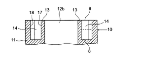
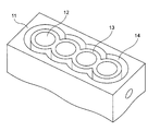
- FIG. 2 is a sectional view taken along line xx of FIG. It is a perspective view of the cylinder block shown in FIG. It is a typical perspective view which shows the form example of the heat insulating tool of the cylinder bore wall of this invention. It is the top view which looked at the heat insulating tool of the cylinder bore wall shown in FIG. 4 from the upper side. It is the side view which looked at the heat insulating tool of the cylinder bore wall shown in FIG. 4 from the rubber member side. It is the side view which looked at the heat insulating tool of the cylinder bore wall shown in FIG.
- FIG. 10 is an end view taken along line xx of FIG. 9. It is a schematic diagram which shows the example of the form of the manufacturing method of the warmer of a cylinder bore wall. It is a schematic diagram which shows the example of the form of the manufacturing method of the warmer of a cylinder bore wall. It is a schematic diagram which shows the example of the form of the manufacturing method of the warmer of a cylinder bore wall. It is a schematic diagram which shows the example of the form of the manufacturing method of the warmer of a cylinder bore wall. It is a schematic diagram which shows the example of the form of the manufacturing method of the warmer of a cylinder bore wall.
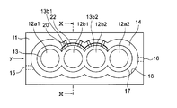
- FIGS. 1 to 3 show an example of a cylinder block in which the cylinder bore wall heat insulator of the present invention is installed
- FIG. 1 shows the cylinder block in which the cylinder bore wall heat insulator of the present invention is installed
- FIG. 2 is a schematic plan view
- FIG. 2 is a sectional view taken along line xx of FIG. 1
- FIG. 3 is a perspective view of the cylinder block shown in FIG. 4 to 7 show an example of the shape of the cylinder bore wall heat insulator of the present invention.
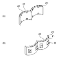
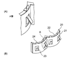
- FIG. 4 is a schematic perspective view showing an example of the shape of the cylinder bore wall heat retainer of the present invention.
- FIG. 4 (A) is a perspective view as seen from the rubber member side
- FIG. 4 (B) is a perspective view as seen from the metal base member side
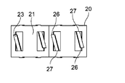
- FIG. 5 shows the heat insulating device for the cylinder bore wall shown in FIG.
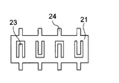
- FIG. 6 is a side view of the cylinder bore wall heat insulator shown in FIG. 4 viewed from the rubber member side
- FIG. 7 is a side view of the cylinder bore wall heat insulator shown in FIG. It is the side view seen from the member side.
- FIG. 8 is a schematic view showing a state in which the cylinder bore wall heat insulator 20 is installed in the cylinder block 11 shown in FIG. 1
- FIG. 9 is a view showing that the cylinder bore wall heat insulator 20 is attached to the cylinder block 11 shown in FIG.
- FIG. 10 is a schematic diagram showing a state of installation
- FIG. 10 is an end view taken along line xx of FIG.
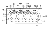
- an open deck type cylinder block 11 of a vehicle-mounted internal combustion engine in which a cylinder bore wall heat insulator is installed is provided with a bore 12 for moving a piston up and down and a cooling water flow.
- the groove-shaped cooling water flow path 14 is formed.
- a wall that separates the bore 12 and the grooved coolant flow path 14 is a cylinder bore wall 13.
- the cylinder block 11 is formed with a cooling water supply port 15 for supplying cooling water to the grooved cooling water flow channel 11 and a cooling water discharge port 16 for discharging cooling water from the grooved cooling water flow channel 11. ing.
- the cylinder block 11 is formed so that two or more bores 12 are arranged in series. Therefore, the bore 12 has end bores 12a1 and 12a2 adjacent to one bore and intermediate bores 12b1 and 12b2 sandwiched between the two bores (note that the number of bores in the cylinder block is two). In the case, only the end bore.) Of the bores arranged in series, the end bores 12a1 and 12a2 are bores at both ends, and the intermediate bores 12b1 and 12b2 are bores between the end bore 12a1 at one end and the end bore 12a2 at the other end.
- the wall surface on the cylinder bore 13 side is described as the wall surface 17 on the cylinder bore side of the grooved cooling water flow path
- a wall surface on the opposite side of the wall surface 17 on the cylinder bore side of the groove-shaped cooling water passage is referred to as a wall surface 18.
- the cylinder bore wall heat insulator 20 shown in FIGS. 4 to 7 includes a metal base member 21, a rubber member 22, and a metal leaf spring member 23.
- the rubber member 22 is formed in a shape in which two arcs are continuous when viewed from above, and the shape on the contact surface 25 side of the rubber member 22 is the middle and lower part of the groove-like cooling water flow path 14 to be kept warm. It is a shape along the wall surface of the cylinder bore side.
- the rubber member 22 is fixed to the metal base member 21 by bending the bent portions 24 formed on the upper side and the lower side of the metal base member 21 and sandwiching the rubber member 22 between the metal base member 21 and the bent portion 24. ing.
- the surface of the rubber member 22 opposite to the metal base member 21 side is a contact surface 25 in contact with the wall surface 17 on the cylinder bore side in the lower part of the grooved cooling water flow path.
- the metal base member 21 is formed in a shape in which two arcs are continuous when viewed from above, and the shape of the metal base member 21 is the back side of the rubber member 22 (on the side opposite to the contact surface 25 side). Surface).
- the rubber member 22 of the cylinder bore wall heat insulator 20 includes a rubber member bore 36a in contact with the wall surface on the intermediate bore 12b1 side and the wall surface on the intermediate bore 12b2 side among the wall surfaces on the bore side in the middle and lower part of the grooved cooling water flow path 14.
- Each bore portion 36b in contact with the rubber member.
- Each bore portion 36a of the rubber member is a portion for keeping the bore wall 13b1 of the intermediate bore 12b1, and each bore portion 36b of the rubber member is a portion for keeping the bore wall 13b2 of the intermediate bore 12b2. is there.
- the metal base member 21 of the heat insulator 20 on the cylinder bore wall includes a metal base member bore 38a to which the rubber member bore 36a is fixed, and a metal base member bore 38b to which the rubber member bore 36b is fixed. It consists of.
- the metal base member 21 is formed of one metal plate. Therefore, the metal base member 21 of the heat insulator 20 on the cylinder bore wall is connected from one end 39a to the other end 39b.
- the metal base member 21 is provided with a metal leaf spring member 23 formed by being integrally formed with the metal base member 21.
- the metal plate spring member 23 is made of metal and is a plate-like elastic body. The metal plate spring member 23 is bent from the metal base member 21 at the other end side 27 connected to the metal base member 21 so that the one end side 26 is separated from the metal base member 21. Is attached.
- the cylinder bore wall heat insulator 20 is installed, for example, in the middle and lower part of the groove-like cooling water flow path 14 of the cylinder block 11 shown in FIG. As shown in FIG. 8, the cylinder bore wall heat insulator 20 is inserted into the grooved coolant flow path 14 of the cylinder block 11, and the cylinder bore wall heat insulator 20 is inserted into the groove shape as shown in FIGS. 9 and 10. Installed in the middle and lower part of the cooling water channel 14.
- the rubber member 22 has a shape along the wall surfaces on the two cylinder bores 12b1 and 12b2 side of the entire wall surface 17 on the cylinder bore side in the middle and lower part of the groove-like cooling water flow path. Therefore, the warmer 20 on the cylinder bore wall is installed in the middle and lower portion of the grooved coolant flow path 14 so that the rubber member 22 contacts the wall surface on the cylinder bores 12b1 and 12b2 side.
- the metal plate is arranged such that the distance from the contact surface 25 of the rubber member 22 to the one end side 26 of the metal plate spring member 23 is larger than the width of the grooved cooling water channel 14.
- a spring member 23 is attached. Therefore, when the heat insulator 20 on the cylinder bore wall is installed in the middle and lower part of the grooved cooling water flow path 14, the metal leaf spring member 23 is sandwiched between the metal base member 21 and the rubber member 22 and the wall surface 18. Thus, a force is applied to the one end side 26 of the metal leaf spring member 23 in the direction toward the metal base member 21.
- the metal plate spring member 23 is deformed so that the one end side 26 approaches the metal base member 21 side, so that an elastic force is generated in the metal plate spring member 23 to return to the original state. Then, due to this elastic force, the metal base member 21 is pushed toward the wall surface 17 on the cylinder bore side of the groove-shaped cooling water flow path. As a result, the metal base member 21 causes the rubber member 22 to move to the groove-shaped cooling water flow path. It is pressed against the wall surface 17 on the cylinder bore side.
- the metal plate spring member 23 is deformed, and the rubber member 22 is moved by the elastic force generated when the deformation is returned.
- the metal base member 21 is urged so as to be pressed against the wall surface 17 on the cylinder bore side of the grooved cooling water flow path.
- the rubber member 22 contacts the wall surface on the bore side of the two cylinder bores 12b1 and 12b2 among the entire wall surface 17 on the cylinder bore side in the middle and lower part of the grooved coolant flow path. .
- the cylinder bore wall heat insulator 20 is manufactured, for example, by the method shown in FIGS. Note that the cylinder bore wall heat insulator of the present invention is not limited to the one manufactured by the method described below.
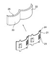
- cut-off portions 31 and 32 indicated by dotted lines are cut off from a rectangular metal plate 30 shown in FIG. 11 to produce a metal base member 21 before forming shown in FIG.
- a bent portion 24 is formed on the upper and lower sides of the metal base member 21, and a metal leaf spring member 23 is formed integrally with the metal base member 21 at the center.
- the metal base member 21 before molding is molded into a shape along the back side of the rubber member 22 (the back side 33 of the rubber member 22 shown in FIG. 14).
- the rubber member 22 formed so that the contact surface 25 side is aligned with the wall surface 17 on the cylinder bore side in the middle and lower part of the grooved cooling water flow path 14 is combined with the metal base member 21 after forming.
- the bent portion 24 is bent toward the rubber member, and the rubber member 22 is sandwiched between the bent portion 24 and the metal base member 21, thereby fixing the rubber member 22 to the metal base member 21. Further, the metal leaf spring member 23 is bent.
- a position before the bent portion 24 and the metal spring member 23 are bent is indicated by a dotted line in a portion A surrounded by a two-dot chain line.
- the cylinder bore wall heat retaining device of the present invention is installed in the middle and lower part of the groove-like cooling water flow path of the cylinder block of the internal combustion engine having the cylinder bore, and is a heat retaining material for heat retaining a part of the bore walls of all the cylinder bores.
- Is a tool A rubber member that contacts a wall surface of one cylinder bore or a wall surface extending over two or more cylinder bores among all wall surfaces on the cylinder bore side in the middle and lower part of the grooved cooling water flow path, and a metal base member to which the rubber member is fixed And an elastic member attached to the metal base member and biasing the metal base member so as to press the rubber member toward the wall surface on the cylinder bore side in the lower part of the grooved cooling water flow path, One or more elastic members are attached to each bore portion of the metal base member; A cylinder bore wall heat insulator characterized by
- the cylinder bore wall heat retainer of the first embodiment of the present invention As the cylinder bore wall heat insulator of the present invention, the cylinder bore wall heat retainer of the first embodiment of the present invention, the cylinder bore wall heat retainer of the second embodiment of the present invention, and the third embodiment of the present invention shown below.
- An example of this is a cylinder bore wall heat insulator.
- the cylinder bore wall heat retaining device (hereinafter also referred to as the cylinder bore wall heat retaining device (1) of the present invention) according to the first aspect of the present invention is a groove cooling of a cylinder block of an internal combustion engine having four or more cylinder bores.
- a cylinder bore wall heat insulator for heat retaining a part of the bore walls of all cylinder bores, A rubber member that contacts two or three cylinder bores of the entire wall surface on the cylinder bore side in the middle and lower part of the grooved cooling water flow path, a metal base member to which the rubber member is fixed, and the metal base
- An elastic member that is attached to the member and urges the metal base member to press the rubber member toward the wall surface on the cylinder bore side in the lower part of the groove-like cooling water flow path,
- One or more elastic members are attached to each bore portion of the metal base member;
- a cylinder bore wall heat insulator characterized by
- the cylinder bore wall heat retaining device (hereinafter also referred to as the cylinder bore wall heat retaining device (2) of the present invention) according to the second embodiment of the present invention is a groove-shaped cooling of a cylinder block of an internal combustion engine having three cylinder bores.
- a cylinder bore wall heat retaining device (hereinafter also referred to as a cylinder bore wall heat retaining device (3) of the present invention) according to a third aspect of the present invention is a groove-like cooling of a cylinder block of an internal combustion engine having two or more cylinder bores.
- a cylinder bore wall heat insulator for heat retaining a part of the bore walls of all cylinder bores, A rubber member that contacts the wall surface of one cylinder bore of all the wall surfaces on the cylinder bore side in the middle and lower part of the groove-like cooling water flow path, a metal base member to which the rubber member is fixed, the metal base member, An elastic member that urges the metal base member to press the rubber member toward the wall surface on the cylinder bore side in the middle and lower part of the grooved cooling water flow path, One or more elastic members are attached to each bore portion of the metal base member; A cylinder bore wall heat insulator characterized by
- the cylinder bore wall heat insulator (1) of the present invention, the cylinder bore wall heat retainer (2) of the present invention, and the cylinder bore wall heat retainer (3) of the present invention are the number of cylinder bores of the cylinder block in which the heat retainer is installed. This is the same except that the number of bore portions of the rubber member is different.
- the cylinder bore wall heat insulator (1), (2) or (3) of the present invention is installed in the lower part of the grooved coolant flow path of the cylinder block of the internal combustion engine.
- the cylinder block on which the cylinder bore wall heat insulating device (1) of the present invention is installed is an open deck type cylinder block in which four or more cylinder bores are arranged in series, so that it has two end bores and two or more end bores.
- the cylinder bore is composed of an intermediate bore.
- the cylinder block in which the cylinder bore wall heat insulator (2) of the present invention is installed is an open deck type cylinder block in which three cylinder bores are arranged in series, so that there are two end bores and one cylinder block. It has a cylinder bore consisting of an intermediate bore.
- the cylinder block in which the cylinder bore wall heat insulator (3) according to the present invention is installed is an open deck type cylinder block in which two or more cylinder bores are arranged in series. Therefore, a cylinder bore composed of two end bores or It has a cylinder bore consisting of two end bores and one or more intermediate bores.
- the bores at both ends are called end bores, and the bores sandwiched between the other cylinder bores are called intermediate bores.
- the position where the heat insulator (1), (2) or (3) on the cylinder bore wall according to the present invention is installed is the middle and lower part of the grooved cooling water flow path.
- a position 10 near the middle between the uppermost part 9 and the lowermost part 8 of the groove-like cooling water flow path 14 is indicated by a dotted line, but the groove-like cooling water flow path 14 on the lower side from the position 10 near the middle is shown.
- This portion is referred to as the middle lower portion of the grooved cooling water flow path.
- the middle and lower part of the grooved cooling water flow path does not mean the part below the middle part between the uppermost part and the lowermost part of the grooved cooling water flow path. It means the part. Therefore, to which position from the lowest part of the grooved cooling water flow path is kept warm by the heat insulator of the present invention, that is, the position of the upper end of the rubber member in the vertical direction of the grooved cooling water flow path, It is selected appropriately.
- the rubber member is a member that keeps the middle and lower part of the cylinder bore wall in contact with the wall surface on the cylinder bore side in the middle and lower part of the grooved coolant flow path. Therefore, the shape on the contact surface side of the rubber member is a shape along the wall surface on the cylinder bore side in the middle and lower part of the grooved cooling water flow path. Then, the cylinder bore wall heat insulator of the present invention is installed in the middle and lower part of the grooved cooling water flow path, so that the elastic member pushes the metal base member, whereby the rubber member The surface side opposite to the member side) is in contact with and pressed against the wall surface on the cylinder bore side in the middle and lower part of the grooved coolant flow path.
- the material of the rubber member examples include solid rubber, expanded rubber, foamed rubber, rubber such as soft rubber, and silicone-based gel material.
- the material of the rubber member when installing the heat insulator of the cylinder bore wall in the grooved cooling water flow path, it is possible to prevent the rubber member from coming into strong contact with the cylinder bore wall and scraping the rubber member.
- the composition of the solid rubber includes natural rubber, butadiene rubber, ethylene propylene diene rubber (EPDM), nitrile butadiene rubber (NBR), silicone rubber, fluorine rubber and the like.
- the expanded rubber examples include heat-sensitive expanded rubber.
- Thermally-expandable rubber is a composite in which a base foam material is impregnated with a thermoplastic material having a melting point lower than that of the base foam material and is compressed. At room temperature, the compressed state is maintained by at least the cured product of the thermoplastic material on the surface layer. In addition, the cured material of the thermoplastic material is softened by heating, and the compressed state is released.
- the heat-sensitive expansion rubber include heat-sensitive expansion rubber described in JP-A-2004-143262.
- the thermal insulation of the cylinder bore wall of the present invention is installed in the lower part of the groove-like cooling water flow path, and heat is applied to the heat-sensitive expansion rubber, so that the heat-sensitive expansion rubber expands. Thus, it expands and deforms into a predetermined shape.
- Examples of the base foam material relating to the heat-expandable rubber include various polymer materials such as rubber, elastomer, thermoplastic resin, and thermosetting resin.
- natural rubber, chloropropylene rubber, styrene butadiene rubber, nitrile Examples include butadiene rubber, ethylene propylene diene terpolymer, various synthetic rubbers such as silicone rubber, fluoro rubber, and acrylic rubber, various elastomers such as soft urethane, various thermosetting resins such as hard urethane, phenol resin, and melamine resin. It is done.
- thermoplastic material related to the heat-expandable rubber those having any of glass transition point, melting point or softening temperature of less than 120 ° C are preferable.
- Thermoplastic materials related to heat-expandable rubber include polyethylene, polypropylene, polystyrene, polyvinyl chloride, polyvinylidene chloride, polyvinyl acetate, polyacrylate ester, styrene butadiene copolymer, chlorinated polyethylene, polyvinylidene fluoride, ethylene acetate Vinyl copolymer, ethylene vinyl acetate vinyl chloride acrylic ester copolymer, ethylene vinyl acetate acrylic ester copolymer, ethylene vinyl acetate vinyl chloride copolymer, nylon, acrylonitrile butadiene copolymer, polyacrylonitrile, polyvinyl chloride , Polychloroprene, polybutadiene, thermoplastic polyimide, polyacetal, polyphenylene sulfide, poly
- examples of the expanded rubber include water-swellable rubber.
- the water-swellable rubber is a material in which a water-absorbing substance is added to rubber, and is a rubber material having a shape retaining property that absorbs water and swells and maintains an expanded shape.
- examples of the water-swellable rubber include a rubber material in which a water-absorbing substance such as a cross-linked product of neutralized polyacrylic acid, a cross-linked product of starch acrylic acid graft copolymer, a cross-linked carboxymethyl cellulose salt, and polyvinyl alcohol is added to the rubber. Can be mentioned.
- water-swellable rubber examples include water-swellable rubbers containing ketiminated polyamide resins, glycidyl etherified products, water-absorbing resins and rubbers described in JP-A-9-208752.
- the material of the rubber member is water-swellable rubber
- the cylinder bore wall heat insulator according to the present invention is installed in the middle and lower part of the groove-like cooling water flow path, the cooling water is flown, and the water-swellable rubber absorbs the water.
- the water-swellable rubber expands and expands and deforms into a predetermined shape.
- the foam rubber is a porous rubber.
- the foam rubber include sponge-like foam rubber having an open cell structure, foam rubber having a closed cell structure, and semi-closed foam rubber.
- Specific examples of the material for the foam rubber include ethylene propylene diene terpolymer, silicone rubber, nitrile butadiene copolymer, silicone rubber, and fluoro rubber.
- the foaming rate of the foamed rubber is not particularly limited and is appropriately selected, and the water content of the rubber member can be adjusted by adjusting the foaming rate.
- the foaming ratio of foamed rubber refers to the density ratio before and after foaming represented by ((density before foaming ⁇ density after foaming) / density before foaming) ⁇ 100.
- the cylinder bore wall heat insulator of the present invention is installed in the groove-shaped cooling water flow path, and the groove-shaped cooling water flow path
- the rubber member contains water.
- the range in which the moisture content of the rubber member is set when the cooling water is caused to flow through the grooved cooling water flow path is appropriately selected depending on the operating conditions of the internal combustion engine.
- a moisture content refers to the weight moisture content represented by (cooling water weight / (filler weight + cooling water weight)) ⁇ 100.
- the thickness of the rubber member is not particularly limited and is appropriately selected.
- Metal base member is a member to which a rubber member is fixed.
- the metal base member is a member that uniformly presses the rubber member against the wall surface on the cylinder bore side in the lower part of the groove-like cooling water flow path by being pressed by the elastic force generated by the deformation of the elastic member. Therefore, the shape of the metal base member is a shape along the back side (surface side opposite to the contact surface) of the rubber member.
- the material of the metal base member is not particularly limited, but stainless steel (SUS), aluminum alloy, and the like are preferable in terms of good long life coolant resistance (hereinafter referred to as “LLC resistance”) and high strength. .
- the thickness of the metal base member is not particularly limited and is appropriately selected.
- the rubber member bends the bent portions formed on the upper and lower sides of the metal base member toward the rubber member, and sandwiches the rubber member between the bent portion and the metal base member.
- the method of fixing the rubber member to the metal base member is not particularly limited.
- Other fixing methods include, for example, a method in which a rubber member is heated and fused to a metal base member, a method in which a rubber member is bonded to a metal base member using an adhesive, and a protrusion is provided on the metal base member. And a method of fitting the rubber member into the rubber member.
- the rubber member is the bore of the cylinder bore.
- the wall surface of the bore wall that extends over the two cylinder bores (that is, the amount that extends over the two cylinder bores)
- the wall surface of the bore wall that extends over the two cylinder bores (that is, the amount that extends over the two cylinder bores)
- the bore wall of three cylinder bores that are in contact with the wall surface on the cylinder bore side of the groove-shaped cooling water flow path) and the middle and lower wall surfaces and in which the heat insulation objects are continuously arranged that is, the bore wall extending over the three cylinder bores
- the rubber member includes three cylinders among all wall surfaces on the grooved cooling water flow path side of the bore wall of the cylinder bore (that is, all wall surfaces on the cylinder bore side of the grooved cooling water flow path).
- Wall surface of minute bore wall over A i.e., the cylinder bore wall surfaces of the minute groove-like cooling water passage over its three cylinder bores
- a portion of the rubber member for keeping the bore wall of one cylinder bore among the bore walls of one, two, or three cylinder bores to be kept warm is referred to as a rubber member bore portion. Therefore, in the cylinder bore wall heat retaining device (1) or (2) of the present invention, when the heat retaining object is the bore wall of two cylinder bores, the rubber member is composed of the two rubber member bore portions, and the heat retaining object is In the case of the bore walls of the three cylinder bores, the rubber member is composed of three rubber member bore portions.
- the position of the cylinder bore wall heat insulator (1) or (2) of the present invention in other words, the wall surface on the cylinder bore side in the middle and lower part of the grooved cooling water flow path where the rubber member contacts is the end bore of one end.
- the rubber member is made up of a wall surface on one end bore side, a wall surface on the other end bore side, and a wall surface on one or more intermediate bore sides. 2 or 3 of them.
- the heat retaining object is the bore wall of one cylinder bore, the entire wall surface (that is, the grooved cooling water flow path side of the bore wall of the cylinder bore on the grooved cooling water flow path side). Of all the wall surfaces on the cylinder bore side, the wall surface of the bore wall of the one cylinder bore (that is, the wall surface on the cylinder bore side of the grooved cooling water flow path of the one cylinder bore) and the wall surface of the middle and lower part.
- the rubber member is composed of one bore portion of one rubber member.
- the heat retaining device (3) for the cylinder bore wall of the present invention is installed, in other words, the wall surface on the cylinder bore side in the middle and lower part of the grooved cooling water flow path where the rubber member contacts, the wall surface on the end bore side of one end, The wall surface on the end bore side of the other end or the wall surface on the intermediate bore side.
- the rubber member contacts one of the wall surfaces on the end bore side at one end, the wall surface on the other end bore side, and the wall surface on the intermediate bore side. Has a site.
- the two rubber member bore portions 36a and 36b are continuous, but the present invention is not limited to this.
- the rubber member corresponds to the bore wall surface of each cylinder bore.
- segmented for every is mentioned.
- rubber attached to each portion corresponding to the bore wall surface of each cylinder bore of the embodiment shown in FIG. An example in which the member is further divided into a plurality of parts is given. As described above, in the warmer (1) or (2) of the cylinder bore wall according to the present invention, all the rubber member bore portions may be continuous or may not be continuous.
- the rubber members may be continuous or may be divided into a plurality of parts.
- the rubber member is a wall surface (heat insulation object) among the wall surfaces on the cylinder bore side in the lower part of the grooved cooling water flow path. All of the one, two, or three cylinder bores on the groove wall surface of the grooved cooling water flow path side) may be covered completely, or may be a part of the wall surface to be kept warm. In addition, it may cover only a portion necessary for heat insulation.
- the metal base member is composed of two or three metal base member bore portions.
- each bore portion of the metal base member refers to a portion to which each bore portion of each rubber member is fixed. Therefore, in the cylinder bore wall heat retaining device (1) or (2) of the present invention, when the heat retaining object is the wall surface on the grooved coolant flow path side of the bore walls of the two cylinder bores, the metal base member is each of the two metal base members. When the heat retaining object is a wall surface on the bore side of the three cylinder bores, the metal base member is composed of the three metal base member bore parts. Each bore portion of the rubber member is fixed to each bore portion of each metal base member.
- the metal base member is connected from one end to the other end. That is, in the metal base member, all the metal base member bore portions are connected.
- the metal base member is formed of one metal plate from one end to the other end.
- the present invention is not limited to this, and the metal base member is formed from one end. As long as the other end is connected, it may be formed of one metal plate or a plurality of metal plates connected together.
- the metal base member is composed of one bore portion of one metal base member.
- the respective bore portions of the rubber member are fixed to the respective bore portions of the metal base member.
- the metal base member is connected from one end to the other end.
- the elastic member is attached to the metal base member.
- This elastic member is elastically deformed by installing the heat insulator of the cylinder bore wall of the present invention in the middle and lower part of the groove-like cooling water flow path, toward the wall surface on the cylinder bore side in the lower part of the groove-like cooling water flow path, It is a member for biasing the metal base member so as to press the rubber member.
- one or more elastic members are provided for each bore portion of the metal base member. That is, when the heat insulator (1), (2) or (3) of the cylinder bore wall according to the present invention is viewed from above, an elastic member is attached to at least one place in the arc direction of each bore portion of each metal base member. ing. And when the number of installation of the elastic members is viewed from the upper side of the cylinder bore wall heat insulator (1), (2) or (3) according to the present invention, for each bore portion of the metal base member, in the arc direction, Two or more are preferable, and three or more are particularly preferable. In the cylinder bore wall heat insulator 20 shown in FIG. 4, two elastic members are attached in the arc direction for each of the bore portions of the metal base member.
- the form of the elastic member is not particularly limited, and examples thereof include a plate-like elastic member, a coil-like elastic member, a laminated leaf spring, a torsion spring, and elastic rubber.
- the material of the elastic member is not particularly limited, but stainless steel (SUS), aluminum alloy, and the like are preferable in terms of good LLC resistance and high strength.
- the elastic member is preferably a metal elastic member such as a metal leaf spring, a coil spring, a laminated leaf spring, or a torsion spring.
- the rubber member is urged by an appropriate pressing force by the elastic member when installed in the middle lower part of the groove-like cooling water flow path.
- the form, shape, size, installation position, number of installations, and the like of the elastic member are appropriately selected in accordance with the shape of the grooved cooling water flow path.
- the elastic member is attached by being integrally formed with the metal base member, but the method of attaching the elastic member to the metal base member is not particularly limited. Examples of other methods include a method of welding a metal elastic member such as a metal plate spring, a metal coil spring, a laminated plate spring, or a torsion spring to the metal base member. In the embodiment shown in FIG. 19, a metal plate spring 53 a made of a vertically long rectangular metal plate is welded to a metal base member 51 without a cut-off portion. As another method, as in the embodiment shown in FIG.
- the metal base member 51 is fixed to the rubber member 22 from the side of the metal base member 51 by making the member 54 and superimposing them on the rubber member 22 and bending the bent portions 55a and 55b.
- the cylinder bore wall heat retaining device (1), (2) or (3) of the present invention is located at the lower part of the grooved coolant flow path, in other words, which of the bore walls of all the cylinder bores. Whether it is used for heat insulation of the bore wall of the cylinder bore is appropriately selected.
- the warmer 20 of the cylinder bore wall is installed in the middle and lower part of the grooved cooling water flow path 14 so that the bore wall 13b1 of the intermediate bore 12b1 and the bore wall 13b2 of the intermediate bore 12b2 are kept warm.
- FIG.17 and FIG.18 is mentioned. In FIG.
- the cylinder bore wall heat insulator 40 is installed in the middle and lower part of the grooved cooling water channel 14 so that the bore wall 13a1 of the end bore 12a1 and the bore wall 13b1 of the intermediate bore 12b1 are kept warm.
- the cylinder bore wall heat insulator 41 is provided in the grooved coolant passage 14 so that the bore wall 13a1 of the end bore 12a1, the bore wall 13b1 of the intermediate bore 12b1, and the bore wall 13b2 of the intermediate bore 12b2 are kept warm. It is installed in the middle and lower part.
- the internal combustion engine of the present invention is an internal combustion engine in which the cylinder bore wall heat insulator (1), (2) or (3) of the present invention is installed in the lower part of the groove-like cooling water flow path. .
- the location where the cylinder bore wall heat retaining device (1), (2) or (3) of the present invention is installed requires heat insulation in the middle and lower part of the grooved cooling water flow path. It is a place. That is, in the internal combustion engine of the present invention, the heat retaining device (1), (2) or (3) of the cylinder bore wall of the present invention is selectively installed at a place where heat insulation is necessary.
- the automobile of the present invention is an automobile having the internal combustion engine of the present invention.
- the cylinder bore wall heat insulator (1), (2) or (3) according to the present invention can selectively heat only a portion requiring heat insulation.
- one or more elastic members are provided for each bore portion of the metal base member, so that the rubber member is a heat retaining object. It is evenly pressed against the wall surface on the cylinder bore side in the middle and lower part of the grooved coolant flow path.
- the metal base member is not divided for each bore part, but is connected to each other. The heat insulator (1) or (2) is less likely to be displaced due to vibration or the flow of cooling water in the grooved cooling water flow path.
- the difference in deformation amount between the upper side and the lower side of the cylinder bore wall of the internal combustion engine can be reduced, and the friction of the piston can be reduced, so that a fuel-saving internal combustion engine can be provided.
Landscapes
- Engineering & Computer Science (AREA)
- Chemical & Material Sciences (AREA)
- Combustion & Propulsion (AREA)
- Mechanical Engineering (AREA)
- General Engineering & Computer Science (AREA)
- Cylinder Crankcases Of Internal Combustion Engines (AREA)
Abstract
Description
溝状冷却水流路の中下部のシリンダボア側の全壁面のうちの1つのシリンダボアの壁面又は2つ以上のシリンダボアに亘る分の壁面に接触するゴム部材と、該ゴム部材が固定される金属基体部材と、該金属基体部材に付設され、該溝状冷却水流路の中下部のシリンダボア側の壁面に向かって、該金属基体部材が該ゴム部材を押し付けるように付勢する弾性部材と、からなり、
該弾性部材が、該金属基体部材の各ボア部毎に、1つ以上付設されていること、
を特徴するシリンダボア壁の保温具を提供するものである。
溝状冷却水流路の中下部のシリンダボア側の全壁面のうちの2つ又は3つのシリンダボアに亘る分の壁面に接触するゴム部材と、該ゴム部材が固定される金属基体部材と、該金属基体部材に付設され、該溝状冷却水流路の中下部のシリンダボア側の壁面に向かって、該金属基体部材が該ゴム部材を押し付けるように付勢する弾性部材と、からなり、
該弾性部材が、該金属基体部材の各ボア部毎に、1つ以上付設されていること、
を特徴する(1)のシリンダボア壁の保温具を提供するものである。
溝状冷却水流路の中下部のシリンダボア側の全壁面のうちの2つのシリンダボアに亘る分の壁面に接触するゴム部材と、該ゴム部材が固定される金属基体部材と、該金属基体部材に付設され、該溝状冷却水流路の中下部のシリンダボア側の壁面に向かって、該金属基体部材が該ゴム部材を押し付けるように付勢する弾性部材と、からなり、
該弾性部材が、該金属基体部材の各ボア部毎に、1つ以上付設されていること、
を特徴する(1)のシリンダボア壁の保温具を提供するものである。
溝状冷却水流路の中下部のシリンダボア側の全壁面のうちの1つのシリンダボアの壁面に接触するゴム部材と、該ゴム部材が固定される金属基体部材と、該金属基体部材に付設され、該溝状冷却水流路の中下部のシリンダボア側の壁面に向かって、該金属基体部材が該ゴム部材を押し付けるように付勢する弾性部材と、からなり、
該弾性部材が、該金属基体部材の各ボア部毎に、1つ以上付設されていること、
を特徴する(1)のシリンダボア壁の保温具を提供するものである。
溝状冷却水流路の中下部のシリンダボア側の全壁面のうちの1つのシリンダボアの壁面又は2つ以上のシリンダボアに亘る分の壁面に接触するゴム部材と、該ゴム部材が固定される金属基体部材と、該金属基体部材に付設され、該溝状冷却水流路の中下部のシリンダボア側の壁面に向かって、該金属基体部材が該ゴム部材を押し付けるように付勢する弾性部材と、からなり、
該弾性部材が、該金属基体部材の各ボア部毎に、1つ以上付設されていること、
を特徴するシリンダボア壁の保温具である。
溝状冷却水流路の中下部のシリンダボア側の全壁面のうちの2つ又は3つのシリンダボアに亘る分の壁面に接触するゴム部材と、該ゴム部材が固定される金属基体部材と、該金属基体部材に付設され、該溝状冷却水流路の中下部のシリンダボア側の壁面に向かって、該金属基体部材が該ゴム部材を押し付けるように付勢する弾性部材と、からなり、
該弾性部材が、該金属基体部材の各ボア部毎に、1つ以上付設されていること、
を特徴するシリンダボア壁の保温具である。
溝状冷却水流路の中下部のシリンダボア側の全壁面のうちの2つのシリンダボアに亘る分の壁面に接触するゴム部材と、該ゴム部材が固定される金属基体部材と、該金属基体部材に付設され、該溝状冷却水流路の中下部のシリンダボア側の壁面に向かって、該金属基体部材が該ゴム部材を押し付けるように付勢する弾性部材と、からなり、
該弾性部材が、該金属基体部材の各ボア部毎に、1つ以上付設されていること、
を特徴するシリンダボア壁の保温具である。
溝状冷却水流路の中下部のシリンダボア側の全壁面のうちの1つのシリンダボアの壁面に接触するゴム部材と、該ゴム部材が固定される金属基体部材と、該金属基体部材に付設され、該溝状冷却水流路の中下部のシリンダボア側の壁面に向かって、該金属基体部材が該ゴム部材を押し付けるように付勢する弾性部材と、からなり、
該弾性部材が、該金属基体部材の各ボア部毎に、1つ以上付設されていること、
を特徴するシリンダボア壁の保温具である。
9 最上部
10 中間近傍の位置
11 シリンダブロック
12 ボア
12a1、12a2 端ボア
12b1、12b2 中間ボア
13、13a1、13a2、13b1、13b2 シリンダボア壁
14 溝状冷却水流路
15 冷却水供給口
16 冷却水排出口
17 シリンダボア壁13の溝状冷却水流路14側の壁面
18 シリンダボア壁13とは反対側の溝状冷却水流路14の壁面
20、40、41 シリンダボア壁の保温具
21 金属基体部材
22 ゴム部材
23 金属板バネ部材
24 折り曲げ部
25 接触面
26 一端
27 他端
30 金属板
31、32 切り落とし部分
33 背面
36 ゴム部材各ボア部
38 金属基体部材各ボア部
39a 一端
39b 他端
Claims (7)
- シリンダボアを有する内燃機関のシリンダブロックの溝状冷却水流路の中下部に設置され、全シリンダボアのボア壁のうちの一部のボア壁を保温するための保温具であり、
溝状冷却水流路の中下部のシリンダボア側の全壁面のうちの1つのシリンダボアの壁面又は2つ以上のシリンダボアに亘る分の壁面に接触するゴム部材と、該ゴム部材が固定される金属基体部材と、該金属基体部材に付設され、該溝状冷却水流路の中下部のシリンダボア側の壁面に向かって、該金属基体部材が該ゴム部材を押し付けるように付勢する弾性部材と、からなり、
該弾性部材が、該金属基体部材の各ボア部毎に、1つ以上付設されていること、
を特徴するシリンダボア壁の保温具。 - 4つ以上のシリンダボアを有する内燃機関のシリンダブロックの溝状冷却水流路の中下部に設置され、全シリンダボアのボア壁のうちの一部のボア壁を保温するための保温具であり、
溝状冷却水流路の中下部のシリンダボア側の全壁面のうちの2つ又は3つのシリンダボアに亘る分の壁面に接触するゴム部材と、該ゴム部材が固定される金属基体部材と、該金属基体部材に付設され、該溝状冷却水流路の中下部のシリンダボア側の壁面に向かって、該金属基体部材が該ゴム部材を押し付けるように付勢する弾性部材と、からなり、
該弾性部材が、該金属基体部材の各ボア部毎に、1つ以上付設されていること、
を特徴する請求項1記載のシリンダボア壁の保温具。 - 3つのシリンダボアを有する内燃機関のシリンダブロックの溝状冷却水流路の中下部に設置され、全シリンダボアのボア壁のうちの一部のボア壁を保温するための保温具であり、
溝状冷却水流路の中下部のシリンダボア側の全壁面のうちの2つのシリンダボアに亘る分の壁面に接触するゴム部材と、該ゴム部材が固定される金属基体部材と、該金属基体部材に付設され、該溝状冷却水流路の中下部のシリンダボア側の壁面に向かって、該金属基体部材が該ゴム部材を押し付けるように付勢する弾性部材と、からなり、
該弾性部材が、該金属基体部材の各ボア部毎に、1つ以上付設されていること、
を特徴する請求項1記載のシリンダボア壁の保温具。 - 2つ以上のシリンダボアを有する内燃機関のシリンダブロックの溝状冷却水流路の中下部に設置され、全シリンダボアのボア壁のうちの一部のボア壁を保温するための保温具であり、
溝状冷却水流路の中下部のシリンダボア側の全壁面のうちの1つのシリンダボアの壁面に接触するゴム部材と、該ゴム部材が固定される金属基体部材と、該金属基体部材に付設され、該溝状冷却水流路の中下部のシリンダボア側の壁面に向かって、該金属基体部材が該ゴム部材を押し付けるように付勢する弾性部材と、からなり、
該弾性部材が、該金属基体部材の各ボア部毎に、1つ以上付設されていること、
を特徴する請求項1記載のシリンダボア壁の保温具。 - 前記金属基体部材及び前記弾性部材が、金属板の一体成形物であることを特徴とする請求項1~4いずれか1項記載のシリンダボア壁の保温具。
- 請求項1~5いずれか1項記載のシリンダボア壁の保温具が設置されていることを特徴とする内燃機関。
- 請求項6記載の内燃機関を有することを特徴とする自動車。
Priority Applications (3)
| Application Number | Priority Date | Filing Date | Title |
|---|---|---|---|
| GB1616576.3A GB2538913B (en) | 2014-04-11 | 2015-04-02 | Cylinder bore wall heat insulation device, internal combustion engine and vehicle |
| CN201580019082.7A CN106170618B (zh) | 2014-04-11 | 2015-04-02 | 缸筒壁的保温部件、内燃机及汽车 |
| US15/303,279 US10683827B2 (en) | 2014-04-11 | 2015-04-02 | Cylinder bore wall heat insulation device, internal combustion engine and vehicle |
Applications Claiming Priority (2)
| Application Number | Priority Date | Filing Date | Title |
|---|---|---|---|
| JP2014-081571 | 2014-04-11 | ||
| JP2014081571A JP6340234B2 (ja) | 2014-04-11 | 2014-04-11 | シリンダボア壁の保温具、内燃機関及び自動車 |
Publications (1)
| Publication Number | Publication Date |
|---|---|
| WO2015156208A1 true WO2015156208A1 (ja) | 2015-10-15 |
Family
ID=54287784
Family Applications (1)
| Application Number | Title | Priority Date | Filing Date |
|---|---|---|---|
| PCT/JP2015/060507 Ceased WO2015156208A1 (ja) | 2014-04-11 | 2015-04-02 | シリンダボア壁の保温具、内燃機関及び自動車 |
Country Status (5)
| Country | Link |
|---|---|
| US (1) | US10683827B2 (ja) |
| JP (1) | JP6340234B2 (ja) |
| CN (1) | CN106170618B (ja) |
| GB (1) | GB2538913B (ja) |
| WO (1) | WO2015156208A1 (ja) |
Cited By (2)
| Publication number | Priority date | Publication date | Assignee | Title |
|---|---|---|---|---|
| US20180328277A1 (en) * | 2015-11-05 | 2018-11-15 | Nichias Corporation | Cylinder bore wall heat insulation device, internal combustion engine, and automobile |
| EP3839237A4 (en) * | 2018-08-13 | 2022-04-13 | Nichias Corporation | Cylinder bore wall insulator, internal combustion engine, and automobile |
Families Citing this family (7)
| Publication number | Priority date | Publication date | Assignee | Title |
|---|---|---|---|---|
| JP6340234B2 (ja) | 2014-04-11 | 2018-06-06 | ニチアス株式会社 | シリンダボア壁の保温具、内燃機関及び自動車 |
| JP6297393B2 (ja) * | 2014-04-11 | 2018-03-20 | ニチアス株式会社 | シリンダボア壁の保温具、内燃機関及び自動車 |
| JP6381610B2 (ja) * | 2016-11-21 | 2018-08-29 | ニチアス株式会社 | シリンダボア壁の保温具、内燃機関及び自動車 |
| JP6710169B2 (ja) * | 2017-02-17 | 2020-06-17 | ニチアス株式会社 | 内燃機関 |
| JP7097608B2 (ja) * | 2018-07-13 | 2022-07-08 | 内山工業株式会社 | スペーサ |
| CN110966111B (zh) * | 2018-09-30 | 2021-11-23 | 上海汽车集团股份有限公司 | 辅助冷却装置和发动机 |
| KR20200068989A (ko) * | 2018-12-06 | 2020-06-16 | 현대자동차주식회사 | 실린더블록용 워터재킷의 내장 구조물 |
Citations (5)
| Publication number | Priority date | Publication date | Assignee | Title |
|---|---|---|---|---|
| EP0261506A2 (de) * | 1986-09-22 | 1988-03-30 | Klöckner-Humboldt-Deutz Aktiengesellschaft | Brennkraftmaschine |
| JP2005120949A (ja) * | 2003-10-17 | 2005-05-12 | Toyota Motor Corp | シリンダブロックの冷却構造 |
| JP2012007478A (ja) * | 2010-06-22 | 2012-01-12 | Nichias Corp | シリンダボア壁の過冷却防止部材及び内燃機関 |
| JP2012007479A (ja) * | 2010-06-22 | 2012-01-12 | Nichias Corp | シリンダボア壁の保温部材、内燃機関及び自動車 |
| JP2012112245A (ja) * | 2010-11-19 | 2012-06-14 | Nichias Corp | シリンダボア壁の保温構造体、内燃機関及び自動車 |
Family Cites Families (21)
| Publication number | Priority date | Publication date | Assignee | Title |
|---|---|---|---|---|
| JPS63147544A (ja) | 1986-12-11 | 1988-06-20 | Japan Tobacco Inc | アミンのホルミル化用触媒 |
| JP2001027479A (ja) * | 1999-07-12 | 2001-01-30 | Fukuzaki Kikai Seisakusho:Kk | おからのローラー式加熱乾燥処理装置 |
| JP3913409B2 (ja) * | 1999-07-15 | 2007-05-09 | 三洋電機株式会社 | 低温貯蔵庫 |
| JP4073593B2 (ja) * | 1999-12-03 | 2008-04-09 | 本田技研工業株式会社 | エンジンの冷却構造 |
| JP3967636B2 (ja) * | 2002-06-12 | 2007-08-29 | トヨタ自動車株式会社 | エンジンの冷却装置 |
| JP4345754B2 (ja) * | 2006-02-09 | 2009-10-14 | トヨタ自動車株式会社 | 蓄熱装置及びエンジン |
| JP4845620B2 (ja) * | 2006-07-21 | 2011-12-28 | トヨタ自動車株式会社 | 内燃機関冷却用熱媒体流路区画部材、内燃機関冷却構造及び内燃機関冷却構造形成方法 |
| JP4851258B2 (ja) | 2006-07-31 | 2012-01-11 | トヨタ自動車株式会社 | 内燃機関冷却用熱媒体流路区画部材、内燃機関冷却機構及び内燃機関冷却機構形成方法 |
| JP2008208744A (ja) | 2007-02-23 | 2008-09-11 | Toyota Motor Corp | 内燃機関のシリンダブロックのウォータジャケット用スペーサ、及び同ウォータジャケット用スペーサのシリンダブロックへの装着方法、及び同ウォータジャケット用スペーサが配設された内燃機関 |
| JP5468476B2 (ja) * | 2010-06-28 | 2014-04-09 | ニチアス株式会社 | シリンダボア壁の保温構造体及び内燃機関 |
| JP5902934B2 (ja) | 2011-12-09 | 2016-04-13 | ニチアス株式会社 | フィン部材、内燃機関及び自動車 |
| JP5948268B2 (ja) * | 2013-03-15 | 2016-07-06 | ニチアス株式会社 | シリンダボア壁の保温部材 |
| JP6249751B2 (ja) * | 2013-12-11 | 2017-12-20 | ダイハツ工業株式会社 | ウォータジャケットスペーサ |
| JP6199911B2 (ja) | 2014-03-31 | 2017-09-20 | トヨタ自動車株式会社 | ウォータージャケットスペーサ |
| US20150285125A1 (en) * | 2014-04-02 | 2015-10-08 | GM Global Technology Operations LLC | Cylinder block cooling jacket insert allowing separated cooling circuits |
| JP6340234B2 (ja) | 2014-04-11 | 2018-06-06 | ニチアス株式会社 | シリンダボア壁の保温具、内燃機関及び自動車 |
| JP6297393B2 (ja) * | 2014-04-11 | 2018-03-20 | ニチアス株式会社 | シリンダボア壁の保温具、内燃機関及び自動車 |
| JP2017002780A (ja) * | 2015-06-09 | 2017-01-05 | トヨタ自動車株式会社 | シリンダブロック |
| JP6283010B2 (ja) * | 2015-11-12 | 2018-02-21 | ニチアス株式会社 | シリンダボア壁の保温具、内燃機関及び自動車 |
| JP6283011B2 (ja) * | 2015-11-12 | 2018-02-21 | ニチアス株式会社 | シリンダボア壁の保温具、内燃機関及び自動車 |
| JP6718222B2 (ja) * | 2015-11-13 | 2020-07-08 | ダイハツ工業株式会社 | 内燃機関 |
-
2014
- 2014-04-11 JP JP2014081571A patent/JP6340234B2/ja active Active
-
2015
- 2015-04-02 US US15/303,279 patent/US10683827B2/en not_active Expired - Fee Related
- 2015-04-02 WO PCT/JP2015/060507 patent/WO2015156208A1/ja not_active Ceased
- 2015-04-02 CN CN201580019082.7A patent/CN106170618B/zh not_active Expired - Fee Related
- 2015-04-02 GB GB1616576.3A patent/GB2538913B/en not_active Expired - Fee Related
Patent Citations (5)
| Publication number | Priority date | Publication date | Assignee | Title |
|---|---|---|---|---|
| EP0261506A2 (de) * | 1986-09-22 | 1988-03-30 | Klöckner-Humboldt-Deutz Aktiengesellschaft | Brennkraftmaschine |
| JP2005120949A (ja) * | 2003-10-17 | 2005-05-12 | Toyota Motor Corp | シリンダブロックの冷却構造 |
| JP2012007478A (ja) * | 2010-06-22 | 2012-01-12 | Nichias Corp | シリンダボア壁の過冷却防止部材及び内燃機関 |
| JP2012007479A (ja) * | 2010-06-22 | 2012-01-12 | Nichias Corp | シリンダボア壁の保温部材、内燃機関及び自動車 |
| JP2012112245A (ja) * | 2010-11-19 | 2012-06-14 | Nichias Corp | シリンダボア壁の保温構造体、内燃機関及び自動車 |
Cited By (3)
| Publication number | Priority date | Publication date | Assignee | Title |
|---|---|---|---|---|
| US20180328277A1 (en) * | 2015-11-05 | 2018-11-15 | Nichias Corporation | Cylinder bore wall heat insulation device, internal combustion engine, and automobile |
| US10662873B2 (en) * | 2015-11-05 | 2020-05-26 | Nichias Corporation | Cylinder bore wall heat insulation device, internal combustion engine, and automobile |
| EP3839237A4 (en) * | 2018-08-13 | 2022-04-13 | Nichias Corporation | Cylinder bore wall insulator, internal combustion engine, and automobile |
Also Published As
| Publication number | Publication date |
|---|---|
| CN106170618A (zh) | 2016-11-30 |
| JP2015203314A (ja) | 2015-11-16 |
| CN106170618B (zh) | 2018-11-02 |
| GB2538913B (en) | 2019-02-06 |
| US10683827B2 (en) | 2020-06-16 |
| GB201616576D0 (en) | 2016-11-16 |
| GB2538913A (en) | 2016-11-30 |
| JP6340234B2 (ja) | 2018-06-06 |
| US20170045012A1 (en) | 2017-02-16 |
Similar Documents
| Publication | Publication Date | Title |
|---|---|---|
| JP6340234B2 (ja) | シリンダボア壁の保温具、内燃機関及び自動車 | |
| JP6297393B2 (ja) | シリンダボア壁の保温具、内燃機関及び自動車 | |
| JP6283010B2 (ja) | シリンダボア壁の保温具、内燃機関及び自動車 | |
| US10526951B2 (en) | Cylinder bore wall heat insulation device, internal combustion engine, and automobile | |
| JP2015203313A (ja) | シリンダボア壁の保温具、内燃機関及び自動車 | |
| WO2012133045A1 (ja) | シリンダボア壁の保温構造体、シリンダボア壁の保温方法、内燃機関及び自動車 | |
| JP6710169B2 (ja) | 内燃機関 | |
| JP6297531B2 (ja) | シリンダボア壁の保温具、内燃機関及び自動車 | |
| JP2015203315A (ja) | シリンダボア壁の保温具、内燃機関及び自動車 | |
| JP6793694B2 (ja) | シリンダボア壁の保温具、内燃機関及び自動車 | |
| JP6486304B2 (ja) | シリンダボア壁の保温具、内燃機関及び自動車 | |
| JP2018087579A (ja) | シリンダボア壁の保温具、内燃機関及び自動車 |
Legal Events
| Date | Code | Title | Description |
|---|---|---|---|
| 121 | Ep: the epo has been informed by wipo that ep was designated in this application |
Ref document number: 15777156 Country of ref document: EP Kind code of ref document: A1 |
|
| ENP | Entry into the national phase |
Ref document number: 201616576 Country of ref document: GB Kind code of ref document: A Free format text: PCT FILING DATE = 20150402 |
|
| WWE | Wipo information: entry into national phase |
Ref document number: 1616576.3 Country of ref document: GB |
|
| NENP | Non-entry into the national phase |
Ref country code: DE |
|
| WWE | Wipo information: entry into national phase |
Ref document number: 15303279 Country of ref document: US |
|
| 122 | Ep: pct application non-entry in european phase |
Ref document number: 15777156 Country of ref document: EP Kind code of ref document: A1 |