WO2015151995A1 - 磁気テープ装置及び磁気テープの保全方法 - Google Patents
磁気テープ装置及び磁気テープの保全方法 Download PDFInfo
- Publication number
- WO2015151995A1 WO2015151995A1 PCT/JP2015/059374 JP2015059374W WO2015151995A1 WO 2015151995 A1 WO2015151995 A1 WO 2015151995A1 JP 2015059374 W JP2015059374 W JP 2015059374W WO 2015151995 A1 WO2015151995 A1 WO 2015151995A1
- Authority
- WO
- WIPO (PCT)
- Prior art keywords
- magnetic tape
- lifter
- transport path
- unit
- magnetic
- Prior art date
- Legal status (The legal status is an assumption and is not a legal conclusion. Google has not performed a legal analysis and makes no representation as to the accuracy of the status listed.)
- Ceased
Links
Images



Classifications
-
- G—PHYSICS
- G11—INFORMATION STORAGE
- G11B—INFORMATION STORAGE BASED ON RELATIVE MOVEMENT BETWEEN RECORD CARRIER AND TRANSDUCER
- G11B15/00—Driving, starting or stopping record carriers of filamentary or web form; Driving both such record carriers and heads; Guiding such record carriers or containers therefor; Control thereof; Control of operating function
- G11B15/18—Driving; Starting; Stopping; Arrangements for control or regulation thereof
-
- G—PHYSICS
- G11—INFORMATION STORAGE
- G11B—INFORMATION STORAGE BASED ON RELATIVE MOVEMENT BETWEEN RECORD CARRIER AND TRANSDUCER
- G11B15/00—Driving, starting or stopping record carriers of filamentary or web form; Driving both such record carriers and heads; Guiding such record carriers or containers therefor; Control thereof; Control of operating function
- G11B15/18—Driving; Starting; Stopping; Arrangements for control or regulation thereof
- G11B15/43—Control or regulation of mechanical tension of record carrier, e.g. tape tension
-
- G—PHYSICS
- G11—INFORMATION STORAGE
- G11B—INFORMATION STORAGE BASED ON RELATIVE MOVEMENT BETWEEN RECORD CARRIER AND TRANSDUCER
- G11B15/00—Driving, starting or stopping record carriers of filamentary or web form; Driving both such record carriers and heads; Guiding such record carriers or containers therefor; Control thereof; Control of operating function
- G11B15/60—Guiding record carrier
- G11B15/62—Maintaining desired spacing between record carrier and head
-
- G—PHYSICS
- G11—INFORMATION STORAGE
- G11B—INFORMATION STORAGE BASED ON RELATIVE MOVEMENT BETWEEN RECORD CARRIER AND TRANSDUCER
- G11B15/00—Driving, starting or stopping record carriers of filamentary or web form; Driving both such record carriers and heads; Guiding such record carriers or containers therefor; Control thereof; Control of operating function
- G11B15/60—Guiding record carrier
- G11B15/66—Threading; Loading; Automatic self-loading
- G11B15/67—Threading; Loading; Automatic self-loading by extracting end of record carrier from container or spool
-
- G—PHYSICS
- G11—INFORMATION STORAGE
- G11B—INFORMATION STORAGE BASED ON RELATIVE MOVEMENT BETWEEN RECORD CARRIER AND TRANSDUCER
- G11B5/00—Recording by magnetisation or demagnetisation of a record carrier; Reproducing by magnetic means; Record carriers therefor
- G11B5/008—Recording on, or reproducing or erasing from, magnetic tapes, sheets, e.g. cards, or wires
- G11B5/00813—Recording on, or reproducing or erasing from, magnetic tapes, sheets, e.g. cards, or wires magnetic tapes
- G11B5/00817—Recording on, or reproducing or erasing from, magnetic tapes, sheets, e.g. cards, or wires magnetic tapes on longitudinal tracks only, e.g. for serpentine format recording
- G11B5/00821—Recording on, or reproducing or erasing from, magnetic tapes, sheets, e.g. cards, or wires magnetic tapes on longitudinal tracks only, e.g. for serpentine format recording using stationary heads
-
- G—PHYSICS
- G11—INFORMATION STORAGE
- G11B—INFORMATION STORAGE BASED ON RELATIVE MOVEMENT BETWEEN RECORD CARRIER AND TRANSDUCER
- G11B5/00—Recording by magnetisation or demagnetisation of a record carrier; Reproducing by magnetic means; Record carriers therefor
- G11B5/41—Cleaning of heads
-
- G—PHYSICS
- G11—INFORMATION STORAGE
- G11B—INFORMATION STORAGE BASED ON RELATIVE MOVEMENT BETWEEN RECORD CARRIER AND TRANSDUCER
- G11B15/00—Driving, starting or stopping record carriers of filamentary or web form; Driving both such record carriers and heads; Guiding such record carriers or containers therefor; Control thereof; Control of operating function
Definitions
- the present invention relates to a magnetic tape device and a magnetic tape maintenance method.
- a magnetic tape device using a magnetic tape as represented by the LTO standard is known.
- Such a magnetic tape device is configured to read / write data by pulling out the magnetic tape from the cartridge after the cartridge containing the magnetic tape wound on the reel is loaded in the magnetic tape device. Reading and writing data is performed by running the magnetic tape while the magnetic tape is in contact with a magnetic head provided in the magnetic tape device.
- the magnetic tape stops when data is not being read from or written to the magnetic tape.
- the magnetic tape is stopped for a relatively long time, the magnetic tape is attracted to the magnetic head due to static electricity or the like. In such a state, the magnetic tape may not run normally. Therefore, various attempts have been made to release this adsorption prior to running again from the state where the magnetic tape is stopped.
- Patent Document 1 discloses a magnetic head that reads / writes data from / to a magnetic tape, a drive unit that moves the magnetic tape, a release unit that releases contact between the magnetic tape and the magnetic tape, and an abnormality in the operation of the magnetic tape. And a magnetic tape device having an abnormality detecting means for detecting.
- the magnetic tape device when an abnormal state such as a state in which the magnetic head and the magnetic tape are attracted is detected by the abnormality detecting means, the magnetic tape and the magnetic head are separated from each other by the releasing means, and the magnetic tape is Restore normal status.
- the magnetic tape device described in the above-mentioned Patent Document 1 is separately provided with a drive source for driving release means for releasing the contact between the magnetic tape and the magnetic head. Therefore, the manufacturing cost increases due to the complexity of the structure, and it is also necessary to newly prepare a space for installing the drive source.
- the present invention has been made to solve the above-described problems, and is a magnetic tape device capable of releasing the contact between the magnetic tape and the magnetic head while reducing the size and suppressing the manufacturing cost, and the magnetic tape. It is an object of the present invention to provide a maintenance method for equipment.
- the present invention provides a magnetic tape as a storage medium, a transport unit that moves the magnetic tape along a transport path, and is disposed on the transport path and moves on the transport path.
- a magnetic head that reads and writes data from and on the magnetic tape; and a magnetic head that is disposed on the transport path and stops on the transport path, and in a direction that intersects the transport path
- a magnetic tape device provided with a lifter portion that is provided so as to be reciprocally movable so as to separate the magnetic tape from the magnetic head.
- the present invention also provides a magnetic tape as a storage medium, a transport unit that moves the magnetic tape along a transport path, and data that is arranged on the transport path and moves along the transport path.
- a magnetic tape maintenance method using a magnetic tape device comprising: a magnetic head for reading and writing; and a lifter unit disposed in the transport path, wherein the lifter unit is stopped on the transport path.
- a method of separating the magnetic tape from the magnetic head by abutting against the magnetic tape and reciprocating in a direction crossing the transport path.
- the magnetic tape device and the magnetic tape maintenance method of the present invention an increase in manufacturing cost can be suppressed and the device can be made compact.
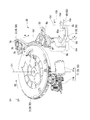
- FIG. 1 is a plan view of a magnetic tape device in a first embodiment of the present invention. It is a perspective view which shows the structure of the conveyance part and lifter part in the embodiment. Similarly, it is a perspective view which shows the structure of the conveyance part and lifter part in the embodiment. It is explanatory drawing regarding operation
- the magnetic tape device 100 is used as an external storage device by loading a cartridge 1 in which a magnetic tape T is accommodated.
- the magnetic tape device 100 pulls out the magnetic tape T accommodated in the cartridge 1 and moves the magnetic tape T along a conveyance path C to be described later, and the magnetic tape T conveyed by the conveyance unit 30.
- a magnetic head 40 that reads and writes data, and a lifter unit 50 that separates the magnetic tape T from the magnetic head 40 when the magnetic tape T is attracted to the magnetic head 40.
- the rotation axes O1, O2, O3, and O4 are assumed to extend along the direction of the arrow UD in FIG.
- the conveying unit 30 is linearly moved along with the rotation of the loader gear 2, a loader gear 2 that is a gear supported to be rotatable around the rotation axis O ⁇ b> 1, a drive device 11 that rotates the loader gear 2.
- a rod bar 3 that performs rotation
- a rotator 8 that rotates about a rotation axis O2 (first rotation axis) by a linear motion of the rod bar 3
- a leader block 9 that removably engages the rotator 8 (see FIG. 3).
- the transport unit 30 includes a plurality of rollers 60 provided at a predetermined interval from the magnetic head 40 described above, and a winding provided so as to be rotatable around the rotation shaft 70 a. And a reel 70.
- the loader gear 2 is a member formed in a disk shape in external view, and teeth are formed on a part of the outer periphery thereof.
- a loader cam 2b is formed on the outer periphery of the loader gear 2 other than the portion where the teeth are formed.
- the drive device 11 has a motor 11a and a gear train 11b driven by the rotation of the motor 11a.
- the motor 11a is electrically connected to a power source (not shown).
- the output shaft of the motor 11a is provided with a gear that forms a part of the gear train 11b. Further, the gear located at the last stage of the gear train 11b meshes with the teeth provided on the loader gear 2 described above. In other words, the output of the motor 11a is transmitted to the loader gear 2 via the gear train 11b.
- the rod bar 3 is a member formed in a substantially square plate shape in external view. At one end of the rod bar 3, a cam groove 3 b is formed so as to mesh with a loader cam 2 b provided on the loader gear 2. That is, with the rotation of the loader gear 2, the rod bar 3 can move linearly in the direction of arrow A in FIG.
- the A direction is a direction orthogonal to the UD direction described above. Therefore, the rod bar 3 can move linearly along the tangential direction on the outer periphery of the loader gear 2.
- the rod bar 3 is urged toward the rear side in the A direction by the spring 3c.
- a shaft portion 3d is formed at an end portion of the rod bar 3 located on the front side in the A direction.
- the rotator 8 is supported so as to be rotatable about a rotation axis O2 provided on the magnetic tape device 100. More specifically, the rotator 8 includes a rotator lever 8a that contacts the rod bar 3 described above, a rotator arm 8b facing the rotator lever 8a in the direction of the rotation axis O2, and the rotator lever 8a and the rotator arm 8b in the direction of the rotation axis O2. And a connecting portion 8c connected to the.
- the tip of the rotator lever 8a is connected to a shaft 3d provided on the rod bar 3. Further, an elongated hole extending in the extending direction of the rotator lever 8a is formed at the tip of the rotator lever 8a. The shaft portion 3d is fitted into the opening of the elongated hole.
- the rotator arm 8b is a part of a member formed in a Y shape when viewed from the outside.
- the member has a shaft portion 8d supported by the rotation shaft O2.
- Three rod-like arms extend radially from the region where the shaft portion 8d is provided. Of these three arms, one arm is a rotator arm 8b.
- An end portion of the rotator arm 8b in a direction away from the shaft portion 8d is disposed so as to abut on a lifter unit body 10 in a lifter unit 50 described later.
- the thus formed rotator lever 8a and rotator arm 8b are connected to each other in the direction in which the rotation axis O2 extends by a connecting portion 8c.
- the connection portion 8c is provided at a position that is eccentric by a predetermined distance from the rotation axis O2 toward the radially outer side. Therefore, a space is formed between the rotator lever 8a and the rotator arm 8b. In this space, a leader block 9 is detachably disposed by a locking portion (not shown).
- the leader block 9 (see FIG. 3) is a member formed in a rectangular parallelepiped shape in an external view. Although not shown in detail, the leader block 9 is provided with an engaging groove (not shown) for engaging with a rod-like leader pin provided at the starting end of the magnetic tape T in the cartridge 1.
- the leader block 9 rotates around the rotation axis O4 in conjunction with the rotator arm 8b at the same time that the rod bar 3 moves in the A direction. With this rotation, the engaging groove of the leader block 9 and the leader pin provided on the magnetic tape T are engaged.
- the magnetic tape T connected to the leader pin is pulled out from the cartridge 1 by moving along a predetermined conveyance path C (details will be described later), and data reading / writing, etc. Provided for use.
- the roller 60 is a columnar member provided so as to be rotatable around a predetermined rotation axis.
- the roller 60 is provided for the purpose of applying an appropriate tension to the magnetic tape T so that the magnetic tape T is not bent in the vicinity of the magnetic head 40 when the magnetic tape T travels. That is, the magnetic tape T travels in a state where it abuts on the outer peripheral surface of the roller 60.
- the conveyance path C is a broken line-shaped path that connects the outer periphery of the plurality of rollers 60 in the conveyance unit 30 and the reading surface 41 of the magnetic head 40.
- the magnetic tape T travels along the transport path C by the transport unit 30. Further, after passing through the conveyance path C, the magnetic tape T is wound around the take-up reel 70 (see FIG. 1).
- moving the magnetic tape T-like storage medium provided with the leader pin at the start end along the transport path C in the magnetic tape device 100 is generally called a threading operation.
- the leader block 9 is disposed in the space formed between the rotator lever 8a and the rotator arm 8b, and then moves on the transport path C by a power source (not shown). That is, after the leader block 9 moves, the state shown in FIG. 3 is obtained.
- a configuration for performing the threading operation for example, a configuration using a drive source, a follower driven by the drive source, and a cam for guiding the follower can be given.
- the follower is attached to the leader block 9 and a follower is made to follow the cam by forming a cam having a shape along the conveyance path C.
- the leader block 9 can be moved along the desired transport path C.
- the lifter unit 50 shares many components with the transport unit 30 described above. That is, the lifter unit 50 includes the drive device 11 (drive unit), the loader gear 2, the rod bar 3, and the rotator 8. Furthermore, the lifter unit 50 has a lifter unit body 10.
- the lifter body 10 is a member that is disposed so as to come into contact with the tip of a rotator arm 8 b provided in the rotator 8.
- the lifter body 10 includes a lifter lever 10a that contacts the rotator arm 8b, a lifter arm 10b (contact portion) that extends along the direction of the rotation axis O3 (second rotation axis), and a lifter base portion 10c that connects them together. And have.
- the lifter base portion 10c is a plate-like and substantially rectangular member that extends on a surface that intersects the rotation axis O3 in an external view.
- An opening 10d that is a circular opening is provided in the central region of the lifter base 10c.
- the opening 10d penetrates the lifter base 10c in the thickness direction.
- the opening 10d is supported by a shaft (not shown) provided in the magnetic tape device 100, and is rotatable about the rotation axis O3. Further, the shaft portion is biased by a spring (not shown). More specifically, it is urged in a direction to rotate counterclockwise around the rotation axis O3 when viewed from one side in the UD direction.
- the lifter lever 10a is a protrusion provided at one end of the lifter base 10c. Further, the lifter arm 10b is a rod-like member provided at an end of the lifter base 10c that faces the lifter lever 10a.
- the lifter arm 10b extends from the lifter base 10c in the direction along the rotation axis O3, and is provided on a surface opposite to the side on which the lifter lever 10a is provided.
- the dimension in the extending direction of the lifter arm 10b is set larger than the dimension in the width direction of the magnetic tape T.
- the lifter body 10 is stopped in the following state by the force of the spring. That is, the lifter arm 10b is stopped in a state where the lifter arm 10b is at a position separated from the conveyance path C.
- This position is the initial position of the lifter body 10 (lifter arm 10b). More specifically, as shown in FIG. 4, the initial position is a position where the lifter arm 10 b is separated in a direction toward the side where the magnetic head 40 is located when viewed from the conveyance path C.
- the conveyance unit 30 and the lifter unit 50 in the magnetic tape device 100 are configured as described above. Next, the operation of the lifter unit 50 in the magnetic tape device 100 will be described with reference to FIGS. The lifter unit 50 operates after the above threading operation in the transport unit 30 is completed.
- the motor 11a in the driving device 11 is driven by a power source (not shown), and the power of the motor 11a is transmitted to the gear train 11b.
- the loader gear 2 that meshes with the gear train 11b rotates about the rotation axis O1 in the R1 direction.
- the rotator 8 rotates about the rotation axis O2. More specifically, when viewed from one side in the UD direction, the rotator 8 rotates counterclockwise around the rotation axis O2. As the rotator 8 rotates, the lifter body 10 rotates about the rotation axis O3. More specifically, when viewed from one side in the UD direction, the lifter body 10 rotates clockwise around the rotation axis O3.
- the magnetic tape T positioned on the transport path C contacts the lifter arm 10b of the lifter body 10.
- the magnetic tape T moves to a position deviating from the transport path C by the lifter arm 10b (see FIG. 5).
- This position is called a lift position of the lifter body 10 (lifter arm 10b).
- the magnetic tape T moves substantially along its own thickness direction by the operation of the lifter arm 10b and deviates from the conveyance path C. This operation is called a lift operation.
- the rod bar 3 moves toward the rear side in the A direction by the elastic restoring force of the spring 3c.
- the rotator 8 rotates about the rotation axis O2 in the clockwise direction when viewed from one side in the UD direction.
- the rotator arm 8b also rotates clockwise around the rotation axis O2 when viewed from one side in the UD direction.
- the lifter body 10 that contacts the rotator arm 8b is biased by a spring (not shown) in the counterclockwise direction around the rotation axis O3 as viewed from one side in the UD direction. Has been.
- the lifter body 10 rotates counterclockwise about the rotation axis O3 by the elastic restoring force of the spring.
- the lifter arm 10b of the lifter unit body 10 moves to the initial position on the transport path C.
- the magnetic tape T moves onto the transport path C by the tension of the magnetic tape T itself. Then, it comes into contact with the magnetic head 40 again. Thereby, operations such as reading and writing of data on the magnetic tape T are performed again.
- the magnetic tape T when the magnetic tape T is on the transport path C, the magnetic tape T is in contact with the magnetic head 40. On the other hand, when the lifter unit 50 performs the lift operation as described above, the magnetic tape T is separated from the magnetic head 40.
- the lifter unit 50 can escape from this state by performing a lift operation. Thereby, the magnetic tape T can appropriately travel on the conveyance path C, and data on the magnetic tape T by the magnetic tape device 100 can be appropriately read and written.
- the lifter unit body 10 in the lifter unit 50 is capable of reciprocating between the initial position and the lift position.
- the lifter unit 50 has both the transport unit 30 and the drive source. That is, the lifter unit 50 is driven by the driving device 11 that drives the transport unit 30. Therefore, the lifter unit 50 can be configured without preparing a drive source different from the drive device 11. Thereby, the number of parts can be reduced, and the manufacturing process can be simplified.
- the size of the lifter arm (contact portion) 10 b in the lifter unit body 10 is set to be larger than the size in the width direction of the magnetic tape T. According to such a configuration, the lifter arm 10b can abut over the entire width direction of the magnetic tape T.
- the lifter arm 10b is formed to be shorter than the width dimension of the magnetic tape T, the magnetic tape T is damaged such as twisting and tearing with the operation of the lifter unit 50 (lifter arm 10b).
- the lifter unit 50 according to the present embodiment can operate without causing damage to the magnetic tape T.
- the lifter unit 50 can reciprocate between the initial position and the lift position, so that the magnetic tape T can be moved. It can be separated from the magnetic head 40.
- the magnetic tape T accommodated in the cartridge 1 has been described as the magnetic tape T.
- the aspect of the magnetic tape T is not limited to the cartridge type.
- the present invention can be applied to a product in which the magnetic tape T is exposed to the outside, such as an open reel deck.
- the present invention can be applied to any product as long as it is a storage medium formed by applying a magnetic material to a strip-shaped thin film.
- the configuration of the gear train 11b in the drive device 11 a worm gear provided on the output shaft of the motor 11a and two circular gears meshing with the worm gear are used.
- the configuration of the gear train 11b is not limited to this configuration, and may be any configuration as long as the rotational power of a motor or the like can be decelerated and transmitted. For example, you may be comprised with the belt and the pulley or the gear and the chain.
- the magnetic tape device 200 according to the present embodiment differs from the first embodiment described above in the following points. That is, the magnetic tape device 200 according to this embodiment includes a magnetic tape T that moves on the conveyance path C, a conveyance unit 30 that moves the magnetic tape T on the conveyance path C, and a magnetic tape T that abuts the magnetic tape T. It has a magnetic head 40 for reading and writing, and a lifter unit 50 provided on the transport path C.
- the same operation as that of the above-described embodiment can be obtained. That is, even when the magnetic tape T is attracted to the magnetic head 40 due to static electricity or the like, it can be removed from this state by operating the lifter unit 50. Thereby, the magnetic tape T can appropriately travel on the conveyance path C, and data on the magnetic tape T by the magnetic tape device 100 can be appropriately read and written.
Landscapes
- Adjustment Of The Magnetic Head Position Track Following On Tapes (AREA)
Abstract
記憶媒体としての磁気テープと、前記磁気テープを搬送経路に沿って移動させる搬送部と、前記搬送経路に配置されて、前記搬送経路上を移動する前記磁気テープに対してデータの読み書きを行う磁気ヘッドと、前記搬送経路に配置されて、前記搬送経路上で停止している前記磁気テープに対して当接するとともに、前記搬送経路と交差する方向に往復移動可能に設けられることで、前記磁気テープを前記磁気ヘッドから離間させるリフター部と、を備える磁気テープ装置。
Description
本発明は、磁気テープ装置及び磁気テープの保全方法に関する。
大量のデータを記録するためのデータストレージ装置として、例えばLTO規格(Linear Tape-Open規格)に代表されるような、磁気テープを用いた磁気テープ装置が知られている。
このような磁気テープ装置は、リールに巻回された状態の磁気テープを収容するカートリッジを磁気テープ装置に装填した後、磁気テープをカートリッジから引き出してデータの読み書きを行う構成となっている。データの読み書きは、磁気テープ装置に備えられた磁気ヘッドに対して磁気テープが当接した状態で、該磁気テープを走行させることで行われる。
一方で、磁気テープへのデータの読み書きが行われていない時には、磁気テープは停止する。磁気テープが停止した状態が比較的長期間にわたる場合、静電気等によって磁気テープが磁気ヘッドに吸着されてしまう。このような状態では、磁気テープが正常に走行しない可能性がある。したがって、磁気テープが停止した状態から再び走行するに先立って、この吸着を解除するために種々の試みがなされている。
このような磁気テープ装置は、リールに巻回された状態の磁気テープを収容するカートリッジを磁気テープ装置に装填した後、磁気テープをカートリッジから引き出してデータの読み書きを行う構成となっている。データの読み書きは、磁気テープ装置に備えられた磁気ヘッドに対して磁気テープが当接した状態で、該磁気テープを走行させることで行われる。
一方で、磁気テープへのデータの読み書きが行われていない時には、磁気テープは停止する。磁気テープが停止した状態が比較的長期間にわたる場合、静電気等によって磁気テープが磁気ヘッドに吸着されてしまう。このような状態では、磁気テープが正常に走行しない可能性がある。したがって、磁気テープが停止した状態から再び走行するに先立って、この吸着を解除するために種々の試みがなされている。
例えば特許文献1には、磁気テープに対してデータの読み書きを行う磁気ヘッドと、磁気テープを走行させる駆動手段と、磁気テープと磁気ヘッドの接触を解除する解除手段と、磁気テープの動作における異常を検出する異常検出手段と、を有する磁気テープ装置が記載されている。
この磁気テープ装置では、異常検出手段によって例えば磁気ヘッドと磁気テープとが吸着された状態のような異常状態が検出されると、解除手段によって磁気テープと磁気ヘッドとが互いに離間し、磁気テープが正常な状態に復旧する。
この磁気テープ装置では、異常検出手段によって例えば磁気ヘッドと磁気テープとが吸着された状態のような異常状態が検出されると、解除手段によって磁気テープと磁気ヘッドとが互いに離間し、磁気テープが正常な状態に復旧する。
しかしながら、上述の特許文献1に記載された磁気テープ装置には、磁気テープと磁気ヘッドとの接触を解除する解除手段を駆動するための駆動源が別途設けられている。したがって、構造が複雑化することで製造コストがかさむとともに、駆動源を設置するためのスペースを新たに用意する必要性も生じる。
本発明は、上記課題を解決するためになされたものであって、製造コストの増大を抑えてコンパクト化を図りながら磁気テープと磁気ヘッドとの接触を解除できる磁気テープ装置、及び、該磁気テープ装置の保全方法を提供することを目的とする。
上記課題を解決するために、本発明は、記憶媒体としての磁気テープと、前記磁気テープを搬送経路に沿って移動させる搬送部と、前記搬送経路に配置されて、前記搬送経路上を移動する前記磁気テープに対してデータの読み書きを行う磁気ヘッドと、前記搬送経路に配置されて、前記搬送経路上で停止している前記磁気テープに対して当接するとともに、前記搬送経路と交差する方向に往復移動可能に設けられることで、前記磁気テープを前記磁気ヘッドから離間させるリフター部と、を備える磁気テープ装置を提供する。
また、本発明は、記憶媒体としての磁気テープと、前記磁気テープを搬送経路に沿って移動させる搬送部と、前記搬送経路に配置されて、前記搬送経路を移動する前記磁気テープに対してデータの読み書きを行う磁気ヘッドと、前記搬送経路に配置されるリフター部と、を備える磁気テープ装置を用いた磁気テープの保全方法であって、前記リフター部を前記搬送経路上で停止している前記磁気テープに対して当接させ、前記搬送経路と交差する方向に往復移動させることで、前記磁気テープを前記磁気ヘッドから離間させる方法も提供する。
本発明の磁気テープ装置及び磁気テープの保全方法によれば、製造コストの増大を抑えることができるとともに、装置のコンパクト化を図ることができる。
以下、本発明の第一実施形態に係る磁気テープ装置100について、図1から図5を参照して説明する。
図1に示すように、磁気テープ装置100は、内部に磁気テープTが収容されたカートリッジ1が装填されることで、外部記憶装置としての使用に供されるものである。
磁気テープ装置100は、カートリッジ1に収容された磁気テープTを引き出すとともに、磁気テープTを後述する搬送経路Cに沿って移動させる搬送部30と、搬送部30によって搬送された磁気テープTに対してデータの読み書きを行う磁気ヘッド40と、磁気ヘッド40に磁気テープTが吸着された場合に磁気テープTを磁気ヘッド40から離間させるリフター部50と、を備えている。
図1に示すように、磁気テープ装置100は、内部に磁気テープTが収容されたカートリッジ1が装填されることで、外部記憶装置としての使用に供されるものである。
磁気テープ装置100は、カートリッジ1に収容された磁気テープTを引き出すとともに、磁気テープTを後述する搬送経路Cに沿って移動させる搬送部30と、搬送部30によって搬送された磁気テープTに対してデータの読み書きを行う磁気ヘッド40と、磁気ヘッド40に磁気テープTが吸着された場合に磁気テープTを磁気ヘッド40から離間させるリフター部50と、を備えている。
搬送部30の構成について、図2を参照して説明する。なお、以下の説明では、回転軸O1,O2,O3、O4は、図2中における矢印U-D方向に沿って延びるものとする。
図2に示すように搬送部30は、回転軸O1回りに回動可能に支持される歯車であるローダギア2と、ローダギア2を回転駆動する駆動装置11と、ローダギア2の回転に伴って直線運動を行うロッドバー3と、ロッドバー3の直線運動によって回転軸O2(第一回転軸)回りに回動するローテータ8と、ローテータ8に対して着脱可能に係合するリーダブロック9(図3参照)と、を有している。
さらに、図1に示すように、搬送部30は、上述の磁気ヘッド40と互いに所定の間隔を開けて設けられた複数のローラー60と、回転軸70a回りに回動可能に設けられた巻き取りリール70と、を備えている。
図2に示すように搬送部30は、回転軸O1回りに回動可能に支持される歯車であるローダギア2と、ローダギア2を回転駆動する駆動装置11と、ローダギア2の回転に伴って直線運動を行うロッドバー3と、ロッドバー3の直線運動によって回転軸O2(第一回転軸)回りに回動するローテータ8と、ローテータ8に対して着脱可能に係合するリーダブロック9(図3参照)と、を有している。
さらに、図1に示すように、搬送部30は、上述の磁気ヘッド40と互いに所定の間隔を開けて設けられた複数のローラー60と、回転軸70a回りに回動可能に設けられた巻き取りリール70と、を備えている。
ローダギア2は、外形視で円盤状に形成された部材であって、その外周の一部分には歯が形成されている。また、ローダギア2の外周における、歯が形成された部分以外の部分には、径方向外側に向かって突出するローダカム2bが形成されている。
駆動装置11は、モータ11aと、モータ11aの回転によって駆動されるギア列11bと、を有している。
モータ11aは、不図示の電源に対して電気的に接続されている。また、モータ11aの出力軸にはギア列11bの一部を形成するギアが設けられている。
さらに、ギア列11bの最後段に位置するギアは、上述のローダギア2に設けられた歯と噛み合う。換言すれば、モータ11aの出力は、ギア列11bを介してローダギア2に伝達される。
モータ11aは、不図示の電源に対して電気的に接続されている。また、モータ11aの出力軸にはギア列11bの一部を形成するギアが設けられている。
さらに、ギア列11bの最後段に位置するギアは、上述のローダギア2に設けられた歯と噛み合う。換言すれば、モータ11aの出力は、ギア列11bを介してローダギア2に伝達される。
ロッドバー3は、外形視で概ね方形板状に形成された部材である。ロッドバー3の一方の端部には、ローダギア2に設けられたローダカム2bと噛み合うような形状のカム溝3bが形成されている。すなわち、ローダギア2の回転に伴って、ロッドバー3は、図2における矢印Aの方向に直線的に運動することができる。
ここで、A方向とは、上述のU-D方向に直交する方向である。したがって、ロッドバー3は、ローダギア2の外周における接線の方向に沿って直線的に運動することができる。
加えて、ロッドバー3は、バネ3cによって、A方向後方側に向かって付勢されている。
さらに、ロッドバー3のA方向前方側に位置する端部には、軸部3dが形成されている。
ここで、A方向とは、上述のU-D方向に直交する方向である。したがって、ロッドバー3は、ローダギア2の外周における接線の方向に沿って直線的に運動することができる。
加えて、ロッドバー3は、バネ3cによって、A方向後方側に向かって付勢されている。
さらに、ロッドバー3のA方向前方側に位置する端部には、軸部3dが形成されている。
ローテータ8は、磁気テープ装置100上に設けられた回転軸O2回りに回動可能に支持される。より詳しくは、ローテータ8は、上述のロッドバー3と当接するローテータレバー8aと、ローテータレバー8aと回転軸O2方向に対向するローテータアーム8bと、これらローテータレバー8aとローテータアーム8bとを回転軸O2方向に接続する接続部8cと、から構成されている。
ローテータレバー8aの先端部は、ロッドバー3に設けられた軸部3dと接続されている。また、ローテータレバー8aの先端部には、ローテータレバー8aの延在する方向に延びる長穴が形成されている。軸部3dはこの長穴の開口に対してはめ込まれている。
ローテータアーム8bは、外形視でY字状に形成された部材の一部である。当該部材は、回転軸O2によって支持される軸部8dを有している。この軸部8dが設けられた領域から、3つの棒状のアームがおおむね放射状に延びている。これら3つのアームのうち、1つのアームがローテータアーム8bとされている。
ローテータアーム8bにおける、軸部8dから離間する方向における端部は、後述するリフター部50におけるリフター部本体10に当接するように配置される。
ローテータアーム8bにおける、軸部8dから離間する方向における端部は、後述するリフター部50におけるリフター部本体10に当接するように配置される。
このように形成されたローテータレバー8aと、ローテータアーム8bとは、接続部8cによって、回転軸O2の延びる方向に互いに接続されている。接続部8cは、回転軸O2から径方向外側に向かって所定の距離だけ偏心した位置に設けられている。したがって、ローテータレバー8aと、ローテータアーム8bとの間には空間が形成されている。この空間には、不図示の係止部によってリーダブロック9が脱着可能に配置される。
リーダブロック9(図3参照)は、外形視で直方体状に形成された部材である。詳細は図示しないが、リーダブロック9には、カートリッジ1における磁気テープTの始端に設けられた棒状のリーダピンと係合するための係合溝(不図示)が設けられている。
リーダブロック9は、ロッドバー3がA方向に移動すると同時に、ローテータアーム8bと連動して回転軸O4回りに回転する。この回転に伴ってリーダブロック9の係合溝と、磁気テープTに設けられたリーダピンとが係合する。
リーダブロック9がリーダピンと係合した後、所定の搬送経路C(詳細は後述)に沿って移動することにより、リーダピンに接続された磁気テープTはカートリッジ1から引き出されて、データの読み書き等の利用に供される。
ローラー60は、所定の回転軸回りに回動可能に設けられた円柱状の部材である。ローラー60は、磁気テープTが走行するに際して、磁気ヘッド40の近傍で磁気テープTに撓み等が生じることのないように、磁気テープTに適正なテンションを付加する目的で設けられるものである。すなわち、磁気テープTは、ローラー60の外周面に当接した状態で走行する。
搬送経路Cは、図4に示すように、搬送部30における複数のローラー60の外周と、磁気ヘッド40の読み取り面41と、を結んだ折線状の経路である。
磁気テープTは、搬送部30によって搬送経路Cに沿って走行する。さらに、磁気テープTは搬送経路Cを通過した後、巻き取りリール70(図1参照)に対して巻回される。
磁気テープTは、搬送部30によって搬送経路Cに沿って走行する。さらに、磁気テープTは搬送経路Cを通過した後、巻き取りリール70(図1参照)に対して巻回される。
上述のように、始端にリーダピンが設けられた磁気テープT様の記憶媒体を磁気テープ装置100における搬送経路Cに沿って移動させることは、一般にスレッディング動作と呼ばれるものである。
リーダブロック9は、上述したようにローテータレバー8aと、ローテータアーム8bとの間に形成された空間に配置された後、不図示の動力源によって搬送経路C上を移動する。すなわち、リーダブロック9が移動した後は、図3に示すような状態となる。
上記スレッディング動作を行うための構成として、例えば駆動源と、該駆動源によって駆動されるフォロワと、フォロワを案内するカムとを用いる構成が挙げられる。この構成では、リーダブロック9にフォロワを取り付けるとともに、搬送経路Cに沿った形状のカムを形成することで、フォロワをカムに追従させる。このような構成によれば、所望の搬送経路Cに沿ってリーダブロック9を移動させることができる。
続いて、リフター部50の構成について図2を参照して説明する。
リフター部50は、上述の搬送部30と、多くの構成要素を共にしている。すなわち、リフター部50は、駆動装置11(駆動部)と、ローダギア2と、ロッドバー3と、ローテータ8と、を有している。さらに、リフター部50は、リフター部本体10を有している。
リフター部50は、上述の搬送部30と、多くの構成要素を共にしている。すなわち、リフター部50は、駆動装置11(駆動部)と、ローダギア2と、ロッドバー3と、ローテータ8と、を有している。さらに、リフター部50は、リフター部本体10を有している。
以下の説明において、搬送部30と共通の構成要素についてはその詳細な説明を省略し、リフター部本体10の構成について特に説明する。
図2に示すように、リフター部本体10は、ローテータ8に設けられたローテータアーム8bの先端部と当接するように配置される部材である。リフター部本体10は、ローテータアーム8bと当接するリフターレバー10aと、回転軸O3(第二回転軸)の方向に沿って延びるリフターアーム10b(当接部)と、これらを互いに接続するリフター基部10cと、を有している。
リフター基部10cは、回転軸O3と交差する面上に延在する、外形視で板状かつ概略矩形の部材である。リフター基部10cの中央領域には、円形の開口である開口部10dが設けられている。開口部10dは、リフター基部10cを、厚さ方向に貫通している。
この開口部10dは、磁気テープ装置100に設けられた不図示の軸部によって支持されて、回転軸O3の回りに回動可能とされている。さらに、この軸部は不図示のバネによって付勢されている。より詳細には、U-D方向一方側から見て、回転軸O3回りに反時計回りに回転する方向に付勢されている。
この開口部10dは、磁気テープ装置100に設けられた不図示の軸部によって支持されて、回転軸O3の回りに回動可能とされている。さらに、この軸部は不図示のバネによって付勢されている。より詳細には、U-D方向一方側から見て、回転軸O3回りに反時計回りに回転する方向に付勢されている。
リフターレバー10aは、リフター基部10cの一端部に設けられた突出部である。さらに、リフターアーム10bは、リフター基部10cにおける、リフターレバー10aと対向する端部に設けられた棒状部材である。
リフターアーム10bは、リフター基部10c上から、回転軸O3に沿う方向に延びるとともに、リフターレバー10aが設けられる側と反対側の面に設けられている。リフターアーム10bの延在する方向における寸法は、磁気テープTの幅方向の寸法よりも大きく設定されている。
なお、ローテータ8からの力が付加されていない状態にあっては、リフター部本体10はバネの力によって、以下のような状態で停止している。すなわち、リフターアーム10bが搬送経路Cから離間した位置にあるような状態で停止している。この位置をリフター部本体10(リフターアーム10b)の初期位置とする。より詳細には、当該初期位置は、図4に示すように、リフターアーム10bが搬送経路Cから見て磁気ヘッド40が位置する側に向かう方向に離間した位置である。
なお、ローテータ8からの力が付加されていない状態にあっては、リフター部本体10はバネの力によって、以下のような状態で停止している。すなわち、リフターアーム10bが搬送経路Cから離間した位置にあるような状態で停止している。この位置をリフター部本体10(リフターアーム10b)の初期位置とする。より詳細には、当該初期位置は、図4に示すように、リフターアーム10bが搬送経路Cから見て磁気ヘッド40が位置する側に向かう方向に離間した位置である。
磁気テープ装置100における搬送部30とリフター部50とは、以上のように構成される。
次に、この磁気テープ装置100におけるリフター部50の動作について、図3から図5を参照して説明する。なお、リフター部50は、搬送部30における上述のスレッディング動作が完了した後に動作するものである。
次に、この磁気テープ装置100におけるリフター部50の動作について、図3から図5を参照して説明する。なお、リフター部50は、搬送部30における上述のスレッディング動作が完了した後に動作するものである。
まず、駆動装置11におけるモータ11aが不図示の電源によって駆動され、モータ11aの動力がギア列11bに伝達される。ギア列11bに伝達された動力によって、ギア列11bと噛み合うローダギア2が回転軸O1回りにR1方向に向かって回動する。
ローダギア2がR1方向に回動すると、ローダギア2に設けられたローダカム2bと、ロッドバー3に設けられたカム溝3bとが互いに噛み合う。これらローダカム2bと、カム溝3bとが互いに噛み合った状態で、さらにローダギア2が回動することによって、ロッドバー3は図3における矢印Aの方向に直線移動する。
ロッドバー3の移動に伴って、ローテータ8が回転軸O2回りに回動する。より詳細には、U-D方向一方側から見てローテータ8は回転軸O2回りに反時計回りに回転する。
ローテータ8の回転に伴って、リフター部本体10は回転軸O3回りに回動する。より詳細には、U-D方向一方側から見てリフター部本体10は回転軸O3回りに時計回りに回動する。
ローテータ8の回転に伴って、リフター部本体10は回転軸O3回りに回動する。より詳細には、U-D方向一方側から見てリフター部本体10は回転軸O3回りに時計回りに回動する。
リフター部本体10が回転軸O3を中心として時計回りに回動すると、搬送経路C上に位置する磁気テープTは、リフター部本体10のリフターアーム10bに当接する。この状態から、リフター部本体10がさらに回動すると、磁気テープTは、リフターアーム10bによって、搬送経路Cから逸脱した位置に移動する(図5参照)。この位置をリフター部本体10(リフターアーム10b)のリフト位置と呼ぶ。
換言すると、リフターアーム10bの動作によって、磁気テープTはおおむね自身の厚さ方向に沿って移動し、搬送経路Cから逸脱する。この動作をリフト動作と呼ぶ。
換言すると、リフターアーム10bの動作によって、磁気テープTはおおむね自身の厚さ方向に沿って移動し、搬送経路Cから逸脱する。この動作をリフト動作と呼ぶ。
次に、リフト動作が完了した後のリフター部50の動作について説明する。
リフト動作が完了すると、ローダギア2はさらに回動を続ける。ローダギア2が回動を続けると、ローダギア2に設けられたローダカム2bと、ロッドバー3に設けられたカム溝3bとの噛み合いが解除される。
リフト動作が完了すると、ローダギア2はさらに回動を続ける。ローダギア2が回動を続けると、ローダギア2に設けられたローダカム2bと、ロッドバー3に設けられたカム溝3bとの噛み合いが解除される。
ローダカム2bとカム溝3bとの噛み合いが解除されると、ロッドバー3は上述のバネ3cの弾性復元力によってA方向後方側に向かって移動する。
ロッドバー3のA方向後方側への移動に伴って、ローテータ8は回転軸O2を中心として、U-D方向一方側から見て時計回りに回動する。これにより、ローテータアーム8bも、回転軸O2を中心として、U-D方向一方側から見て時計回りに回動する。
ロッドバー3のA方向後方側への移動に伴って、ローテータ8は回転軸O2を中心として、U-D方向一方側から見て時計回りに回動する。これにより、ローテータアーム8bも、回転軸O2を中心として、U-D方向一方側から見て時計回りに回動する。
ここで、上述したように、ローテータアーム8bと当接するリフター部本体10は、不図示のバネによって、回転軸O3を中心として、U-D方向一方側から見て反時計回りの方向に付勢されている。
したがって、ローテータ8が回転軸O2を中心として時計回りに回動するに伴って、リフター部本体10は、このバネの弾性復元力によって、回転軸O3を中心として反時計回りに回動する。
これにより、リフター部本体10のリフターアーム10bは搬送経路C上の初期位置に移動する。ここで、上述のように磁気テープTはローラー60等によってテンションが付加されている状態であるため、リフターアーム10bが初期位置に移動すると、磁気テープT自身のテンションによって搬送経路C上に移動して、磁気ヘッド40と再び当接する。これにより、再び磁気テープT上のデータの読み書き等の操作が行われる。
上述のような構成によれば、磁気テープTが搬送経路C上にあるときは、磁気テープTは磁気ヘッド40に対して当接している。一方で、リフター部50が上述のようにリフト動作を行うことによって、磁気テープTは磁気ヘッド40から離間する。
すなわち、磁気テープTが静電気等の要因によって磁気ヘッド40に吸着されている場合であっても、リフター部50がリフト動作を行うことによって、この状態から脱することができる。これにより、磁気テープTは適切に搬送経路C上を走行することができ、磁気テープ装置100による磁気テープT上のデータを適切に読み書きすることができる。
以上説明したように、リフター部50におけるリフター部本体10は、上述の初期位置とリフト位置との間を往復移動可能とされている。
以上説明したように、リフター部50におけるリフター部本体10は、上述の初期位置とリフト位置との間を往復移動可能とされている。
さらに、上述の構成によれば、リフター部50は、搬送部30と駆動源をともにしている。すなわち、リフター部50は、搬送部30を駆動する駆動装置11によって駆動される。したがって、駆動装置11とは別の駆動源を用意しなくても、リフター部50を構成することができる。これにより、部品点数を削減することができるとともに、製造工程を簡略化することができる。
加えて、上述の構成では、リフター部本体10におけるリフターアーム(当接部)10bの寸法は、磁気テープTの幅方向の寸法よりも大きく設定されている。
このような構成によれば、リフターアーム10bは磁気テープTの幅方向全体にわたって当接することができる。
ここで、リフターアーム10bが磁気テープTの幅寸法よりも短く形成されている場合には、リフター部50(リフターアーム10b)の動作に伴って、磁気テープTにねじれや破れ等の損壊を生じる可能性がある。
しかしながら、上述のように構成されていることにより、本実施形態にかかるリフター部50は、磁気テープTに損壊を生じることなく動作することができる。
このような構成によれば、リフターアーム10bは磁気テープTの幅方向全体にわたって当接することができる。
ここで、リフターアーム10bが磁気テープTの幅寸法よりも短く形成されている場合には、リフター部50(リフターアーム10b)の動作に伴って、磁気テープTにねじれや破れ等の損壊を生じる可能性がある。
しかしながら、上述のように構成されていることにより、本実施形態にかかるリフター部50は、磁気テープTに損壊を生じることなく動作することができる。
さらに、上述のように構成されたリフター部50を用いた磁気テープTの保全方法によれば、リフター部50が初期位置とリフト位置との間で往復移動可能であることによって、磁気テープTを磁気ヘッド40から離間させることができる。
すなわち、磁気テープTが静電気等の要因によって磁気ヘッド40に吸着されている場合であっても、リフター部50を動作させることによって、この状態を脱することができる。これにより、磁気テープTは適切に搬送経路C上を走行することができ、磁気テープ装置100による磁気テープT上のデータを適切に読み書きすることができる。
以上、本発明の第一実施形態について図面を参照して詳述したが、各実施形態における各構成及びそれらの組み合わせ等は一例であり、本発明の趣旨から逸脱しない範囲内で、構成の付加、省略、置換、及びその他の変更が可能である。また、本発明は実施形態によって限定されることはなく、クレームの範囲によってのみ限定される。
なお、上述の実施形態では、磁気テープTとして、カートリッジ1に収容された磁気テープTを説明した。しかし、磁気テープTの態様はカートリッジ式に限定されない。例えば、オープンリールデッキ等、磁気テープTが外部に露出した状態の製品に対しても適用可能である。より広義には、帯状の薄膜に磁性体を塗布して形成される記憶媒体である限りにおいては、本発明はいかなる製品に対しても適用可能である。
さらに、本実施形態では駆動装置11におけるギア列11bの構成として、モータ11aの出力軸に設けられるウォームギアと、これに噛み合う2つの円形のギアを用いている。しかしながら、ギア列11bの構成はこの構成に限定されず、モータ等の回転動力を減速・伝達できる限りにおいてはいかなる構成であってもよい。例えば、ベルトとプーリー、又はギアとチェーンによって構成されていてもよい。
次に、本発明の第二実施形態について、図6を参照して説明する。
本実施形態に係る磁気テープ装置200は、以下の点で上述の第一実施形態と異なる。
すなわち、本実施形態に係る磁気テープ装置200は、搬送経路C上を移動する磁気テープTと、磁気テープTを搬送経路C上で走行させる搬送部30と、磁気テープTに当接してデータの読み書きを行う磁気ヘッド40と、搬送経路C上に設けられるリフター部50と、を有している。
本実施形態に係る磁気テープ装置200は、以下の点で上述の第一実施形態と異なる。
すなわち、本実施形態に係る磁気テープ装置200は、搬送経路C上を移動する磁気テープTと、磁気テープTを搬送経路C上で走行させる搬送部30と、磁気テープTに当接してデータの読み書きを行う磁気ヘッド40と、搬送経路C上に設けられるリフター部50と、を有している。
このような構成であっても、上述の実施形態と同様の作用を得ることができる。すなわち、磁気テープTが静電気等の要因によって磁気ヘッド40に吸着されている場合であっても、リフター部50が動作することによって、この状態から脱することができる。これにより、磁気テープTは適切に搬送経路C上を走行することができ、磁気テープ装置100による磁気テープT上のデータを適切に読み書きすることができる。
この出願は、2014年3月31日に出願された日本出願特願2014-070898号を基礎とする優先権を主張し、その開示の全てをここに取り込む。
本発明によれば、製造コストの増大を抑えることができるとともに、装置のコンパクト化を図ることができる。
T 磁気テープ
C 搬送経路
100、200 磁気テープ装置
1 カートリッジ
2 ローダギア
2b ローダカム
3 ロッドバー
3b カム溝
3c バネ
3d 軸部
8 ローテータ
8a ローテータレバー
8b ローテータアーム
8c 接続部
8d 軸部
9 リーダブロック
10 リフター部本体
10a リフターレバー
10b リフターアーム(当接部)
10c リフター基部
10d 開口部
11 駆動装置
11a モータ
11b ギア列
30 搬送部
40 磁気ヘッド
50 リフター部
60 ローラー
70 巻き取りリール
70a 回転軸
O1、O2、O3、O4 回転軸
C 搬送経路
100、200 磁気テープ装置
1 カートリッジ
2 ローダギア
2b ローダカム
3 ロッドバー
3b カム溝
3c バネ
3d 軸部
8 ローテータ
8a ローテータレバー
8b ローテータアーム
8c 接続部
8d 軸部
9 リーダブロック
10 リフター部本体
10a リフターレバー
10b リフターアーム(当接部)
10c リフター基部
10d 開口部
11 駆動装置
11a モータ
11b ギア列
30 搬送部
40 磁気ヘッド
50 リフター部
60 ローラー
70 巻き取りリール
70a 回転軸
O1、O2、O3、O4 回転軸
Claims (4)
- 記憶媒体としての磁気テープと、
前記磁気テープを搬送経路に沿って移動させる搬送部と、
前記搬送経路に配置されて、前記搬送経路上を移動する前記磁気テープに対してデータの読み書きを行う磁気ヘッドと、
前記搬送経路に配置されて、前記搬送経路上で停止している前記磁気テープに対して当接するとともに、前記搬送経路と交差する方向に往復移動可能に設けられることで、前記磁気テープを前記磁気ヘッドから離間させるリフター部と、
を備えることを特徴とする磁気テープ装置。 - 前記搬送部は、前記磁気テープを前記搬送経路に沿って移動させる駆動部を有し、
前記リフター部は、
第一回転軸回りに回動可能に支持されるローテータと、
一端が前記ローテータに当接して、第二回転軸回りに回動可能に支持されるとともに、他端が前記磁気テープに当接するリフター部本体と、
を有し、
前記ローテータは、前記駆動部からの駆動力によって回動して前記リフター部本体を回動させることを特徴とする請求項1に記載の磁気テープ装置。 - 前記リフター部本体は、前記磁気テープに当接する当接部を有し、
前記磁気テープの幅方向において、前記当接部の寸法は、前記磁気テープの寸法よりも大きいことを特徴とする
請求項2に記載の磁気テープ装置。 - 記憶媒体としての磁気テープと、
前記磁気テープを搬送経路に沿って移動させる搬送部と、
前記搬送経路に配置されて、前記搬送経路を移動する前記磁気テープに対してデータの読み書きを行う磁気ヘッドと、
前記搬送経路に配置されるリフター部と、
を備える磁気テープ装置を用いた磁気テープの保全方法であって、
前記リフター部を前記搬送経路上で停止している前記磁気テープに対して当接させ、
前記搬送経路と交差する方向に往復移動させることで、前記磁気テープを前記磁気ヘッドから離間させる
ことを特徴とする磁気テープの保全方法。
Priority Applications (1)
| Application Number | Priority Date | Filing Date | Title |
|---|---|---|---|
| US15/129,329 US9870794B2 (en) | 2014-03-31 | 2015-03-26 | Magnetic tape device and magnetic tape maintenance method |
Applications Claiming Priority (2)
| Application Number | Priority Date | Filing Date | Title |
|---|---|---|---|
| JP2014-070898 | 2014-03-31 | ||
| JP2014070898A JP6436471B2 (ja) | 2014-03-31 | 2014-03-31 | 磁気テープ装置及び磁気テープの保全方法 |
Publications (1)
| Publication Number | Publication Date |
|---|---|
| WO2015151995A1 true WO2015151995A1 (ja) | 2015-10-08 |
Family
ID=54240321
Family Applications (1)
| Application Number | Title | Priority Date | Filing Date |
|---|---|---|---|
| PCT/JP2015/059374 Ceased WO2015151995A1 (ja) | 2014-03-31 | 2015-03-26 | 磁気テープ装置及び磁気テープの保全方法 |
Country Status (3)
| Country | Link |
|---|---|
| US (1) | US9870794B2 (ja) |
| JP (1) | JP6436471B2 (ja) |
| WO (1) | WO2015151995A1 (ja) |
Cited By (2)
| Publication number | Priority date | Publication date | Assignee | Title |
|---|---|---|---|---|
| JP7578783B1 (ja) | 2023-11-16 | 2024-11-06 | Necプラットフォームズ株式会社 | テープリフター機構、および磁気テープ装置 |
| JP7623439B1 (ja) | 2023-08-01 | 2025-01-28 | Necプラットフォームズ株式会社 | 磁気テープ装置、磁気テープ装置の制御方法および磁気テープ装置の制御プログラム |
Families Citing this family (7)
| Publication number | Priority date | Publication date | Assignee | Title |
|---|---|---|---|---|
| US9837104B1 (en) | 2016-10-31 | 2017-12-05 | International Business Machines Corporation | Tape head having sensors proximate to an edge |
| US9928855B1 (en) | 2016-10-31 | 2018-03-27 | International Business Machines Corporation | Tape head and system having asymmetrical construction |
| US10068591B2 (en) | 2016-12-05 | 2018-09-04 | International Business Machines Corporation | Head having wrap-controlled flexible media interface |
| US10418059B2 (en) | 2016-12-06 | 2019-09-17 | International Business Machines Corporation | Methods for selecting wrap angle for inducing tape tenting above transducer |
| JP6870842B2 (ja) * | 2017-02-03 | 2021-05-12 | Necプラットフォームズ株式会社 | 磁気テープ装置、磁気記録装置、及び磁気テープ装置におけるテープリフト方法 |
| JP6596054B2 (ja) | 2017-10-19 | 2019-10-23 | Necプラットフォームズ株式会社 | 磁気ヘッドクリーニング機構及び磁気テープ装置 |
| JP6616539B1 (ja) * | 2019-02-15 | 2019-12-04 | Necプラットフォームズ株式会社 | 清掃可能化装置、清掃装置及び磁気テープ装置 |
Citations (3)
| Publication number | Priority date | Publication date | Assignee | Title |
|---|---|---|---|---|
| JPH0896438A (ja) * | 1994-09-20 | 1996-04-12 | Fujitsu Ltd | 磁気テープ装置 |
| US20070064340A1 (en) * | 2005-09-22 | 2007-03-22 | Quantum Corporation | Tape deflector having integrated roller |
| JP2009211754A (ja) * | 2008-03-04 | 2009-09-17 | Nec Personal Products Co Ltd | 磁気テープ装置 |
Family Cites Families (17)
| Publication number | Priority date | Publication date | Assignee | Title |
|---|---|---|---|---|
| US2560254A (en) * | 1948-03-26 | 1951-07-10 | Rca Corp | Device for separating the magnetic transducer and record member during rewind |
| US2975242A (en) * | 1957-12-18 | 1961-03-14 | Telefunken Gmbh | Drive mechanism for magnetic recording deck |
| US4426750A (en) * | 1982-08-09 | 1984-01-24 | Storage Technology Corporation | Combined rewind foot/tape cleaner |
| JPS62114149A (ja) * | 1985-11-13 | 1987-05-25 | Fujitsu Ltd | 磁気テ−プ装置 |
| US4656534A (en) * | 1986-03-10 | 1987-04-07 | Hewlett-Packard Company | Anti-adhesion device for magnetic tape drive |
| JPH04360011A (ja) * | 1991-06-06 | 1992-12-14 | Matsushita Electric Ind Co Ltd | 磁気記録再生装置 |
| US5739970A (en) * | 1994-09-20 | 1998-04-14 | Fujitsu Limited | Magnetic tape unit |
| JPH08235823A (ja) * | 1995-02-28 | 1996-09-13 | Sony Corp | 磁気テープ巻き取り装置 |
| JPH08273250A (ja) * | 1995-03-31 | 1996-10-18 | Aiwa Co Ltd | テープレコーダ |
| JPH11328633A (ja) * | 1998-03-13 | 1999-11-30 | Hewlett Packard Co <Hp> | テ―プドライブ、及びトランスデュ―サ・ヘッドに対する損傷を低減する方法 |
| US7558021B2 (en) * | 2006-04-21 | 2009-07-07 | Quantum Corporation | Hub lock/head cleaning dual purpose mechanism |
| JP2008287850A (ja) * | 2007-04-20 | 2008-11-27 | Hitachi Maxell Ltd | 磁気テープ駆動装置 |
| US7782567B2 (en) * | 2007-07-23 | 2010-08-24 | International Business Machines Corporation | Cleaning system for tape head and tape drive system implementing same |
| US8218265B2 (en) * | 2008-08-14 | 2012-07-10 | International Business Machines Corporation | Apparatus, system, and method for overcoming stiction in a magnetic tape device |
| US9058836B2 (en) * | 2009-01-29 | 2015-06-16 | Hewlett-Packard Development Company, L.P. | Data transfer apparatus |
| JP2012216256A (ja) * | 2011-03-31 | 2012-11-08 | Fujifilm Corp | 情報記録システム及びマガジン |
| JP6489606B2 (ja) * | 2014-11-12 | 2019-03-27 | Necプラットフォームズ株式会社 | 磁気テープ案内装置、方法、及び磁気テープ記録装置 |
-
2014
- 2014-03-31 JP JP2014070898A patent/JP6436471B2/ja active Active
-
2015
- 2015-03-26 WO PCT/JP2015/059374 patent/WO2015151995A1/ja not_active Ceased
- 2015-03-26 US US15/129,329 patent/US9870794B2/en not_active Expired - Fee Related
Patent Citations (3)
| Publication number | Priority date | Publication date | Assignee | Title |
|---|---|---|---|---|
| JPH0896438A (ja) * | 1994-09-20 | 1996-04-12 | Fujitsu Ltd | 磁気テープ装置 |
| US20070064340A1 (en) * | 2005-09-22 | 2007-03-22 | Quantum Corporation | Tape deflector having integrated roller |
| JP2009211754A (ja) * | 2008-03-04 | 2009-09-17 | Nec Personal Products Co Ltd | 磁気テープ装置 |
Cited By (3)
| Publication number | Priority date | Publication date | Assignee | Title |
|---|---|---|---|---|
| JP7623439B1 (ja) | 2023-08-01 | 2025-01-28 | Necプラットフォームズ株式会社 | 磁気テープ装置、磁気テープ装置の制御方法および磁気テープ装置の制御プログラム |
| JP7578783B1 (ja) | 2023-11-16 | 2024-11-06 | Necプラットフォームズ株式会社 | テープリフター機構、および磁気テープ装置 |
| WO2025105247A1 (ja) * | 2023-11-16 | 2025-05-22 | Necプラットフォームズ株式会社 | テープリフター機構、および磁気テープ装置 |
Also Published As
| Publication number | Publication date |
|---|---|
| JP2015191681A (ja) | 2015-11-02 |
| US9870794B2 (en) | 2018-01-16 |
| US20170178679A1 (en) | 2017-06-22 |
| JP6436471B2 (ja) | 2018-12-12 |
Similar Documents
| Publication | Publication Date | Title |
|---|---|---|
| JP6436471B2 (ja) | 磁気テープ装置及び磁気テープの保全方法 | |
| CN103165140A (zh) | 用于控制磁头的移动的磁带装置和方法 | |
| WO2019078245A1 (ja) | 磁気ヘッドクリーニング機構及び磁気テープ装置 | |
| US11657838B2 (en) | Cleaning enabling device, cleaning device, and magnetic tape device | |
| JP2707289B2 (ja) | 情報記録再生装置 | |
| US20130021694A1 (en) | Self-contained magnetic tape drive and combined multi-part tape system | |
| JP5808855B2 (ja) | ヘッドクリーニング装置及びドライブ装置 | |
| JP2010102762A (ja) | ライブラリ装置及びカートリッジの搬送方法 | |
| US8284519B2 (en) | Magnetic head cleaning mechanism of threading scheme magnetic tape apparatus | |
| JP6446500B2 (ja) | 光学テープ駆動可動平坦化装置サブシステム、および光ピックアップユニットに対する損傷を最小限にするための方法 | |
| JP6261029B2 (ja) | 磁気テープ装置 | |
| JP6489606B2 (ja) | 磁気テープ案内装置、方法、及び磁気テープ記録装置 | |
| JP2013073638A (ja) | 磁気テープ装置 | |
| JP2014207048A (ja) | 磁気ヘッドクリーニング機構及び磁気テープ装置 | |
| US3949951A (en) | Tape cartridge drive | |
| US7672078B2 (en) | Magnetic recording/reproducing apparatus | |
| US11393504B2 (en) | Magnetic tape device, magnetic recording device, and tape lifting method for magnetic tape device | |
| JPS5919265A (ja) | 磁気テ−プ装置 | |
| JP2013069383A (ja) | 巻き取りリールおよび磁気テープ装置 | |
| JP6194846B2 (ja) | 磁気テープ装置 | |
| US20140115614A1 (en) | Data storage device tape path cleaner | |
| WO2012124429A1 (ja) | ドライブ装置 | |
| JP2015070229A (ja) | 巻線装置及び巻線方法 | |
| JP2005190666A (ja) | テープドライブ装置 | |
| JP2013045476A (ja) | 光ディスク収納マガジン、およびディスクチェンジャー |
Legal Events
| Date | Code | Title | Description |
|---|---|---|---|
| 121 | Ep: the epo has been informed by wipo that ep was designated in this application |
Ref document number: 15774481 Country of ref document: EP Kind code of ref document: A1 |
|
| WWE | Wipo information: entry into national phase |
Ref document number: 15129329 Country of ref document: US |
|
| NENP | Non-entry into the national phase |
Ref country code: DE |
|
| 122 | Ep: pct application non-entry in european phase |
Ref document number: 15774481 Country of ref document: EP Kind code of ref document: A1 |