WO2015151819A1 - Dispositif d'indication du type combiné à une cellule solaire et élément de panneau - Google Patents
Dispositif d'indication du type combiné à une cellule solaire et élément de panneau Download PDFInfo
- Publication number
- WO2015151819A1 WO2015151819A1 PCT/JP2015/058121 JP2015058121W WO2015151819A1 WO 2015151819 A1 WO2015151819 A1 WO 2015151819A1 JP 2015058121 W JP2015058121 W JP 2015058121W WO 2015151819 A1 WO2015151819 A1 WO 2015151819A1
- Authority
- WO
- WIPO (PCT)
- Prior art keywords
- solar cell
- main body
- display
- light
- light transmission
- Prior art date
Links
- 230000005540 biological transmission Effects 0.000 claims abstract description 226
- 230000003287 optical effect Effects 0.000 claims description 169
- 239000002131 composite material Substances 0.000 claims description 147
- 238000013459 approach Methods 0.000 claims description 14
- 239000010410 layer Substances 0.000 description 118
- 239000000463 material Substances 0.000 description 22
- 238000010248 power generation Methods 0.000 description 22
- 238000010586 diagram Methods 0.000 description 14
- 230000001965 increasing effect Effects 0.000 description 14
- 230000009467 reduction Effects 0.000 description 13
- 238000012986 modification Methods 0.000 description 11
- 230000004048 modification Effects 0.000 description 11
- 238000013461 design Methods 0.000 description 7
- 239000011347 resin Substances 0.000 description 7
- 229920005989 resin Polymers 0.000 description 7
- 230000000694 effects Effects 0.000 description 6
- 238000009792 diffusion process Methods 0.000 description 5
- 238000004519 manufacturing process Methods 0.000 description 5
- 238000000034 method Methods 0.000 description 4
- 230000009471 action Effects 0.000 description 3
- 230000002411 adverse Effects 0.000 description 3
- 238000005520 cutting process Methods 0.000 description 3
- 230000002708 enhancing effect Effects 0.000 description 3
- 239000010408 film Substances 0.000 description 3
- XUIMIQQOPSSXEZ-UHFFFAOYSA-N Silicon Chemical compound [Si] XUIMIQQOPSSXEZ-UHFFFAOYSA-N 0.000 description 2
- 230000008859 change Effects 0.000 description 2
- 230000001771 impaired effect Effects 0.000 description 2
- 238000005304 joining Methods 0.000 description 2
- 238000000465 moulding Methods 0.000 description 2
- 229920003229 poly(methyl methacrylate) Polymers 0.000 description 2
- 239000004926 polymethyl methacrylate Substances 0.000 description 2
- 229910052710 silicon Inorganic materials 0.000 description 2
- 239000010703 silicon Substances 0.000 description 2
- 239000000126 substance Substances 0.000 description 2
- 239000010409 thin film Substances 0.000 description 2
- 238000002834 transmittance Methods 0.000 description 2
- 238000010521 absorption reaction Methods 0.000 description 1
- 230000001154 acute effect Effects 0.000 description 1
- 238000000149 argon plasma sintering Methods 0.000 description 1
- DVRDHUBQLOKMHZ-UHFFFAOYSA-N chalcopyrite Chemical compound [S-2].[S-2].[Fe+2].[Cu+2] DVRDHUBQLOKMHZ-UHFFFAOYSA-N 0.000 description 1
- 229910052951 chalcopyrite Inorganic materials 0.000 description 1
- 239000003086 colorant Substances 0.000 description 1
- 238000011161 development Methods 0.000 description 1
- 230000005611 electricity Effects 0.000 description 1
- 238000009474 hot melt extrusion Methods 0.000 description 1
- 238000005286 illumination Methods 0.000 description 1
- 238000001746 injection moulding Methods 0.000 description 1
- 238000007641 inkjet printing Methods 0.000 description 1
- 150000002736 metal compounds Chemical class 0.000 description 1
- 229910021421 monocrystalline silicon Inorganic materials 0.000 description 1
- 230000010287 polarization Effects 0.000 description 1
- 229910021420 polycrystalline silicon Inorganic materials 0.000 description 1
- 239000002952 polymeric resin Substances 0.000 description 1
- 238000003825 pressing Methods 0.000 description 1
- 238000012545 processing Methods 0.000 description 1
- 230000001105 regulatory effect Effects 0.000 description 1
- 238000011160 research Methods 0.000 description 1
- 239000002356 single layer Substances 0.000 description 1
- 238000005728 strengthening Methods 0.000 description 1
- 239000000758 substrate Substances 0.000 description 1
- 229920003002 synthetic resin Polymers 0.000 description 1
- 238000007740 vapor deposition Methods 0.000 description 1
Images


Classifications
-
- H—ELECTRICITY
- H01—ELECTRIC ELEMENTS
- H01L—SEMICONDUCTOR DEVICES NOT COVERED BY CLASS H10
- H01L31/00—Semiconductor devices sensitive to infrared radiation, light, electromagnetic radiation of shorter wavelength or corpuscular radiation and specially adapted either for the conversion of the energy of such radiation into electrical energy or for the control of electrical energy by such radiation; Processes or apparatus specially adapted for the manufacture or treatment thereof or of parts thereof; Details thereof
- H01L31/04—Semiconductor devices sensitive to infrared radiation, light, electromagnetic radiation of shorter wavelength or corpuscular radiation and specially adapted either for the conversion of the energy of such radiation into electrical energy or for the control of electrical energy by such radiation; Processes or apparatus specially adapted for the manufacture or treatment thereof or of parts thereof; Details thereof adapted as photovoltaic [PV] conversion devices
- H01L31/042—PV modules or arrays of single PV cells
- H01L31/048—Encapsulation of modules
-
- G—PHYSICS
- G09—EDUCATION; CRYPTOGRAPHY; DISPLAY; ADVERTISING; SEALS
- G09F—DISPLAYING; ADVERTISING; SIGNS; LABELS OR NAME-PLATES; SEALS
- G09F23/00—Advertising on or in specific articles, e.g. ashtrays, letter-boxes
-
- G—PHYSICS
- G09—EDUCATION; CRYPTOGRAPHY; DISPLAY; ADVERTISING; SEALS
- G09F—DISPLAYING; ADVERTISING; SIGNS; LABELS OR NAME-PLATES; SEALS
- G09F27/00—Combined visual and audible advertising or displaying, e.g. for public address
- G09F27/007—Displays with power supply provided by solar cells or photocells
-
- H—ELECTRICITY
- H01—ELECTRIC ELEMENTS
- H01L—SEMICONDUCTOR DEVICES NOT COVERED BY CLASS H10
- H01L31/00—Semiconductor devices sensitive to infrared radiation, light, electromagnetic radiation of shorter wavelength or corpuscular radiation and specially adapted either for the conversion of the energy of such radiation into electrical energy or for the control of electrical energy by such radiation; Processes or apparatus specially adapted for the manufacture or treatment thereof or of parts thereof; Details thereof
- H01L31/02—Details
-
- Y—GENERAL TAGGING OF NEW TECHNOLOGICAL DEVELOPMENTS; GENERAL TAGGING OF CROSS-SECTIONAL TECHNOLOGIES SPANNING OVER SEVERAL SECTIONS OF THE IPC; TECHNICAL SUBJECTS COVERED BY FORMER USPC CROSS-REFERENCE ART COLLECTIONS [XRACs] AND DIGESTS
- Y02—TECHNOLOGIES OR APPLICATIONS FOR MITIGATION OR ADAPTATION AGAINST CLIMATE CHANGE
- Y02E—REDUCTION OF GREENHOUSE GAS [GHG] EMISSIONS, RELATED TO ENERGY GENERATION, TRANSMISSION OR DISTRIBUTION
- Y02E10/00—Energy generation through renewable energy sources
- Y02E10/50—Photovoltaic [PV] energy
Definitions
- the present invention relates to a solar cell composite display that includes a display surface for performing display and can also generate power by a solar cell panel.
- the present invention also relates to a panel member.
- JP2000-54325A describes a traffic sign with a solar cell panel as an example of a solar cell composite display.
- the traffic sign described in JP2000-54325A can store the power generated by solar panels in the daytime and use this stored power as a lighting power source to improve nighttime visibility and daytime alerting effects. it can. Further, since a wiring cable or the like for supplying power from the outside is unnecessary, it can be easily installed even in an area where there is no power supply facility. against this background, development of traffic signs with solar cell panels has been underway in recent years.
- a solar cell panel is provided above the display surface.
- the light receiving surface of the solar cell panel is exposed to the outside so that a large amount of power can be obtained by receiving a large amount of external light. For this reason, the light-receiving surface of the solar cell panel is in a position where it can be easily seen by an observer who observes the traffic sign.
- the light receiving surface of the solar cell panel is a dark blue or black single color, the appearance of the solar cell panel is not compatible with the surrounding environment.
- the present invention has been made in consideration of the above points, and provides a solar cell composite display that can be harmonized with the surrounding environment and can be compatible with both display on the display surface and power generation by the solar cell panel.
- the purpose is to do.
- a first solar cell composite display includes a sheet-like main body having a first surface and a second surface facing the first surface; A solar cell panel disposed opposite to the second surface of the main body, The second surface of the main body includes a plurality of orientation adjustment surfaces and a plurality of light transmission surfaces alternately arranged in a uniaxial direction, The orientation adjustment surface is inclined with respect to the panel surface of the solar cell panel, The light transmission surface is inclined at an angle different from the orientation adjustment surface with respect to the panel surface of the solar cell panel, A display surface for performing display is disposed on the orientation adjustment surface.
- the incident angle when the light incident on the first surface of the main body along the normal direction of the main body enters the light transmission surface is The total reflection critical angle on the light transmission surface may be smaller.
- a plurality of unit lenses may be arranged along the uniaxial direction on the first surface of the main body.
- a second solar cell composite display includes a sheet-like main body having a first surface and a second surface facing the first surface; A solar cell panel disposed opposite to the second surface of the main body, The first surface of the main body includes a plurality of orientation adjustment surfaces and a plurality of light transmission surfaces alternately arranged in a uniaxial direction, The orientation adjustment surface is inclined with respect to the panel surface of the solar cell panel, The light transmission surface is inclined at an angle different from the orientation adjustment surface with respect to the panel surface of the solar cell panel, A display surface for performing display is disposed on the orientation adjustment surface.
- an antireflection layer is laminated on the light transmission surface,
- the antireflection layer includes a plurality of layers stacked in order from the light transmission surface side, Each layer may have a refractive index lower than those of other layers located on the light transmission surface side of the layer.
- the second solar cell composite display according to the present invention further includes a reflection loss reduction layer disposed between the second surface of the main body and the light receiving surface of the solar cell panel, and the reflection loss reduction layer. May join the second surface of the main body and the light receiving surface of the solar cell panel.
- the reflection loss reducing layer may cover the light receiving surface of the solar cell panel without a gap.
- 2nd solar cell composite type display body by this invention WHEREIN: In the cross section parallel to both the said uniaxial direction and the normal line direction of the said main-body part, it is prescribed
- the orientation adjusting surface in the normal direction of the main body.
- it may be inclined to the opposite side to the light transmission surface.
- each orientation adjustment surface has an end located on one side in the uniaxial direction, rather than an end located on the other side in the uniaxial direction.
- each light transmission surface has an end located on the other side in the uniaxial direction, You may incline with respect to the panel surface of the said solar cell panel so that it may space apart from the said solar cell panel in the normal line direction of the said main-body part rather than the edge part located in one side in the said uniaxial direction.
- the orientation adjustment surface and the other side in the uniaxial direction in the cross section parallel to both the uniaxial direction and the normal direction of the main body, the orientation adjustment surface and the other side in the uniaxial direction
- An interval along the uniaxial direction between the direction adjustment surface and the light transmission surface adjacent to the light transmission surface may become narrower as the solar cell panel approaches in the normal direction of the main body portion.
- a display target element may be provided on each display surface, and a display target may be formed by a combination of the display target elements.
- a third solar cell composite display includes a sheet-like main body having a first surface and a second surface facing the first surface; A solar cell panel disposed opposite to the second surface of the main body, In the main body, a plurality of display surfaces each inclined with respect to the panel surface of the solar cell panel are arranged along a uniaxial direction.
- the solar cell composite type display body which can be compatible with the display by a display surface, and the electric power generation by a solar cell panel. Can be provided.
- the panel member according to the present invention includes a plurality of unit lenses arranged in at least one axial direction, A first optical functional surface located facing the plurality of unit lenses; A plurality of second optical functional surfaces arranged in the uniaxial direction and positioned between the plurality of unit lenses and the first optical functional surface, Each of the second optical functional surfaces is inclined with respect to the first optical functional surface,
- the unit lens guides light incident from a certain direction to the first optical functional surface, and guides light incident from another direction different from the certain direction to the second optical functional surface.
- Each of the second optical functional surfaces is disposed to face a unit lens corresponding to the second optical functional surface,
- Each of the second optical functional surfaces has an end located on one side in the uniaxial direction closer to the unit lens in the normal direction of the panel member than an end located on the other side in the uniaxial direction. Thus, it may be inclined with respect to the first optical function surface.
- a solar cell panel is provided facing the first optical function surface,
- the first optical functional surface may be a light incident surface of the solar cell panel.
- the second optical functional surface may be a display surface for performing display. Furthermore, a display target element may be provided to each of the second optical functional surfaces, and a display target may be formed by a combination of the display target elements.
- the panel member of the present invention it is possible to adjust the angular range in which the optical function from each optical function surface is continuously expressed with a high degree of freedom.
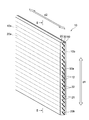
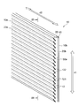
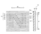
- FIG. 1 is a perspective view showing a solar cell composite display body, for explaining the first embodiment.
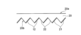
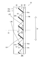
- FIG. 2 is a sectional view taken along line II-II in FIG.
- FIG. 3 is a diagram illustrating an example of a display target displayed on the solar cell composite display.
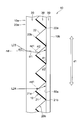
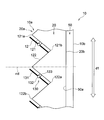
- FIG. 4 is a diagram for explaining the operation of the solar cell composite display body in the same cross section as FIG.
- FIG. 5 is a diagram for explaining the operation of the solar cell composite display body in the same cross section as FIG.
- FIG. 6 is a diagram for explaining a method for manufacturing a solar cell composite display.
- FIG. 7 is a diagram for explaining a method for manufacturing a solar cell composite display.
- FIG. 8 is a diagram for explaining a method of manufacturing a solar cell composite display.
- FIG. 1 is a perspective view showing a solar cell composite display body, for explaining the first embodiment.
- FIG. 2 is a sectional view taken along line II-II in FIG.
- FIG. 3 is a diagram illustrating an example
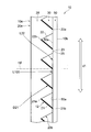
- FIG. 9 is a view corresponding to FIG. 2 and a cross-sectional view for explaining an optical path of light traveling toward the solar cell panel.
- FIG. 10 is a cross-sectional view showing a modification of the solar cell composite display shown in FIG.
- FIG. 11 is a cross-sectional view showing another modification of the solar cell composite display shown in FIG. 12 is a cross-sectional view showing still another modification of the solar cell composite display shown in FIG. 13 is a cross-sectional view showing still another modification of the solar cell composite display shown in FIG.
- FIG. 14 is a cross-sectional view showing still another modified example of the solar cell composite display shown in FIG.
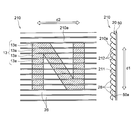
- FIG. 15 is a perspective view showing a solar cell composite display body for explaining the second embodiment.
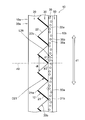
- FIG. 16 is a cross-sectional view taken along line XVI-XVI in FIG.
- FIG. 17 is a diagram illustrating an example of a display target displayed on the solar cell composite display.
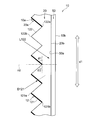
- FIG. 18 is an enlarged view of the light transmission surface shown in FIG.
- FIG. 19 is a diagram for explaining the operation of the solar cell composite display body in the same cross section as FIG.
- FIG. 20 is a diagram for explaining the operation of the solar cell composite display body in the same cross section as FIG.
- FIG. 21 is a diagram corresponding to FIG. 18 and showing an example in which the display surface is provided movably with respect to the orientation adjustment surface.
- FIG. 22 is a view corresponding to FIG.
- FIG. 16 is a cross-sectional view showing an example in which a solar cell panel is joined to a main body through a reflection loss reducing layer.
- FIG. 23 is a perspective view illustrating a panel member for explaining the third embodiment. 24 is a cross-sectional view taken along line XXIV-XXIV in FIG.
- FIG. 25 is a diagram illustrating an example of a display target displayed on the panel member.
- FIG. 26 is a view for explaining the operation of the panel member in the same cross section as FIG.
- FIG. 27 is a view for explaining the operation of the panel member in the same cross section as FIG.
- FIG. 1 to 14 are diagrams for explaining a first embodiment of the present invention.
- 1 and 2 are perspective views or longitudinal sectional views showing the configuration of the solar cell composite display body 10, and FIGS. 3 to 5 and FIG. 9 illustrate the operation of the solar cell composite display body 10.
- FIG. FIG. 6 to FIG. 8 are diagrams for explaining an example of the method for manufacturing the solar cell composite display body 10.
- the solar cell composite display 10 described here exhibits both a predetermined display function and a power generation function using external light.
- the plurality of orientation adjustment surfaces 21 and the plurality of light transmission surfaces 22 alternately arranged in the first axis direction d ⁇ b> 1 are more incident than the solar cell panel 50.
- the display surface 12 disposed mainly on the orientation adjustment surface 21 is observed. Therefore, the display surface 12 exhibits a display function for an observer who observes the solar cell composite display body 10 from a certain angle range AR1.
- the solar cell panel 50 exhibits a power generation function with respect to light incident on the solar cell composite display body 10 from another certain angular range AR2.
- the solar cell panel 50 is used when the observer observes the display surface 12 by utilizing the difference between the observation direction from the observer and the incident direction of the external light. Visibility is suppressed and it is possible to achieve harmony with the surroundings.
- the solar cell composite display body 10 includes a sheet-like main body 20 and a solar cell panel 50 disposed on the back surface of the main body 20. .
- the main body 20 forms the front surface 10 a of the solar cell composite display body 10
- the solar cell panel 50 forms the back surface 10 b of the solar cell composite display body 10.
- the surface 10 a forms an incident surface for external light such as sunlight that enters the solar cell composite display body 10.
- the surface 10 a forms an emission surface from which light from the display surface 12 that visualizes the display object 13 (see FIG. 3) is emitted from the solar cell composite display body 10.
- the sheet-like main body 20 has a first surface 20a and a second surface 20b as a pair of main surfaces facing each other.
- the first surface 20 a forms the surface 10 a of the solar cell composite display body 10
- the second surface 20 b forms a surface facing the solar cell panel 50.
- the second surface 20b of the main body 20 includes a plurality of orientation adjustment surfaces 21 and a plurality of light transmission surfaces 22 that are alternately arranged in the first axial direction d1.
- a display surface 12 for displaying the display target 13 is disposed on the orientation adjustment surface 21.
- the orientation adjusting surface 21 is provided to support the display surface 12 and adjust the viewing angle at which the display surface 12 can be observed.
- the light transmission surface 22 is provided to transmit the light L22 incident on the solar cell composite display body 10 between the adjacent display surfaces 12 and guide the light L22 to the solar cell panel 50.
- the plurality of orientation adjustment surfaces 21 are configured identically, and the plurality of light transmission surfaces 22 are also configured identically.
- a “sheet” is a concept including a member that can also be called a film or a plate.
- the “sheet surface (film surface, plate surface, panel surface)” is the plane of the target sheet-like member when the target sheet-like member is viewed as a whole and globally. A surface that matches the direction.
- the sheet surface of the main body 20, the panel surface of the solar cell panel 50, and the light receiving surface 50 a of the solar cell panel 50 are parallel to each other.
- the “normal direction” used for a sheet-like (film-like, plate-like, panel-like) member refers to a normal direction to the sheet surface of the member.
- each orientation adjusting surface 21 and each light transmitting surface 22 extend linearly in a direction intersecting the first axial direction d1 that is the arrangement direction.
- each orientation adjustment surface 21 and each light transmission surface 22 extend linearly in a second axial direction d2 that is orthogonal to both the first axial direction d1 and the normal direction nd of the main body 20. ing.
- each orientation adjusting surface 21 and each light transmitting surface 22 are arranged so as to be shifted from each other when viewed from the normal direction nd.
- the first axial direction d1 and the second axial direction d2 are along the sheet surface of the main body 20 and are orthogonal to the normal direction nd of the main body 20.
- the solar cell composite display body 10 is arranged such that the first axial direction d1 is parallel to the vertical direction and the second axial direction d2 is parallel to the horizontal direction.
- Each orientation adjusting surface 21 is inclined with respect to the sheet surface of the main body 20, in other words, the panel surface of the solar cell panel 50, and is also inclined with respect to the normal direction nd of the main body 20. That is, each orientation adjustment surface 21 is not parallel to the seat surface of the main body 20 and the normal direction nd of the main body 20.
- the first angle range AR1 can be adjusted with a high degree of freedom.
- each orientation adjustment surface 21 has one end 21 a located on one side in the first axial direction d ⁇ b> 1 (in the illustrated example, the upper side in FIG. 2 and the upper side in the vertical direction)
- the solar cell panel in the normal direction nd of the main body 20 rather than the other end 21b located on the other side in the uniaxial direction d1 (in the example shown, the lower side in FIG. 2 and the lower side in the vertical direction).
- the main body 20 is inclined with respect to the seat surface so as to be separated from the main body 20. Therefore, the one end 21 a of the orientation adjusting surface 21 is farther from the solar cell panel 50 in the normal direction nd of the main body 20 than the other end 21 b of the orientation adjusting surface 21.
- such an orientation adjusting surface 21 makes it easier for light to be emitted toward an angle range inclined to the other side with respect to the normal direction nd. Therefore, the display function from the display surface 12 disposed on the orientation adjustment surface 21 is effectively exhibited when observed from the direction D21 inclined to the other side with respect to the normal direction nd.
- the orientation adjustment surface 21 is directed from one side (upper side) to the other side (lower side) in the first axial direction d1, It is preferable to approach the solar cell panel 50 in the normal direction nd of the main body 20 stepwise or continuously.
- the orientation adjustment surface 21 is formed as a flat surface.
- the orientation adjusting surface 21 is continuously at a constant inclination from one side to the other side in the first axial direction d1.
- the solar cell panel 50 is approached along the normal direction nd of the main body 20. According to such an orientation adjustment surface 21, when the display function from the display surface 12 arranged on the orientation adjustment surface 21 is observed from a direction D21 inclined to the other side with respect to the normal direction nd, an effect is obtained. Will come into play.
- the display surface 12 for displaying the display target 13 is arranged on the orientation adjustment surface 21.
- the display surface 12 is arranged along the orientation adjustment surface 21 so as to overlap the orientation adjustment surface 21. Therefore, the light emitted from the solar cell composite display 10 toward the first angle range AR1 from the display surface 12 visualizes the display target 13 applied to the display surface 12. That is, the display surface 12 is visually recognized from the first angle range AR1, and as a result, the display target 13 formed on the display surface 12 can be observed.
- FIG. 3 shows an example of the display object 13 formed on the display surface 12.
- a plurality of display surfaces 12 are arranged in the first axial direction d1, and each display surface 12 extends linearly in a second axial direction d2 orthogonal to the first axial direction d1. Therefore, the display surface 12 located at each position in the first axial direction d1 is provided with the display target element 13a corresponding to the position of the display surface 12 in the first axial direction d1, thereby causing the display surface 12 in the second axial direction d2.
- the two-dimensional display target 13 can be displayed as a combination of the display target elements 13a formed on the elongated display surfaces 12. In the example shown in FIG. 3, the capital letter “N” of the alphabet is displayed as the display target 13.
- each orientation adjustment surface 21 can be reduced by displaying the display target 13 as a combination of a plurality of display target elements 13a, the first angle range AR1 can be expanded or the solar cell composite display body 10 can be reduced. Even if the size is increased, a better display object 13 can be observed.
- the solar cell composite display body 10 of the present embodiment can adjust the angular range in which the display target 13 is continuously displayed with a high degree of freedom. Therefore, the solar cell composite display body 10 of the present embodiment can be used for various purposes.
- the solar cell composite display body 10 has a size of several meters to several tens of meters used for outdoor signboards, road information bulletin boards, outer wall surfaces of buildings, and the like. Large panel use, medium size panel use of several tens of centimeters to several meters used for posters, signs, inner walls of buildings, etc., and small panel of several centimeters to several tens of centimeters used for table lamps, portable terminals, etc. Applications can be exemplified.
- each light transmission surface 22 located between the adjacent orientation adjustment surfaces 21 is inclined with respect to the sheet surface of the main body 20, in other words, the panel surface of the solar cell panel 50, and the normal direction of the main body 20. It is also inclined with respect to nd. That is, each orientation adjustment surface 21 is not parallel to the seat surface of the main body 20 and the normal direction nd of the main body 20.
- the second angle range AR2 that is an angle range in which power generation by the solar cell panel 50 is continuously performed stably is increased. It is possible to adjust with a degree of freedom.
- the angle at which the light transmission surface 22 is inclined with respect to the sheet surface of the main body 20 is different from the angle at which the direction adjustment surface 21 is inclined with respect to the sheet surface of the light control sheet 20.
- the light transmission surface 22 is inclined to the opposite side of the orientation adjustment surface 21 with respect to the normal direction nd of the main body 20.
- each orientation adjustment surface 21 is positioned with respect to the sheet surface of the main body 20 so that the one end 21a is separated from the solar cell panel 50 in the normal direction nd of the main body 20 than the other end 21b. It is inclined.
- each light transmission surface 22 has a second end portion 22b positioned on the other side in the first axial direction d1 and a normal direction of the main body portion 20 relative to the first end portion 22a positioned on one side in the first axial direction d1. It inclines with respect to the sheet surface of the main-body part 20 so that it may space apart from the solar cell panel 50 in nd. As can be understood from FIG. 2, light from an angle range inclined to one side with respect to the normal direction nd is easily incident on such a light transmission surface 22. Therefore, the light L22 incident on the solar cell composite display 10 from a direction inclined to one side with respect to the normal direction nd can be easily guided by the solar cell panel 50.
- the light transmission surface 22 is stepwise or continuously from the other side to the one side in the first axial direction d1
- the light transmission surface 22 is formed as a flat surface.
- the light transmission surface 22 is continuously inclined at a certain degree from the other side to the one side in the first axial direction d1.
- the solar cell panel 50 is approached along the normal direction nd of the main body 20. According to such a light transmission surface 22, the light L ⁇ b> 22 incident on the solar cell composite display body 10 from a direction inclined to one side with respect to the normal direction nd can be easily guided by the solar cell panel 50.
- the orientation adjustment surface 21 and the light transmission surface 22 will be described.
- the distance dt along the line becomes narrower stepwise or continuously as it approaches the solar cell panel 50 in the normal direction nd of the main body 20.
- the distance dt along the first axial direction d1 between each position on the orientation adjusting surface 21 and the light transmitting surface 22 adjacent to the orientation adjusting surface 21 on the other side in the first axial direction d1 is As the position on the orientation adjustment surface 21 approaches the solar cell panel 50 along the normal direction nd of the main body 20, it becomes narrower stepwise or continuously. Therefore, the other end 21b of the orientation adjusting surface 21 is closest to the one end 22a of the light transmitting surface 22 located on the other side. In the illustrated embodiment, the other end 21b of the orientation adjusting surface 21 is connected to one end 22a of the light transmitting surface 22 located on the other side. But the other end part 21b of the direction adjustment surface 21 may be spaced apart from the one end part 22a of the light transmission surface 22 located in the other side.
- one end 21a of the orientation adjustment surface 21 is connected to the other end 22b of the light transmission surface 22 adjacent to the orientation adjustment surface 21 on one side in the first axial direction d1.
- the one end portion 21a of the orientation adjustment surface 21 may be separated from the other end portion 22b of the light transmission surface 22 adjacent to the orientation adjustment surface 21 on one side in the first axial direction d1.
- the orientation adjustment surface 21 is equal to the length of the light transmission surface 22 adjacent to the orientation adjustment surface 21. Therefore, the ratio of the orientation adjustment surface 21 occupying the second surface 20 b of the main body 20 is equal to the ratio of the light transmission surface 22 occupying the second surface 20 b of the main body 20.
- the orientation adjustment surface 21 may be different from the length of the light transmission surface 22 adjacent to the orientation adjustment surface 21.
- the ratio of the orientation adjustment surface 21 to the second surface 20 b of the body portion 20 is set to the It can be made smaller than the ratio of the light transmission surface 22 to the two surfaces 20b. In this case, a relatively large amount of light tends to be easily guided to the light transmission surface 22, and as a result, more light can be contributed to the solar cell panel 50.
- the angle ⁇ ⁇ b> 1 formed by the orientation adjustment surface 21 with respect to the sheet surface of the main body 20 is equal to the angle ⁇ ⁇ b> 2 formed by the light transmission surface 22 with respect to the sheet surface of the main body 20.
- the angle ⁇ 1 formed by the orientation adjustment surface 21 with respect to the sheet surface of the main body 20 is determined according to the observation direction of the observer intended to be observed, and the light transmission surface 22 is the sheet of the main body 20.
- the angle ⁇ 2 formed with respect to the surface is determined in accordance with the incident direction of external light that is intended to be captured. Therefore, the angle ⁇ 1 formed by the orientation adjustment surface 21 with respect to the sheet surface of the main body 20 may be different from the angle ⁇ 2 formed by the light transmission surface 22 with respect to the sheet surface of the main body 20.
- each orientation adjusting surface 21 and each light transmitting surface 22 are flat surfaces. However, it is not limited to such an example, and each direction adjustment surface 21 and each light transmission surface 22 may consist of curved surfaces. As an example, each orientation adjustment surface 21 and each light transmission surface 22 may form a part of a spherical surface or a curved surface such as a lens surface. More specifically, each orientation adjusting surface 21 and each light transmitting surface 22 may be lens surfaces curved so as to be convex toward the outer side, or concave toward the inner side. A curved lens surface may be used.
- the orientation adjustment surface 21 is a curved surface
- “the orientation adjustment surface 21 is inclined with respect to the plane” means that the straight line connecting both end portions 21a and 21b of the orientation adjustment surface 21 is flat in the main cut surface shown in FIG. It means to be inclined with respect to.
- the angle ⁇ 1 formed by the orientation adjusting surface 21 with respect to the sheet surface of the main body portion 20 is such that a straight line connecting both end portions 21a and 21b of the orientation adjusting surface 21 in the main cut surface shown in FIG. This is the angle made with respect to.
- the light transmission surface 22 is a curved surface
- “the light transmission surface 22 is inclined with respect to the plane” means that both end portions 22a and 22b of the light transmission surface 22 are connected in the main cut surface shown in FIG.
- the straight line is inclined with respect to the plane.
- the angle ⁇ 2 formed by the light transmission surface 22 with respect to the sheet surface of the main body portion 20 is such that a straight line connecting both end portions 22a and 22b of the light transmission surface 22 is the sheet surface of the main body portion 20 in the main cut surface shown in FIG. This is the angle made with respect to.
- a point protruding from the second surface 20 b of the main body 20 so as to approach the solar cell panel 50 along the normal direction nd of the main body 20 is defined as the top 23.
- the top 23 is defined as a connection position between one end 22 a of one light transmission surface 22 and the other end 21 b of one orientation adjustment surface 21.
- the solar cell panel 50 is disposed so as to be in contact with the top 23 of the main body 20, and the air layer 30 is formed between the second surface 20 b of the main body 20 and the solar cell panel 50. .
- the air layer 30 is formed in a space surrounded by the orientation adjustment surface 21 of the main body 20, the light transmission surface 22 of the main body 20, and the light receiving surface 50 a of the solar cell panel 50.
- the solar cell panel 50 is not limited to the example arrange
- the main-body part 20 is not limited to the example arrange
- the solar cell panel 50 is a power generator that converts light received by the light receiving surface 50a into electric energy.
- Light L22 taken into the light transmission surface 22 from the second angle range AR2 is guided to the light receiving surface 50a of the solar cell panel 50, and this light L22 is used for power generation.
- the solar cell panel 50 extends in a planar shape so as to face each of the plurality of orientation adjustment surfaces 21 and the plurality of light transmission surfaces 22 arranged in the first axial direction d1.
- the solar cell panel 50 extends in parallel with the sheet surface of the main body 20. Therefore, in the illustrated example, the first optical functional surface 211 extends in parallel with the first axial direction d1 that is the direction in which the orientation adjusting surface 21 and the light transmitting surface 22 are arranged, and the orientation adjusting surface 21 and the light transmitting surface.
- the second axial direction d2 which is the longitudinal direction of 22 extends in parallel and spreads.
- a solar cell panel 50 various forms can be used.
- a silicon-based solar cell panel, a thin-film solar cell panel, a chalcopyrite solar cell, or the like including a flat silicon substrate made of single crystal silicon or polycrystalline silicon can be used as the solar cell panel 50.
- the main body 20 is produced by molding a transparent resin.
- hot-melt extrusion processing, injection molding, or the like can be employed.
- a plurality of orientation adjustment surfaces 21 and a plurality of light transmission surfaces 22 are alternately formed on the second surface 20 b of the main body 20 obtained.
- the display surface 12 is formed on the orientation adjustment surface 21 of the main body 20.
- the display surface 12 is formed on the orientation adjustment surface 21 of the main body 20 by inkjet printing.
- the solar cell panel 50 is disposed to face the second surface 20 b of the main body 20. Thereby, the solar cell composite display 10 is obtained.
- the solar cell composite display 10 is arranged such that the first axial direction d1 that is the arrangement direction of the orientation adjustment surface 21 and the light transmission surface 22 is along the vertical direction.
- the solar cell composite display 10 is arranged such that one side in the first axial direction d1 is along the upper side in the vertical direction and the other side in the first axial direction d1 is along the lower side in the vertical direction.
- the display surface 12 arranged on the inclined orientation adjustment surface 21 is easily visible from the front direction of the display surface 12.
- the display surface 12 is inclined to one side in the first axial direction d1 with respect to the normal direction nd of the main body portion 20, and therefore the first axial direction d1 with respect to the normal direction nd.
- the solar cell composite display 10 is observed from the directions D41, D42, and D43 inclined to the other side, the display surface 12 is easily visually recognized.
- the first angle range AR1 serving as a viewing angle at which the display surface 12 located on the orientation adjustment surface 21 is observed is It can be adjusted with a high degree of freedom. Therefore, the observer can observe the display target 13 with excellent visibility and can display the display target 13 with excellent design.
- the light transmission surface 22 inclined at a different angle from the direction adjustment surface 21 efficiently transmits the light L51, L52, and L53 incident from a direction different from the directions D41, D42, and D43 in which the direction adjustment surface 21 is easily visible. It is possible to capture.
- the light transmission surface 22 is inclined to the other side in the first axial direction d1 with respect to the normal direction nd of the main body 20, and thus the first axial direction with respect to the normal direction nd.
- Light L51, L52, and L53 incident on the solar cell composite display body 10 from a direction inclined to one side in d1 can be efficiently taken.
- the lights L51, L52, and L53 taken into the light transmission surface 22 travel through the air layer 30 and are guided to the solar cell panel 50.
- the solar cell composite display body that is guided to the solar cell panel 50 by inclining the light transmission surface 22 with respect to the normal direction nd of the main body portion 20 at an angle different from that of the orientation adjustment surface 21. 10 can be adjusted with a high degree of freedom. Therefore, in the solar cell composite-type display body 10 according to the present embodiment, sunlight that changes the incident direction according to the time zone and season is efficiently received and used for power generation in the solar cell panel 50. Is possible.
- the sheet-like main body 20 having the first surface 20a and the second surface 20b facing the first surface 20a, and the second surface 20b of the main body 20 are opposed to each other.
- the second surface 20b of the main body 20 includes a plurality of orientation adjustment surfaces 21 and a plurality of light transmission surfaces 22 arranged alternately in the first axial direction d1.
- the orientation adjusting surface 21 is inclined with respect to the panel surface of the solar cell panel 50, and the light transmitting surface 22 is inclined with respect to the panel surface of the solar cell panel 50 at an angle different from that of the orientation adjusting surface 21.
- a display surface 12 for performing display is disposed on the adjustment surface 21.
- the inclined direction adjustment surface 21 and the light transmission surface 22 are inclined with respect to the panel surface of the solar cell panel 50, the inclined direction adjustment surface 21 and the light transmission surface are inclined. 22 makes it easy to effectively use light incident from the front direction.
- the light transmission surface 22 is inclined with respect to the panel surface of the solar cell panel 50 at an angle different from that of the orientation adjustment surface 21.
- the display surface 12 arranged on the orientation adjusting surface 21 has a solar cell composite display body from directions D21 and D41 to D43 that are different from the directions in which the light L22 and L51 to L53 that are easily taken into the light transmitting surface 22 are inclined.
- the light transmitting surface 22 is incident on the solar cell composite display body 10 from a direction different from the directions D21 and D41 to D43 in which the orientation adjusting surface 21 is easily visible. Takes in L53 effectively.
- the first angle range AR1 and the second angle range AR2 that is an angle range in which power generation is continuously performed stably in the solar cell panel 50 can be adjusted with a high degree of freedom.
- the solar cell panel 50 is disposed to face the second surface 20b of the main body 20, the light receiving surface 50a of the solar cell panel 50 is not exposed to the outside. For this reason, the solar cell panel 50 can be made inconspicuous. For these reasons, according to the present embodiment, it is possible to achieve harmony with the surrounding environment and effectively achieve both the display on the display surface 12 and the power generation by the solar cell panel 50.
- the first angle range AR1 in which the display surface 12 can be observed is separated from the second angle range AR2 in which the solar cell panel 50 can be observed, that is, does not overlap.
- the orientation adjustment surface 21 is opposite to the light transmission surface 22 with respect to the normal direction nd of the main body 20 in the main cut surface shown in FIG. It is inclined to.
- the display surface 12 arranged on the orientation adjustment surface 21 is from directions D21 and D41 to D43 that are opposite to the directions in which the light L22 and L51 to L53 that are easily taken into the light transmission surface 22 are inclined.
- the orientation adjustment surface 21 is inclined with respect to the seat surface of the main body 20 so that the one end 21a is farther from the solar cell panel 50 in the normal direction nd of the main body 20 than the other end 21b.
- the light transmission surface 22 is inclined with respect to the sheet surface of the main body 20 so that the other end 22b is separated from the solar cell panel 50 in the normal direction nd of the main body 20 than the one end 22a.
- the solar cell composite display 10 is observed from the directions D21 and D41 to D43 inclined to the other side in the first axial direction d1 with respect to the normal direction nd of the main body 20, the light transmitting surface 22 is used.
- the display surface 12 arranged on the orientation adjusting surface 21 can be easily selectively observed.
- the light L22 and L51 to L53 incident on the solar cell composite display body 10 from the direction inclined to one side in the first axial direction d1 with respect to the normal direction nd of the main body 20 is more than the direction adjustment surface 21.
- the light transmission surface 22 can be guided to selection.
- the first angle range AR1 that is a viewing angle at which the display surface 12 arranged on the orientation adjustment surface 21 can be observed is the first axis with respect to the normal direction nd of the main body 20.
- the second angle range that corresponds to the direction inclined to the other side in the direction d1 and is the angle range in the incident direction to the solar cell composite display 10 that is guided to the solar cell panel 50 through the light transmission surface 22.
- AR2 corresponds to a direction inclined to one side in the first axial direction d1 with respect to the normal direction nd of the main body 20. For this reason, the first angle range AR1 and the second angle range AR2 are easily divided. In other words, the first angle range AR1 and the second angle range AR2 are difficult to overlap.
- the display function by the display surface 12 and the power generation function by the solar battery panel 50 are more effectively performed without adversely affecting each other. Will come to be.
- the first angle range AR1 serving as a viewing angle at which the display surface 12 can be observed is set in a direction inclined downward in the vertical direction, and the solar cell panel 50
- the second angle range AR2 that is the angle range in the incident direction to the solar cell composite display body 10 that is guided to is set in a direction inclined upward in the vertical direction.
- the observer can observe the display object 13 given to the display surface 12 from the first angle range AR1 in order to observe the solar cell composite display 10 while looking up upward in the vertical direction.
- the interval dt along the first axial direction d1 becomes narrower as the solar cell panel 50 is approached in the normal direction nd of the main body 20.
- the display surface 12 disposed on the orientation adjustment surface 21 blocks light that should be incident on the light transmission surface 22, or the light transmission surface 22 is disposed on the orientation adjustment surface 21. It is possible to effectively suppress the observation of the displayed display surface 12 from being interrupted.
- the display surface 12 observes the solar cell composite display body 10 from the direction within the first angle range AR1, the display function can be more reliably exhibited. Further, the light transmission surface 22 can more reliably guide the light incident on the solar cell composite display body 10 from the second angle range AR2 to the solar cell panel 50.
- the large-sized solar cell panel 50 is disposed so as to face the second surface 20 b of the main body 20.
- a small solar cell panel 50 on each light transmission surface 22 and use a large number of solar cell panels 50 as a whole.
- the large-sized solar cell panel 50 is arranged to face each light transmission surface 22. In this case, since the solar cell panel 50 can be arrange
- the sheet-like main body portion 20 having the first surface 20a and the second surface 20b facing the first surface 20a and the second surface 20b of the main body portion 20 are disposed to face each other.
- a plurality of display surfaces 12 each inclined with respect to the panel surface of the solar cell panel 50 are arranged along the uniaxial direction d1.
- a mold display 10 is provided.
- Table 1 below shows the south-high altitude (°) for each season in major cities in some countries of the world. It is preferable that the south and middle altitudes of the equinox in the major cities of the country where the use is assumed be included in the second angle range AR2. This is because there is a high possibility that it can be used effectively in that country. For example, when the country assumed to be used is Japan, the altitude from 54 ° to 56 ° may be included in the second angle range AR2. Furthermore, it is preferable that an altitude from 49 ° to 61 ° is included in the second angle range AR2, since there is a high possibility that it can be used effectively in many countries in the world.
- the second angle range AR2 includes a range from the southern middle altitude of the summer solstice to the southern middle altitude of the winter solstice in the main cities of the country assumed to be used. This is because there is a high possibility that it can be used effectively throughout the year in that country. For example, when the country assumed to be used is Japan, the altitude from 31 ° to 79 ° may be included in the second angle range AR2. Furthermore, it is preferable that an altitude of 25 ° to 84 ° is included in the second angle range AR2, since there is a high possibility that it can be used effectively in many countries in the world.
- the angle range of the second angle range AR2 is continuous by about 45 ° or more.
- the upper limit of the angle range of the second angle range AR2 may be appropriately set in balance with the first angle range AR1, but by setting it to less than about 135 °, the solar cell composite display according to the present embodiment. The features of the body 10 can be exhibited more.
- FIG. 9 an example of the optical path of the sunlight which goes to the solar cell panel 50 is shown.
- the incident angle when the light L23 intended to be incident on the light transmission surface 22 is incident on the first surface 20a of the main body 20 is ⁇ 0 (0 ° ⁇ ⁇ 0 ⁇ 90 °).
- the refraction angle at which the light L23 is refracted by the first surface 20a of the main body 20 is ⁇ 1.
- the incident angle ⁇ 0 is an angle formed by the light L23 incident on the first surface 20a with respect to the normal direction of the first surface 20a
- the refraction angle ⁇ 1 is the light L23 refracted by the first surface 20a. This is an angle formed with respect to the normal direction of the first surface 20a.
- the normal direction of the first surface 20 a coincides with the normal direction nd of the main body 20.
- the refractive index of the air layer is n0
- an incident angle when the light L23 transmitted through the first surface 20a of the main body 20 enters the light transmission surface 22 is ⁇ 2. That is, the incident angle ⁇ 2 is an angle formed by the light L23 incident on the light transmission surface 22 with respect to the normal direction nd1 of the light transmission surface 22.
- the incident angle ⁇ 2 at that time should be smaller than the total reflection critical angle at the light transmitting surface 22, n1 ⁇ SIn ⁇ 2 ⁇ n0 ⁇ 1 (2) It becomes.
- Equation (5) indicates that the incident angle ⁇ 2 when the light L24 incident on the first surface 20a of the main body 20 along the normal direction nd of the main body 20 is incident on the light transmission surface 22 is the light transmission
- the conditions when the total reflection critical angle at the surface 22 is smaller than the above are shown. Therefore, by determining the refractive index n1 of the main body 20 and the angle ⁇ 2 of the light transmission surface 22 so as to satisfy this formula (5), the first main body 20 is aligned along the normal direction nd of the main body 20.
- the light L24 incident on the surface 20a can go to the solar cell panel 50 without being totally reflected by the light transmission surface 22.
- any light incident on the first surface 20a from a direction inclined to one side in the first axial direction d1 with respect to the normal direction nd of the main body portion 20 is mainly light.
- the light transmission surface 22 can be transmitted without being totally reflected by the transmission surface 22.
- the solar cell composite display 10 is installed so that one side in the first axial direction d1 corresponds to the upper side in the vertical direction and the normal direction nd of the main body 20 corresponds to the horizontal direction. . Therefore, when Expression (5) is satisfied, it is possible to guide sunlight incident on the first surface 20a from the direction inclined upward in the vertical direction to the solar cell panel 50 without being totally reflected mainly by the light transmission surface 22. It becomes.
- FIG. 10 shows another form of the shape of the top portion 23.
- the top portion 23 is configured as a flat surface 25 along the first surface 20a, and is a position farthest from the first surface 20a along the normal direction nd of the second surface 20b. Is arranged.
- Each flat surface 25 includes the other end portion (end portion located on the solar cell panel 50 side) 21b of the orientation adjustment surface 21, and one end portion (end portion located on the solar cell panel 50 side) 21a of the light transmission surface 22. , Between these ends are connected to each other.
- the flat surface 25 is disposed along the first surface 20a of the main body 20, the light L100 incident on the first surface 20a of the main body 20 from the direction along the normal direction nd according to the flat surface 25. Can be guided to the solar cell panel 50 with high transmittance. Further, vibration or impact is transmitted to the solar cell composite display 10 during transportation or transportation, and the top 23 of the main body 20 may come into contact with the solar cell panel 50 and be damaged, but the example shown in FIG. According to this, the flat surface 25 can be in contact with the solar cell panel 50 and stably supported, thereby reducing the possibility that the top 23 is damaged.
- the reflective surface 15 may be further disposed so as to overlap the display surface 12.
- FIG. 11 shows an example in which the reflective surface 15 is placed on the display surface 12.
- the display surface 12 faces the first surface 20a, and the reflecting surface 15 faces the second surface 20b. That is, each reflecting surface 15 is disposed so as to be back-to-back with the corresponding display surface 12.
- Such a reflective surface 15 is formed by a thin film made of a material having a high reflectance as an example.
- the reflection surface 15 the light incident on the light transmission surface 22 of the main body 20 from a direction that is extremely inclined to one side (upper side in FIG. 11) in the first axial direction d 1 with respect to the normal direction nd of the main body 20. Even when the light L25 is refracted by the light transmitting surface 22 and approaches the display surface 12 from the back surface side (second surface 20b side), the light L25 is reflected by the reflecting surface 15 and directed to the solar cell panel 50. You can make it. Therefore, by providing the reflecting surface 15, the second angle range AR2 corresponding to the incident angle range of the light guided to the solar cell panel 50 can be further widened. Thereby, the sunlight which changes an incident direction according to a time zone and a season can be efficiently utilized for power generation by the solar cell panel 50.
- the diffusing element 35 may be further provided in the optical path of the light transmitted through the light transmission surface 22 toward the solar cell panel 50.
- FIG. 12 shows an example in which a diffusion layer 35 is further provided. As shown in FIG. 12, the diffusing element 35 is disposed in a region including a region between the light transmission surface 22 and the solar cell panel 50. In particular, in the example shown in FIG. 12, the diffusing element 35 forms a diffusing layer laminated on the entire light receiving surface 50 a of the solar cell panel 50.
- the diffusing element 35 includes a main portion 35a and a diffusion component 35b that scatters light dispersed in the main portion 35a.
- the diffusion component 35b here is a component that can act on the light traveling in the diffusion element 35 by changing the path direction of the light by reflection or refraction.
- a light scattering function of the diffusing component 35b can be achieved by, for example, forming the diffusing component 35b from a material having a refractive index different from that of the material forming the main portion 35a of the diffusing element 35, or Can be applied by constructing the diffusing component 35b from a material that can have a reflective effect on.
- Examples of the diffusion component 35b having a refractive index different from that of the material forming the main portion 35a include a metal compound, a porous substance containing gas, and simple bubbles.
- the light L 26 that is transmitted through the light transmitting surface 22 toward the solar cell panel 50 is diffused by the diffusing element 35.
- the light L26 diffused by the diffusing element 35 reaches a wide area of the solar cell panel 50. For this reason, the part which the solar cell panel 50 is not irradiated can be reduced, and it can suppress that the output of the solar cell panel 50 is reduced.
- FIG. 13 the other form of the solar cell composite display 10 is shown.
- the solar cell composite display body 10 is located in the valley region V between the two adjacent top portions 23 forming the second surface 20 b of the main body 20, and the valley region V It further has a low refractive index layer 38 that fills at least a portion.
- the low refractive index layer 38 covers the second surface 20b of the main body 20 and the light receiving surface 50a of the solar cell panel 50 without any gap.
- the refractive index of the low refractive index layer 38 is different from the refractive index of the main body 20. For this reason, a refractive index difference is generated at the interface between the low refractive index layer 38 and the main body 20.
- the refractive index of the low refractive index layer 38 of the present embodiment is lower than the refractive index of the main body portion 20.
- the low-refractive index layer 38 by filling at least a part of the valley region V between the two adjacent top portions 23, it is possible to increase the resistance against pressing of the main body portion 20 against the second surface 20b. .
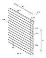
- a plurality of unit lenses 28 may be arranged on the first surface 20a of the main body 20.
- FIG. 14 shows an example in which a plurality of unit lenses 28 are further provided. As shown in FIG. 14, the plurality of unit lenses 28 are arranged such that their optical axes od are parallel to each other. In particular, in the illustrated example, the unit lens 28 is arranged so that its optical axis od is parallel to the normal direction nd of the main body 20. Further, in the example shown in FIG. 14, one orientation adjusting surface 21 and a light transmitting surface 22 are arranged to face one unit lens 28.
- the unit lens 28 constitutes a so-called lenticular lens or cylindrical lens. That is, each unit lens 28 extends linearly in a direction intersecting the first axis direction d1 that is the arrangement direction thereof. In particular, in the illustrated example, the unit lens 28 extends linearly in a second direction d2 orthogonal to both the first axial direction d1 and the normal direction nd. Further, the plurality of unit lenses 28 are configured identically to each other.
- the unit lens 28 has a convex lens-like lens surface 28a.
- the lens surface 28 a forms the surface 10 a of the solar cell composite display body 10.
- the lens surface 28a is symmetric about the optical axis od.
- Each unit lens 28 collects a parallel light beam incident on its lens surface 28a on the focal point fp.
- the focal point fp shown in FIG. 14 is a focal point for the parallel light L27 incident along the optical axis od of the unit lens 28, and is therefore located on the optical axis od of the unit lens 28.
- Second Embodiment a second embodiment will be described with reference to FIGS.
- the second embodiment described with reference to FIGS. 15 to 22 is different in that the orientation adjustment surface 121 and the light transmission surface 122 are included in the first surface 20a of the main body 20, but the other configurations are as follows. It can be configured in the same manner as the first embodiment and its modifications.
- the first embodiment described above and the parts thereof that can be configured in the same manner as in the first embodiment described above and the modifications thereof are described.
- the same reference numerals as those used for the corresponding parts in the modification are used, and redundant description is omitted.
- FIG. 16 and FIG. 18 are perspective views or longitudinal sectional views showing the configuration of the solar cell composite display body 10 in the second embodiment, and FIG. 17, FIG. 19 and FIG. It is a figure for demonstrating the effect
- the solar cell composite display 10 includes a sheet-like main body 20 and a solar cell panel 50 bonded to the second surface 20 b of the main body 20. Have.
- the first surface 20a of the main body 20 includes a plurality of orientation adjustment surfaces 121 and a plurality of light transmission surfaces 122 arranged alternately in the first axial direction d1.
- a display surface 12 for displaying the display target 13 is arranged on the orientation adjustment surface 121.
- each orientation adjusting surface 121 and each light transmitting surface 122 intersect with the first axis direction d1 that is the arrangement direction, more specifically, the first axis direction d1 and the normal line. It extends linearly in a second axial direction d2 perpendicular to both directions nd.
- each orientation adjustment surface 121 and each light transmission surface 122 are arranged so as to be shifted from each other when viewed from the normal direction nd.
- Each orientation adjusting surface 121 is inclined with respect to the sheet surface of the main body 20, in other words, the panel surface of the solar cell panel 50, and is also inclined with respect to the normal direction nd of the main body 20.
- the first angle range AR1 can be adjusted with a high degree of freedom.
- each orientation adjusting surface 121 has one end 121a located on one side in the first axial direction d1 (in the example shown, the upper side in FIG. 16 and the upper side in the vertical direction).
- the solar cell panel in the normal direction nd of the main body 20 rather than the other end 121b located on the other side in the uniaxial direction d1 (in the example shown, the lower side in FIG. 16 and the lower side in the vertical direction).
- the main body 20 is inclined with respect to the seat surface so as to be separated from the main body 20. Therefore, one end 121 a of the orientation adjustment surface 121 is farther from the solar cell panel 50 in the normal direction nd of the main body 20 than the other end 121 b of the orientation adjustment surface 121.
- such an orientation adjustment surface 121 makes it easier for light to be emitted toward an angle range inclined to the other side with respect to the normal direction nd. Therefore, the display function from the display surface 12 arranged on the orientation adjustment surface 121 is effectively exhibited when observed from the direction D21 inclined to the other side with respect to the normal direction nd.
- the orientation adjustment surface 121 is directed from one side (upper side) to the other side (lower side) in the first axial direction d1, It is preferable to approach the solar cell panel 50 in the normal direction nd of the main body 20 stepwise or continuously.
- the orientation adjustment surface 121 is formed as a flat surface.
- the orientation adjusting surface 121 is continuously inclined at a certain inclination from one side to the other side in the first axial direction d1.
- the solar cell panel 50 is approached along the normal direction nd of the main body 20. According to such an orientation adjustment surface 121, when the display function from the display surface 12 arranged on the orientation adjustment surface 121 is observed from a direction D21 inclined to the other side with respect to the normal direction nd, an effect is obtained. Will come into play.
- the display surface 12 for displaying the display target 13 is arranged on the orientation adjustment surface 121.
- the display surface 12 is arranged along the orientation adjustment surface 121 so as to overlap the orientation adjustment surface 121. Therefore, the light emitted from the solar cell composite display 10 toward the first angle range AR1 from the display surface 12 visualizes the display target 13 applied to the display surface 12.
- FIG. 17 shows an example of the display target 13 formed on the display surface 12.
- a plurality of display surfaces 12 are arranged in the first axial direction d1, and each display surface 12 extends linearly in a second axial direction d2 orthogonal to the first axial direction d1. Therefore, the display surface 12 located at each position in the first axial direction d1 is provided with the display target element 13a corresponding to the position of the display surface 12 in the first axial direction d1, thereby causing the display surface 12 in the second axial direction d2.
- the two-dimensional display target 13 can be displayed as a combination of the display target elements 13 a formed on the first optical function surfaces 211 that are elongated.
- each light transmission surface 122 positioned between the adjacent orientation adjustment surfaces 121 is inclined with respect to the sheet surface of the main body 20, in other words, the panel surface of the solar cell panel 50, and the normal direction of the main body 20. It is also inclined with respect to nd.
- the second angle range AR2 that is an angle range in which power generation by the solar cell panel 50 is continuously performed stably is increased. It is possible to adjust with a degree of freedom.
- the angle at which the light transmitting surface 122 is inclined with respect to the sheet surface of the main body 20 is different from the angle at which the orientation adjusting surface 121 is inclined with respect to the sheet surface of the light control sheet 20.
- the light transmission surface 122 is inclined to the opposite side of the orientation adjustment surface 121 with respect to the normal direction nd of the main body 20.
- each orientation adjustment surface 121 is positioned with respect to the sheet surface of the main body 20 so that the one end 121a is separated from the solar cell panel 50 in the normal direction nd of the main body 20 relative to the other end 121b. Inclined.
- each light transmission surface 122 has a normal direction of the main body portion 20 at the other end portion 122b located on the other side in the first axial direction d1 rather than the one end portion 122a located on one side in the first axial direction d1. It inclines with respect to the sheet surface of the main-body part 20 so that it may space apart from the solar cell panel 50 in nd. As can be understood from FIG. 16, light from an angle range inclined to one side with respect to the normal direction nd is easily incident on such a light transmission surface 122. Therefore, the solar cell panel 50 can easily guide the light L122 incident on the solar cell composite display body 10 from the direction inclined to one side with respect to the normal direction nd.
- the light transmission surface 122 is gradually or continuously from the other side to the one side in the first axial direction d1
- the light transmission surface 122 is formed as a flat surface.
- the light transmission surface 122 is continuously at a constant inclination from the other side to the one side in the first axial direction d1.
- the solar cell panel 50 is approached along the normal direction nd of the main body 20. According to such a light transmission surface 122, the solar cell panel 50 can easily guide the light L122 incident on the solar cell composite display 10 from a direction inclined to one side with respect to the normal direction nd.
- the light transmission surface 122 captures light incident from a wide angle range in order to guide more light to the solar cell panel 50. For this reason, depending on the incident angle of the light incident on the light transmission surface 122, the reflection loss of light increases. Therefore, in the solar cell composite display 10 according to the present embodiment, a contrivance is made to reduce the reflection loss of light on the light transmission surface 122.
- FIG. 18 shows the light transmission surface 122 in an enlarged manner.
- an antireflection layer 115 is laminated on the light transmission surface 122.
- the antireflection layer 115 includes a plurality of layers 116 to 118 stacked in order from the light transmission surface 122 side, and each of the layers 116 to 118 is another layer positioned closer to the light transmission surface 122 than the layers 116 to 118.
- the refractive index is lower than 116 and 117.
- the antireflection layer 115 includes a first layer 116, a second layer 117, and a third layer 118 that are sequentially stacked from the light transmission surface 122 side.
- the third layer 118 has a lower refractive index than the first layer 116 and the second layer 117, and the second layer 117 has a lower refractive index than the first layer 116.
- the refractive index increases as the layers 116 to 118 positioned closer to the light transmission surface 122 and the refractive index difference can be gradually changed. The reflection loss of light can be effectively reduced.
- the first layer 116 positioned close to the light transmission surface 122 is formed of a resin layer, and the second layer 117 superimposed on the first layer 116 has a refractive index higher than that of the resin forming the first layer 116.
- the third resin layer 118 may be formed of a low resin layer, and the third layer 118 overlaid on the second layer 117 may be formed of a vapor deposition layer containing an inorganic substance having a low refractive index as a main component.
- the aspect of reducing the reflection loss of light on the light transmission surface 122 is not limited to such an example.
- the antireflection layer may be a layer having a moth-eye structure including a large number of minute protrusions.
- a number of texture structures may be provided on the light transmission surface 122 to reduce light reflection loss.
- the orientation adjustment surface 121 In the main cross section of the solar cell composite display shown in FIG. 16, the first axial direction d1 of the orientation adjusting surface 121 and the light transmitting surface 122 adjacent to the orientation adjusting surface 121 on the other side in the first axial direction d1.
- the distance along the line becomes narrower stepwise or continuously as it approaches the solar cell panel 50 in the normal direction nd of the main body 20. Therefore, the other end 121b of the orientation adjustment surface 121 is closest to the one end 122a of the light transmission surface 122 located on the other side.
- the other end 121b of the orientation adjustment surface 121 is connected to one end 122a of the light transmission surface 122 located on the other side. But the other end part 121b of the direction adjustment surface 121 may be spaced apart from the one end part 122a of the light transmission surface 122 located in the other side.
- one end 121a of the orientation adjustment surface 121 is connected to the other end 122b of the light transmission surface 122 adjacent to the orientation adjustment surface 121 on one side in the first axial direction d1.
- the one end 121a of the orientation adjustment surface 121 may be separated from the other end 122b of the light transmission surface 122 adjacent to the orientation adjustment surface 121 on one side in the first axial direction d1.
- the orientation adjustment surface 121 is equal to the length of the light transmission surface 122 adjacent to the orientation adjustment surface 121. Therefore, the ratio of the orientation adjustment surface 121 occupying the first surface 20 a of the main body 20 is equal to the ratio of the light transmission surface 122 occupying the first surface 20 a of the main body 20. However, in the main cut surface shown in FIG. 16, the orientation adjustment surface 121 may be different from the length of the light transmission surface 122 adjacent to the orientation adjustment surface 121.
- the ratio of the orientation adjustment surface 121 to the first surface 20 a of the body portion 20 is set to the first portion 20 of the body portion 20.
- the ratio can be smaller than the ratio of the light transmission surface 122 to the one surface 20a. In this case, a relatively large amount of light tends to be easily guided to the light transmission surface 122, and as a result, it can contribute to guiding more light to the solar cell panel 50.
- the angle ⁇ 1 formed by the orientation adjustment surface 121 with respect to the sheet surface of the main body 20 is equal to the angle ⁇ 2 formed by the light transmission surface 122 with respect to the sheet surface of the main body 20.
- the angle ⁇ 1 formed by the orientation adjustment surface 121 with respect to the sheet surface of the main body 20 is determined according to the observation direction by the observer intended to be observed, and the light transmission surface 122 is the sheet of the main body 20.
- the angle ⁇ 2 formed with respect to the surface is determined in accordance with the incident direction of external light that is intended to be captured. Therefore, the angle ⁇ 1 formed by the orientation adjustment surface 121 with respect to the sheet surface of the main body 20 may be different from the angle ⁇ 2 formed by the light transmission surface 122 with respect to the sheet surface of the main body 20.
- each orientation adjusting surface 121 and each light transmitting surface 122 are flat surfaces. However, it is not limited to such an example, and each orientation adjustment surface 121 and each light transmission surface 122 may be formed of a curved surface.
- the solar cell composite display 10 is arranged such that the first axial direction d1 that is the arrangement direction of the orientation adjustment surface 121 and the light transmission surface 122 is along the vertical direction.
- the solar cell composite display 10 is arranged such that one side in the first axial direction d1 is along the upper side in the vertical direction and the other side in the first axial direction d1 is along the lower side in the vertical direction.
- the display surface 12 arranged on the inclined orientation adjustment surface 121 is easily visible from the front direction of the display surface 12.
- the display surface 12 is inclined to one side in the first axial direction d1 with respect to the normal direction nd of the main body portion 20, and thus the first axial direction d1 with respect to the normal direction nd.
- the solar cell composite display 10 is observed from the directions D141, D142, and D143 inclined to the other side of the display surface 12, the display surface 12 is easily visually recognized.
- the first angle range AR1 that is the viewing angle at which the display surface 12 is observed is It can be adjusted with a high degree of freedom. Therefore, the observer can observe the display target 13 with excellent visibility and can display the display target 13 with excellent design.
- the light transmission surface 122 inclined at an angle different from the direction adjustment surface 121 efficiently transmits light L151, L152, and L153 incident from a direction different from the directions D141, D142, and D143 in which the direction adjustment surface 121 is easily visible. It is possible to capture.
- the first axial direction with respect to the normal direction nd since the light transmission surface 122 is inclined to the other side in the first axial direction d1 with respect to the normal direction nd of the main body 20, the first axial direction with respect to the normal direction nd.
- Light L151, L152, and L153 incident on the solar cell composite display body 10 from a direction inclined to one side in d1 can be efficiently captured.
- the lights L151, L152, and L153 taken into the light transmission surface 122 travel through the main body 20 and are guided to the solar cell panel 50.
- the solar cell composite display body that is guided to the solar cell panel 50 by inclining the light transmission surface 122 with respect to the normal direction nd of the main body portion 20 at an angle different from that of the orientation adjustment surface 121. 10 can be adjusted with a high degree of freedom. Therefore, in the solar cell composite-type display body 10 according to the present embodiment, sunlight that changes the incident direction according to the time zone and season is efficiently received and used for power generation in the solar cell panel 50. Is possible.
- the sheet-like main body 20 having the first surface 20a and the second surface 20b facing the first surface 20a, and the second surface 20b of the main body 20 are opposed to each other.
- the first surface 20a of the main body 20 includes a plurality of orientation adjustment surfaces 121 and a plurality of light transmission surfaces 122 that are alternately arranged in the first axial direction d1.
- the orientation adjustment surface 121 is inclined with respect to the panel surface of the solar cell panel 50, and the light transmission surface 122 is inclined with respect to the panel surface of the solar cell panel 50 at an angle different from that of the orientation adjustment surface 121.
- a display surface 12 for displaying is arranged on the adjustment surface 121.
- the orientation adjustment surface 121 and the light transmission surface 122 are inclined with respect to the panel surface of the solar cell panel 50, the inclined orientation adjustment surface 121 and the light transmission surface are inclined. 122 becomes easy to use effectively the light which enters from each front direction.
- the light transmission surface 122 is inclined with respect to the panel surface of the solar cell panel 50 at an angle different from that of the orientation adjustment surface 121.
- the display surface 12 arranged on the orientation adjustment surface 121 has a solar cell composite display body from directions D121 and D141 to D143 that are different from the directions in which the light L122 and L151 to L153 that are easily taken into the light transmission surface 122 are inclined.
- the light transmitting surface 122 is incident on the solar cell composite display 10 from a direction different from the directions D 121 and D 141 to D 143 where the orientation adjusting surface 121 is easily visible. Takes in L153 effectively.
- the first angle range AR1 and the second angle range AR2 that is an angle range in which power generation is continuously performed stably in the solar cell panel 50 can be adjusted with a high degree of freedom.
- the solar cell panel 50 is disposed to face the second surface 20b of the main body 20, the light receiving surface 50a of the solar cell panel 50 is not exposed to the outside. For this reason, the solar cell panel 50 can be made inconspicuous. For these reasons, according to the present embodiment, it is possible to achieve harmony with the surrounding environment and effectively achieve both the display on the display surface 12 and the power generation by the solar cell panel 50.
- the first angle range AR1 in which the display surface 12 can be observed is separated from the second angle range AR2 in which the solar cell panel 50 can be observed, that is, does not overlap.
- the orientation adjustment surface 121 is opposite to the light transmission surface 122 with respect to the normal direction nd of the main body 20 in the main cut surface shown in FIG. It is inclined to.
- the display surface 12 arranged on the orientation adjustment surface 121 is from the directions D121 and D141 to D143 opposite to the direction in which the light L122 and L151 to L153 inclined to be easily taken into the light transmission surface 122 is inclined.
- Lights L122 and L151 to L153 incident on the battery composite display 10 can be selectively captured.
- the orientation adjustment surface 121 is inclined with respect to the seat surface of the main body 20 so that the one end 121a is farther from the solar cell panel 50 in the normal direction nd of the main body 20 than the other end 121b.
- the light transmission surface 122 is inclined with respect to the sheet surface of the main body 20 such that the other end 122b is separated from the solar cell panel 50 in the normal direction nd of the main body 20 than the one end 122a.
- the light transmitting surface 122 is used.
- the display surface 12 arranged on the orientation adjustment surface 121 can be easily observed selectively.
- the light L122 and L151 to L153 incident on the solar cell composite display body 10 from the direction inclined to one side in the first axial direction d1 with respect to the normal direction nd of the main body 20 is more than the direction adjustment surface 121.
- the light transmission surface 122 can be guided to selection.
- the first angle range AR1 that is a viewing angle at which the display surface 12 arranged on the orientation adjustment surface 121 can be observed is the first axial direction with respect to the normal direction nd of the panel member.
- the second angle range AR2 corresponding to the direction inclined to the other side in d1 and the angle range in the incident direction to the solar cell composite display 10 that is guided to the solar cell panel 50 via the light transmission surface 122.
- the first angle range AR1 and the second angle range AR2 are easily divided. In other words, the first angle range AR1 and the second angle range AR2 are difficult to overlap.
- the display function by the display surface 12 and the power generation function by the solar battery panel 50 are more effectively performed without adversely affecting each other. Will come to be.
- the first angle range AR1 serving as a viewing angle at which the display surface 12 can be observed is set in a direction inclined downward in the vertical direction, and the solar cell panel 50
- the second angle range AR2 that is the angle range in the incident direction to the solar cell composite display body 10 that is guided to is set in a direction inclined upward in the vertical direction.
- the observer can observe the display object 13 given to the display surface 12 from the first angle range AR1 in order to observe the solar cell composite display 10 while looking up upward in the vertical direction.
- the interval along the first axial direction d1 becomes narrower as the solar cell panel 50 is approached in the normal direction nd of the main body 20.
- the display surface 12 disposed on the orientation adjustment surface 121 blocks light that should enter the light transmission surface 122, or the light transmission surface 122 is disposed on the orientation adjustment surface 121. It is possible to effectively suppress the observation of the displayed display surface 12 from being interrupted.
- the display surface 12 observes the solar cell composite display body 10 from the direction within the first angle range AR1, the display function can be more reliably exhibited. Further, the light transmission surface 122 can more reliably guide the light incident on the solar cell composite display body 10 from the second angle range AR2 to the solar cell panel 50.
- the one end 121a of the orientation adjustment surface 121 is connected to the other end 122b of the light transmission surface 122 adjacent to the orientation adjustment surface 121 on one side in the first axial direction d1. .
- the light incident on the solar cell composite display body 10 is prevented from being transmitted between the one end 121a of the orientation adjustment surface 121 and the other end 122b of the light transmission surface 122.
- the light can be incident on the display surface 12 or the light transmission surface 122 arranged on the direction adjustment surface 121. As a result, the light incident on the solar cell composite display 10 can be used efficiently.
- the other end 121b of the orientation adjustment surface 121 is connected to one end 122a of the light transmission surface 122 adjacent to the orientation adjustment surface 121 on the other side in the first axial direction d1. .
- the light incident on the solar cell composite display body 10 is prevented from being transmitted between the other end 121b of the orientation adjustment surface 121 and the one end 121a of the light transmission surface 122.
- the light can be incident on the display surface 12 or the light transmission surface 122 arranged on the direction adjustment surface 121. As a result, the light incident on the solar cell composite display 10 can be used efficiently.
- the antireflection layer 15 is laminated on the light transmission surface 122, and the antireflection layer 15 includes the plurality of layers 16 to 18 stacked in order from the light transmission surface 122 side.
- the refractive indexes of 16 to 18 are lower than those of the other layers 16 and 17 located on the light transmission surface 122 side of the layers 16 to 18.
- the layers 16 to 18 positioned closer to the light transmission surface 122 have a higher refractive index and can gradually change the refractive index difference. The reflection loss of light incident on the surface 10a can be effectively reduced.
- the solar cell panel 50 is joined to the second surface 20 b of the main body 20.
- each solar cell panel 50 is arranged so as to overlap the corresponding one light transmission surface 122, a large number of solar cell panels 50 are required, resulting in an increase in cost.
- the size of each solar cell panel 50 cannot be increased so much that the power generation efficiency cannot be increased so much.
- the solar cell panel 50 is joined to the second surface 20 b of the main body 20 while facing each light transmission surface 122. In this case, since the solar cell panel 50 can be arrange
- FIG. 16 shows the example in which the display surface 12 is printed on the orientation adjustment surface 121 .
- the form in which the display surface 12 is arranged on the orientation adjustment surface 121 is such an example. It is not limited to.
- FIG. 21 shows another example in which the display surface 12 is arranged on the orientation adjustment surface 121.
- the display surface 12 is attached to the orientation adjustment surface 121 via the movable means 130 and is movable with respect to the orientation adjustment surface 121.
- the movable unit 130 includes a movable plate 131 provided to face the orientation adjustment surface 121, a fulcrum shaft 132 that holds the movable plate 131, and the fulcrum shaft that extends from the orientation adjustment surface 121 to the fulcrum shaft 132. And a column 133 that rotatably supports 132.
- the display surface 12 provided with the display target 13 is formed on the surface of the movable plate 131 that faces away from the orientation adjustment surface 121.
- a motor (not shown) that drives the fulcrum shaft 132 is attached to the fulcrum shaft 132.
- the orientation of the movable plate 131 can be adjusted by rotating the fulcrum shaft 132 by a motor (not shown) according to the direction in which the observer observes the display surface 12.
- the orientation of the display surface 12 disposed on the movable plate 131 can be adjusted to the direction in which the observer observes the display surface 12, and the viewing angle at which the display object 13 given to the display surface 12 can be observed.
- the first angle range AR1 can be adjusted with a high degree of freedom and can be widened.
- the solar cell panel 50 is joined to the main body 20 as shown in FIG.
- the layer 160 which joins this solar cell panel 50 to the main-body part 20 is demonstrated in detail with reference to FIG.
- FIG. 22 shows an example in which the solar cell panel 50 is joined to the main body 20 via a layer 160 made of resin.
- a layer 160 shown in FIG. 22 is configured as a reflection loss reducing layer, and efficiently receives sunlight L122 to L124 taken from the light transmission surface 122 by the solar cell panel 50, and the main body 20 and the solar cell panel 50. Has the function of joining.
- the reflection loss reducing layer 160 is formed between the second surface 20 b of the main body 20 and the light receiving surface 50 a of the solar cell panel 50, and between the second surface 20 b of the main body 20 and the solar cell panel 50. Adjacent to the light receiving surface 50a.
- the reflection loss reducing layer 160 shown in FIG. 22 covers the entire second surface 20b of the main body 20 and the entire light receiving surface 50a of the solar cell panel 50 without any gaps.
- the reflection loss reducing layer 160 can be made of various polymer resin materials known per se.
- the material forming the reflection loss reducing layer 160 is preferably made of a material having excellent light transmittance.
- the material which comprises the reflection loss reduction layer 160 is adhesiveness with the material which comprises the main-body part 20, and the material which comprises the solar cell panel 50. It should be made of an excellent material.
- the reflection loss reducing layer 160 may be a single layer or a multilayer.
- the surface of the light receiving surface 50a of the solar cell panel 50 is joined by joining the light receiving surface 50a of the solar cell panel 50 to the second surface 20b of the main body 20 via the reflection loss reducing layer 160. It is difficult to form an air layer. If an air layer is formed on the surface of the light receiving surface 50 a of the solar cell panel 50, the light L122 to L124 that is about to enter the light receiving surface 50 a of the solar cell panel 50 is transmitted to the air layer and the second surface 20 b of the main body 20. There is an increased risk that the light will be totally reflected at the interface, and the light L122 to L124 cannot be efficiently used in the solar cell panel 50. On the other hand, according to the embodiment shown in FIG. 22, it is difficult to form an air layer on the surface of the light receiving surface 50 a of the solar cell panel 50. The light receiving surface 50a can be taken in with high efficiency.
- a position of the first surface 20a of the main body 20 that protrudes away from the second surface 20b along the normal direction nd of the main body 20 is defined as a top 123, and the first surface 20a of the main body 20 is formed.
- a position that is recessed so as to approach the second surface 20 b along the normal direction nd of the main body portion 20 is defined as a trough portion 124.
- the top portion 123 is defined as a connection position between the other end portion 122 b of the one light transmission surface 122 and the one end portion 121 a of the one orientation adjustment surface 121, and the trough portion 124 is the other light transmission surface 122. It is defined as a connection position between the end portion 122b and one end portion 122a of one orientation adjusting surface 121.
- light incident on each position of the light transmission surface 122 from the direction most inclined to one side with respect to the normal direction nd of the main body portion 20 is incident on one side of the light transmission surface 122.
- the lights L123 and L124 passing through the top 123 here are lights that pass through the top 123 while maintaining the traveling direction so as to be in contact with the top 123.
- the light L123 and L124 that have entered the light transmission surface 122 through the top portion 123 pass through the refractive index adjustment layer 60 from the direction most inclined to one side with respect to the normal direction nd to the main body portion 20.
- the light is light that is not blocked by the valley portion 124, that is, light L124 that passes through the valley portion 124.
- the light L123 passing through the valley 124 is light that passes through the valley 124 while maintaining the traveling direction so as to be in contact with the valley 124.
- the light L123 is incident on the light transmission surface 122 from the direction most inclined to the one side with respect to the normal direction nd to the main body portion 20, and is not blocked by the valley portion 124.
- the interface between the main body portion 20 and the reflection loss reduction layer 160 and the reflection loss reduction are reduced. Passes at least through the interface between the layer 160 and the solar panel 50.
- the reflection loss reducing layer 160 covers the light receiving surface 50a of the solar cell panel 50 without a gap, it is difficult for an air layer to intervene between the reflection loss reducing layer 160 and the light receiving surface 50a. The reflection loss at the interface between the reduction layer 160 and the light receiving surface 50a is reduced.
- the light L123 can be transmitted through the reflection loss reduction layer 160 without being totally reflected at the interface between the main body 20 and the reflection loss reduction layer 160, the light L123 is incident on the light receiving surface 50a of the solar cell panel 50. It is thought that more light can be captured.
- the condition that the light L123 is not totally reflected at the interface between the main body 20 and the reflection loss reducing layer 160 will be described.
- the incident angle when the light L123 is incident on the light transmission surface 122 is ⁇ 10, and the refraction angle at which the light L123 is refracted by the light transmission surface 122 is ⁇ 11. That is, the incident angle ⁇ 10 is an angle formed by the light L123 incident on the light transmission surface 122 with respect to the normal direction nd1 of the light transmission surface 122, and the refraction angle ⁇ 11 is the light L123 refracted by the light transmission surface 122. , An angle formed with respect to the normal direction nd1 of the light transmission surface 122.
- the refractive index of the layer adjacent to the first surface 20a of the main body 20 is n10, and the refractive index of the main body 20 is n11.
- the incident angle when the light L123 enters the reflection loss reducing layer 160 is ⁇ 12. That is, the incident angle ⁇ 12 is an angle formed by the light L123 incident on the reflection loss reducing layer 160 with respect to the normal direction nd2 of the reflection loss reducing layer 160.
- the normal direction nd2 of the reflection loss reducing layer 160 is parallel to the normal direction nd of the main body 20.
- the refractive index of the reflection loss reducing layer 160 is n12.
- the incident angle ⁇ 12 when the light L123 enters the reflection loss reducing layer 160 is reflected by the main body 20 and the reflection loss reducing layer 160. Since it should be smaller than the total reflection critical angle at the interface with the loss reduction layer 160, n11 ⁇ SIn ⁇ 12 ⁇ n12 ⁇ 1 (12) It becomes.
- the light L123 is reflected so as not to be totally reflected at the interface between the main body 20 and the reflection loss reducing layer 160.
- the loss reduction layer 160 can be selected. Therefore, by determining the refractive index n12 so as to satisfy Expression (12), a large amount of light L122 to L124 incident on the solar cell composite display 10 from the light transmitting surface 122 is received by the light receiving surface 50a of the solar cell panel 50. Can be captured.
- the reflection loss reduction layer 160 is further provided between the second surface 20 b of the main body 20 and the light receiving surface 50 a of the solar cell panel 50, thereby reducing reflection loss.
- the layer 160 joins the second surface 20 b of the main body 20 and the light receiving surface 50 a of the solar cell panel 50. According to such a form, since the light receiving surface 50a of the solar cell panel 50 is joined to the second surface 20b of the main body 20 via the reflection loss reducing layer 160, the surface of the light receiving surface 50a of the solar cell panel 50 is bonded. It is difficult to form an air layer.
- the reflection loss reducing layer 160 covers the light receiving surface 50a of the solar cell panel 50 without a gap.
- the possibility that an air layer is formed between the reflection loss reducing layer 160 and the light receiving surface 50a of the solar cell panel 50 can be remarkably reduced, the sunlight L122 taken in from the light transmitting surface 122 is converted into the sun. It becomes possible to take in with high efficiency at the light receiving surface 50a of the battery panel 50.
- the main body portion is defined by one orientation adjustment surface 121 p and one light transmission surface 122 p in a cross section parallel to both the uniaxial direction d1 and the normal direction nd of the main body portion 20. 20 of the light L123 incident on another light transmitting surface 122q adjacent to the one orientation adjusting surface 121p through the one top portion 123 protruding so as to be separated from the second surface 20b.
- the incident angle ⁇ 2 when the light L123 passing through the portion 124 enters the reflection loss reducing layer 160 is smaller than the total reflection critical angle at the interface between the main body portion 20 and the reflection loss reducing layer 160.
- a large amount of light L122 to L124 incident from the light transmission surface 122 passes through the reflection loss reduction layer 160 without being totally reflected at the interface between the main body 20 and the reflection loss reduction layer 160. be able to. Therefore, the sunlight L122 to L124 captured from the light transmission surface 122 can be captured with higher efficiency on the light receiving surface 50a of the solar cell panel 50.
- the relationship between the main-body part 20 and the solar cell panel 50 is not limited to the example shown in FIG.
- the solar cell panel 50 may be separated from the second surface 20 b of the main body 20.
- FIGS. 23 and 24 are perspective views or longitudinal sectional views showing the panel member 210
- FIGS. 25 to 27 are diagrams for explaining an optical function that the panel member 210 develops.
- the panel member 210 includes a sheet-like main body 20 and a solar cell panel 50 disposed to face the second surface 20 b of the main body 20. .
- a plurality of unit lenses 28 are arranged on the first surface 20a of the main body 20 in the first axial direction d1.
- the plurality of unit lenses 28 are arranged such that their optical axes od are parallel to each other.
- the unit lens 28 is arranged so that its optical axis od is parallel to the normal direction nd of the panel member 210.
- the first axial direction d1 is along the panel surface of the panel member 210, and is orthogonal to the normal direction nd of the panel member 210.
- the unit lens 28 constitutes a so-called lenticular lens or cylindrical lens. That is, each unit lens 28 extends linearly in a direction intersecting the first axis direction d1 that is the arrangement direction thereof. In particular, in the illustrated example, the unit lens 28 extends linearly in a second direction d2 orthogonal to both the first axial direction d1 and the normal direction nd. Further, the plurality of unit lenses 28 are configured identically to each other.
- the unit lens 28 has a convex lens-like lens surface 28a.
- the lens surface 28 a forms the surface 210 a of the panel member 210.
- the lens surface 28a is symmetric about the optical axis od.
- Each unit lens 28 collects a parallel light beam incident on its lens surface 28a on the focal point fp.
- the focal point fp shown in FIG. 24 is a focal point for the parallel light L221 incident along the optical axis od of the unit lens 28, and is therefore located on the optical axis od of the unit lens 28.
- the first optical functional surface 211 is disposed on the second surface 20 b of the main body 20, and a plurality of second optical functional surfaces 212 are disposed inside the main body 20.
- the optical function surfaces 211 and 212 are flat surfaces or curved surfaces having a function utilizing the action and properties of light, or surfaces combining these.
- Light means not only visible light but also infrared rays to ultraviolet rays.
- Examples of the action and properties of light include straight light propagation, refraction, reflection, absorption, light emission, interference, and polarization.
- Examples of the optical function include a display function, an illumination function, a light shielding function, and an optical connection function with a solar cell, an optical element, an optical member, or an optical device.
- the first optical functional surface 211 functions as a light incident surface 50 a to the solar cell panel 50.
- the 2nd optical function surface 212 has comprised the display surface for displaying the display target 13, as an example.
- Examples of the display target 13 include patterns (images) such as figures, patterns, designs, colors, pictures, photographs, and characters, and information such as letters, marks, and numbers.
- the display target 13 may be stationary or moving. However, it is not limited to such an example, The optical function by the 1st optical function surface 211 and the optical function by the 2nd optical function surface 212 can be changed suitably.
- the first optical functional surface 211 extends in a planar shape so as to face the plurality of unit lenses 28 arranged in the first axial direction d1.
- the first optical functional surface 211 extends in parallel with the panel surface of the panel member 210.
- the first optical functional surface 211 extends in parallel with the first axis direction d1 that is the arrangement direction of the unit lenses 28, and is also parallel to the second direction d2 that is the longitudinal direction of the unit lenses 28. Extends to.
- the second optical functional surface 212 is located between the unit lens 28 and the first optical functional surface 211 in the normal direction nd of the panel member 210.
- the second optical functional surface 212 is arranged in the first axial direction d1 corresponding to the unit lens 28, which is the arrangement direction of the unit lenses 28.
- Each second optical functional surface 212 is positioned to face one unit lens 28 to which the second optical functional surface 212 corresponds.
- each second optical functional surface 212 is disposed so as to face at least partially the corresponding unit lens 28 along the normal direction nd.
- the second optical functional surface 212 is a second direction orthogonal to the first axial direction d1 in a direction that intersects the first axial direction d1 that is the arrangement direction. It extends linearly in the direction d2.
- Each second optical functional surface 212 is inclined with respect to the first optical functional surface 211.
- the normal line of the second optical function surface 212 and the normal line of the first optical function surface 211 form an angle greater than 0 ° and less than 90 ° on the main cut surface.
- Each second optical function surface 212 is inclined with respect to a direction orthogonal to the optical axis od of the unit lens 28.
- the second angle range AR2 that is an angle range in which the optical function from the second optical function surface 212 is expressed can be obtained with a high degree of freedom.
- the first angle range AR1 that is an angle range in which the optical function from the first optical function surface 211 is expressed can be adjusted with a high degree of freedom.
- FIG. 25 shows an example of the display target 13 formed on the second optical function surface 212.
- a plurality of second optical functional surfaces 212 are arranged in the first axial direction d1, and each second optical functional surface 212 extends linearly in a second direction d2 orthogonal to the first axial direction d1. Therefore, the second optical functional surface 212 located at each position in the first axial direction d1 is provided with the display target element 13a corresponding to the position of the second optical functional surface 212 in the first axial direction d1,
- the two-dimensional display target 13 can be displayed as a combination of the display target elements 13a formed on the second optical function surfaces 212 that are elongated in the second direction d2.
- the capital letter “N” of the alphabet is displayed as the display target 13.
- the panel member 210 is arrange
- the first end 212a located on one side of the second optical functional surface 212 in the first axial direction d1 is located on the upper side in the vertical direction, and the other side of the second optical functional surface 212 in the first axial direction d1.
- the panel member 210 is disposed so that the second end portion 212b located at the lower side is located on the lower side in the vertical direction.
- a plurality of unit lenses 28 are provided on the most observer side of the panel member 210.
- the unit lens 28 exhibits a lens function with respect to light incident on the panel member 210 or light emitted from the panel member 210, and adjusts the traveling direction of the light.
- the unit lens 28 guides light incident from a direction within a certain angle range AR1 to the first optical function surface 211, and guides light incident from a direction within another certain angle range AR2 to the second optical function surface 212. .
- the unit lens 28 refracts the light from the first optical function surface 211 and emits the light in the direction within the first angle range AR1, and refracts the light from the second optical function surface 212 to the second angle range.
- the light is emitted in the direction within AR2.
- the first optical function surface 211 has some optical function for light incident on the panel member 210 from the first angle range AR1 or for light emitted from the panel member 210 toward the first angle range AR1. Can be demonstrated.
- the second optical function surface 212 has some optical function for light incident on the panel member 210 from the second angle range AR2 or for light emitted from the panel member 210 toward the second angle range AR2. Can be demonstrated.
- the first optical functional surface 211 forms the light incident surface 50a of the solar cell panel 50. Therefore, it is preferable to guide light incident from a wide angle range to the first optical functional surface 211 and use it for power generation in the solar cell panel 50.
- sunlight changes its position according to the time zone and season.
- the panel member 210 it is preferable if the sunlight that changes the incident direction according to the time zone and the season can be guided to the first optical functional surface 211. That is, when taking in sunlight that changes the incident direction with high efficiency, it is preferable that the first angle range AR1 described above is widened.
- the second optical functional surface 212 is a display surface on which the display target 13 is formed. Therefore, the display object 13 formed on the second optical function surface 212 can be observed from the second angle range AR2.
- the second angle range AR2 is a viewing angle at which the display target 13 can be observed.
- the second angle range AR2 that is a viewing angle is widened.
- the viewing angle of the second angle range AR2 is about 45 ° or more. Note that the upper limit of the viewing angle of the second angle range AR2 may be set as appropriate in balance with the first angle range AR1, but it is considered that there are many cases where it is less than about 135 °.
- the panel member 210 includes the unit lenses 28 arranged in the first axial direction d1, the first optical functional surface 211 positioned facing the plurality of unit lenses, And a second optical functional surface 212 that is arranged in the uniaxial direction d1 and that faces the unit lens 28.
- the second optical functional surface 212 is located between the unit lens 28 and the first optical functional surface 211 in the normal direction nd of the panel member, and is inclined with respect to the first optical functional surface 211.
- the second optical functional surface 212 is inclined and spreads with respect to the direction orthogonal to the optical axis od of the unit lens 28.
- the first optical function surface 211 extends in a direction orthogonal to the optical axis od of the unit lens 28.
- the inclined second optical functional surface 212 can efficiently receive light L242, L243, and L244 incident from an oblique direction. Become. In particular, as shown in FIG. 26, the light L244 traveling in a direction greatly inclined with respect to the normal direction nd is also received by the second optical functional surface 212 facing the incident unit lens 28. As indicated by a dotted line in FIG. 26, if the second optical functional surface 212 is arranged on the same plane as the first optical functional surface 211, the light L244 is transmitted to a unit lens different from the incident unit lens 28. Proceed to the facing area and cause a problem.
- the second optical range AR2 which is the angular range in the incident direction to the panel member 210 that is guided to the second optical functional surface 212, in other words, the second optical functional surface 212
- the second angle range AR2 that is the angle range of the light exiting direction from the functional surface 212 can be adjusted with a high degree of freedom, and in particular, the angle can be remarkably widened. Further, the adjustment or widening of the second angle range AR2 does not require the use of a high-refractive index material that is generally expensive for the unit lens 28, and a material similar to the conventional one may be used. That is, the adjustment and widening of the second angle range AR2 can be realized without increasing the cost from the material side.
- the optical function from the second optical function surface 212 is exhibited within the wide second angle range AR2.
- panel member 210 according to the present embodiment it is possible to observe pattern 13 applied to second optical function surface 212 stably from a wide viewing angle. Therefore, the observer can observe the display target 13 with excellent visibility and can display the display target 13 with excellent design.
- the second optical functional surface 212 is located between the unit lens 28 and the first optical functional surface 211 along the normal direction nd of the panel member.
- the first optical functional surface 211 is also disposed at a position on the side opposite to the unit lens 28 of the inclined second optical functional surface 212.
- the first optical functional surface 211 extends and spreads over the entire region facing the unit lens 28 along the normal direction nd of the panel member.
- the first optical functional surface 211 that spreads over a wide range can receive light incident on the panel member 210 from a wide angle range.
- the first optical functional surface 211 located behind the inclined second optical functional surface 212 is light L242, L243, L244 (light that is efficiently received by the second optical functional surface 212).
- Light L252, L253, L254, and L255 inclined to the opposite side to that shown in FIG. 26 can be efficiently received. That is, it is possible to efficiently receive the light L252, L253, L254, and L255 incident on the panel member 210 while proceeding downward in the vertical direction. Therefore, according to the present embodiment, as shown in FIG. 27, the light L254 that travels to a region facing a unit lens different from the incident unit lens 28 is also effective on the first optical function surface 211. It can receive light.
- the first angle range AR1 that is the angle range in other words, the first angle range AR1 that is the angle range of the light emission direction from the first optical functional surface 211 can be adjusted with a high degree of freedom. Wide angle can be achieved. Further, the adjustment or widening of the first angle range AR1 does not require the use of the unit lens 28 as a high-refractive index material that is generally expensive, and a material similar to the conventional one may be used. In other words, the adjustment and widening of the first angle range AR1 can be realized without increasing the cost from the material side.
- the optical function from the first optical function surface 211 is exhibited within the wide first angle range AR1.
- panel member 210 according to the present embodiment sunlight that changes the incident direction according to the time zone and season can be efficiently received and used for power generation in solar cell panel 50.
- the second optical functional surface 212 is one side in the first axial direction d1 (in the example shown, the upper side in FIG. 24 and the upper side in the vertical direction).
- the first axial direction d1 in the example shown, the upper side in FIG. 24 and the upper side in the vertical direction.
- the other side in the first axial direction d1 in the illustrated example, the lower side in FIG. The lower side in the vertical direction
- the first optical functional surface 211 along the normal direction nd of the panel member.
- the second optical functional surface 212 has a first end 212a located on one side in the first axial direction d1 and a second end 212b located on the other side in the first axial direction d1. Also, the panel member 210 is inclined with respect to the first optical functional surface 211 so as to be close to the unit lens 28 in the normal direction nd of the panel member 210.
- light L222, L251 to L254 from a direction inclined to one side in the first axial direction d1 with respect to the normal direction nd of the panel member in other words, in the first axial direction d1.
- Lights L222 and L251 to L254 that enter the panel member 210 while proceeding to the other side along the same easily enter the first optical function surface 211.
- the light L222, L251 to L254 from the first optical function surface 211 is easily emitted in a direction inclined to one side in the first axial direction d1 with respect to the normal direction nd of the panel member.
- light L223, L241 to L244 from a direction inclined to the other side in the first axial direction d1 with respect to the normal direction nd of the panel member in other words, the panel member while proceeding to one side along the first axial direction d1.
- Lights L223 and L241 to L244 incident on 210 are likely to enter the second optical function surface 212.
- the lights L223 and L241 to L244 from the second optical function surface 212 are easily emitted in a direction inclined to the other side in the first axial direction d1 with respect to the normal direction nd of the panel member.
- the first angular range AR1 that is an angular range in the direction in which the optical function from the first optical functional surface 211 is exhibited, and the optical function from the second optical functional surface 212 are provided.
- the second angle range AR2, which is the angle range in the direction in which it is exhibited, is easily distinguished.
- the first angle range AR1 and the second angle range AR2 are difficult to overlap. Thereby, each of the first angle range AR1 and the second angle range AR2 can be effectively widened.
- the first angle range AR1 is taken in the direction inclined upward in the vertical direction
- the second angle range AR2 is taken in the direction inclined downward in the vertical direction, so that sunlight The light reception and the display of the display object 13 can be effectively made compatible.
- the first optical functional surface 211 is located on the focal point fp of the unit lens 28. More precisely, the first optical function surface 211 is located on a virtual surface defined by the focal points fp of a large number of unit lenses 28 included in the lens unit 25. Then, in the main cutting surface of the panel member shown in FIG. 24, the second end 212b located on the other side (lower side) of the second optical functional surface 212 in the first axial direction d1 is the first optical functional surface. 211 is connected. That is, in the illustrated embodiment, the second end 212b of the second optical functional surface 212 is located on the focal point fp of the unit lens 28 in the main cutting surface of the panel member.
- the first angle range AR1 and the second angle range AR2 are defined with the incident direction to the panel member 210 of the light connecting the focal point fp where the second end 212b is positioned as a boundary. Can be separated.
- the second end portion 212b located on the other side (lower side) of the second optical functional surface 212 in the first axial direction d1 on the main cutting surface of the panel member is
- the parallel light beams L21, L41, and L51 traveling in the normal direction nd are positioned on the focal position fp of the unit lens 28 when entering the unit lens 28. According to such a panel member 210, it is possible to separate the first angle range AR1 and the second angle range AR2 with the normal direction nd of the panel member as a boundary.
- the first optical functional surface is obtained.
- the optical function at 211 and the optical function at the second optical function surface 212 are more effectively exhibited without adversely affecting each other.
- the second optical functional surface 212 is located between the unit lens 28 and the first optical functional surface 211 in the normal direction nd of the panel member, and is inclined with respect to the first optical functional surface 211.
- the optical function at the first angle range AR1 and the second optical function surface 212 which are the angle ranges in the direction in which the optical function at the first optical function surface 211 is exhibited, is exhibited.
- the second angle range AR2 that is the angle range of the direction with a high degree of freedom.
- the first angle range AR1 and the second angle range AR2 can be effectively widened.
- the adjustment or widening of the first angle range AR1 and the second angle range AR2 does not require the use of a high-refractive index material, which is generally expensive, for the unit lens 28, and the same material as the conventional one is used. That's fine. That is, the first angle range AR1 and the second angle range AR2 can be adjusted or widened without increasing the cost from the material surface.
Landscapes
- Physics & Mathematics (AREA)
- General Physics & Mathematics (AREA)
- Engineering & Computer Science (AREA)
- Condensed Matter Physics & Semiconductors (AREA)
- Electromagnetism (AREA)
- Computer Hardware Design (AREA)
- Microelectronics & Electronic Packaging (AREA)
- Power Engineering (AREA)
- Theoretical Computer Science (AREA)
- Life Sciences & Earth Sciences (AREA)
- Sustainable Development (AREA)
- Road Signs Or Road Markings (AREA)
Abstract
Un dispositif d'indication du type combiné à une cellule solaire (10) comprend une partie de corps principal en forme de feuille (20) ayant une première surface (20a) et une seconde surface (20b) faisant face à la première surface (20a), et un panneau de cellules solaires (50) disposé en face de la seconde surface (20b) de la partie de corps principal (20). La seconde surface (20b) de la partie de corps principal (20) comprend une pluralité de surfaces de réglage de direction (21) et une pluralité de surfaces de transmission de lumière (22), les surfaces (21) et (22) étant disposées en alternance dans une première direction axiale (d1). Les surfaces de réglage de direction (21) et les surfaces de transmission de lumière (22) s'inclinent selon des angles différents les uns des autres par rapport à la surface de panneau du panneau de cellules solaires (50). Une surface d'indication (12) pour réaliser une indication est agencée sur chacune des surfaces de réglage de direction (21).
Applications Claiming Priority (8)
| Application Number | Priority Date | Filing Date | Title |
|---|---|---|---|
| JP2014-075571 | 2014-04-01 | ||
| JP2014075571 | 2014-04-01 | ||
| JP2014-144927 | 2014-07-15 | ||
| JP2014144927A JP6365044B2 (ja) | 2014-04-01 | 2014-07-15 | 太陽電池複合型表示体 |
| JP2014146910 | 2014-07-17 | ||
| JP2014-146910 | 2014-07-17 | ||
| JP2015-053742 | 2015-03-17 | ||
| JP2015053742A JP6488789B2 (ja) | 2014-07-17 | 2015-03-17 | 太陽電池複合型表示体 |
Publications (1)
| Publication Number | Publication Date |
|---|---|
| WO2015151819A1 true WO2015151819A1 (fr) | 2015-10-08 |
Family
ID=54240150
Family Applications (1)
| Application Number | Title | Priority Date | Filing Date |
|---|---|---|---|
| PCT/JP2015/058121 WO2015151819A1 (fr) | 2014-04-01 | 2015-03-18 | Dispositif d'indication du type combiné à une cellule solaire et élément de panneau |
Country Status (1)
| Country | Link |
|---|---|
| WO (1) | WO2015151819A1 (fr) |
Cited By (8)
| Publication number | Priority date | Publication date | Assignee | Title |
|---|---|---|---|---|
| JP2015210440A (ja) * | 2014-04-28 | 2015-11-24 | 大日本印刷株式会社 | 太陽電池パネル付き表示体 |
| JP2015210439A (ja) * | 2014-04-28 | 2015-11-24 | 大日本印刷株式会社 | 太陽電池パネル付き表示体 |
| JP2017181966A (ja) * | 2016-03-31 | 2017-10-05 | 大日本印刷株式会社 | 太陽電池複合型表示体 |
| JP2017184576A (ja) * | 2016-03-31 | 2017-10-05 | 大日本印刷株式会社 | 太陽電池複合型表示体 |
| JP2017184578A (ja) * | 2016-03-31 | 2017-10-05 | 大日本印刷株式会社 | 太陽電池複合型表示体 |
| EP3599647A1 (fr) * | 2018-07-27 | 2020-01-29 | (CNBM) Bengbu Design & Research Institute for Glass Industry Co., Ltd. | Module solaire pourvu de plaque de couverture structurée et de couche d'interférence optique |
| EP3599649A1 (fr) * | 2018-07-27 | 2020-01-29 | (CNBM) Bengbu Design & Research Institute for Glass Industry Co., Ltd. | Module solaire pourvu de plaque de couverture structurée et de couche d'interférence optique |
| EP4027188A1 (fr) * | 2021-01-12 | 2022-07-13 | Martin-Luther-Universität Halle-Wittenberg | Source de rayonnement thz à bande étroite, son émetteur et procédé de manufacture d'un émetteur |
Citations (4)
| Publication number | Priority date | Publication date | Assignee | Title |
|---|---|---|---|---|
| US5303525A (en) * | 1990-05-18 | 1994-04-19 | University Of Arkanas | Siding or roofing exterior panels for controlled solar heating |
| JP2007086656A (ja) * | 2005-09-26 | 2007-04-05 | Rinkusu:Kk | 広告表示体及びその製造方法 |
| JP2009524794A (ja) * | 2006-01-26 | 2009-07-02 | サン−ゴバン グラス フランス | ソーラーパネルの表面上に画像を表示するための光学システム |
| JP2010192468A (ja) * | 2007-11-14 | 2010-09-02 | Keisuke Mizogami | 装飾具及び太陽光受光モジュール |
-
2015
- 2015-03-18 WO PCT/JP2015/058121 patent/WO2015151819A1/fr active Application Filing
Patent Citations (4)
| Publication number | Priority date | Publication date | Assignee | Title |
|---|---|---|---|---|
| US5303525A (en) * | 1990-05-18 | 1994-04-19 | University Of Arkanas | Siding or roofing exterior panels for controlled solar heating |
| JP2007086656A (ja) * | 2005-09-26 | 2007-04-05 | Rinkusu:Kk | 広告表示体及びその製造方法 |
| JP2009524794A (ja) * | 2006-01-26 | 2009-07-02 | サン−ゴバン グラス フランス | ソーラーパネルの表面上に画像を表示するための光学システム |
| JP2010192468A (ja) * | 2007-11-14 | 2010-09-02 | Keisuke Mizogami | 装飾具及び太陽光受光モジュール |
Cited By (8)
| Publication number | Priority date | Publication date | Assignee | Title |
|---|---|---|---|---|
| JP2015210440A (ja) * | 2014-04-28 | 2015-11-24 | 大日本印刷株式会社 | 太陽電池パネル付き表示体 |
| JP2015210439A (ja) * | 2014-04-28 | 2015-11-24 | 大日本印刷株式会社 | 太陽電池パネル付き表示体 |
| JP2017181966A (ja) * | 2016-03-31 | 2017-10-05 | 大日本印刷株式会社 | 太陽電池複合型表示体 |
| JP2017184576A (ja) * | 2016-03-31 | 2017-10-05 | 大日本印刷株式会社 | 太陽電池複合型表示体 |
| JP2017184578A (ja) * | 2016-03-31 | 2017-10-05 | 大日本印刷株式会社 | 太陽電池複合型表示体 |
| EP3599647A1 (fr) * | 2018-07-27 | 2020-01-29 | (CNBM) Bengbu Design & Research Institute for Glass Industry Co., Ltd. | Module solaire pourvu de plaque de couverture structurée et de couche d'interférence optique |
| EP3599649A1 (fr) * | 2018-07-27 | 2020-01-29 | (CNBM) Bengbu Design & Research Institute for Glass Industry Co., Ltd. | Module solaire pourvu de plaque de couverture structurée et de couche d'interférence optique |
| EP4027188A1 (fr) * | 2021-01-12 | 2022-07-13 | Martin-Luther-Universität Halle-Wittenberg | Source de rayonnement thz à bande étroite, son émetteur et procédé de manufacture d'un émetteur |
Similar Documents
| Publication | Publication Date | Title |
|---|---|---|
| WO2015151819A1 (fr) | Dispositif d'indication du type combiné à une cellule solaire et élément de panneau | |
| JP6663578B2 (ja) | 太陽電池複合型表示体 | |
| US20130033873A1 (en) | Optical device and illuminating device | |
| JP6331478B2 (ja) | 太陽電池複合体 | |
| US8240904B2 (en) | Light diffraction member and display and backlight module having the same | |
| JP6488789B2 (ja) | 太陽電池複合型表示体 | |
| JP6406570B2 (ja) | パネル部材 | |
| JP6414726B2 (ja) | パネル部材 | |
| JP6331476B2 (ja) | 太陽電池複合体 | |
| JP6331477B2 (ja) | 太陽電池複合体 | |
| JP2015163910A (ja) | パネル部材 | |
| JP6372739B2 (ja) | パネル部材 | |
| JP6728597B2 (ja) | 太陽電池複合型表示体 | |
| JP5556938B1 (ja) | 太陽光採光システム | |
| JP6551050B2 (ja) | 太陽電池複合型表示体 | |
| JP6863438B2 (ja) | 太陽電池複合型表示体 | |
| JP6641790B2 (ja) | 太陽電池複合型表示体及び太陽電池複合型表示体を設置する方法 | |
| JP2015163916A (ja) | 採光パネル | |
| JP6365044B2 (ja) | 太陽電池複合型表示体 | |
| JP6311408B2 (ja) | パネル部材 | |
| JP6774640B2 (ja) | 太陽電池複合型表示体 | |
| JP6528991B2 (ja) | 太陽電池複合型表示体 | |
| JP6287550B2 (ja) | 太陽電池パネル付き表示体 | |
| JP6497256B2 (ja) | 太陽電池複合型表示体 | |
| JP2015197453A (ja) | パネル部材 |
Legal Events
| Date | Code | Title | Description |
|---|---|---|---|
| 121 | Ep: the epo has been informed by wipo that ep was designated in this application |
Ref document number: 15774286 Country of ref document: EP Kind code of ref document: A1 |
|
| NENP | Non-entry into the national phase | ||
| 122 | Ep: pct application non-entry in european phase |
Ref document number: 15774286 Country of ref document: EP Kind code of ref document: A1 |