WO2015151585A1 - グレモンハンドル構造およびグレモンハンドル構造が設けられたサッシ - Google Patents
グレモンハンドル構造およびグレモンハンドル構造が設けられたサッシ Download PDFInfo
- Publication number
- WO2015151585A1 WO2015151585A1 PCT/JP2015/053532 JP2015053532W WO2015151585A1 WO 2015151585 A1 WO2015151585 A1 WO 2015151585A1 JP 2015053532 W JP2015053532 W JP 2015053532W WO 2015151585 A1 WO2015151585 A1 WO 2015151585A1
- Authority
- WO
- WIPO (PCT)
- Prior art keywords
- gremon
- sash
- interlocking bar
- handle
- door
- Prior art date
- Legal status (The legal status is an assumption and is not a legal conclusion. Google has not performed a legal analysis and makes no representation as to the accuracy of the status listed.)
- Ceased
Links
Images

Classifications
-
- E—FIXED CONSTRUCTIONS
- E05—LOCKS; KEYS; WINDOW OR DOOR FITTINGS; SAFES
- E05B—LOCKS; ACCESSORIES THEREFOR; HANDCUFFS
- E05B65/00—Locks or fastenings for special use
- E05B65/06—Locks or fastenings for special use for swing doors or windows, i.e. opening inwards and outwards
-
- E—FIXED CONSTRUCTIONS
- E05—LOCKS; KEYS; WINDOW OR DOOR FITTINGS; SAFES
- E05C—BOLTS OR FASTENING DEVICES FOR WINGS, SPECIALLY FOR DOORS OR WINDOWS
- E05C1/00—Fastening devices with bolts moving rectilinearly
- E05C1/02—Fastening devices with bolts moving rectilinearly without latching action
- E05C1/06—Fastening devices with bolts moving rectilinearly without latching action with operating handle or equivalent member moving otherwise than rigidly with the bolt
-
- E—FIXED CONSTRUCTIONS
- E05—LOCKS; KEYS; WINDOW OR DOOR FITTINGS; SAFES
- E05C—BOLTS OR FASTENING DEVICES FOR WINGS, SPECIALLY FOR DOORS OR WINDOWS
- E05C7/00—Fastening devices specially adapted for two wings
- E05C7/02—Fastening devices specially adapted for two wings for wings which lie one behind the other when closed
-
- E—FIXED CONSTRUCTIONS
- E05—LOCKS; KEYS; WINDOW OR DOOR FITTINGS; SAFES
- E05C—BOLTS OR FASTENING DEVICES FOR WINGS, SPECIALLY FOR DOORS OR WINDOWS
- E05C7/00—Fastening devices specially adapted for two wings
- E05C2007/007—Fastening devices specially adapted for two wings for a double-wing sliding door or window, i.e. where both wings are slidable
Definitions
- the present invention relates to a sash handle structure in which a sash shoji such as a vertical sash window or a horizontal sash window is provided on a sash that is rotatably mounted around its suspension base, and a sash provided with a gremon handle structure.
- a sash shoji has been installed on a door ridge located on the opposite side of the hanging door, such as a vertical sliding window or a side sliding window, which is pivotally mounted around its hanging base.
- cooperating with a gremon handle being locked by the vertical frame on the door-end side is known (for example, refer patent document 1).
- a hidden ridge structure is known in which the size in the direction of finding the sash shoji door toe is small and the door sash is overlapped with the sash frame in the expected direction when the sash shoji is closing the opening. (For example, refer to Patent Document 2).
- Such a cover-up structure can improve the appearance and, when applied to a composite sash of aluminum and resin, for example, can further improve the heat insulation performance.
- the gremon handle and the gremon interlocking bar are arranged side by side in the direction of finding in a plan view on the indoor side of the door-tower.
- the dimension in the direction in which the door toe is found needs to be a dimension in which the gremon handle and the gremon interlocking bar can be arranged side by side in the direction to be seen in plan view. Therefore, each dimension cannot be made small and heat insulation performance cannot be improved.
- the Gremon interlocking bar draws a trajectory on an arc in which the pin at the tip located on the side facing the vertical frame swells to the vertical frame side when the sash shoji rotates around the hanging base, It is necessary to provide a clearance between the pin and the vertical frame so as not to hit the vertical frame.
- a gremon handle and a gremon interlocking bar are provided on the indoor side of the prospective direction of the door toe. Therefore, compared to the case where the gremon interlocking bar is provided on the vertical frame side in the direction in which the door toe is found, when the sash shoji is pivoted about the hanging base, the pin is greatly swelled in the vertical frame side Draw a trajectory. Therefore, it is necessary to increase the clearance between the pin and the vertical frame, and the heat insulation performance is lowered.
- the present invention provides a gremon handle structure and a sash provided with a gremon handle structure that can improve heat insulation performance.
- the first aspect of the present invention is a gremon handle structure, which is provided in a sash frame including a sash frame and a sash shoji that is rotatably supported by the sash frame with a suspension base as an axis.
- a gremon handle provided on a prospective indoor side surface of a door sash door of a sash shoji, and a locked portion that protrudes from the door heel to the sash frame side and can lock the sash shoji and the sash frame are provided.
- a gremon interlocking bar provided on the outdoor side in a prospective direction with respect to the gremon handle, and an interlocking part for interlocking the gremon interlocking bar with the gremon handle.
- the gremon interlocking bar is disposed on the outdoor side in the prospective direction relative to the gremon handle.
- the gremon interlocking bar is arranged at a position overlapping with the gremon handle in the prospective direction, when the sash shoji is pivoted about the suspension base, the locked portion protruding from the door toe is not The arc-shaped trajectory that swells in the sash frame to be drawn can be reduced. For this reason, the clearance between the locked portion and the sash frame can be reduced. Thereby, the space
- the gremon handle structure of the first aspect it is preferable that at least a part of the gremon handle and at least a part of the gremon interlocking bar are provided at positions where they overlap in the direction of finding.
- the size in the direction of finding the gremon handle and the gremon interlocking bar can be reduced, so that the size in the direction of finding the door toe can be reduced and the heat insulating performance of the sash is improved. be able to.
- the interlocking portion has a plate including a plate surface, and the plate has an angle with respect to the direction in which the plate surface is found. Disposed, having a stepped portion at an intermediate portion in the prospective direction, the gremon handle being connected to a portion on the indoor side of the stepped portion, and the gremon interlocking bar being connected to a portion on the outdoor side of the stepped portion.
- the portion on the outdoor side of the stepped portion has a larger distance from the sash frame than the portion on the indoor side of the stepped portion.
- the gremon handle structure of the third aspect even when at least a part of the gremon handle and at least a part of the gremon interlocking bar are provided at positions where they overlap in the direction of finding, the glemon handle and the gremon interlocking bar are connected. be able to. Therefore, the gremon interlocking bar can be reliably interlocked by operating the gremon handle.
- a fourth aspect of the present invention is a sash, and is provided with the gremon handle structure according to any one of the first to third aspects.
- the sash frame includes a cover-up portion disposed on the indoor side of the door toe so as to overlap the door toe in a prospective direction. It is preferable. According to the sash of the said 4th and 5th aspect, the heat insulation performance of a sash can be improved more.
- the gremon interlocking bar is disposed on the outdoor side of the gremon handle in the prospective direction.
- the gremon interlocking bar is arranged at a position overlapping with the gremon handle in the prospective direction.
- the locked portion protruding from the door toe is not The arc-shaped trajectory that swells in the sash frame to be drawn can be reduced. Therefore, the clearance between the locked portion and the sash frame can be reduced.
- interval of a door-end fence and a sash frame can be made small, and the heat insulation performance of a sash can be improved.
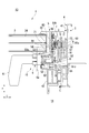
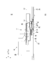
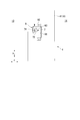
- FIG. 2 is a sectional view taken along line AA in FIG. 1. It is a B direction arrow line view of FIG. It is a C direction arrow directional view of FIG.
- the sash 1 is a composite sash made of aluminum and resin for a vertical extending window.
- the sash 1 is attached to the sash frame 2 fixed to the opening 12 of the building 11 and to the inside of the sash frame 2 so as to be rotatable about a suspension base 3a extending in the vertical direction (direction of arrow D in the figure).
- a sash shoji 3 is attached to the sash frame 2 fixed to the opening 12 of the building 11 and to the inside of the sash frame 2 so as to be rotatable about a suspension base 3a extending in the vertical direction (direction of arrow D in the figure).
- the sash frame 2 is formed in a rectangular shape along the edge of the opening 12, and has an upper frame 21 and a lower frame 22 that extend in the direction of finding (the direction of the arrow E in the figure), and extends in the vertical direction.
- a pair of vertical frames 4 and 23 are defined as the first vertical frame 4, and the sash shoji
- the vertical frame 23 that opposes the third hanging rod 33 will be described below as the second vertical frame 23.
- the sash shoji 3 is arranged on the inner side of the upper heel 31 and the lower heel 32 extending in the direction of finding, the door-end heel 5 and the hanging heel ridge 33 extending in the vertical direction, and these ridges 5, 31 to 33. Glass 34.
- it demonstrates below as a well-known thing except the 1st vertical frame 4 of the sash frame 2, and the door-end fence 5 of the sash shoji 3.
- FIG. 1st vertical frame 4 of the sash frame 2 and the door-end fence 5 of the sash shoji 3.
- the first vertical frame 4 is fixed to the building 11 and has a plate-like shape in which the plate surface faces the finding direction (that is, the plate surface is arranged at an angle with respect to the finding direction). It has a main body 41 and a hiding part 42 supported by the main body 41. Both the main body 41 and the hiding part 42 are members that extend over the entire height of the sash frame 2.
- the main body 41 is made of a metal such as aluminum
- the cover-up portion 42 is made of a resin such as polyvinyl chloride (PVC) having a lower thermal conductivity than the material forming the main body 41.
- PVC polyvinyl chloride
- the door-end fence 5 includes an outdoor-side shape member 51 disposed on the outdoor side 13 side and an indoor-side shape member 52 disposed on the indoor side 14 side of the outdoor-side shape member 51. Both the outdoor-side shape member 51 and the indoor-side shape member 52 are members that extend over the entire height of the sash shoji 3.
- the outdoor shape 51 is made of a metal such as aluminum
- the indoor shape 52 is made of polyvinyl chloride (PVC) or the like having a lower thermal conductivity than the material forming the outdoor shape 51. Resin is used as a material.
- the outdoor shape member 51 includes a first plate portion 53 whose plate surface faces the direction of finding, the size of the prospective direction is substantially the same as the size of the prospective direction of the door rod 5, and the plate surface faces the direction of finding. And a second plate portion 54 having a smaller dimension in the prospective direction than the portion 53.
- that the plate surface faces the finding direction means that the plate surface is arranged so as to have an angle with respect to the finding direction.
- the first plate portion 53 is formed with an engaging portion 53a that can engage with the indoor-side shape member 52 at an intermediate portion in the prospective direction.
- the portion of the first plate portion 53 that is located closer to the interior 14 than the engaging portion 53 a is configured to hold the end surface of the interior-side shaped member 52 that faces the first vertical frame 4.
- the first plate portion 53 is formed with a first long hole 55 extending in the vertical direction.
- the 2nd board part 54 is provided so that it may overlap with the surface facing the 1st vertical frame 4 of the part of the 1st board part 53 located in the outdoor 13 side rather than the engaging part 53a.
- a second long hole 56 and a third long hole 57 extending in the vertical direction are formed in the second plate portion 54 with a space in the vertical direction.
- the first long hole 55, the second long hole 56, and the third long hole 57 are formed so that the lengths in the vertical direction have substantially the same dimensions.
- the first plate portion 53 and the second plate portion 54 extend over the entire height of the sash shoji 3.
- the gremon handle structure 10 is provided on the side of the first vertical frame 4 of the gremon handle 6 provided on the indoor side profile 52 of the door toe 5 and the outdoor shape 51 of the door toe 5.
- a gremon interlocking bar 7, an interlocking portion 8 for interlocking the gremon interlocking bar 7 with the gremon handle 6, and a locking portion 9 provided on the first vertical frame 4 and capable of locking the gremon interlocking bar 7 are provided. .
- the gremon handle 6 is provided at an intermediate portion in the vertical direction of the indoor side shape member 52, protrudes from the indoor side shape member 52 toward the suspension base 3a, and can be gripped by the user. And an inner portion 62 disposed inside the indoor side shape member 52.
- the gremon handle 6 is configured to be rotatable about a shaft 6a that is located at a connecting portion between the grip portion 61 and the inner portion 62 and extends in the prospective direction. When the grip portion 61 rotates downward about the shaft 6a, the inner portion 62 rotates upward, and when the grip portion 61 rotates upward about the shaft 6a, the inner portion 62 is rotated. Is configured to rotate downward.
- the inner portion 62 is connected to the plate 81 of the interlocking portion 8 via a first fixing tool 82 such as a screw inserted through a first long hole 55 formed in the first plate portion 53 of the door toe 5. Yes.
- the first fixing member 82 is configured to be movable in the vertical direction within the first long hole 55.
- the Gremon interlocking bar 7 is provided above the Gremon handle 6 and has a base 71 extending in the direction of finding and a pin (locked portion) provided at the end of the base 71 on the first vertical frame 4 side. 72).
- the end of the base 71 opposite to the side on which the pin 72 is provided is inserted into a second long hole 56 formed in the second plate portion 54 of the door toe 5.
- the base 71 is configured to be movable in the vertical direction within the second long hole 56.
- the pin 72 has a diameter larger than that of the base 71 and is configured not to be able to be inserted into the second long hole 56.
- the side on which the pin 72 is provided protrudes from the second plate portion 54 of the door toe 5 to the first vertical frame 4 side.
- the interlocking unit 8 includes a plate 81 provided on the first vertical frame 4 side of the first plate portion 53 and the second plate portion 54 of the door toe 5, and a space between the first plate portion 53 and the second plate portion 54. And a connecting member 83 that connects the plate 81 and the base 71 of the gremon interlocking bar 7.
- the plate 81 is a substantially rectangular plate material whose plate surface faces the direction of finding, and a stepped portion 81a is formed at an intermediate portion in the prospective direction. In the plate 81, a portion 81b on the outdoor side 13 from the step portion 81a is separated from the first vertical frame 4 than a portion 81c on the indoor side 14 from the step portion 81a.
- the connecting member 83 is connected to the plate 81 of the interlocking portion 8 via a second fixing tool 84 such as a screw inserted into a third long hole 57 formed in the second plate portion 54 of the door toe 5. Yes.
- the second fixture 84 is configured to be movable in the up-down direction within the third elongated hole 57.
- the locking portion 9 is fixed to the main body portion 41 of the first vertical frame 4 at a height corresponding to the gremon interlocking bar 7, and the plate portion 91 and the plate portion 91 are arranged in the first vertical direction. And a fixing portion 92 that is fixed to the frame 4.
- fixed part 92 may be integrally formed, and may be comprised by another member.
- the plate portion 91 has a cutout portion that protrudes downward from the substantially central portion in the prospective direction to the lower side of the outdoor portion 13 from the substantially central portion in the prospective direction while the indoor portion 14 side projects downward from the outdoor 13 side.
- 93 is formed.
- the expected dimension of the notch 93 is set to be larger than the expected dimension of the base 71 of the gremon interlocking bar 7 and smaller than the expected dimension of the pin 72.
- the pin 72 of the gremon interlocking bar 7 is inserted from the lower side between the locking part 9 and the main body part 41 of the first vertical frame 4, and the base 71 of the gremon interlocking bar 7 is inserted into the notch 93 of the locking part 9. When is inserted, the pin 72 is locked, and the movement of the glemon interlocking bar 7 in the direction of finding and in the prospective direction can be restricted.
- the gremon interlocking bar 7 is disposed on the outdoor 13 side in the prospective direction with respect to the gremon handle 6.
- the pin 72 of the gremon interlocking bar 7 is used.
- the arc-shaped trajectory bulging toward the first vertical frame 4 can be reduced. Therefore, the clearance between the pin 72 and the first vertical frame 4 can be reduced. Therefore, the space
- the pin of the gremon interlocking bar 7 extends from the inner part 62.
- Dimensions up to 72 can be reduced. Therefore, the dimension in the direction of finding the door toe 5 can be reduced, and the heat insulating performance of the sash 1 can be further improved.
- the area of the glass 34 can be enlarged by making the dimension of the finding direction of the door-end fence 5 small. Therefore, more light can be obtained from the glass 34 and the viewability can be improved.
- the 1st vertical frame 4 can improve the heat insulation performance of the sash 1 more by having the hiding part 42.
- the plate 81 is formed with a stepped portion 81a at an intermediate portion in the prospective direction.
- the present invention is not limited to the above embodiment, and can be changed as appropriate without departing from the scope of the present invention. It is.
- the sash 1 is a vertically extending window, but may be a side sliding window.
- the pin 72 was provided as a to-be-latched part in the front-end
- the plate 81 has the stepped portion 81a.
- the stepped portion 81a may not be formed.
- a part of the inner part 62 of the gremon handle 6 and a part of the base part 71 of the gremon interlocking bar 7 are provided at a position where they overlap each other in the finding direction. It does not have to be.
- the first vertical frame 4 is provided with the hiding part 42, but the hiding part 42 may not be provided.
Landscapes
- Engineering & Computer Science (AREA)
- Mechanical Engineering (AREA)
- Wing Frames And Configurations (AREA)
Abstract
サッシ枠と、該サッシ枠に吊元を軸として回動可能に支持されるサッシ障子とを備えるサッシに設けられるグレモンハンドル構造は、サッシ障子の戸先框の室内側見込み面に設けられたグレモンハンドルと、戸先框からサッシ枠側へ突出し、サッシ障子とサッシ枠とを係止可能な被係止部が設けられ、グレモンハンドルよりも見込み方向において室外側に設けられたグレモン連動バーと、該グレモン連動バーをグレモンハンドルに連動させる連動部と、を備える。
Description
本発明は、縦辷り出し窓や横辷り出し窓などのサッシ障子が、その吊元を軸として回動可能に取り付けられたサッシに設けられるグレモンハンドル構造およびグレモンハンドル構造が設けられたサッシに関する。
本願は、2014年3月31日に、日本に出願された特願2014-074503号に基づき優先権を主張し、その内容をここに援用する。
本願は、2014年3月31日に、日本に出願された特願2014-074503号に基づき優先権を主張し、その内容をここに援用する。
従来、サッシ障子がその吊元を軸として回動自在に取り付けられた縦辷り出し窓や、横滑り出し窓などには、吊元側と反対側に位置する戸先框にグレモンハンドルが設けられていて、グレモンハンドルと連動するグレモン連動バーが戸先框側の縦枠に係止されることで施錠される構成が知られている(例えば、特許文献1参照)。
また、サッシ障子の戸先框の見付け方向の寸法を小さくし、サッシ障子が開口部を閉鎖している状態において、戸先框がサッシ枠と見込み方向に重なるような隠し框構造が知られている(例えば、特許文献2参照)。このような隠し框構造は、見栄えを良くすることができるとともに、例えばアルミニウムと樹脂の複合サッシなどに適用すると、断熱性能を更に高めることができる。
また、サッシ障子の戸先框の見付け方向の寸法を小さくし、サッシ障子が開口部を閉鎖している状態において、戸先框がサッシ枠と見込み方向に重なるような隠し框構造が知られている(例えば、特許文献2参照)。このような隠し框構造は、見栄えを良くすることができるとともに、例えばアルミニウムと樹脂の複合サッシなどに適用すると、断熱性能を更に高めることができる。
ここで、隠し框構造の縦辷り出し窓のサッシにグレモンハンドルが設けられる場合、戸先框の室内側にグレモンハンドルとグレモン連動バーとが平面視において見付け方向に並んで配列されている。このため、戸先框の見付け方向の寸法は、グレモンハンドルとグレモン連動バーとが、平面視において見付け方向に並んで配列可能な寸法である必要がある。そのため、それぞれの寸法を小さくすることができず、断熱性能を向上させることができない。
また、グレモン連動バーは、サッシ障子が吊元を軸として回動する際には、縦枠と対向する側に位置する先端部のピンが縦枠側に膨む円弧上の軌跡を描くため、縦枠と当たらないようにピンと縦枠との間にクリアランスをとる必要がある。隠し框構造の場合は、戸先框の見込み方向の室内側にグレモンハンドルおよびグレモン連動バーが設けられている。そのため、戸先框の見付け方向の縦枠側にグレモン連動バーが設けられている場合と比べて、サッシ障子が吊元を軸として回動する際に、ピンが縦枠側に大きく膨らむ円弧状の軌跡を描く。従って、ピンと縦枠との間のクリアランスを大きくする必要があり、断熱性能が低くなる。
本発明は、断熱性能を向上させることができるグレモンハンドル構造およびグレモンハンドル構造が設けられたサッシを提供する。
本発明の第1態様は、グレモンハンドル構造であって、サッシ枠と、該サッシ枠に吊元を軸として回動可能に支持されるサッシ障子とを備えるサッシに設けられるグレモンハンドル構造において、前記サッシ障子の戸先框の室内側見込み面に設けられたグレモンハンドルと、前記戸先框から前記サッシ枠側へ突出し、前記サッシ障子と前記サッシ枠とを係止可能な被係止部が設けられ、前記グレモンハンドルよりも見込み方向において室外側に設けられたグレモン連動バーと、該グレモン連動バーを前記グレモンハンドルに連動させる連動部と、を備える。
上記第1態様のグレモンハンドル構造によれば、グレモン連動バーは、グレモンハンドルよりも見込み方向の室外側に配置されている。これにより、グレモン連動バーがグレモンハンドルと見込み方向において重なる位置に配置されている場合と比べて、サッシ障子が吊元を軸として回動した際に、戸先框から突出する被係止部が描くサッシ枠に膨らむ円弧状の軌跡を小さくできる。このため、被係止部とサッシ枠との間のクリアランスを小さくできる。
これにより、戸先框とサッシ枠との間隔を小さくすることができて、サッシの断熱性能を向上させることができる。
これにより、戸先框とサッシ枠との間隔を小さくすることができて、サッシの断熱性能を向上させることができる。
本発明の第2態様は、上記第1態様のグレモンハンドル構造において、前記グレモンハンドルの少なくとも一部と、前記グレモン連動バーの少なくとも一部とは、見付け方向において重なる位置に設けられることが好ましい。
上記第2態様のグレモンハンドル構造によれば、グレモンハンドルとグレモン連動バーとを合わせた見付け方向の寸法を小さくできるため、戸先框の見付け方向の寸法を小さくでき、サッシの断熱性能を向上させることができる。
上記第2態様のグレモンハンドル構造によれば、グレモンハンドルとグレモン連動バーとを合わせた見付け方向の寸法を小さくできるため、戸先框の見付け方向の寸法を小さくでき、サッシの断熱性能を向上させることができる。
本発明の第3態様は、上記第2態様のグレモンハンドル構造において、前記連動部は、板面を含むプレートを有し、該プレートは、前記板面が見付け方向に対して角度を有するように配置され、前記見込み方向における中間部に段部を有し、前記段部よりも室内側の部分に前記グレモンハンドルが連結され、前記段部よりも室外側の部分に前記グレモン連動バーが連結されていて、前記段部よりも室外側の部分は、前記段部よりも室内側の部分と比べて、前記サッシ枠との間の距離が大きいことが好ましい。
上記第3態様のグレモンハンドル構造によれば、グレモンハンドルの少なくとも一部と、グレモン連動バーの少なくとも一部とが見付け方向において重なる位置に設けられる場合にも、グレモンハンドルとグレモン連動バーと連結することができる。従って、グレモンハンドルの操作によって確実にグレモン連動バーを連動させることができる。
上記第3態様のグレモンハンドル構造によれば、グレモンハンドルの少なくとも一部と、グレモン連動バーの少なくとも一部とが見付け方向において重なる位置に設けられる場合にも、グレモンハンドルとグレモン連動バーと連結することができる。従って、グレモンハンドルの操作によって確実にグレモン連動バーを連動させることができる。
本発明の第4態様は、サッシであって、上記第1~第3態様のいずれかに記載のグレモンハンドル構造が設けられている。
本発明の第5態様は、上記第4態様のサッシにおいて、前記サッシ枠は、前記戸先框の室内側において、該戸先框と見込み方向において重なるように配置された框隠し部を有していることが好ましい。
上記第4および第5態様のサッシによれば、サッシの断熱性能をより向上させることができる。
本発明の第5態様は、上記第4態様のサッシにおいて、前記サッシ枠は、前記戸先框の室内側において、該戸先框と見込み方向において重なるように配置された框隠し部を有していることが好ましい。
上記第4および第5態様のサッシによれば、サッシの断熱性能をより向上させることができる。
上記本発明に係る態様によれば、グレモン連動バーは、見込み方向においてグレモンハンドルよりも室外側に配置されている。これにより、グレモン連動バーがグレモンハンドルと見込み方向において重なる位置に配置されている場合と比べて、サッシ障子が吊元を軸として回動した際に、戸先框から突出する被係止部が描くサッシ枠に膨らむ円弧状の軌跡を小さくできる。そのため、被係止部とサッシ枠との間のクリアランスを小さくできる。
これにより、戸先框とサッシ枠との間隔を小さくすることができて、サッシの断熱性能を向上させることができる。
これにより、戸先框とサッシ枠との間隔を小さくすることができて、サッシの断熱性能を向上させることができる。
以下、本発明の実施形態によるグレモンハンドル構造およびグレモンハンドル構造が設けられたサッシについて、図1~図4に基づいて説明する。
図1に示すように、本実施形態によるサッシ1は、縦辷り出し窓のアルミニウムと樹脂との複合のサッシである。サッシ1は、建物11の開口部12に固定されたサッシ枠2と、サッシ枠2の内部に上下方向(図中の矢印Dの方向)に延びる吊元3aを軸として回動可能に取り付けられるサッシ障子3と、を備えている。
図1に示すように、本実施形態によるサッシ1は、縦辷り出し窓のアルミニウムと樹脂との複合のサッシである。サッシ1は、建物11の開口部12に固定されたサッシ枠2と、サッシ枠2の内部に上下方向(図中の矢印Dの方向)に延びる吊元3aを軸として回動可能に取り付けられるサッシ障子3と、を備えている。
サッシ枠2は、開口部12の縁部に沿った矩形状に形成されていて、見付け方向(図中の矢印Eの方向)に延在する上枠21および下枠22と、上下方向に延在する一対の縦枠4,23と、を有している。ここで、一対の縦枠4,23のうち、サッシ障子3が開口部12を閉鎖した状態において、サッシ障子3の戸先框5に対向する縦枠4を第1縦枠4とし、サッシ障子3の吊元框33と対向する縦枠23を第2縦枠23として以下説明する。
サッシ障子3は、見付け方向に延在する上框31および下框32と、上下方向に延在する戸先框5および吊元框33と、これらの框5,31~33の内側に配置されるガラス34と、を有している。
ここで、サッシ枠2の第1縦枠4およびサッシ障子3の戸先框5以外は、公知のものとして以下説明する。
ここで、サッシ枠2の第1縦枠4およびサッシ障子3の戸先框5以外は、公知のものとして以下説明する。
図2に示すように、第1縦枠4は、建物11に固定されて板面が見付け方向を向く(すなわち、板面が見付け方向に対して角度を有するように配置される)板状の本体部41と、本体部41に支持された框隠し部42と、を有している。
本体部41および框隠し部42は、いずれもサッシ枠2の全高さにわたって延在する部材である。本体部41は、アルミニウムなどの金属を材料として形成されていて、框隠し部42は、本体部41を形成する材料よりも熱伝導率の低いポリ塩化ビニル(PVC)などの樹脂を材料として形成されている。
框隠し部42は、サッシ障子3が開口部12を閉鎖している状態において、戸先框5の室内14側で戸先框5と見込み方向(図中の矢印Fの方向)に重なるように配置されている。
本体部41および框隠し部42は、いずれもサッシ枠2の全高さにわたって延在する部材である。本体部41は、アルミニウムなどの金属を材料として形成されていて、框隠し部42は、本体部41を形成する材料よりも熱伝導率の低いポリ塩化ビニル(PVC)などの樹脂を材料として形成されている。
框隠し部42は、サッシ障子3が開口部12を閉鎖している状態において、戸先框5の室内14側で戸先框5と見込み方向(図中の矢印Fの方向)に重なるように配置されている。
戸先框5は、室外13側に配置される室外側形材51と、室外側形材51の室内14側に配置される室内側形材52と、を有している。
室外側形材51および室内側形材52は、いずれもサッシ障子3の全高さにわたって延在する部材である。室外側形材51は、アルミニウムなどの金属を材料として形成されていて、室内側形材52は、室外側形材51を形成する材料よりも熱伝導率の低いポリ塩化ビニル(PVC)などの樹脂を材料として形成されている。
室外側形材51および室内側形材52は、いずれもサッシ障子3の全高さにわたって延在する部材である。室外側形材51は、アルミニウムなどの金属を材料として形成されていて、室内側形材52は、室外側形材51を形成する材料よりも熱伝導率の低いポリ塩化ビニル(PVC)などの樹脂を材料として形成されている。
室外側形材51は、板面が見付け方向を向き、見込み方向の寸法が戸先框5の見込み方向の寸法と略同じ第1板部53と、板面が見付け方向を向き、第1板部53よりも見込み方向の寸法が小さい第2板部54と、を有している。ここで、板面が見付け方向を向くとは、板面が見付け方向に対して角度を有するように配置されることをいう。
第1板部53には、見込み方向の中間部に、室内側形材52と係合可能な係合部53aが形成されていている。係合部53aよりも室内14側に位置する第1板部53の部分は、室内側形材52の第1縦枠4に対向する端面を押さえるように構成されている。第1板部53には、上下方向に延びる第1長孔55が形成されている。
第2板部54は、係合部53aよりも室外13側に位置する第1板部53の部分の第1縦枠4に対向する面と重なるように設けられている。第2板部54には、上下方向に延びる第2長孔56および第3長孔57が上下方向に間隔をあけて形成されている。
なお、第1長孔55、第2長孔56および第3長孔57は、上下方向の長さが略同じ寸法となるように形成されている。
これらの第1板部53および第2板部54は、サッシ障子3の全高さにわたって延在している。
第1板部53には、見込み方向の中間部に、室内側形材52と係合可能な係合部53aが形成されていている。係合部53aよりも室内14側に位置する第1板部53の部分は、室内側形材52の第1縦枠4に対向する端面を押さえるように構成されている。第1板部53には、上下方向に延びる第1長孔55が形成されている。
第2板部54は、係合部53aよりも室外13側に位置する第1板部53の部分の第1縦枠4に対向する面と重なるように設けられている。第2板部54には、上下方向に延びる第2長孔56および第3長孔57が上下方向に間隔をあけて形成されている。
なお、第1長孔55、第2長孔56および第3長孔57は、上下方向の長さが略同じ寸法となるように形成されている。
これらの第1板部53および第2板部54は、サッシ障子3の全高さにわたって延在している。
本実施形態によるグレモンハンドル構造10は、戸先框5の室内側形材52に設けられたグレモンハンドル6と、戸先框5の室外側形材51の第1縦枠4側に設けられたグレモン連動バー7と、グレモンハンドル6にグレモン連動バー7を連動させる連動部8と、第1縦枠4に設けられてグレモン連動バー7を係止可能な係止部9と、を備えている。
グレモンハンドル6は、室内側形材52の上下方向の中間部に設けられていて、室内側形材52から吊元3a側へ突出し使用者が把持可能な把持部61と、把持部61と連結され室内側形材52の内部に配置されるインナー部62と、を有している。
グレモンハンドル6は、把持部61とインナー部62との連結部に位置し見込み方向に延びる軸6aを中心に回動可能に構成されている。そして、軸6aを中心に把持部61が下側に向かって回動するとインナー部62が上側へ向かって回動し、軸6aを中心に把持部61が上側へ向かって回動するとインナー部62が下側へ向かって回動するように構成されている。
グレモンハンドル6は、把持部61とインナー部62との連結部に位置し見込み方向に延びる軸6aを中心に回動可能に構成されている。そして、軸6aを中心に把持部61が下側に向かって回動するとインナー部62が上側へ向かって回動し、軸6aを中心に把持部61が上側へ向かって回動するとインナー部62が下側へ向かって回動するように構成されている。
インナー部62は、戸先框5の第1板部53に形成された第1長孔55に挿通されたビスなどの第1固定具82を介して、連動部8のプレート81と連結されている。この第1固定具82は、第1長孔55内を上下方向に移動可能に構成されている。
グレモン連動バー7は、グレモンハンドル6よりも上部に設けられていて、見付け方向に延在する基部71と、基部71の第1縦枠4側の端部に設けられたピン(被係止部)72と、を有している。
基部71は、ピン72が設けられている側と反対側の端部が、戸先框5の第2板部54に形成された第2長孔56に挿入されている。基部71は、第2長孔56内を上下方向に移動可能に構成されている。
ピン72は、基部71よりも径が大きく形成されていて、第2長孔56に挿通できないように構成されている。
このようなグレモン連動バー7は、ピン72が設けられている側が戸先框5の第2板部54から第1縦枠4側に突出している。
基部71は、ピン72が設けられている側と反対側の端部が、戸先框5の第2板部54に形成された第2長孔56に挿入されている。基部71は、第2長孔56内を上下方向に移動可能に構成されている。
ピン72は、基部71よりも径が大きく形成されていて、第2長孔56に挿通できないように構成されている。
このようなグレモン連動バー7は、ピン72が設けられている側が戸先框5の第2板部54から第1縦枠4側に突出している。
連動部8は、戸先框5の第1板部53および第2板部54の第1縦枠4側に設けられたプレート81と、第1板部53と第2板部54との間に設けられてプレート81とグレモン連動バー7の基部71とを連結する連結材83と、を有している。
プレート81は、板面が見付け方向を向く略矩形状の板材で、見込み方向の中間部に段部81aが形成されている。プレート81は、段部81aより室外13側の部分81bが、段部81aより室内14側の部分81cよりも第1縦枠4と離間している。すなわち、段部81aより室外13側の部分81bの方が、第1縦枠4との間の距離が大きい。
連結材83は、戸先框5の第2板部54に形成された第3長孔57に挿通されたビスなどの第2固定具84を介して、連動部8のプレート81と連結されている。この第2固定具84は、第3長孔57内を上下方向に移動可能に構成されている。
プレート81は、板面が見付け方向を向く略矩形状の板材で、見込み方向の中間部に段部81aが形成されている。プレート81は、段部81aより室外13側の部分81bが、段部81aより室内14側の部分81cよりも第1縦枠4と離間している。すなわち、段部81aより室外13側の部分81bの方が、第1縦枠4との間の距離が大きい。
連結材83は、戸先框5の第2板部54に形成された第3長孔57に挿通されたビスなどの第2固定具84を介して、連動部8のプレート81と連結されている。この第2固定具84は、第3長孔57内を上下方向に移動可能に構成されている。
係止部9は、グレモン連動バー7と対応する高さにおいて第1縦枠4の本体部41に固定されていて、板面が見付け方向を向く板部91と、板部91を第1縦枠4に固定する固定部92と、有している。なお、板部91と固定部92とは一体に形成されていてもよいし、別の部材で構成されていてもよい。
係止部9は、第1縦枠4の本体部41に固定されると、板部91が第1縦枠4の本体部41と見付け方向に離間している。板部91と第1縦枠4の本体部41との間隔は、ピン72の見付け方向の寸法よりも大きくなるように設定されている。
係止部9は、第1縦枠4の本体部41に固定されると、板部91が第1縦枠4の本体部41と見付け方向に離間している。板部91と第1縦枠4の本体部41との間隔は、ピン72の見付け方向の寸法よりも大きくなるように設定されている。
また、板部91は、見込み方向の略中央部よりも室内14側が、室外13側よりも下方に突出しているとともに、見込み方向の略中央部よりも室外13側に下部に開口する切欠き部93が形成されている。切欠き部93の見込み方向の寸法は、グレモン連動バー7の基部71の見込み方向の寸法よりも大きく、ピン72の見込み方向の寸法よりも小さくなるように設定されている。
そして、係止部9は、第1縦枠4の本体部41との間に下側からグレモン連動バー7のピン72が挿入され、係止部9の切り込み93にグレモン連動バー7の基部71が挿入されると、ピン72を係止して、グレモン連動バー7の見付け方向および見込み方向の移動を拘束可能に構成されている。
そして、係止部9は、第1縦枠4の本体部41との間に下側からグレモン連動バー7のピン72が挿入され、係止部9の切り込み93にグレモン連動バー7の基部71が挿入されると、ピン72を係止して、グレモン連動バー7の見付け方向および見込み方向の移動を拘束可能に構成されている。
このようなグレモンハンドル構造10では、サッシ障子3が開口部12を閉鎖した状態で、使用者がグレモンハンドル6の把持部61をその軸6aを中心に下側へ回動させると、インナー部62が上側へ移動し、これに伴いプレート81も上側へ移動する。そして、プレート81が上側へ移動することで連結材83を介してグレモン連動バー7も上側へ移動する。これにより、係止部9の板部91と第1縦枠4との間にピン72が挿入され、ピン72が係止部9に係止されて施錠される。
また、施錠された状態から、使用者が把持部61をその軸6aを中心に上側へ回動させると、インナー部62が下側へ移動し、これに伴いプレート81も下側へ移動する。そして、プレート81が下側へ移動することで連結材83を介してグレモン連動バー7も下側へ移動する。これにより、板部91と第1縦枠4との間からピン72が外れて、解錠される。
また、施錠された状態から、使用者が把持部61をその軸6aを中心に上側へ回動させると、インナー部62が下側へ移動し、これに伴いプレート81も下側へ移動する。そして、プレート81が下側へ移動することで連結材83を介してグレモン連動バー7も下側へ移動する。これにより、板部91と第1縦枠4との間からピン72が外れて、解錠される。
次に、上述したグレモンハンドル構造およびサッシの作用・効果について図面を用いて説明する。
本実施形態によるグレモンハンドル構造10では、グレモン連動バー7は、グレモンハンドル6よりも見込み方向の室外13側に配置されている。これにより、グレモン連動バー7がグレモンハンドル6と見込み方向で重なる位置に配置されている場合と比べて、サッシ障子3が吊元3aを軸として回動した際に、グレモン連動バー7のピン72が描く第1縦枠4側に膨らむ円弧状の軌跡を小さくできる。そのため、ピン72と第1縦枠4との間のクリアランスを小さくできる。
従って、戸先框5と第1縦枠4との間隔を小さくすることができて、サッシ1の断熱性能を向上させることができる。
本実施形態によるグレモンハンドル構造10では、グレモン連動バー7は、グレモンハンドル6よりも見込み方向の室外13側に配置されている。これにより、グレモン連動バー7がグレモンハンドル6と見込み方向で重なる位置に配置されている場合と比べて、サッシ障子3が吊元3aを軸として回動した際に、グレモン連動バー7のピン72が描く第1縦枠4側に膨らむ円弧状の軌跡を小さくできる。そのため、ピン72と第1縦枠4との間のクリアランスを小さくできる。
従って、戸先框5と第1縦枠4との間隔を小さくすることができて、サッシ1の断熱性能を向上させることができる。
また、グレモンハンドル6のインナー部62の一部と、グレモン連動バー7の基部71の一部と、が見付け方向で重なる位置に設けられていることにより、インナー部62からグレモン連動バー7のピン72までの寸法を小さくできる。そのため、戸先框5の見付け方向の寸法を小さくすることができ、サッシ1の断熱性能をより向上させることができる。
また、戸先框5の見付け方向の寸法を小さくできることにより、ガラス34の面積を大きくできる。そのため、ガラス34からより多く採光できるとともに、眺望性をよくすることができる。
また、第1縦枠4は、框隠し部42を有することにより、サッシ1の断熱性能をより向上させることができる。
また、戸先框5の見付け方向の寸法を小さくできることにより、ガラス34の面積を大きくできる。そのため、ガラス34からより多く採光できるとともに、眺望性をよくすることができる。
また、第1縦枠4は、框隠し部42を有することにより、サッシ1の断熱性能をより向上させることができる。
また、プレート81には、見込み方向の中間部に段部81aが形成されている。これにより、グレモンハンドル6のインナー部62の一部と、グレモン連動バー7の基部71の一部と、が見付け方向で重なる位置に設けられている場合にも、グレモンハンドル6のインナー部62とグレモン連動バー7の基部71とを、プレート81および連結材83を介して確実に連結することができる。
以上、本発明によるグレモンハンドル構造およびグレモンハンドル構造が設けられたサッシの実施形態について説明したが、本発明は上記の実施形態に限定されるものではなく、その趣旨を逸脱しない範囲で適宜変更可能である。
例えば、上記の実施形態では、サッシ1は、縦辷り出し窓としているが、横滑り出し窓としてもよい。
また、上記の実施形態では、グレモン連動バー7の先端部に被係止部としてピン72が設けられていて、第1縦枠4に係止部9として切欠き部93が形成された板部91が設けられているが、グレモン連動バー7が第1縦枠4に係止される形態は上記以外の形態としてもよい。
例えば、上記の実施形態では、サッシ1は、縦辷り出し窓としているが、横滑り出し窓としてもよい。
また、上記の実施形態では、グレモン連動バー7の先端部に被係止部としてピン72が設けられていて、第1縦枠4に係止部9として切欠き部93が形成された板部91が設けられているが、グレモン連動バー7が第1縦枠4に係止される形態は上記以外の形態としてもよい。
また、上記の実施形態では、プレート81には、段部81aが形成されているが、段部81aが形成されていなくてもよい。
また、上記の実施形態では、グレモンハンドル6のインナー部62の一部と、グレモン連動バー7の基部71の一部とが、見付け方向で重なる位置に設けられているが、このように設けられていなくてもよい。
また、上記の実施形態では、第1縦枠4には、框隠し部42が設けられているが、框隠し部42が設けられていなくてもよい。
また、上記の実施形態では、グレモンハンドル6のインナー部62の一部と、グレモン連動バー7の基部71の一部とが、見付け方向で重なる位置に設けられているが、このように設けられていなくてもよい。
また、上記の実施形態では、第1縦枠4には、框隠し部42が設けられているが、框隠し部42が設けられていなくてもよい。
1 サッシ
2 サッシ枠
3 サッシ障子
3a 吊元
4 第1縦枠
5 戸先框
6 グレモンハンドル
7 グレモン連動バー
8 連動部
9 係止部
10 グレモンハンドル構造
12 開口部
13 室外
14 室内
42 框隠し部
61 把持部
72 ピン(被係止部)
81 プレート
81a 段部
2 サッシ枠
3 サッシ障子
3a 吊元
4 第1縦枠
5 戸先框
6 グレモンハンドル
7 グレモン連動バー
8 連動部
9 係止部
10 グレモンハンドル構造
12 開口部
13 室外
14 室内
42 框隠し部
61 把持部
72 ピン(被係止部)
81 プレート
81a 段部
Claims (5)
- サッシ枠と、該サッシ枠に吊元を軸として回動可能に支持されるサッシ障子とを備えるサッシに設けられるグレモンハンドル構造において、
前記サッシ障子の戸先框の室内側見込み面に設けられたグレモンハンドルと、
前記戸先框から前記サッシ枠側へ突出し、前記サッシ障子と前記サッシ枠とを係止可能な被係止部が設けられ、前記グレモンハンドルよりも見込み方向において室外側に設けられたグレモン連動バーと、
該グレモン連動バーを前記グレモンハンドルに連動させる連動部と、を備える、
グレモンハンドル構造。 - 前記グレモンハンドルの少なくとも一部と、前記グレモン連動バーの少なくとも一部とは、見付け方向において重なる位置に設けられる、請求項1に記載のグレモンハンドル構造。
- 前記連動部は、板面を含むプレートを有し、
該プレートは、前記板面が見付け方向に対して角度を有するように配置され、前記見込み方向における中間部に段部を有し、前記段部よりも室内側の部分に前記グレモンハンドルが連結され、前記段部よりも室外側の部分に前記グレモン連動バーが連結されていて、前記段部よりも室外側の部分は、前記段部よりも室内側の部分と比べて、前記サッシ枠との間の距離が大きい、請求項2に記載のグレモンハンドル構造。 - 請求項1~3のいずれか一項に記載のグレモンハンドル構造が設けられた、サッシ。
- 前記サッシ枠は、前記戸先框の室内側において、該戸先框と見込み方向において重なるように配置された框隠し部を有している、請求項4に記載のサッシ。
Applications Claiming Priority (2)
| Application Number | Priority Date | Filing Date | Title |
|---|---|---|---|
| JP2014074503A JP6291319B2 (ja) | 2014-03-31 | 2014-03-31 | グレモンハンドル構造およびグレモンハンドル構造が設けられたサッシ |
| JP2014-074503 | 2014-03-31 |
Publications (1)
| Publication Number | Publication Date |
|---|---|
| WO2015151585A1 true WO2015151585A1 (ja) | 2015-10-08 |
Family
ID=54239925
Family Applications (1)
| Application Number | Title | Priority Date | Filing Date |
|---|---|---|---|
| PCT/JP2015/053532 Ceased WO2015151585A1 (ja) | 2014-03-31 | 2015-02-09 | グレモンハンドル構造およびグレモンハンドル構造が設けられたサッシ |
Country Status (2)
| Country | Link |
|---|---|
| JP (1) | JP6291319B2 (ja) |
| WO (1) | WO2015151585A1 (ja) |
Families Citing this family (1)
| Publication number | Priority date | Publication date | Assignee | Title |
|---|---|---|---|---|
| JP6251140B2 (ja) * | 2014-08-19 | 2017-12-20 | 株式会社Lixil | 施錠装置 |
Citations (2)
| Publication number | Priority date | Publication date | Assignee | Title |
|---|---|---|---|---|
| JPS5423096U (ja) * | 1977-07-15 | 1979-02-15 | ||
| JP2001055854A (ja) * | 1999-08-18 | 2001-02-27 | Ykk Architectural Products Inc | 開き窓の錠装置 |
-
2014
- 2014-03-31 JP JP2014074503A patent/JP6291319B2/ja active Active
-
2015
- 2015-02-09 WO PCT/JP2015/053532 patent/WO2015151585A1/ja not_active Ceased
Patent Citations (2)
| Publication number | Priority date | Publication date | Assignee | Title |
|---|---|---|---|---|
| JPS5423096U (ja) * | 1977-07-15 | 1979-02-15 | ||
| JP2001055854A (ja) * | 1999-08-18 | 2001-02-27 | Ykk Architectural Products Inc | 開き窓の錠装置 |
Also Published As
| Publication number | Publication date |
|---|---|
| JP2015196963A (ja) | 2015-11-09 |
| JP6291319B2 (ja) | 2018-03-14 |
Similar Documents
| Publication | Publication Date | Title |
|---|---|---|
| JP5395732B2 (ja) | 窓 | |
| JP2017214745A (ja) | オーバーヘッドドアの扉体 | |
| JP6157847B2 (ja) | 開口部装置 | |
| JP2015194058A (ja) | 引違サッシの構造 | |
| JP6291319B2 (ja) | グレモンハンドル構造およびグレモンハンドル構造が設けられたサッシ | |
| JP6001251B2 (ja) | 開口部装置、防火部材 | |
| JP6763695B2 (ja) | 建具 | |
| JP6245823B2 (ja) | 開口部装置 | |
| JP2008285912A (ja) | カーテンウォールのパネルユニット | |
| JP2017031698A (ja) | 建具 | |
| JP7002984B2 (ja) | 建具 | |
| JP5385645B2 (ja) | 上げ下げ窓 | |
| JP5444067B2 (ja) | ガラスルーバー窓 | |
| JP2017180056A (ja) | 建具 | |
| KR101266844B1 (ko) | 완전 개방이 가능한 이중 연동 도어 구조를 갖는 시스템 창호 | |
| JP6494365B2 (ja) | ドア | |
| JP2009280999A (ja) | 断熱性に優れる開口部装置 | |
| JP2018003393A (ja) | 建具 | |
| JP6325373B2 (ja) | 上げ下げ窓 | |
| JP6433833B2 (ja) | ロック装置及び建具 | |
| JP5986004B2 (ja) | 建具 | |
| JP6595322B2 (ja) | 建具 | |
| JP5328746B2 (ja) | 建具 | |
| JP5564404B2 (ja) | ルーバー窓、及びルーバー窓の施工方法 | |
| JP6780916B2 (ja) | 建具 |
Legal Events
| Date | Code | Title | Description |
|---|---|---|---|
| 121 | Ep: the epo has been informed by wipo that ep was designated in this application |
Ref document number: 15772414 Country of ref document: EP Kind code of ref document: A1 |
|
| NENP | Non-entry into the national phase | ||
| 122 | Ep: pct application non-entry in european phase |
Ref document number: 15772414 Country of ref document: EP Kind code of ref document: A1 |