WO2015147083A1 - コンバイン - Google Patents
コンバイン Download PDFInfo
- Publication number
- WO2015147083A1 WO2015147083A1 PCT/JP2015/059202 JP2015059202W WO2015147083A1 WO 2015147083 A1 WO2015147083 A1 WO 2015147083A1 JP 2015059202 W JP2015059202 W JP 2015059202W WO 2015147083 A1 WO2015147083 A1 WO 2015147083A1
- Authority
- WO
- WIPO (PCT)
- Prior art keywords
- flap
- combine
- chaff sheave
- side frame
- strollac
- Prior art date
- Legal status (The legal status is an assumption and is not a legal conclusion. Google has not performed a legal analysis and makes no representation as to the accuracy of the status listed.)
- Ceased
Links
- 0 CC*1C(C2)[C@]2(CC2)C2C1 Chemical compound CC*1C(C2)[C@]2(CC2)C2C1 0.000 description 2
Images











Classifications
-
- A—HUMAN NECESSITIES
- A01—AGRICULTURE; FORESTRY; ANIMAL HUSBANDRY; HUNTING; TRAPPING; FISHING
- A01F—PROCESSING OF HARVESTED PRODUCE; HAY OR STRAW PRESSES; DEVICES FOR STORING AGRICULTURAL OR HORTICULTURAL PRODUCE
- A01F12/00—Parts or details of threshing apparatus
- A01F12/30—Straw separators, i.e. straw walkers, for separating residual grain from the straw
- A01F12/32—Straw separators, i.e. straw walkers, for separating residual grain from the straw with shaker screens or sieves
-
- A—HUMAN NECESSITIES
- A01—AGRICULTURE; FORESTRY; ANIMAL HUSBANDRY; HUNTING; TRAPPING; FISHING
- A01F—PROCESSING OF HARVESTED PRODUCE; HAY OR STRAW PRESSES; DEVICES FOR STORING AGRICULTURAL OR HORTICULTURAL PRODUCE
- A01F12/00—Parts or details of threshing apparatus
- A01F12/44—Grain cleaners; Grain separators
- A01F12/444—Fanning means
Definitions
- the present invention relates to a combine.
- Chaff sheave sorts the grain by shaking the threshing.
- the selected grain is guided by the first-class cereal board and collected in the first basket provided below the chaff sheave.
- the combine is equipped with the strola back behind the chaff sheave (for example, refer patent document 2).
- the Strollac receives the threshing sent from the chaff sheave and sorts the grains by swinging the threshing.
- the selected grain is guided by the second flow grain board and collected in the second basket provided below the Strollac.
- the combine is provided with a fan that sends wind toward the chaff sheave or stroller (see, for example, Patent Document 3).
- the fan blows away the dust on the chaff sheave or the like and the dust falling from the chaff sheave.
- the fan blows away the dust and the like on the Strollac and the dust that has fallen from the Strollack.
- the object of the present invention is to provide a combine that can change the strength and direction of the wind surrounding the chaff sheave according to the characteristics of the grain. Moreover, it aims at providing the combine which can change the attachment angle of a Strollac so that the moderate wind according to the characteristic of a grain may hit.
- the first aspect of the present invention is: With chaff sheave, A stroll back disposed behind the chaff sheave; In the combine comprising the chaff sheave and the fan that sends wind to the Strollac, An upper flow guide that divides the wind sent out by the fan into two; The air passage formed along the upper flow guide is provided with a flap for adjusting the passage area of the air passage.
- the second aspect of the present invention is the combine according to the first aspect, A side frame that supports the chaff sheave and the stroller;
- the flap is configured such that the passage area of the air passage can be adjusted by overlapping the round hole of the flap with any one of the fastening holes provided in the side frame and fastening the fastening member.
- a third aspect of the present invention is the combine according to the first aspect, A side frame that supports the chaff sheave and the stroller;
- the flap is configured such that the passage area of the air passage can be adjusted by superimposing a long hole of the flap on a fastening hole provided in the side frame and fastening a fastening member.
- a fourth aspect of the present invention is the combine according to the first aspect, A link mechanism for rotating the flap; The flap is configured such that the passage area of the air passage can be adjusted by the movement of the link mechanism.
- the fifth aspect of the present invention is: With chaff sheave, A stroll back disposed behind the chaff sheave; A side frame that supports the chaff sheave and the Strollac, In the combine in which the first bowl is provided below the chaff sheave and the first cereal board is installed from the first bowl toward the Strollack, The Strollac can change the mounting angle with respect to the first cereal board.
- the sixth aspect of the present invention is the combine according to the fifth aspect,
- the Strollac has a structure in which a plurality of rack plates are fixed to one rack beam and a flange is provided at an end of the rack beam.
- the Strollac is capable of changing the mounting angle with respect to the first cereal plate by overlapping the round hole of the flange with any bolt hole provided in the side frame and tightening the bolt. .
- the seventh aspect of the present invention is the combine according to the fifth aspect,
- the Strollac has a structure in which a plurality of rack plates are fixed to one rack beam and a flange is provided at an end of the rack beam.
- the Strollac is configured such that the mounting angle with respect to the first cereal plate can be changed by overlapping the elongated hole of the flange with the bolt hole provided in the side frame and tightening the bolt.
- the eighth aspect of the present invention is the combine according to any one of the fifth to seventh aspects,
- the Strollac can change the mounting angle with respect to the first flow cereal plate within a range that falls below the extension line of the first flow cereal plate.
- the ninth aspect disclosed in the present application is: With chaff sheave, A stroll back disposed behind the chaff sheave; In the combine comprising the chaff sheave and the fan that sends wind to the Strollac, A lower flow guide for branching the wind sent out by the fan into two; The air passage formed along the lower flow guide is provided with a flap for adjusting the passage area of the air passage.
- the tenth aspect disclosed in the present application is the combine according to the ninth aspect, A side frame that supports the chaff sheave and the stroller; A side panel arranged along the side frame, The flap can adjust the passage area of the air passage by overlapping the round hole of the flap on one of the fastening holes provided in the side frame or the side panel and tightening the fastening member. It is.
- the eleventh aspect disclosed in the present application is the combine according to the ninth aspect, A side frame that supports the chaff sheave and the stroller; A side panel arranged along the side frame, The flap is configured such that the passage area of the air passage can be adjusted by overlapping a long hole of the flap on a fastening hole provided in the side frame or the side panel and fastening a fastening member.
- the twelfth aspect disclosed in the present application is the combine according to the ninth aspect, A link mechanism for rotating the flap;
- the flap is configured such that the passage area of the air passage can be adjusted by the movement of the link mechanism.
- the combine includes the upper flow guide that branches the wind sent out by the fan into two. And the flap for adjusting the passage area of this air path is provided in the air path formed along an upper flow guide.
- the combine includes a side frame that supports the chaff sheave and the strollac.
- the flap can adjust the passage area of the air passage by overlapping the round hole of the flap with any one of the fastening holes provided in the side frame and fastening the fastening member.
- the combine includes a side frame that supports the chaff sheave and the stroll rack.
- the flap can adjust the passage area of the air passage by overlapping the elongated hole of the flap on the fastening hole provided in the side frame and fastening the fastening member.
- the combine includes a link mechanism that rotates the flap. And the flap can adjust the passage area of an air path by the movement of a link mechanism.
- strength and direction of the wind which surround a chaff sheave etc. can be changed according to the characteristic of a grain, a grain does not blow off with a sawdust etc. Therefore, the grain sorting accuracy can be improved.
- the Strollac can change the mounting angle with respect to the first cereal board. Therefore, since the attachment angle of a Strollac can be changed so that the moderate wind according to the characteristic of a grain may hit, a grain does not blow off with a sawdust etc. Therefore, the grain sorting accuracy can be improved.
- the Strollac changes the mounting angle with respect to the first cereal plate by overlapping the round hole of the flange with any bolt hole provided in the side frame and tightening the bolt. it can.
- the attachment angle of a Strollac can be selected so that the appropriate wind according to the characteristic of a grain may hit, a grain does not blow off with a sawdust etc. Therefore, the grain sorting accuracy can be improved.
- the Strolac can change the mounting angle with respect to the first cereal plate by overlapping the elongated hole of the flange with the bolt hole provided in the side frame and tightening the bolt.
- the Strollac can change the mounting angle with respect to the first flow cereal plate within a range that falls below the extension line of the first flow cereal plate. Therefore, even if the wind which flows along a 1st flow grain board is strong, a grain does not blow off with sawdust etc. Therefore, the grain sorting accuracy can be improved.
- the combine includes a lower flow guide that divides the wind sent out by the fan into two. And the flap for adjusting the passage area of this air path is provided in the air path formed along a lower flow guide.
- the combine includes a side frame that supports the chaff sheave and the strollac, and a side panel that is disposed along the side frame.
- the flap can adjust the passage area of the air passage by overlapping the round hole of the flap on one of the fastening holes provided in the side frame or the side panel and fastening the fastening member.
- the combine includes a side frame that supports the chaff sheave and the stroller and a side panel that is disposed along the side frame.
- the flap can adjust the passage area of the air passage by overlapping the elongated hole of the flap with the fastening hole provided in the side frame or the side panel and fastening the fastening member.
- the combine includes a link mechanism that rotates the flap. And the flap can adjust the passage area of an air path by the movement of a link mechanism.
- strength and direction of the wind which surround a chaff sheave etc. can be changed according to the characteristic of a grain, a grain does not blow off with a sawdust etc. Therefore, the grain sorting accuracy can be improved.
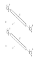
- the figure which shows the structure of a flap The figure which shows the attachment structure of a flap.
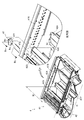
- the figure which shows the attachment structure of a flap The figure which shows each state when the attachment angle of a flap is changed.
- the figure which shows the attachment structure of a flap. The figure which shows each state when the attachment angle of a flap is changed.
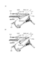
- the figure which shows the link mechanism which rotates a flap. The figure which shows the flow of the wind surrounding Strollac.
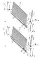
- the figure which shows the structure of a Strollac. The figure which shows the attachment structure of Strollac.
- the figure which shows each state when the attachment angle of a Strollac is changed.
- the figure which shows the attachment structure of Strollac. The figure which shows each state when the attachment angle of a Strollac is changed.
- the figure which shows the sorting apparatus which attached the 2nd air blower. The figure which shows the attachment structure of a 2nd air blower.
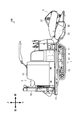
- FIG. 1 shows the left side of the combine 100.
- FIG. 2 shows the right side surface of the combine 100.
- the front-rear direction and the vertical direction of the combine 100 are shown.
- the combine 100 is mainly composed of a traveling device 1, a reaping device 2, a threshing device 3, a sorting device 4, a storage device 5, and a power device 6.
- the traveling device 1 is provided below the chassis frame 10.
- the traveling device 1 includes a transmission 11 and a pair of left and right crawler devices 12 and 12.
- the transmission 11 transmits the power of a diesel engine 61 described later to the crawler devices 12 and 12.
- the crawler devices 12 and 12 cause the combine 100 to travel in the front-rear direction.
- the crawler devices 12 and 12 turn the combine 100 in the left-right direction.
- the cutting device 2 is provided in front of the traveling device 1.
- the cutting device 2 includes a reel 21, a cutter 22, an auger 23, a conveyor 24, and a rotor 25.
- the reel 21 guides the cereal straw in the field to the cutter 22 by rotating.
- the cutter 22 cuts the cereal bowl guided by the reel 21.
- the auger 23 collects the cereals cut by the cutter 22 at a predetermined position.
- the conveyor 24 conveys the cereals collected by the auger 23 to the rotor 25.
- the rotor 25 sends the cereals conveyed by the conveyor 24 to the threshing device 3.
- the threshing device 3 is provided behind the reaping device 2.
- the threshing device 3 includes a handling drum 31 and a receiving net 32.
- the handling drum 31 threshs the cereal by rotating.
- the handling drum 31 conveys the cereal by rotating.
- the receiving net 32 supports the cereals conveyed by the handling cylinder 31 and drops the cereal to the sorting device 4.
- the grain mash after threshing is finely cut by a cutter and discharged.
- the sorting device 4 is provided below the threshing device 3.
- the sorting device 4 includes a swing device 41 and a blower device 42.
- the oscillating device 41 sifts through the cereal and sorts the grain.
- the air blower 42 blows away the dust remaining on the rocking device 41. Note that sawdust and the like are finely cut by a cutter and discharged.
- the storage device 5 is provided on the side of the threshing device 3 and the sorting device 4.
- the storage device 5 includes a Glen tank 51 and a discharge auger 52.
- the Glen tank 51 stores the grains that have been conveyed from the sorting device 4.
- the discharge auger 52 is used when discharging the grains in the grain tank 51.
- the discharge auger 52 is rotated when performing the grain discharging operation, and can discharge the grain to an arbitrary place.
- the power unit 6 is provided in front of the storage unit 5.
- the power unit 6 is composed of a diesel engine 61.
- the diesel engine 61 converts thermal energy obtained by burning fuel into kinetic energy. More specifically, the diesel engine 61 converts thermal energy obtained by burning fuel into power such as the traveling device 1.
- An electric motor that generates power by electricity may also be used.
- threshing will be described as “threshing C”, grain as “grain G”, and sawdust as “sawdust S”.
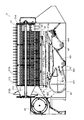
- FIG. 3 shows the threshing device 3 and the sorting device 4.
- FIG. 4 shows the structure of the sorting device 4.
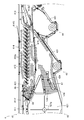
- FIG. 5 shows a situation where the sorting device 4 is sorting the grains G. In the figure, the direction in which the grain G which is the threshing C and the sawdust S, etc. moves is shown. In the figure, the direction of the wind flow by the fan 421 is shown.
- the threshing device 3 includes the handling drum 31 and the receiving net 32.
- the handling drum 31 threshs the cereal by rotating.
- the handling drum 31 conveys the cereal by rotating.
- the receiving net 32 supports the cereals conveyed by the handling cylinder 31 and drops the cereal C to the sorting device 4.
- the handling cylinder 31 mainly includes a center shaft 311, an impeller 312, and a tooth bar 313.
- an impeller 312 is disposed at the front end portion of the center shaft 311, and a plurality of tooth bars 313 are disposed behind the impeller 312 around the center shaft 311.
- the center shaft 311 is a long and linear structure.
- the center shaft 311 supports the impeller 312 and the tooth bar 313.
- the center shaft 311 supports the impeller 312 at the front end portion, and supports the plurality of tooth bars 313 from the center portion to the rear end portion.
- the center shaft 311 has a front end portion and a rear end portion that are rotatably supported by the case 314.
- the impeller 312 is a structure in which a spiral blade 312b is formed.
- the impeller 312 scrapes the cereal that has been fed by the rotor 25. In other words, the impeller 312 rotates to take in the cereals that have been fed by the rotor 25 and send them back.
- the impeller 312 is not limited to the structure including the spiral blade 312b, and may be a structure including a plurality of blades.
- the tooth bar 313 is a structure in which a plurality of handle teeth 313t are attached in parallel at a predetermined interval.
- the tooth bar 313 threshs the cereal meal sent out by the impeller 312. That is, when the tooth bar 313 rotates, the tooth cereal sent out by the impeller 312 is swallowed and the cereal C is dropped.
- the tooth bar 313 is not limited to a structure including a plurality of handle teeth 313t, and may be a structure that supports a spiral blade. Further, instead of forming a cylindrical rotating body by the plurality of tooth bars 313, a structure in which a plurality of handle teeth 313t are provided on one cylindrical member may be used.
- the receiving network 32 is mainly composed of a network body 321.
- the net body 321 is arranged so as to cover the lower side of the rotating body constituted by the plurality of tooth bars 313.
- the net body 321 is a structure in which a plurality of wires 321w are stretched in parallel at a predetermined interval.
- the net body 321 supports the culm that is swallowed by the tooth bar 313.
- the net body 321 drops the cereal C from the gap into the sorting device 4. Note that the left end and the right end of the net 321 are supported by the case 314 in a detachable manner.
- the sorting device 4 includes the swing device 41 and the blower device 42.
- the swinging device 41 sorts the grain G by sifting the cereal cereal C.
- the blower 42 sorts the grain G by blowing away the sawdust S and the like contained in the cereal C.
- the rocking device 41 is mainly composed of a feed pan 411, a chaff sheave 412, a stroller 413, and a separator 414.
- a chaff sheave 412 is disposed behind the feed pan 411
- a stroller 413 is disposed behind the chaff sheave 412.
- a separator 414 is disposed above the chaff sheave 412.
- the feed pan 411 is a wide and flat structure.
- the feed pan 411 receives the threshing C that has fallen from the receiving net 32. Further, the feed pan 411 swings back and forth, and moves the cereal C on the feed pan 411 while moving backward. At this time, the threshing C is spread evenly in the left-right direction by the fins 411f attached obliquely.
- the chaff sheave 412 is a structure in which a plurality of sheave plates 412p are attached in parallel at predetermined intervals.
- the chaff sheave 412 filters the cereal C that has been sent from the feed pan 411. That is, the chaff sheave 412 is swung back and forth, and sifts the cereal crop C sent from the feed pan 411. Thereby, the sawdust etc. S mixed in the cereal C can be lifted and separated from the grain G. In this way, the chaff sheave 412 sorts the grains G from the cereals C (referred to as “fine sorting”).
- the cereal C (only the grain G) is passed through the sieve net 415 and then guided to the first flow grain plate 431 and falls to the top 43. Further, the threshing C remaining on the chaff sheave 412 moves rearward and is sent to the stroller 413.
- the Strollac 413 is a structure in which a plurality of rack plates 413p are attached in parallel at a predetermined interval.
- the Strollac 413 filters the cereal cereal C sent from the chaff sheave 412. That is, the Strollac 413 swings back and forth, and sifts the cereals C sent from the chaff sheave 412. Thereby, relatively large sawdust S and the like mixed in the cereal C can be supported and separated from the grain G. In this way, the Strollac 413 performs sorting (referred to as “fine sorting”) of the grain G from the cereal C.
- the cereal C after the fine selection (the grain G and a small number of small swarf S or the like S) is guided to the second cereal plate 441 and falls to the second bowl 44. Further, the threshing C remaining on the Strollac 413 moves rearward and is discharged to the outside.
- the separator 414 is a structure in which countless holes are provided in a wide flat plate material.
- the separator 414 filters the cereal C that has fallen from the receiving net 32. That is, the separator 414 swings back and forth to screen the cereal C that has fallen from the receiving net 32. Thereby, comparatively large sawdust S etc. mixed in the cereal C can be caught and separated from the remaining cereal C.
- the separator 414 removes relatively large swarf and the like S from the cereal crop C (referred to as “rough sorting”).
- the cereal C after the coarse selection (the grain G and a large number of small sawdusts S) falls directly to the chaff sheave 412. Further, the cereal cereal C remaining on the separator 414 moves rearward and falls to the stroller 413. At this time, the cereal C is further sieved by the sieve line 414S.
- the chaff sheave 412 sifts the cereal C falling from the separator 414 together with the cereal C sent from the feed pan 411.
- the cereal C after the fine sorting passes through the sieve net 415 and is then guided to the first flow grain plate 431 and falls down to the top 43. Further, the threshing C remaining on the chaff sheave 412 moves rearward and is sent to the stroller 413.
- the Strollac 413 sifts the cereal C falling from the separator 414 together with the cereal C sent from the chaff sheave 412.
- the cereal C after the fine sorting (the grain G and a small number of small swarf S or the like S) is guided by the second cereal board 441 and falls to the second bowl 44. Further, the threshing C remaining on the Strollac 413 moves rearward and is discharged to the outside.
- the blower 42 is mainly composed of a fan 421 and a fan case 422.
- a fan 421 is disposed below the feed pan 411, and a fan case 422 is disposed so as to cover the fan 421.
- the fan 421 is a structure in which a plurality of fan plates 421p are attached at predetermined angles.
- the fan 421 sends wind toward the chaff sheave 412 and the stroller 413, and blows off the dust S and the like.
- the fan 421 blows away the sawdust etc. S on the chaff sheave 412 and the sawdust S dropped from the chaff sheave 412 by rotating and sending out the wind.
- the fan 421 rotates to send out the wind, thereby blowing away the waste dust S on the Strollac 413 and the waste S falling from the Strollac 413.
- comparatively small swarf etc. S mixed in the cereal C can be blown away and separated from the grain G.
- the fan 421 selects the grain G from the cereal cereal C.
- the cereal C after sorting (only the grain G) is guided to the first cereal board 431 and falls to the most ridge 43.
- the cereal C after sorting (the grain G and a small number of small swarf S or the like S) is guided by the second cereal board 441 and falls to the second bowl 44.
- the fan case 422 is a structure formed by bending a plate material.
- the fan case 422 covers the fan 421 and guides the wind sent out by the fan 421 in a predetermined direction. More specifically, the fan case 422 branches the wind sent out by the fan 421 into four, and guides them in a predetermined direction.
- FIG. 6 shows the flow of wind surrounding the chaff sheave 412 and the stroller 413.
- the air blower 42 includes an upper flow guide 423.
- the upper flow guide 423 branches the wind sent out upward by the fan 421, directs one side toward the upper surface side of the chaff sheave 412, and directs the other toward the lower surface side of the chaff sheave 412.
- the sawdust S etc. on the chaff sheave 412 and the stroller 413 can be blown off.
- sawdust and the like S that have fallen from the chaff sheave 412 and the stroller 413 can be blown off.
- the sawdust etc. S on the sieve net 415 can be blown off.
- the air blower 42 includes a lower flow guide 424.
- the lower flow guide 424 branches the wind sent out backward by the fan 421, directs one to the chaff sheave 412 through the sieve net 415, and directs the other along the first cereal plate 431 to the stroller 413.
- the sawdust S etc. on the chaff sheave 412 and the stroller 413 can be blown off.
- sawdust and the like S that have fallen from the chaff sheave 412 and the stroller 413 can be blown off.
- the sawdust etc. S on the sieve net 415 can be blown off.
- the first cereal plate 431 is installed from the first basket 43 provided below the chaff sheave 412 toward the stroller 413. For this reason, the wind which flows along the 1st flow grain board 431 is gradually strengthened, and reaches the Strollac 413.
- the combine 100 can adjust the passage area of the air path Up formed along the upper flow guide 423.
- the air path Up refers to a wind path along the upper surface side of the upper flow guide 423.
- the air blowing device 42 includes the upper flow guide 423.
- the upper flow guide 423 branches the wind sent out upward by the fan 421, directs one side toward the upper surface side of the chaff sheave 412, and directs the other toward the lower surface side of the chaff sheave 412. Therefore, the selection accuracy of the grain G by the chaff sheave 412 or the like is affected by the strength or direction of the wind surrounding the chaff sheave 412 or the like. Therefore, by providing the flap 46 for adjusting the passage area of the air passage Up, the strength and direction of the wind surrounding the chaff sheave 412 and the like can be changed.
- the combine 100 includes the upper flow guide 423 that branches the wind sent out by the fan 421 into two.
- a flap 46 for adjusting the passage area of the air path Up is provided in the air path Up formed along the upper flow guide 423.
- FIG. 7 shows the structure of the flap 46.
- (A) is the flap 46 which concerns on 1st embodiment
- (B) is the flap 46 which concerns on 2nd embodiment.
- the flap 46 includes a flap plate 46p and a flange 46f.
- the flap 46 has a structure in which flanges 46f are provided at both ends of the flap plate 46p.
- the flap plate 46p is cut out from a plate material and is formed in a substantially rectangular shape.
- the long side of the flap plate 46p is substantially the same as the lateral dimension of the air path Up (see dimension W in FIG. 8).
- the short side of the flap plate 46p is substantially the same as the vertical dimension of the air path Up (see dimension H in FIG. 8).
- the flange 46f is cut out from the plate material and formed in a substantially trapezoidal shape.
- the flange 46f is provided with a single round hole hx in the upper part thereof. Further, the flange 46f is provided with a single round hole hy at its lower portion (see FIG. 7A). Alternatively, one elongated hole hz is provided in the lower part (see FIG. 7B).
- FIG. 8 shows the attachment structure of the flap 46.
- FIG. 9 shows each state when the attachment angle of the flap 46 is changed. (A) is the state which made the attachment angle small, (B) is the state which made the attachment angle large.
- the upper flow guide 423 is supported by the side frame 416.
- the flap 46 is also supported by the side frame 416.
- the side frame 416 is arranged in parallel to the front-rear direction of the combine 100.
- the side frame 416 is provided with a plurality of bolt holes along the front-rear direction, and an upper flow guide 423 is attached using the bolt holes and bolts.
- the side frame 416 is provided with three fastening holes (hereinafter referred to as “bolt holes”) bx, by1, and by2 at predetermined positions, and the bolt holes bx, by1, and by2 and the bolts Bx and By are provided.
- a flap 46 is attached using it.
- the bolt holes bx, by1, and by2 provided in the side frame 416 will be described.
- the side frame 416 is provided with a bolt hole bx corresponding to the round hole hx of the flange 46f. Therefore, the fastening member (hereinafter referred to as “bolt”) Bx can be tightened by superimposing the round hole hx of the flange 46f on the bolt hole bx provided in the side frame 416. Further, the side frame 416 is provided with two bolt holes by1 and by2 corresponding to the round holes hy of the flange 46f. The two bolt holes by1 and by2 are provided on an arc centered on the bolt hole bx. Therefore, one of the bolt holes by1 and by2 can be selected, and the fastening member (hereinafter referred to as “bolt”) By can be tightened by overlapping the round holes hy of the flange 46f.
- bolt fastening member
- the bolt Bx is overlapped with the bolt hole bx provided in the side frame 416 and the bolt Bx is tightened, and the bolt hole by1 provided in the side frame 416 is overlapped with the round hole hy of the flange 46f.
- the flap 46 is parallel to the feed pan 411 (0 degree with respect to the feed pan 411: see FIG. 9A). At this time, the passage area of the air passage Up is the largest.
- the round hole hx of the flange 46f is overlapped with the bolt hole bx provided in the side frame 416 and the bolt Bx is tightened, and the round hole hy of the flange 46f is overlapped with the bolt hole by2 provided in the side frame 416.
- the flap 46 is substantially perpendicular to the feed pan 411 (approximately 90 degrees with respect to the feed pan 411: see FIG. 9B).
- the passage area of the air passage Up is the smallest. In the present combine 100, the air path Up is closed.
- the flap 46 is tightened by overlapping the round hole hy of the flap 46 (the flange 46f constituting the flap 46) with any of the bolt holes (by1 or by2) provided in the side frame 416.
- the passage area of the air passage Up can be adjusted.
- the installation angle is not limited to this.
- the side frame 416 can be provided with more bolt holes by1, by2,.
- the technical idea of the present invention is that the passage area of the air passage Up can be adjusted by selecting one of the bolt holes by1 and by2 and fixing the flap 46.
- FIG. 10 shows the attachment structure of the flap 46.
- FIG. 11 shows each state when the attachment angle of the flap 46 is changed. (A) is the state which made the attachment angle small, (B) is the state which made the attachment angle large.
- the upper flow guide 423 is supported by the side frame 416.
- the flap 46 is also supported by the side frame 416.
- the side frame 416 is arranged in parallel to the front-rear direction of the combine 100.
- the side frame 416 is provided with a plurality of bolt holes along the front-rear direction, and an upper flow guide 423 is attached using the bolt holes and bolts.
- the side frame 416 is provided with two fastening holes (hereinafter referred to as “bolt holes”) bx / bz at predetermined positions, and flaps using the bolt holes bx / bz and the bolts Bx / Bz. 46 is attached.
- bolt holes bx and bz provided in the side frame 416 will be described.
- the side frame 416 is provided with a bolt hole bx corresponding to the round hole hx of the flange 46f. Therefore, the fastening member (hereinafter referred to as “bolt”) Bx can be tightened by superimposing the round hole hx of the flange 46f on the bolt hole bx provided in the side frame 416. Further, the side frame 416 is provided with a bolt hole bz corresponding to the elongated hole hz of the flange 46f. In addition, the long hole hz is formed in the circular arc shape centering on the round hole hx.
- the fastening member (hereinafter referred to as “bolt”) Bz can be tightened by overlapping the elongated holes hz of the flange 46f at a position where the height with respect to the bolt hole bz is shifted.
- the round hole hx of the flange 46f is overlapped with the bolt hole bx provided in the side frame 416 and the bolt Bx is tightened, and the lower end of the long hole hz of the flange 46f is overlapped with the bolt hole bz provided in the side frame 416.
- the flap 46 is parallel to the feed pan 411 (0 degree with respect to the feed pan 411: see FIG. 11A). At this time, the passage area of the air passage Up is the largest.
- the round hole hx of the flange 46f is overlapped with the bolt hole bx provided in the side frame 416 and the bolt Bx is tightened, and the upper end of the long hole hz of the flange 46f is overlapped with the bolt hole bz provided in the side frame 416.
- the flap 46 is substantially perpendicular to the feed pan 411 (approximately 90 degrees with respect to the feed pan 411: see FIG. 11B).
- the passage area of the air passage Up is the smallest. In the present combine 100, the air path Up is closed.
- the flap 46 is overlapped with the bolt hole bz provided in the side frame 416 by overlapping the elongated hole hz of the flap 46 (the flange 46f constituting the flap 46) and tightening the bolt Bz, thereby
- the passage area can be adjusted.
- this combine 100 although it is a design which can adjust an attachment angle between 0 degree
- a longer elongated hole hz can be provided in the flange 46f to widen it.
- the technical idea of the present invention is that the passage area of the air passage Up can be adjusted by shifting the elongated hole hz and fixing the flap 46.
- the flap 46 may have a structure that rotates according to the operation of the operator. Below, this structure is demonstrated easily.
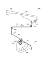
- FIG. 12 shows a link mechanism 46M that rotates the flap 46. As shown in FIG. The arrows in the figure represent the operating directions of the components that make up the link mechanism 46M.
- the link mechanism 46M mainly includes a lever 461, a wire 462, and an arm 463.
- the lever 461 is arranged in the vicinity of the operator. Therefore, the operator can grasp the grip portion 461g of the lever 461 and pull the lever 461 (see arrow A).
- the lever 461 has a shaft portion 461s as a fulcrum, a grip portion 461g as a power point, and a swing portion 461a as an action point.
- the wire 462 is connected to the swing part 461a of the lever 461. Therefore, when the lever 461 is pulled upward by the operator, the wire 462 can be pulled (see arrow B).
- the wire 462 is hung on a plurality of rollers 462r and guided so as to pass a predetermined track.
- the arm 463 is connected to the end of the wire 462. Therefore, when the wire 462 is pulled by the lever 461, the arm 463 can be rotated (see arrow C).
- the arm 463 is fixed to the flap plate 46 p of the flap 46 and is integrated with the flap 46. Therefore, both the arm 463 and the flap 46 rotate (see arrow C). Note that a torsion spring 463t is applied to the flap 46, and a force that resists the direction of rotation by being pulled by the wire 462 is urged.
- the flap 46 rotates according to the operation of the operator. That is, the angle of the flap 46 changes according to the pulling margin of the lever 461. Specifically, the flap 46 rotates from a posture parallel to the feed pan 411 to a posture substantially perpendicular to the feed pan 411 (see FIGS. 9 and 11).
- the flap 46 can adjust the passage area of the air passage Up by the movement of the link mechanism 46M. Therefore, since the intensity
- This combine 100 can adjust the passage area of the air paths Lup and Ldp formed along the lower flow guide 424.
- the air path Lup indicates a path of wind along the upper surface side of the lower flow guide 424.
- the air path Ldp refers to a wind path along the lower surface side of the lower flow guide 424.
- the air blower 42 includes the lower flow guide 424.
- the lower flow guide 424 branches the wind sent out backward by the fan 421, directs one to the chaff sheave 412 through the sieve net 415, and directs the other along the first cereal plate 431 to the stroller 413. Therefore, the selection accuracy of the grain G by the chaff sheave 412 or the like is affected by the strength or direction of the wind surrounding the chaff sheave 412 or the like. Therefore, by providing a flap 47 for adjusting the passage area of the air passages Lup and Ldp, the strength and direction of the wind surrounding the chaff sheave 412 and the like can be changed.
- the combine 100 includes the lower flow guide 424 that branches the wind sent out by the fan 421 into two. Further, a flap 47 for adjusting the passage area of the air paths Lup and Ldp is provided on the air paths Lup and Ldp formed along the lower flow guide 424.
- FIG. 13 shows the structure of the flap 47.
- (A) is the flap 47 which concerns on 1st embodiment
- (B) is the flap 47 which concerns on 2nd embodiment.
- the flap 47 includes a flap plate 47p and a flange 47f.
- the flap 47 has a structure in which flanges 47f are provided at both ends of the flap plate 47p.
- the flap plate 47p is cut out from a plate material and is formed in a substantially rectangular shape.
- the long side of the flap plate 47p is substantially the same as the horizontal dimension of the air paths Lup and Ldp (see dimension W in FIG. 14). Further, the short side of the flap plate 47p is substantially the same as the vertical dimension of the air path Ldp (see dimension H in FIG. 14).
- the flange 47f is cut out from the plate material and formed in a substantially trapezoidal shape.
- the flange 47f is provided with one round hole hx in the upper part thereof. Further, the flange 47f is provided with one round hole hy at the lower portion thereof (see FIG. 13A). Alternatively, one elongated hole hz is provided in the lower part thereof (see FIG. 13B).
- FIG. 14 shows the attachment structure of the flap 47.
- FIG. 15 shows each state when the attachment angle of the flap 47 is changed.
- (A) is a state in which the mounting angle is a predetermined positive angle
- (B) is a state in which the mounting angle is a predetermined negative angle.
- the lower flow guide 424 is supported by the side panel 417.
- the flap 47 is also supported by the side panel 417.
- the side panel 417 is disposed along the side frame 416 and the fan case 422.
- the side panel 417 is arranged in parallel to the front-rear direction of the combine 100.
- the side panel 417 is provided with a plurality of bolt holes along the front-rear direction, and a lower flow guide 424 is attached using the bolt holes and bolts.
- the side panel 417 is provided with three fastening holes (hereinafter referred to as “bolt holes”) bx, by1, and by2 at predetermined positions, and the bolt holes bx, by1, and by2 and the bolts Bx and By are provided.
- the flap 47 is attached using it.
- the bolt holes bx, by1, and by2 provided in the side panel 417 will be described.
- the side panel 417 is provided with a bolt hole bx corresponding to the round hole hx of the flange 47f. Therefore, the fastening member (hereinafter referred to as “bolt”) Bx can be tightened by superimposing the round hole hx of the flange 47f on the bolt hole bx provided in the side panel 417. Further, the side panel 417 is provided with two bolt holes by1 and by2 corresponding to the round holes hy of the flange 47f. The two bolt holes by1 and by2 are provided on an arc centered on the bolt hole bx. Therefore, one of the bolt holes by1 and by2 can be selected, and the fastening member (hereinafter referred to as “bolt”) By can be tightened by overlapping the round holes hy of the flange 47f.
- bolt fastening member
- the bolt Bx is overlapped with the bolt hole bx provided in the side panel 417 and the bolt Bx is tightened, and the bolt hole by1 provided in the side panel 417 is overlapped with the round hole hy of the flange 47f.
- the flap 47 is at an elevation angle with respect to the imaginary line L along the front plate portion of the lower flow guide 424 (predetermined positive with respect to the imaginary line L along the front plate portion of the lower flow guide 424). It becomes an angle: (refer (A) of FIG. 15).
- the passage area of the air passage Lup is the smallest.
- the passage area of the air passage Ldp is the largest. That is, in the present combine 100, the air path Lup is most closed and the air path Ldp is most open.
- the round hole hx of the flange 47f is overlapped with the bolt hole bx provided in the side panel 417 and the bolt Bx is tightened, and the round hole hy of the flange 47f is overlapped with the bolt hole by2 provided in the side panel 417.
- the flap 47 becomes a depression angle with respect to the imaginary line L along the front plate portion of the lower flow guide 424 (a predetermined negative with respect to the imaginary line L along the front plate portion of the lower flow guide 424). It becomes an angle: (see (B) of FIG. 15).
- the passage area of the air passage Lup is the largest. In other words, the passage area of the air passage Ldp is the smallest. That is, in the present combine 100, the air path Lup is most opened and the air path Ldp is most closed.
- the flap 47 is formed by superimposing the round hole hy of the flap 47 (the flange 47f constituting the flap 47) on one of the bolt holes (by1 or by2) provided in the side frame 416 or the side panel 417.
- the passage areas of the air paths Lup and Ldp can be adjusted.
- etc. Can be changed according to the characteristic of the grain G, the grain G does not blow off with the sawdust etc.S. Therefore, it becomes possible to improve the selection accuracy of the grain G.
- the side panel 417 may be provided with more bolt holes by1, by2,.
- the technical idea of the present invention is that the passage area of the air passages Lup and Ldp can be adjusted by selecting any one of the bolt holes by1 and by2 and fixing the flap 47.
- FIG. 16 shows the attachment structure of the flap 47.
- FIG. 17 shows each state when the attachment angle of the flap 47 is changed.
- (A) is a state in which the mounting angle is a predetermined positive angle
- (B) is a state in which the mounting angle is a predetermined negative angle.
- the lower flow guide 424 is supported by the side panel 417.
- the flap 47 is also supported by the side panel 417.
- the side panel 417 is disposed along the side frame 416 and the fan case 422.
- the side panel 417 is arranged in parallel to the front-rear direction of the combine 100.
- the side panel 417 is provided with a plurality of bolt holes along the front-rear direction, and a lower flow guide 424 is attached using the bolt holes and bolts.
- the side panel 417 is provided with two fastening holes (hereinafter referred to as “bolt holes”) bx / bz at predetermined positions, and flaps using the bolt holes bx / bz and the bolts Bx / Bz. 47 is attached.
- bolt holes bx and bz provided in the side panel 417 will be described.
- the side panel 417 is provided with a bolt hole bx corresponding to the round hole hx of the flange 47f. Therefore, the fastening member (hereinafter referred to as “bolt”) Bx can be tightened by superimposing the round hole hx of the flange 47f on the bolt hole bx provided in the side panel 417. Further, the side panel 417 is provided with a bolt hole bz corresponding to the elongated hole hz of the flange 47f. In addition, the long hole hz is formed in the circular arc shape centering on the round hole hx. Therefore, the fastening member (hereinafter referred to as “bolt”) Bz can be tightened by overlapping the elongated holes hz of the flange 47f at a position where the height of the bolt hole bz is shifted.
- the round hole hx of the flange 47f is overlapped with the bolt hole bx provided in the side panel 417 and the bolt Bx is tightened, and the lower end of the long hole hz of the flange 47f is overlapped with the bolt hole bz provided in the side panel 417.
- the flap 47 is at an elevation angle with respect to the imaginary line L along the front plate portion of the lower flow guide 424 (predetermined with respect to the imaginary line L along the front plate portion of the lower flow guide 424). A positive angle is obtained (see FIG. 17A).
- the passage area of the air passage Lup is the smallest.
- the passage area of the air passage Ldp is the largest. That is, in the present combine 100, the air path Lup is most closed and the air path Ldp is most open.
- the round hole hx of the flange 47f is overlapped with the bolt hole bx provided in the side panel 417 and the bolt Bx is tightened, and the upper end of the long hole hz of the flange 47f is overlapped with the bolt hole bz provided in the side panel 417.
- the flap 47 becomes a depression angle with respect to the imaginary line L along the front plate portion of the lower flow guide 424 (predetermined with respect to the imaginary line L along the front plate portion of the lower flow guide 424). A negative angle is obtained (see FIG. 17B).
- the passage area of the air passage Lup is the largest. In other words, the passage area of the air passage Ldp is the smallest. That is, in the present combine 100, the air path Lup is most opened and the air path Ldp is most closed.
- the flap 47 is formed by overlapping the elongated hole hz of the flap 47 (the flange 47f constituting the flap 47) on the bolt hole bz provided in the side frame 416 or the side panel 417 and tightening the bolt Bz.
- the passage area of the air paths Lup and Ldp can be adjusted. Thereby, since the intensity
- this combine 100 although it is the design which can adjust an attachment angle between a predetermined
- a longer elongated hole hz can be provided in the flange 47f to widen the range.
- the technical idea of the present invention is that the passage area of the air passages Lup and Ldp can be adjusted by shifting the elongated hole hz and fixing the flap 47.
- the flap 47 may have a structure that rotates according to the operation of the operator. Below, this structure is demonstrated easily.
- FIG. 18 shows a link mechanism 47M that rotates the flap 47. As shown in FIG. The arrows in the figure represent the operating directions of the components that make up the link mechanism 47M.
- the link mechanism 47M mainly includes a lever 471, a wire 472, and an arm 473.
- the lever 471 is disposed in the vicinity of the operator. Therefore, the operator can grasp the grip portion 471g of the lever 471 and pull the lever 471 (see arrow A).
- the lever 471 has a shaft portion 471 s as a fulcrum, a grip portion 471 g as a power point, and a swing portion 471 a as an action point.
- the wire 472 is connected to the swing part 471a of the lever 471. Therefore, when the lever 471 is pulled upward by the operator, the wire 472 can be pulled (see arrow B).
- the wire 472 is hung on a plurality of rollers 472r and guided so as to pass a predetermined track.
- the arm 473 is connected to the end of the wire 472. Therefore, when the wire 472 is pulled by the lever 471, the arm 473 can be rotated (see arrow C).
- the arm 473 is fixed to the flap plate 47 p of the flap 47 and is integrated with the flap 47. Therefore, the arm 473 and the flap 47 rotate together (see arrow C). Note that a torsion spring 473t is applied to the flap 47, and a force against the direction of rotation by being pulled by the wire 472 is urged.
- the flap 47 is rotated by such a link mechanism 47M according to the operation of the operator. That is, the angle of the flap 47 changes according to the pulling margin of the lever 471. More specifically, the flap 47 has a predetermined positive angle with respect to the virtual line L along the front plate portion of the lower flow guide 424 and the virtual line L along the front plate portion of the lower flow guide 424. To a posture having a predetermined negative angle (see FIGS. 15 and 17).
- the flap 47 can adjust the passage area of the air passage Lup / Ldp by the movement of the link mechanism 47M. Therefore, since the intensity
- FIG. 19 shows the flow of wind surrounding the Strollac 413.
- the wind which flowed along the 1st flow grain board 431 is represented.
- the Strollac 413 of the combine 100 can change the attachment angle ⁇ with respect to the first cereal board 431.
- the Strollac 413 can change the attachment angle ⁇ with respect to the first cereal plate 431.
- the attachment angle (alpha) of the Strollac 413 can be changed so that the moderate wind according to the characteristic of the grain G may hit, the grain G does not blow off with the sawdust etc.S. Therefore, it becomes possible to improve the selection accuracy of the grain G.
- FIG. 20 shows the structure of the stroller 413.
- (A) is the Strollac 413 according to the first embodiment
- (B) is the Strollac 413 according to the second embodiment.
- the Strollac 413 includes a rack plate 413p, a rack beam 413b, and a flange 413f.
- the Strollac 413 has a structure in which a plurality of rack plates 413p are fixed to one rack beam 413b and a flange 413f is provided at an end of the rack beam 413b.
- the rack plate 413p is parallel to each other by bending both wing portions 413w and 413w of a symmetrical plate material backward.
- Each wing portion 413w has a wave shape at its upper end. This is to send the sawdust S and the like S backward using the swing motion.
- blade part 413w connects is provided with the two round holes h up and down.
- the rack beam 413b is welded so that the flat portion 413s of the plate material faces rearward and downward.
- a plurality of rows of two rivet bolts B are attached to the flat portion 413s. Therefore, a plurality of rack plates 413p can be fixed to the plane portion 413s with the nuts N.
- the Strollac 413 has a total of 14 rack plates 413p.
- the flange 413f is formed by cutting out a substantially trapezoidal shape from a plate material. Further, the flange 413f is provided with one round hole hx in the upper part thereof. Further, the flange 413f is provided with a single round hole hy in the lower portion thereof (see FIG. 20A). Alternatively, one long hole hz is provided in the lower part (see FIG. 20B).
- FIG. 21 shows a mounting structure of the stroller 413.
- FIG. 22 shows each state when the attachment angle ⁇ of the Strollac 413 is changed.
- (A) is a state in which the mounting angle ⁇ is increased
- (B) is a state in which the mounting angle ⁇ is decreased.
- the feed pan 411 and the chaff sheave 412 are supported by the side frame 416.
- the Strollac 413 is also supported by the side frame 416.
- the side frame 416 is arranged in parallel to the front-rear direction of the combine 100.
- the side frame 416 is provided with a plurality of bolt holes along the front-rear direction, and the feed pan 411, the chaff sheave 412 and the like are fixed using the bolt holes.
- the side frame 416 is provided with three bolt holes bx, by1, and by2 at predetermined positions, and the stroller 413 is fixed using the bolt holes bx, by1, and by2.
- the bolt holes bx, by1, and by2 provided in the side frame 416 will be described.
- the side frame 416 is provided with a bolt hole bx corresponding to the round hole hx of the flange 413f. Therefore, the bolt Bx can be tightened by superimposing the round hole hx of the flange 413f on the bolt hole bx provided in the side frame 416. Further, the side frame 416 is provided with two bolt holes by1 and by2 corresponding to the round holes hy of the flange 413f. The two bolt holes by1 and by2 are provided on an arc centered on the bolt hole bx. Therefore, one of the bolt holes by1 and by2 can be selected, and the bolt By can be tightened by overlapping the round holes hy of the flange 413f.
- the bolt hole bx provided in the side frame 416 is overlapped with the round hole hx of the flange 413f and the bolt Bx is tightened, and the bolt hole by1 provided in the side frame 416 is overlapped with the round hole hy of the flange 413f.
- the Strollac 413 has a predetermined mounting angle ⁇ 1 (see FIG. 22A).
- the attachment angle ⁇ 1 is an angle formed with respect to the first cereal board 431, and is the same value as that of a conventional combine.
- the Strollac 413 has a predetermined mounting angle ⁇ 2 (see FIG. 22B).
- the attachment angle ⁇ 2 is an angle formed with respect to the first cereal board 431, and is smaller than a conventional combine.
- the Strollac 413 is attached to any bolt hole (by1 or by2) provided in the side frame 416 and overlaps the round hole hy of the flange 413f and tightens the bolt By to thereby tighten the bolt By.
- the mounting angle ⁇ can be changed.
- attachment angle (alpha) 1 or attachment angle (alpha) 2 it is not limited to this.
- the side frame 416 can be provided with more bolt holes by1, by2,.
- the attachment angle ⁇ 1 is the same value as that of the conventional combine and the attachment angle ⁇ 2 is smaller than that of the conventional combine.
- the present invention is not limited to this.
- the technical idea of the present invention is that the mounting angle ⁇ of the stroller 413 is changed by selecting one of the bolt holes by1 and by2 and fixing the stroller 413.
- FIG. 23 shows a mounting structure of the stroller 413.
- FIG. 24 shows each state when the attachment angle ⁇ of the stroller 413 is changed.
- (A) is a state in which the mounting angle ⁇ is increased
- (B) is a state in which the mounting angle ⁇ is decreased.
- the feed pan 411 and the chaff sheave 412 are supported by the side frame 416.
- the Strollac 413 is also supported by the side frame 416.
- the side frame 416 is arranged in parallel to the front-rear direction of the combine 100.
- the side frame 416 is provided with a plurality of bolt holes along the front-rear direction, and the feed pan 411, the chaff sheave 412 and the like are fixed using the bolt holes.
- the side frame 416 is provided with two bolt holes bx / bz at predetermined positions, and the Strollac 413 is fixed by using the bolt holes bx / bz.
- the bolt holes bx and bz provided in the side frame 416 will be described.
- the side frame 416 is provided with a bolt hole bx corresponding to the round hole hx of the flange 413f. Therefore, the bolt Bx can be tightened by superimposing the round hole hx of the flange 413f on the bolt hole bx provided in the side frame 416. Further, the side frame 416 is provided with a bolt hole bz corresponding to the elongated hole hz of the flange 413f. In addition, the long hole hz is formed in the circular arc shape centering on the round hole hx. Therefore, the bolt Bz can be tightened by overlapping the elongated holes hz of the flange 413f at a position where the height of the bolt hole bz is shifted.
- the round hole hx of the flange 413f is overlapped with the bolt hole bx provided in the side frame 416 and the bolt Bx is tightened, and the lower end of the long hole hz of the flange 413f is overlapped with the bolt hole bz provided in the side frame 416.
- the Strollac 413 has a predetermined mounting angle ⁇ 1 (see FIG. 24A).
- the attachment angle ⁇ 1 is an angle formed with respect to the first cereal board 431, and is the same value as that of a conventional combine.
- the round hole hx of the flange 413f is overlapped with the bolt hole bx provided in the side frame 416 and the bolt Bx is tightened, and the upper end of the long hole hz of the flange 413f is overlapped with the bolt hole bz provided in the side frame 416.
- the Strollac 413 has a predetermined mounting angle ⁇ 2 (see FIG. 24B).
- the attachment angle ⁇ 2 is an angle formed with respect to the first cereal board 431, and is smaller than a conventional combine.
- the Strollac 413 can change the mounting angle ⁇ with respect to the first cereal plate 431 by superimposing the long hole hz of the flange 413f on the bolt hole bz provided in the side frame 416 and tightening the bolt Bz.
- the attachment angle (alpha) of the Strollac 413 can be adjusted so that the moderate wind according to the characteristic of the grain G may hit, the grain G does not blow away with Swarf etc. S. Therefore, it becomes possible to improve the selection accuracy of the grain G.
- this combine 100 although it is the design which can be adjusted between the attachment angle (alpha) 1 and the attachment angle (alpha) 2, it is not limited to this.
- a longer elongated hole hz can be provided in the flange 413f to widen it.
- the attachment angle ⁇ 1 is the same value as that of the conventional combine and the attachment angle ⁇ 2 is smaller than that of the conventional combine.
- the present invention is not limited to this.
- the technical idea of the present invention is that the mounting angle ⁇ of the stroller 413 is changed by shifting the elongated hole hz and fixing the stroller 413.
- the Strollac 413 of the combine 100 can change the attachment angle ⁇ with respect to the first cereal board 431.
- the Strollac 413 can change the attachment angle ⁇ with respect to the first flow cereal plate 431 within a range that falls below the extension line L of the first flow cereal plate 431 (FIG. 22B and FIG. 24 (B)).
- the Strollac 413 can change the attachment angle ⁇ with respect to the first flow cereal plate 431 so as to be within a range that falls below the extension line L of the first flow cereal plate 431. Therefore, even if the wind which flows along the 1st flow grain board 431 is strong, the grain G does not blow off with S etc. Therefore, it becomes possible to improve the selection accuracy of the grain G.
- This sorter 4 can attach the 2nd air blower 45 between the first fence 43 and the second fence 44.
- the air blower 42 is demonstrated as "the 1st air blower 42".
- FIG. 25 shows the sorting device 4 to which the second blower 45 is attached.
- FIG. 26 shows the mounting structure of the second blower 45.
- This sorter 4 is common to other components even if the second blower 45 has different specifications. This is because the air vent 45h is provided in the case 442 for the specification with the second air blower 45 attached, and the air vent 45h is closed with the plate 443 in the specification without the second air blower 45 attached. by.
- the ventilation holes 45 h are provided in the case 442, and the ventilation holes 45 h can be closed with the plate 443. Thereby, even if it is the specification from which the presence or absence of the 2nd air blower 45 differs, another component is common. Therefore, cost can be reduced.
- the present invention can be used for combine technology.
Landscapes
- Life Sciences & Earth Sciences (AREA)
- Environmental Sciences (AREA)
- Threshing Machine Elements (AREA)
Abstract
チャフシーブ412と、前記チャフシーブ412の後方に配置されるストローラック413と、前記チャフシーブ412及び前記ストローラック413に風を送るファン421と、を備えたコンバイン100において、前記ファン421が送り出した風を二つに分岐するアッパフローガイド423を具備し、前記アッパフローガイド423に沿って形成される風路Upに該風路Upの通路面積を調節するためのフラップ46を設けた。
Description
本発明は、コンバインに関する。
コンバインは、チャフシーブを備えている(例えば特許文献1参照)。チャフシーブは、脱穀物を揺動することによって穀粒を選別する。選別された穀粒は、第一流穀板によって案内され、チャフシーブの下方に設けられた一番樋に集められる。
また、コンバインは、チャフシーブの後方にストローラックを備えている(例えば特許文献2参照)。ストローラックは、チャフシーブから送られてきた脱穀物を受け止め、該脱穀物を揺動することによって穀粒を選別する。選別された穀粒は、第二流穀板によって案内され、ストローラックの下方に設けられた二番樋に集められる。
更に、コンバインは、チャフシーブやストローラックに向けて風を送るファンを備えている(例えば特許文献3参照)。ファンは、チャフシーブ上の藁屑等や該チャフシーブから落下してきた藁屑等を吹き飛ばす。また、ファンは、ストローラック上の藁屑等や該ストローラックから落下してきた藁屑等を吹き飛ばす。
ところで、穀粒は、同じ品種であったとしても地域によって大きさや重さが異なる。そのため、穀粒の特徴に応じてチャフシーブ等を取り巻く風の強さや方向を変えなければ、脱穀物を舞い上げてしまう場合があった。つまり、藁屑等と一緒に穀粒を吹き飛ばしてしまう場合があったのである。そこで、穀粒の特徴に応じてチャフシーブ等を取り巻く風の強さや方向を変えられるとしたコンバインが求められていた。加えて、ファンによる風が第一流穀板に沿ってストローラックへ向かうと、該ストローラック上の脱穀物を吹き飛ばしてしまう場合もあった。つまり、ファンによる風が藁屑等と一緒に穀粒をも吹き飛ばしてしまう場合があったのである。そこで、穀粒の特徴に応じた適度な風が当たるよう、ストローラックの取付角度を変更できるとしたコンバインが求められていた。
本発明は、穀粒の特徴に応じてチャフシーブ等を取り巻く風の強さや方向を変えられるとしたコンバインを提供することを目的としている。また、穀粒の特徴に応じた適度な風が当たるよう、ストローラックの取付角度を変更できるとしたコンバインを提供することを目的としている。
本発明の第一の態様は、
チャフシーブと、
前記チャフシーブの後方に配置されるストローラックと、
前記チャフシーブ及び前記ストローラックに風を送るファンと、を備えたコンバインにおいて、
前記ファンが送り出した風を二つに分岐するアッパフローガイドを具備し、
前記アッパフローガイドに沿って形成される風路に該風路の通路面積を調節するためのフラップを設けた、ものである。
チャフシーブと、
前記チャフシーブの後方に配置されるストローラックと、
前記チャフシーブ及び前記ストローラックに風を送るファンと、を備えたコンバインにおいて、
前記ファンが送り出した風を二つに分岐するアッパフローガイドを具備し、
前記アッパフローガイドに沿って形成される風路に該風路の通路面積を調節するためのフラップを設けた、ものである。
本発明の第二の態様は、第一の態様に係るコンバインにおいて、
前記チャフシーブ及び前記ストローラックを支持するサイドフレームを具備し、
前記フラップは、前記サイドフレームに設けられたいずれかの締結穴に該フラップの丸穴を重ね合わせて締結部材を締め付けることにより、前記風路の通路面積を調節できる、としたものである。
前記チャフシーブ及び前記ストローラックを支持するサイドフレームを具備し、
前記フラップは、前記サイドフレームに設けられたいずれかの締結穴に該フラップの丸穴を重ね合わせて締結部材を締め付けることにより、前記風路の通路面積を調節できる、としたものである。
本発明の第三の態様は、第一の態様に係るコンバインにおいて、
前記チャフシーブ及び前記ストローラックを支持するサイドフレームを具備し、
前記フラップは、前記サイドフレームに設けられた締結穴に該フラップの長穴を重ね合わせて締結部材を締め付けることにより、前記風路の通路面積を調節できる、としたものである。
前記チャフシーブ及び前記ストローラックを支持するサイドフレームを具備し、
前記フラップは、前記サイドフレームに設けられた締結穴に該フラップの長穴を重ね合わせて締結部材を締め付けることにより、前記風路の通路面積を調節できる、としたものである。
本発明の第四の態様は、第一の態様に係るコンバインにおいて、
前記フラップを回動させるリンク機構を具備し、
前記フラップは、前記リンク機構の可動により、前記風路の通路面積を調節できる、としたものである。
前記フラップを回動させるリンク機構を具備し、
前記フラップは、前記リンク機構の可動により、前記風路の通路面積を調節できる、としたものである。
本発明の第五の態様は、
チャフシーブと、
前記チャフシーブの後方に配置されるストローラックと、
前記チャフシーブ及び前記ストローラックを支持するサイドフレームと、を備え、
前記チャフシーブの下方に一番樋が設けられるとともに該一番樋から前記ストローラックに向けて第一流穀板を設置したコンバインにおいて、
前記ストローラックは、前記第一流穀板に対する取付角度を変更できる、としたものである。
チャフシーブと、
前記チャフシーブの後方に配置されるストローラックと、
前記チャフシーブ及び前記ストローラックを支持するサイドフレームと、を備え、
前記チャフシーブの下方に一番樋が設けられるとともに該一番樋から前記ストローラックに向けて第一流穀板を設置したコンバインにおいて、
前記ストローラックは、前記第一流穀板に対する取付角度を変更できる、としたものである。
本発明の第六の態様は、第五の態様に係るコンバインにおいて、
前記ストローラックは、複数のラックプレートが一のラックビームに固定されるとともに該ラックビームの端部にフランジを設けた構造とされ、
前記ストローラックは、前記サイドフレームに設けられたいずれかのボルト穴に前記フランジの丸穴を重ね合わせてボルトを締め付けることにより、前記第一流穀板に対する取付角度を変更できる、としたものである。
前記ストローラックは、複数のラックプレートが一のラックビームに固定されるとともに該ラックビームの端部にフランジを設けた構造とされ、
前記ストローラックは、前記サイドフレームに設けられたいずれかのボルト穴に前記フランジの丸穴を重ね合わせてボルトを締め付けることにより、前記第一流穀板に対する取付角度を変更できる、としたものである。
本発明の第七の態様は、第五の態様に係るコンバインにおいて、
前記ストローラックは、複数のラックプレートが一のラックビームに固定されるとともに該ラックビームの端部にフランジを設けた構造とされ、
前記ストローラックは、前記サイドフレームに設けられたボルト穴に前記フランジの長穴を重ね合わせてボルトを締め付けることにより、前記第一流穀板に対する取付角度を変更できる、としたものである。
前記ストローラックは、複数のラックプレートが一のラックビームに固定されるとともに該ラックビームの端部にフランジを設けた構造とされ、
前記ストローラックは、前記サイドフレームに設けられたボルト穴に前記フランジの長穴を重ね合わせてボルトを締め付けることにより、前記第一流穀板に対する取付角度を変更できる、としたものである。
本発明の第八の態様は、第五から第七のいずれかの態様に係るコンバインにおいて、
前記ストローラックは、前記第一流穀板の延長線よりも下方に収まる範囲内へ、前記第一流穀板に対する取付角度を変更できる、としたものである。
前記ストローラックは、前記第一流穀板の延長線よりも下方に収まる範囲内へ、前記第一流穀板に対する取付角度を変更できる、としたものである。
更に、本願では、以下の発明を開示する。
本願に開示する第九の態様は、
チャフシーブと、
前記チャフシーブの後方に配置されるストローラックと、
前記チャフシーブ及び前記ストローラックに風を送るファンと、を備えたコンバインにおいて、
前記ファンが送り出した風を二つに分岐させるロワフローガイドを具備し、
前記ロワフローガイドに沿って形成される風路に該風路の通路面積を調節するためのフラップを設けた、ものである。
チャフシーブと、
前記チャフシーブの後方に配置されるストローラックと、
前記チャフシーブ及び前記ストローラックに風を送るファンと、を備えたコンバインにおいて、
前記ファンが送り出した風を二つに分岐させるロワフローガイドを具備し、
前記ロワフローガイドに沿って形成される風路に該風路の通路面積を調節するためのフラップを設けた、ものである。
本願に開示する第十の態様は、第九の態様に係るコンバインにおいて、
前記チャフシーブ及び前記ストローラックを支持するサイドフレームと、
前記サイドフレームに沿うように配置されるサイドパネルと、を具備し、
前記フラップは、前記サイドフレーム若しくは前記サイドパネルに設けられたいずれかの締結穴に該フラップの丸穴を重ね合わせて締結部材を締め付けることにより、前記風路の通路面積を調節できる、としたものである。
前記チャフシーブ及び前記ストローラックを支持するサイドフレームと、
前記サイドフレームに沿うように配置されるサイドパネルと、を具備し、
前記フラップは、前記サイドフレーム若しくは前記サイドパネルに設けられたいずれかの締結穴に該フラップの丸穴を重ね合わせて締結部材を締め付けることにより、前記風路の通路面積を調節できる、としたものである。
本願に開示する第十一の態様は、第九の態様に係るコンバインにおいて、
前記チャフシーブ及び前記ストローラックを支持するサイドフレームと、
前記サイドフレームに沿うように配置されるサイドパネルと、を具備し、
前記フラップは、前記サイドフレーム若しくは前記サイドパネルに設けられた締結穴に該フラップの長穴を重ね合わせて締結部材を締め付けることにより、前記風路の通路面積を調節できる、としたものである。
前記チャフシーブ及び前記ストローラックを支持するサイドフレームと、
前記サイドフレームに沿うように配置されるサイドパネルと、を具備し、
前記フラップは、前記サイドフレーム若しくは前記サイドパネルに設けられた締結穴に該フラップの長穴を重ね合わせて締結部材を締め付けることにより、前記風路の通路面積を調節できる、としたものである。
本願に開示する第十二の態様は、第九の態様に係るコンバインにおいて、
前記フラップを回動させるリンク機構を具備し、
前記フラップは、前記リンク機構の可動により、前記風路の通路面積を調節できる、としたものである。
前記フラップを回動させるリンク機構を具備し、
前記フラップは、前記リンク機構の可動により、前記風路の通路面積を調節できる、としたものである。
本願発明の効果として、以下に示すような効果を奏する。
本発明の第一の態様によれば、本コンバインは、ファンが送り出した風を二つに分岐するアッパフローガイドを具備している。そして、アッパフローガイドに沿って形成される風路に該風路の通路面積を調節するためのフラップを設けている。これにより、穀粒の特徴に応じてチャフシーブ等を取り巻く風の強さや方向を変えることができるので、穀粒が藁屑等と一緒に吹き飛ばない。従って、穀粒の選別精度を向上させることが可能となる。
本発明の第二の態様によれば、本コンバインは、チャフシーブ及びストローラックを支持するサイドフレームを具備している。そして、フラップは、サイドフレームに設けられたいずれかの締結穴に該フラップの丸穴を重ね合わせて締結部材を締め付けることにより、風路の通路面積を調節できる。これにより、穀粒の特徴に応じてチャフシーブ等を取り巻く風の強さや方向を変えることができるので、穀粒が藁屑等と一緒に吹き飛ばない。従って、穀粒の選別精度を向上させることが可能となる。
本発明の第三の態様によれば、本コンバインは、チャフシーブ及びストローラックを支持するサイドフレームを具備している。そして、フラップは、サイドフレームに設けられた締結穴に該フラップの長穴を重ね合わせて締結部材を締め付けることにより、風路の通路面積を調節できる。これにより、穀粒の特徴に応じてチャフシーブ等を取り巻く風の強さや方向を変えることができるので、穀粒が藁屑等と一緒に吹き飛ばない。従って、穀粒の選別精度を向上させることが可能となる。
本発明の第四の態様によれば、本コンバインは、フラップを回動させるリンク機構を具備している。そして、フラップは、リンク機構の可動により、風路の通路面積を調節できる。これにより、穀粒の特徴に応じてチャフシーブ等を取り巻く風の強さや方向を変えることができるので、穀粒が藁屑等と一緒に吹き飛ばない。従って、穀粒の選別精度を向上させることが可能となる。
本発明の第五の態様によれば、ストローラックは、第一流穀板に対する取付角度を変更できる。これにより、穀粒の特徴に応じた適度な風が当たるよう、ストローラックの取付角度を変更できるので、穀粒が藁屑等と一緒に吹き飛ばない。従って、穀粒の選別精度を向上させることが可能となる。
本発明の第六の態様によれば、ストローラックは、サイドフレームに設けられたいずれかのボルト穴にフランジの丸穴を重ね合わせてボルトを締め付けることにより、第一流穀板に対する取付角度を変更できる。これにより、穀粒の特徴に応じた適度な風が当たるよう、ストローラックの取付角度を選択できるので、穀粒が藁屑等と一緒に吹き飛ばない。従って、穀粒の選別精度を向上させることが可能となる。
本発明の第七の態様によれば、ストローラックは、サイドフレームに設けられたボルト穴にフランジの長穴を重ね合わせてボルトを締め付けることにより、第一流穀板に対する取付角度を変更できる。これにより、穀粒の特徴に応じた適度な風が当たるよう、ストローラックの取付角度を調節できるので、穀粒が藁屑等と一緒に吹き飛ばない。従って、穀粒の選別精度を向上させることが可能となる。
本発明の第八の態様によれば、ストローラックは、第一流穀板の延長線よりも下方に収まる範囲内へ、第一流穀板に対する取付角度を変更できる。これにより、第一流穀板に沿って流れる風が強くとも、穀粒が藁屑等と一緒に吹き飛ばない。従って、穀粒の選別精度を向上させることが可能となる。
更に、本願に開示する発明は、以下の効果を奏する。
本発明の第九の態様によれば、本コンバインは、ファンが送り出した風を二つに分岐するロワフローガイドを具備している。そして、ロワフローガイドに沿って形成される風路に該風路の通路面積を調節するためのフラップを設けている。これにより、穀粒の特徴に応じてチャフシーブ等を取り巻く風の強さや方向を変えることができるので、穀粒が藁屑等と一緒に吹き飛ばない。従って、穀粒の選別精度を向上させることが可能となる。
本発明の第十の態様によれば、本コンバインは、チャフシーブ及びストローラックを支持するサイドフレームと、サイドフレームに沿うように配置されるサイドパネルと、を具備している。そして、フラップは、サイドフレーム若しくはサイドパネルに設けられたいずれかの締結穴に該フラップの丸穴を重ね合わせて締結部材を締め付けることにより、風路の通路面積を調節できる。これにより、穀粒の特徴に応じてチャフシーブ等を取り巻く風の強さや方向を変えることができるので、穀粒が藁屑等と一緒に吹き飛ばない。従って、穀粒の選別精度を向上させることが可能となる。
本発明の第十一の態様によれば、本コンバインは、チャフシーブ及びストローラックを支持するサイドフレームと、サイドフレームに沿うように配置されるサイドパネルと、を具備している。そして、フラップは、サイドフレーム若しくはサイドパネルに設けられた締結穴に該フラップの長穴を重ね合わせて締結部材を締め付けることにより、風路の通路面積を調節できる。これにより、穀粒の特徴に応じてチャフシーブ等を取り巻く風の強さや方向を変えることができるので、穀粒が藁屑等と一緒に吹き飛ばない。従って、穀粒の選別精度を向上させることが可能となる。
本発明の第十二の態様によれば、本コンバインは、フラップを回動させるリンク機構を具備している。そして、フラップは、リンク機構の可動により、風路の通路面積を調節できる。これにより、穀粒の特徴に応じてチャフシーブ等を取り巻く風の強さや方向を変えることができるので、穀粒が藁屑等と一緒に吹き飛ばない。従って、穀粒の選別精度を向上させることが可能となる。
まず、コンバイン100について簡単に説明する。
図1は、コンバイン100の左側面を示している。図2は、コンバイン100の右側面を示している。図中には、コンバイン100の前後方向及び上下方向を表す。
コンバイン100は、主に走行装置1と、刈取装置2と、脱穀装置3と、選別装置4と、貯留装置5と、動力装置6と、で構成されている。
走行装置1は、シャシフレーム10の下方に設けられている。走行装置1は、トランスミッション11と、左右一対のクローラ装置12・12と、で構成されている。トランスミッション11は、後述するディーゼルエンジン61の動力をクローラ装置12・12へ伝達する。クローラ装置12・12は、コンバイン100を前後方向に走行させる。また、クローラ装置12・12は、コンバイン100を左右方向に旋回させる。
刈取装置2は、走行装置1の前方に設けられている。刈取装置2は、リール21と、カッター22と、オーガ23と、コンベヤ24と、ロータ25と、で構成されている。リール21は、回転することによって圃場の穀稈をカッター22へ案内する。カッター22は、リール21によって案内された穀稈を切断する。オーガ23は、カッター22によって切断された穀稈を所定の位置に集合させる。コンベヤ24は、オーガ23によって集合させた穀稈をロータ25まで搬送する。ロータ25は、コンベヤ24が搬送してきた穀稈を脱穀装置3へ送り込む。
脱穀装置3は、刈取装置2の後方に設けられている。脱穀装置3は、扱胴31と、受網32と、で構成されている。扱胴31は、回転することによって穀稈を脱穀する。また、扱胴31は、回転することによって穀稈を搬送する。受網32は、扱胴31によって搬送される穀稈を支持するとともに、脱穀物を選別装置4へ落下させる。なお、脱穀後の穀稈は、カッターによって細かく裁断されて排出される。
選別装置4は、脱穀装置3の下方に設けられている。選別装置4は、揺動装置41と、送風装置42と、で構成されている。揺動装置41は、脱穀物をふるいにかけて穀粒を選別する。送風装置42は、揺動装置41の上に残った藁屑等を吹き飛ばす。なお、藁屑等は、カッターによって細かく裁断されて排出される。
貯留装置5は、脱穀装置3及び選別装置4の側方に設けられている。貯留装置5は、グレンタンク51と、排出オーガ52と、で構成されている。グレンタンク51は、選別装置4から搬送されてきた穀粒を貯留する。排出オーガ52は、グレンタンク51内の穀粒を排出する際に用いられる。なお、排出オーガ52は、穀粒の排出作業を行なう際に回動され、穀粒を任意の場所に排出できる。
動力装置6は、貯留装置5の前方に設けられている。動力装置6は、ディーゼルエンジン61で構成されている。ディーゼルエンジン61は、燃料を燃焼させて得た熱エネルギーを運動エネルギーに変換する。具体的に説明すると、ディーゼルエンジン61は、燃料を燃焼させて得た熱エネルギーを走行装置1などの動力に変換する。なお、電気によって動力を発生させる電動モータであってもよい。
次に、脱穀装置3と選別装置4について更に詳しく説明する。なお、以下では、脱穀物を「脱穀物C」、穀粒を「穀粒G」、藁屑等を「藁屑等S」として説明する。
図3は、脱穀装置3と選別装置4を示している。図4は、選別装置4の構造を示している。また、図5は、選別装置4が穀粒Gを選別している状況を示している。図中には、脱穀物Cである穀粒Gと藁屑等Sが移動する方向を表す。また、図中には、ファン421による風が流れる方向を表す。
まず、脱穀装置3について説明する。
上述したように、脱穀装置3は、扱胴31と、受網32と、で構成されている。扱胴31は、回転することによって穀稈を脱穀する。また、扱胴31は、回転することによって穀稈を搬送する。受網32は、扱胴31によって搬送される穀稈を支持するとともに、脱穀物Cを選別装置4へ落下させる。
扱胴31は、主に、センターシャフト311と、インペラ312と、ツースバー313と、で構成されている。本扱胴31においては、センターシャフト311の前端部にインペラ312が配置され、該インペラ312の後方にセンターシャフト311を中心として複数のツースバー313が配置されている。
センターシャフト311は、長く直線状に形成された構造体である。センターシャフト311は、インペラ312やツースバー313を支持する。センターシャフト311は、その前端部でインペラ312を支持し、その中央部から後端部にかけて複数のツースバー313を支持する。なお、センターシャフト311は、その前端部及び後端部がケース314によって回転自在に支持されている。
インペラ312は、螺旋状のブレード312bが形成された構造体である。インペラ312は、ロータ25によって送り込まれてきた穀稈を掻き込む。つまり、インペラ312は、回転することにより、ロータ25によって送り込まれてきた穀稈を取り込んで後方へ送り出すのである。なお、インペラ312は、螺旋状のブレード312bを備えた構造に限定するものではなく、複数のブレードを備えた構造であっても良い。
ツースバー313は、複数の扱ぎ歯313tを所定の間隔をあけて平行に取り付けた構造体である。ツースバー313は、インペラ312が送り出した穀稈を脱穀する。つまり、ツースバー313は、回転することにより、インペラ312が送り出した穀稈を揉み込んで脱穀物Cを落とすのである。なお、ツースバー313は、複数の扱ぎ歯313tを備えた構造に限定するものではなく、螺旋状のブレードを支持する構造であっても良い。また、複数のツースバー313によって円筒状の回転体を構成するのではなく、一の円筒形状の部材に複数の扱ぎ歯313tを備えた構造であっても良い。
受網32は、主に、網体321で構成されている。本受網32においては、複数のツースバー313によって構成される回転体の下方を覆うように網体321が配置されている。
網体321は、複数のワイヤ321wを所定の間隔をあけて平行に張り巡らした構造体である。網体321は、ツースバー313によって揉み込まれる穀稈を支持する。また、網体321は、その隙間から脱穀物Cを選別装置4へ落下させる。なお、網体321は、その左端部及び右端部がケース314によって脱着自在に支持されている。
次に、選別装置4について説明する。
上述したように、選別装置4は、揺動装置41と、送風装置42と、で構成されている。揺動装置41は、脱穀物Cをふるいにかけることによって穀粒Gを選別する。送風装置42は、脱穀物Cに含まれる藁屑等Sを吹き飛ばすことによって穀粒Gを選別する。
揺動装置41は、主に、フィードパン411と、チャフシーブ412と、ストローラック413と、セパレータ414と、で構成されている。本揺動装置41においては、フィードパン411の後方にチャフシーブ412が配置され、該チャフシーブ412の後方にストローラック413が配置されている。更に、チャフシーブ412の上方にセパレータ414が配置されている。
フィードパン411は、広く平らに形成された構造体である。フィードパン411は、受網32から落下してきた脱穀物Cを受け止める。また、フィードパン411は、前後に揺動することにより、該フィードパン411上の脱穀物Cを均しながら後方に移動させる。このとき、脱穀物Cは、斜めに取り付けられたフィン411fによって左右方向にも満遍なく広げられる。
チャフシーブ412は、複数のシーブプレート412pを所定の間隔をあけて平行に取り付けた構造体である。チャフシーブ412は、フィードパン411から送られてきた脱穀物Cを濾過する。つまり、チャフシーブ412は、前後に揺動することにより、フィードパン411から送られてきた脱穀物Cをふるいにかけるのである。これにより、脱穀物Cに混入している藁屑等Sを浮き上がらせ、穀粒Gと分けることができる。こうして、チャフシーブ412は、脱穀物Cから穀粒Gの選別(「精選別」とする)を行なう。なお、精選別後の脱穀物C(穀粒Gのみとなっている)は、ふるい網415を通った後に、第一流穀板431に案内されて一番樋43へ落下する。また、チャフシーブ412の上に残った脱穀物Cは、後方に移動してストローラック413へ送られる。
ストローラック413は、複数のラックプレート413pを所定の間隔をあけて平行に取り付けた構造体である。ストローラック413は、チャフシーブ412から送られてきた脱穀物Cを濾過する。つまり、ストローラック413は、前後に揺動することにより、チャフシーブ412から送られてきた脱穀物Cをふるいにかけるのである。これにより、脱穀物Cに混入している比較的に大きな藁屑等Sを支持し、穀粒Gと分けることができる。こうして、ストローラック413は、脱穀物Cから穀粒Gの選別(「精選別」とする)を行なう。なお、精選別後の脱穀物C(穀粒Gと少数の小さな藁屑等Sとなっている)は、第二流穀板441に案内されて二番樋44へ落下する。また、ストローラック413の上に残った脱穀物Cは、後方に移動して外部へ排出される。
セパレータ414は、広く平らな板材に無数の穴を設けた構造体である。セパレータ414は、受網32から落下してきた脱穀物Cを濾過する。つまり、セパレータ414は、前後に揺動することにより、受網32から落下してきた脱穀物Cをふるいにかけるのである。これにより、脱穀物Cに混入している比較的に大きな藁屑等Sを引っ掛け、残りの脱穀物Cと分けることができる。こうして、セパレータ414は、脱穀物Cから比較的に大きな藁屑等Sを取り除く(「粗選別」とする)。なお、粗選別後の脱穀物C(穀粒Gと多数の小さな藁屑等Sとなっている)は、直接にチャフシーブ412へ落下する。また、セパレータ414の上に残った脱穀物Cは、後方に移動してストローラック413へ落下する。このとき、脱穀物Cは、ふるい線414Sによって更にふるいにかけられる。
その後、チャフシーブ412は、フィードパン411から送られてきた脱穀物Cとともに、セパレータ414から落下してきた脱穀物Cをふるいにかけるのである。上述したように、精選別後の脱穀物C(穀粒Gのみとなっている)は、ふるい網415を通った後に、第一流穀板431に案内されて一番樋43へ落下する。また、チャフシーブ412の上に残った脱穀物Cは、後方に移動してストローラック413へ送られる。
加えて、ストローラック413は、チャフシーブ412から送られてきた脱穀物Cとともに、セパレータ414から落下してきた脱穀物Cをふるいにかけるのである。上述したように、精選別後の脱穀物C(穀粒Gと少数の小さな藁屑等Sとなっている)は、第二流穀板441に案内されて二番樋44へ落下する。また、ストローラック413の上に残った脱穀物Cは、後方に移動して外部へ排出される。
送風装置42は、主に、ファン421と、ファンケース422と、で構成されている。本送風装置42においては、フィードパン411の下方にファン421が配置され、該ファン421を覆うようにファンケース422が配置されている。
ファン421は、複数のファンプレート421pを所定の角度毎に取り付けた構造体である。ファン421は、チャフシーブ412やストローラック413に向けて風を送り、藁屑等Sを吹き飛ばす。つまり、ファン421は、回転して風を送り出すことにより、チャフシーブ412上の藁屑等Sや該チャフシーブ412から落下してきた藁屑等Sを吹き飛ばす。また、ファン421は、回転して風を送り出すことにより、ストローラック413上の藁屑等Sや該ストローラック413から落下してきた藁屑等Sを吹き飛ばす。これにより、脱穀物Cに混入している比較的に小さな藁屑等Sを吹き飛ばし、穀粒Gと分けることができる。こうして、ファン421は、脱穀物Cから穀粒Gの選別を行なう。なお、選別後の脱穀物C(穀粒Gのみとなっている)は、第一流穀板431に案内されて一番樋43へ落下する。若しくは、選別後の脱穀物C(穀粒Gと少数の小さな藁屑等Sとなっている)は、第二流穀板441に案内されて二番樋44へ落下する。
ファンケース422は、板材を折り曲げて形成された構造体である。ファンケース422は、ファン421を覆うとともに該ファン421が送り出した風を所定の方向へ案内する。具体的に説明すると、ファンケース422は、ファン421が送り出した風を四つに分岐し、それぞれを所定の方向へ案内する。
ここで、風の流れについて詳しく説明する。
図6は、チャフシーブ412及びストローラック413を取り巻く風の流れを示している。
本送風装置42は、アッパフローガイド423を備えている。アッパフローガイド423は、ファン421が上方へ送り出した風を分岐し、一方をチャフシーブ412の上面側に向かわせ、他方をチャフシーブ412の下面側に向かわせる。これにより、チャフシーブ412やストローラック413上の藁屑等Sを吹き飛ばすことができる。また、チャフシーブ412やストローラック413から落下してきた藁屑等Sを吹き飛ばすことができる。更に、ふるい網415上の藁屑等Sを吹き飛ばすことができる。
本送風装置42は、ロワフローガイド424を備えている。ロワフローガイド424は、ファン421が後方へ送り出した風を分岐し、一方をふるい網415を介してチャフシーブ412に向かわせ、他方を第一流穀板431に沿わせてストローラック413に向かわせる。これにより、チャフシーブ412やストローラック413上の藁屑等Sを吹き飛ばすことができる。また、チャフシーブ412やストローラック413から落下してきた藁屑等Sを吹き飛ばすことができる。更に、ふるい網415上の藁屑等Sを吹き飛ばすことができる。なお、第一流穀板431は、チャフシーブ412の下方に設けられた一番樋43からストローラック413に向けて設置されている。このため、第一流穀板431に沿って流れる風は、徐々に強められてストローラック413に到達する。
以下に、本コンバイン100の特徴点について述べる。
本コンバイン100は、アッパフローガイド423に沿って形成される風路Upの通路面積を調節できる。ここで、風路Upとは、アッパフローガイド423の上面側に沿う風の通り道を指す。
上述したように、本送風装置42は、アッパフローガイド423を備えている。アッパフローガイド423は、ファン421が上方へ送り出した風を分岐し、一方をチャフシーブ412の上面側に向かわせ、他方をチャフシーブ412の下面側に向かわせる。従って、チャフシーブ412等による穀粒Gの選別精度は、該チャフシーブ412等を取り巻く風の強さや方向に影響を受けることとなる。そこで、風路Upの通路面積を調節するためのフラップ46を設けることにより、チャフシーブ412等を取り巻く風の強さや方向を変えられるとしたのである。
このように、本コンバイン100は、ファン421が送り出した風を二つに分岐するアッパフローガイド423を具備している。そして、アッパフローガイド423に沿って形成される風路Upに該風路Upの通路面積を調節するためのフラップ46を設けている。これにより、穀粒Gの特徴に応じてチャフシーブ412等を取り巻く風の強さや方向を変えることができるので、穀粒Gが藁屑等Sと一緒に吹き飛ばない。従って、穀粒Gの選別精度を向上させることが可能となる。
以下に、かかる技術的思想を実現した構造について説明する。
図7は、フラップ46の構造を示している。(A)は、第一実施形態に係るフラップ46であり、(B)は、第二実施形態に係るフラップ46である。
フラップ46は、フラッププレート46pと、フランジ46fと、で構成されている。本フラップ46においては、フラッププレート46pの両端部にフランジ46fを設けた構造となっている。
フラッププレート46pは、板材から切り出されて略長方形状に形成されている。フラッププレート46pの長辺は、風路Upの横寸法とほぼ同じとなっている(図8における寸法W参照)。また、フラッププレート46pの短辺は、風路Upの縦寸法とほぼ同じとなっている(図8における寸法H参照)。
フランジ46fは、板材から切り出されて略台形状に形成されている。フランジ46fには、その上部に一つの丸穴hxが設けられている。更に、フランジ46fには、その下部に一つの丸穴hyが設けられている(図7の(A)参照)。若しくは、その下部に一つの長穴hzが設けられている(図7の(B)参照)。
以下に、第一実施形態に係るフラップ46の取付構造について説明する。
図8は、フラップ46の取付構造を示している。図9は、フラップ46の取付角度を変更したときの各状態を示している。(A)は、取付角度を小さくした状態であり、(B)は、取付角度を大きくした状態である。
本選別装置4において、アッパフローガイド423は、サイドフレーム416によって支持されている。また、フラップ46も、サイドフレーム416によって支持されている。
サイドフレーム416は、コンバイン100の前後方向に対して平行に配置されている。サイドフレーム416には、前後方向に沿って複数のボルト穴が設けられており、該ボルト穴とボルトを利用してアッパフローガイド423が取り付けられている。また、サイドフレーム416には、所定の位置に三つの締結穴(以降「ボルト穴」とする)bx・by1・by2が設けられており、該ボルト穴bx・by1・by2とボルトBx・Byを利用してフラップ46が取り付けられている。ここで、サイドフレーム416に設けられたボルト穴bx・by1・by2について説明する。
サイドフレーム416には、フランジ46fの丸穴hxに対応するボルト穴bxが設けられている。そのため、サイドフレーム416に設けられたボルト穴bxにフランジ46fの丸穴hxを重ね合わせて締結部材(以降「ボルト」とする)Bxを締め付けることができる。更に、サイドフレーム416には、フランジ46fの丸穴hyに対応する二つのボルト穴by1・by2が設けられている。なお、二つのボルト穴by1・by2は、ボルト穴bxを中心とした円弧上に設けられている。そのため、いずれかのボルト穴by1・by2を選択し、フランジ46fの丸穴hyを重ね合わせて締結部材(以降「ボルト」とする)Byを締め付けることができる。
例えば、サイドフレーム416に設けられたボルト穴bxにフランジ46fの丸穴hxを重ね合わせてボルトBxを締め付け、サイドフレーム416に設けられたボルト穴by1にフランジ46fの丸穴hyを重ね合わせてボルトByを締め付けた場合、フラップ46は、フィードパン411に対して平行となる(フィードパン411に対して0度となる:図9の(A)参照)。このとき、風路Upの通路面積は、最も大きくなる。
他方、サイドフレーム416に設けられたボルト穴bxにフランジ46fの丸穴hxを重ね合わせてボルトBxを締め付け、サイドフレーム416に設けられたボルト穴by2にフランジ46fの丸穴hyを重ね合わせてボルトByを締め付けた場合、フラップ46は、フィードパン411に対して略垂直となる(フィードパン411に対して略90度となる:図9の(B)参照)。このとき、風路Upの通路面積は、最も小さくなる。本コンバイン100においては、風路Upが閉じられた状態となる。
このように、フラップ46は、サイドフレーム416に設けられたいずれかのボルト穴(by1若しくはby2)に該フラップ46(フラップ46を構成するフランジ46f)の丸穴hyを重ね合わせてボルトByを締め付けることにより、風路Upの通路面積を調節できる。これにより、穀粒Gの特徴に応じてチャフシーブ412等を取り巻く風の強さや方向を変えることができるので、穀粒Gが藁屑等Sと一緒に吹き飛ばない。従って、穀粒Gの選別精度を向上させることが可能となる。
なお、本コンバイン100においては、取付角度を0度若しくは略90度のいずれかに選択できる設計であるが、これに限定するものではない。例えば、サイドフレーム416に更に多くのボルト穴by1・by2・・・を設け、多段化することも可能である。本発明の技術的思想は、いずれかのボルト穴by1・by2を選択してフラップ46を固定することにより、風路Upの通路面積を調節できる点にある。
以下に、第二実施形態に係るフラップ46の取付構造について説明する。
図10は、フラップ46の取付構造を示している。図11は、フラップ46の取付角度を変更したときの各状態を示している。(A)は、取付角度を小さくした状態であり、(B)は、取付角度を大きくした状態である。
本選別装置4において、アッパフローガイド423は、サイドフレーム416によって支持されている。また、フラップ46も、サイドフレーム416によって支持されている。
サイドフレーム416は、コンバイン100の前後方向に対して平行に配置されている。サイドフレーム416には、前後方向に沿って複数のボルト穴が設けられており、該ボルト穴とボルトを利用してアッパフローガイド423が取り付けられている。また、サイドフレーム416には、所定の位置に二つの締結穴(以降「ボルト穴」とする)bx・bzが設けられており、該ボルト穴bx・bzとボルトBx・Bzを利用してフラップ46が取り付けられている。ここで、サイドフレーム416に設けられたボルト穴bx・bzについて説明する。
サイドフレーム416には、フランジ46fの丸穴hxに対応するボルト穴bxが設けられている。そのため、サイドフレーム416に設けられたボルト穴bxにフランジ46fの丸穴hxを重ね合わせて締結部材(以降「ボルト」とする)Bxを締め付けることができる。更に、サイドフレーム416には、フランジ46fの長穴hzに対応するボルト穴bzが設けられている。なお、長穴hzは、丸穴hxを中心とした円弧状に形成されている。そのため、ボルト穴bzに対する高さをズラした位置で、フランジ46fの長穴hzを重ね合わせて締結部材(以降「ボルト」とする)Bzを締め付けることができる。
例えば、サイドフレーム416に設けられたボルト穴bxにフランジ46fの丸穴hxを重ね合わせてボルトBxを締め付け、サイドフレーム416に設けられたボルト穴bzにフランジ46fの長穴hzの下端を重ね合わせてボルトBzを締め付けた場合、フラップ46は、フィードパン411に対して平行となる(フィードパン411に対して0度となる:図11の(A)参照)。このとき、風路Upの通路面積は、最も大きくなる。
他方、サイドフレーム416に設けられたボルト穴bxにフランジ46fの丸穴hxを重ね合わせてボルトBxを締め付け、サイドフレーム416に設けられたボルト穴bzにフランジ46fの長穴hzの上端を重ね合わせてボルトBzを締め付けた場合、フラップ46は、フィードパン411に対して略垂直となる(フィードパン411に対して略90度となる:図11の(B)参照)。このとき、風路Upの通路面積は、最も小さくなる。本コンバイン100においては、風路Upが閉じられた状態となる。
このように、フラップ46は、サイドフレーム416に設けられたボルト穴bzに該フラップ46(フラップ46を構成するフランジ46f)の長穴hzを重ね合わせてボルトBzを締め付けることにより、風路Upの通路面積を調節できる。これにより、穀粒Gの特徴に応じてチャフシーブ412等を取り巻く風の強さや方向を変えることができるので、穀粒Gが藁屑等Sと一緒に吹き飛ばない。従って、穀粒Gの選別精度を向上させることが可能となる。
なお、本コンバイン100においては、取付角度を0度から略90度の間で調節できる設計であるが、これに限定するものではない。例えば、フランジ46fに更に長い長穴hzを設け、広範化することも可能である。本発明の技術的思想は、長穴hzをズラしてフラップ46を固定することにより、風路Upの通路面積を調節できる点にある。
ところで、フラップ46は、オペレータの操作に応じて回動する構造としても良い。以下に、かかる構造について簡単に説明する。
図12は、フラップ46を回動させるリンク機構46Mを示している。図中の矢印は、リンク機構46Mを構成する各部品の動作方向を表す。
リンク機構46Mは、主に、レバー461と、ワイヤ462と、アーム463と、で構成されている。
レバー461は、オペレータの近傍に配置されている。そのため、オペレータは、レバー461のグリップ部461gを掴み、該レバー461を引くことができる(矢印A参照)。なお、レバー461は、シャフト部461sが支点、グリップ部461gが力点、スイング部461aが作用点となっている。
ワイヤ462は、レバー461のスイング部461aに接続されている。そのため、レバー461は、オペレータによって上方へ引かれると、ワイヤ462を引っ張ることができる(矢印B参照)。なお、ワイヤ462は、複数のローラ462rに掛けられ、所定の軌道を通るように案内されている。
アーム463は、ワイヤ462の末端部に接続されている。そのため、ワイヤ462は、レバー461に引っ張られると、アーム463を回動させることができる(矢印C参照)。また、アーム463は、フラップ46のフラッププレート46pに固定され、該フラップ46と一体となっている。従って、アーム463とフラップ46は、共に回動することとなる(矢印C参照)。なお、フラップ46には、捻りバネ463tが掛けられ、ワイヤ462に引っ張られて回動する方向に抗する力が付勢されている。
このようなリンク機構46Mにより、フラップ46は、オペレータの操作に応じて回動する。つまり、レバー461の引き代に応じてフラップ46の角度が変わるのである。具体的に説明すると、フラップ46は、フィードパン411に対して平行となる姿勢からフィードパン411に対して略垂直となる姿勢へ回動する(図9、図11参照)。
このように、フラップ46は、リンク機構46Mの可動により、風路Upの通路面積を調節できる。これにより、穀粒Gの特徴に応じてチャフシーブ412等を取り巻く風の強さや方向を変えることができるので、穀粒Gが藁屑等Sと一緒に吹き飛ばない。従って、穀粒Gの選別精度を向上させることが可能となる。
以下に、本コンバイン100の他の特徴点について述べる。
本コンバイン100は、ロワフローガイド424に沿って形成される風路Lup・Ldpの通路面積を調節できる。ここで、風路Lupとは、ロワフローガイド424の上面側に沿う風の通り道を指す。また、風路Ldpとは、ロワフローガイド424の下面側に沿う風の通り道を指す。
上述したように、本送風装置42は、ロワフローガイド424を備えている。ロワフローガイド424は、ファン421が後方へ送り出した風を分岐し、一方をふるい網415を介してチャフシーブ412に向かわせ、他方を第一流穀板431に沿わせてストローラック413に向かわせる。従って、チャフシーブ412等による穀粒Gの選別精度は、該チャフシーブ412等を取り巻く風の強さや方向に影響を受けることとなる。そこで、風路Lup・Ldpの通路面積を調節するためのフラップ47を設けることにより、チャフシーブ412等を取り巻く風の強さや方向を変えられるとしたのである。
このように、本コンバイン100は、ファン421が送り出した風を二つに分岐するロワフローガイド424を具備している。そして、ロワフローガイド424に沿って形成される風路Lup・Ldpに該風路Lup・Ldpの通路面積を調節するためのフラップ47を設けている。これにより、穀粒Gの特徴に応じてチャフシーブ412等を取り巻く風の強さや方向を変えることができるので、穀粒Gが藁屑等Sと一緒に吹き飛ばない。従って、穀粒Gの選別精度を向上させることが可能となる。
以下に、かかる技術的思想を実現した構造について説明する。
図13は、フラップ47の構造を示している。(A)は、第一実施形態に係るフラップ47であり、(B)は、第二実施形態に係るフラップ47である。
フラップ47は、フラッププレート47pと、フランジ47fと、で構成されている。本フラップ47においては、フラッププレート47pの両端部にフランジ47fを設けた構造となっている。
フラッププレート47pは、板材から切り出されて略長方形状に形成されている。フラッププレート47pの長辺は、風路Lup・Ldpの横寸法とほぼ同じとなっている(図14における寸法W参照)。また、フラッププレート47pの短辺は、風路Ldpの縦寸法とほぼ同じとなっている(図14における寸法H参照)。
フランジ47fは、板材から切り出されて略台形状に形成されている。フランジ47fには、その上部に一つの丸穴hxが設けられている。更に、フランジ47fには、その下部に一つの丸穴hyが設けられている(図13の(A)参照)。若しくは、その下部に一つの長穴hzが設けられている(図13の(B)参照)。
以下に、第一実施形態に係るフラップ47の取付構造について説明する。
図14は、フラップ47の取付構造を示している。図15は、フラップ47の取付角度を変更したときの各状態を示している。(A)は、取付角度を所定の正の角度とした状態であり、(B)は、取付角度を所定の負の角度とした状態である。
本選別装置4において、ロワフローガイド424は、サイドパネル417によって支持されている。また、フラップ47も、サイドパネル417によって支持されている。サイドパネル417は、サイドフレーム416やファンケース422に沿うように配置されている。
サイドパネル417は、コンバイン100の前後方向に対して平行に配置されている。サイドパネル417には、前後方向に沿って複数のボルト穴が設けられており、該ボルト穴とボルトを利用してロワフローガイド424が取り付けられている。また、サイドパネル417には、所定の位置に三つの締結穴(以降「ボルト穴」とする)bx・by1・by2が設けられており、該ボルト穴bx・by1・by2とボルトBx・Byを利用してフラップ47が取り付けられている。ここで、サイドパネル417に設けられたボルト穴bx・by1・by2について説明する。
サイドパネル417には、フランジ47fの丸穴hxに対応するボルト穴bxが設けられている。そのため、サイドパネル417に設けられたボルト穴bxにフランジ47fの丸穴hxを重ね合わせて締結部材(以降「ボルト」とする)Bxを締め付けることができる。更に、サイドパネル417には、フランジ47fの丸穴hyに対応する二つのボルト穴by1・by2が設けられている。なお、二つのボルト穴by1・by2は、ボルト穴bxを中心とした円弧上に設けられている。そのため、いずれかのボルト穴by1・by2を選択し、フランジ47fの丸穴hyを重ね合わせて締結部材(以降「ボルト」とする)Byを締め付けることができる。
例えば、サイドパネル417に設けられたボルト穴bxにフランジ47fの丸穴hxを重ね合わせてボルトBxを締め付け、サイドパネル417に設けられたボルト穴by1にフランジ47fの丸穴hyを重ね合わせてボルトByを締め付けた場合、フラップ47は、ロワフローガイド424の前板部分に沿う仮想線Lに対して仰角となる(ロワフローガイド424の前板部分に沿う仮想線Lに対して所定の正の角度となる:図15の(A)参照)。このとき、風路Lupの通路面積は、最も小さくなる。換言すると、風路Ldpの通路面積は、最も大きくなる。つまり、本コンバイン100においては、風路Lupが最も閉じられ、風路Ldpが最も開かれた状態となる。
他方、サイドパネル417に設けられたボルト穴bxにフランジ47fの丸穴hxを重ね合わせてボルトBxを締め付け、サイドパネル417に設けられたボルト穴by2にフランジ47fの丸穴hyを重ね合わせてボルトByを締め付けた場合、フラップ47は、ロワフローガイド424の前板部分に沿う仮想線Lに対して俯角となる(ロワフローガイド424の前板部分に沿う仮想線Lに対して所定の負の角度となる:図15の(B)参照)。このとき、風路Lupの通路面積は、最も大きくなる。換言すると、風路Ldpの通路面積は、最も小さくなる。つまり、本コンバイン100においては、風路Lupが最も開かれ、風路Ldpが最も閉じられた状態となる。
このように、フラップ47は、サイドフレーム416若しくはサイドパネル417に設けられたいずれかのボルト穴(by1若しくはby2)に該フラップ47(フラップ47を構成するフランジ47f)の丸穴hyを重ね合わせてボルトByを締め付けることにより、風路Lup・Ldpの通路面積を調節できる。これにより、穀粒Gの特徴に応じてチャフシーブ412等を取り巻く風の強さや方向を変えることができるので、穀粒Gが藁屑等Sと一緒に吹き飛ばない。従って、穀粒Gの選別精度を向上させることが可能となる。
なお、本コンバイン100においては、取付角度を所定の正の角度若しくは所定の負の角度のいずれかに選択できる設計であるが、これに限定するものではない。例えば、サイドパネル417に更に多くのボルト穴by1・by2・・・を設け、多段化することも可能である。本発明の技術的思想は、いずれかのボルト穴by1・by2を選択してフラップ47を固定することにより、風路Lup・Ldpの通路面積を調節できる点にある。
以下に、第二実施形態に係るフラップ47の取付構造について説明する。
図16は、フラップ47の取付構造を示している。図17は、フラップ47の取付角度を変更したときの各状態を示している。(A)は、取付角度を所定の正の角度とした状態であり、(B)は、取付角度を所定の負の角度とした状態である。
本選別装置4において、ロワフローガイド424は、サイドパネル417によって支持されている。また、フラップ47も、サイドパネル417によって支持されている。サイドパネル417は、サイドフレーム416やファンケース422に沿うように配置されている。
サイドパネル417は、コンバイン100の前後方向に対して平行に配置されている。サイドパネル417には、前後方向に沿って複数のボルト穴が設けられており、該ボルト穴とボルトを利用してロワフローガイド424が取り付けられている。また、サイドパネル417には、所定の位置に二つの締結穴(以降「ボルト穴」とする)bx・bzが設けられており、該ボルト穴bx・bzとボルトBx・Bzを利用してフラップ47が取り付けられている。ここで、サイドパネル417に設けられたボルト穴bx・bzについて説明する。
サイドパネル417には、フランジ47fの丸穴hxに対応するボルト穴bxが設けられている。そのため、サイドパネル417に設けられたボルト穴bxにフランジ47fの丸穴hxを重ね合わせて締結部材(以降「ボルト」とする)Bxを締め付けることができる。更に、サイドパネル417には、フランジ47fの長穴hzに対応するボルト穴bzが設けられている。なお、長穴hzは、丸穴hxを中心とした円弧状に形成されている。そのため、ボルト穴bzに対する高さをズラした位置で、フランジ47fの長穴hzを重ね合わせて締結部材(以降「ボルト」とする)Bzを締め付けることができる。
例えば、サイドパネル417に設けられたボルト穴bxにフランジ47fの丸穴hxを重ね合わせてボルトBxを締め付け、サイドパネル417に設けられたボルト穴bzにフランジ47fの長穴hzの下端を重ね合わせてボルトBzを締め付けた場合、フラップ47は、ロワフローガイド424の前板部分に沿う仮想線Lに対して仰角となる(ロワフローガイド424の前板部分に沿う仮想線Lに対して所定の正の角度となる:図17の(A)参照)。このとき、風路Lupの通路面積は、最も小さくなる。換言すると、風路Ldpの通路面積は、最も大きくなる。つまり、本コンバイン100においては、風路Lupが最も閉じられ、風路Ldpが最も開かれた状態となる。
他方、サイドパネル417に設けられたボルト穴bxにフランジ47fの丸穴hxを重ね合わせてボルトBxを締め付け、サイドパネル417に設けられたボルト穴bzにフランジ47fの長穴hzの上端を重ね合わせてボルトBzを締め付けた場合、フラップ47は、ロワフローガイド424の前板部分に沿う仮想線Lに対して俯角となる(ロワフローガイド424の前板部分に沿う仮想線Lに対して所定の負の角度となる:図17の(B)参照)。このとき、風路Lupの通路面積は、最も大きくなる。換言すると、風路Ldpの通路面積は、最も小さくなる。つまり、本コンバイン100においては、風路Lupが最も開かれ、風路Ldpが最も閉じられた状態となる。
このように、フラップ47は、サイドフレーム416若しくはサイドパネル417に設けられたボルト穴bzに該フラップ47(フラップ47を構成するフランジ47f)の長穴hzを重ね合わせてボルトBzを締め付けることにより、風路Lup・Ldpの通路面積を調節できる。これにより、穀粒Gの特徴に応じてチャフシーブ412等を取り巻く風の強さや方向を変えることができるので、穀粒Gが藁屑等Sと一緒に吹き飛ばない。従って、穀粒Gの選別精度を向上させることが可能となる。
なお、本コンバイン100においては、取付角度を所定の正の角度から所定の負の角度の間で調節できる設計であるが、これに限定するものではない。例えば、フランジ47fに更に長い長穴hzを設け、広範化することも可能である。本発明の技術的思想は、長穴hzをズラしてフラップ47を固定することにより、風路Lup・Ldpの通路面積を調節できる点にある。
ところで、フラップ47は、オペレータの操作に応じて回動する構造としても良い。以下に、かかる構造について簡単に説明する。
図18は、フラップ47を回動させるリンク機構47Mを示している。図中の矢印は、リンク機構47Mを構成する各部品の動作方向を表す。
リンク機構47Mは、主に、レバー471と、ワイヤ472と、アーム473と、で構成されている。
レバー471は、オペレータの近傍に配置されている。そのため、オペレータは、レバー471のグリップ部471gを掴み、該レバー471を引くことができる(矢印A参照)。なお、レバー471は、シャフト部471sが支点、グリップ部471gが力点、スイング部471aが作用点となっている。
ワイヤ472は、レバー471のスイング部471aに接続されている。そのため、レバー471は、オペレータによって上方へ引かれると、ワイヤ472を引っ張ることができる(矢印B参照)。なお、ワイヤ472は、複数のローラ472rに掛けられ、所定の軌道を通るように案内されている。
アーム473は、ワイヤ472の末端部に接続されている。そのため、ワイヤ472は、レバー471に引っ張られると、アーム473を回動させることができる(矢印C参照)。また、アーム473は、フラップ47のフラッププレート47pに固定され、該フラップ47と一体となっている。従って、アーム473とフラップ47は、共に回動することとなる(矢印C参照)。なお、フラップ47には、捻りバネ473tが掛けられ、ワイヤ472に引っ張られて回動する方向に抗する力が付勢されている。
このようなリンク機構47Mにより、フラップ47は、オペレータの操作に応じて回動する。つまり、レバー471の引き代に応じてフラップ47の角度が変わるのである。具体的に説明すると、フラップ47は、ロワフローガイド424の前板部分に沿う仮想線Lに対して所定の正の角度となる姿勢からロワフローガイド424の前板部分に沿う仮想線Lに対して所定の負の角度となる姿勢へ回動する(図15、図17参照)。
このように、フラップ47は、リンク機構47Mの可動により、風路Lup・Ldpの通路面積を調節できる。これにより、穀粒Gの特徴に応じてチャフシーブ412等を取り巻く風の強さや方向を変えることができるので、穀粒Gが藁屑等Sと一緒に吹き飛ばない。従って、穀粒Gの選別精度を向上させることが可能となる。
次に、ストローラック413を取り巻く風の流れについて説明する。
図19は、ストローラック413を取り巻く風の流れを示している。図中には、第一流穀板431に沿って流れてきた風を表す。
上述したように、第一流穀板431に沿って流れる風は、徐々に強められてストローラック413に到達する(※印参照)。そして、風は、ストローラック413を構成するラックプレート413pに沿って後方へ流れていく。また、風は、ラックプレート413pの隙間を下から上に通り抜け、後方へ流れていく。従って、ストローラック413による選別精度は、該ストローラック413を取り巻く風の強さや方向に影響を受けることとなる。そこで、本コンバイン100のストローラック413は、第一流穀板431に対する取付角度αを変更できるとしたのである。
このように、ストローラック413は、第一流穀板431に対する取付角度αを変更できる。これにより、穀粒Gの特徴に応じた適度な風が当たるよう、ストローラック413の取付角度αを変更できるので、穀粒Gが藁屑等Sと一緒に吹き飛ばない。従って、穀粒Gの選別精度を向上させることが可能となる。
以下に、かかる技術的思想を実現した構造について説明する。
まず、ストローラック413の構造について詳細に説明する。
図20は、ストローラック413の構造を示している。(A)は、第一実施形態に係るストローラック413であり、(B)は、第二実施形態に係るストローラック413である。
ストローラック413は、ラックプレート413pと、ラックビーム413bと、フランジ413fと、で構成されている。本ストローラック413においては、複数のラックプレート413pが一のラックビーム413bに固定されるとともに該ラックビーム413bの端部にフランジ413fを設けた構造となっている。
ラックプレート413pは、左右対称とした板材の両翼部413w・413wを後方に折り曲げて互いに平行としている。各翼部413wは、その上端が波形状に形成されている。これは、揺動運動を利用して藁屑等Sを後方へ送るためである。なお、各翼部413wがつながる基端部413eには、上下に二つの丸穴hが設けられている。
ラックビーム413bは、板材の平面部413sが後下方に向くように溶接されている。かかる平面部413sには、上下に二つのリベットボルトBが複数列取り付けられている。そのため、平面部413sには、複数のラックプレート413pをナットNによって固定することができる。なお、本ストローラック413は、合計14個のラックプレート413pを有している。
フランジ413fは、板材から略台形状に切り出されて形成されている。また、フランジ413fには、その上部に一つの丸穴hxが設けられている。更に、フランジ413fには、その下部に一つの丸穴hyが設けられている(図20の(A)参照)。若しくは、その下部に一つの長穴hzが設けられている(図20の(B)参照)。
以下に、第一実施形態に係るストローラック413の取付構造について説明する。
図21は、ストローラック413の取付構造を示している。図22は、ストローラック413の取付角度αを変更したときの各状態を示している。(A)は、取付角度αを大きくした状態であり、(B)は、取付角度αを小さくした状態である。
本選別装置4において、フィードパン411やチャフシーブ412は、サイドフレーム416によって支持されている。また、ストローラック413も、サイドフレーム416によって支持されている。
サイドフレーム416は、コンバイン100の前後方向に対して平行に配置されている。サイドフレーム416には、前後方向に沿って複数のボルト穴が設けられており、該ボルト穴を利用してフィードパン411やチャフシーブ412等が固定される。また、サイドフレーム416には、所定の位置に三つのボルト穴bx・by1・by2が設けられており、該ボルト穴bx・by1・by2を利用してストローラック413が固定される。ここで、サイドフレーム416に設けられたボルト穴bx・by1・by2について説明する。
サイドフレーム416には、フランジ413fの丸穴hxに対応するボルト穴bxが設けられている。そのため、サイドフレーム416に設けられたボルト穴bxにフランジ413fの丸穴hxを重ね合わせてボルトBxを締め付けることができる。更に、サイドフレーム416には、フランジ413fの丸穴hyに対応する二つのボルト穴by1・by2が設けられている。なお、二つのボルト穴by1・by2は、ボルト穴bxを中心とした円弧上に設けられている。そのため、いずれかのボルト穴by1・by2を選択し、フランジ413fの丸穴hyを重ね合わせてボルトByを締め付けることができる。
例えば、サイドフレーム416に設けられたボルト穴bxにフランジ413fの丸穴hxを重ね合わせてボルトBxを締め付け、サイドフレーム416に設けられたボルト穴by1にフランジ413fの丸穴hyを重ね合わせてボルトByを締め付けた場合、ストローラック413は、所定の取付角度α1となる(図22の(A)参照)。取付角度α1は、第一流穀板431に対してなす角度であり、従来のコンバインと同じ値である。
他方、サイドフレーム416に設けられたボルト穴bxにフランジ413fの丸穴hxを重ね合わせてボルトBxを締め付け、サイドフレーム416に設けられたボルト穴by2にフランジ413fの丸穴hyを重ね合わせてボルトByを締め付けた場合、ストローラック413は、所定の取付角度α2となる(図22の(B)参照)。取付角度α2は、第一流穀板431に対してなす角度であり、従来のコンバインよりも小さい値である。
このように、ストローラック413は、サイドフレーム416に設けられたいずれかのボルト穴(by1若しくはby2)にフランジ413fの丸穴hyを重ね合わせてボルトByを締め付けることにより、第一流穀板431に対する取付角度αを変更できる。これにより、穀粒Gの特徴に応じた適度な風が当たるよう、ストローラック413の取付角度αを選択できるので、穀粒Gが藁屑等Sと一緒に吹き飛ばない。従って、穀粒Gの選別精度を向上させることが可能となる。
なお、本コンバイン100においては、取付角度α1と取付角度α2のいずれかを選択できる設計であるが、これに限定するものではない。例えば、サイドフレーム416に更に多くのボルト穴by1・by2・・・を設け、多段化することも可能である。また、取付角度α1は、従来のコンバインと同じ値とされ、取付角度α2は、従来のコンバインよりも小さい値とされているが、これについても限定するものではない。本発明の技術的思想は、いずれかのボルト穴by1・by2を選択してストローラック413を固定することにより、ストローラック413の取付角度αが変わる点にある。
以下に、第二実施形態に係るストローラック413の取付構造について説明する。
図23は、ストローラック413の取付構造を示している。また、図24は、ストローラック413の取付角度αを変更したときの各状態を示している。(A)は、取付角度αを大きくした状態であり、(B)は、取付角度αを小さくした状態である。
本選別装置4において、フィードパン411やチャフシーブ412は、サイドフレーム416によって支持されている。また、ストローラック413も、サイドフレーム416によって支持されている。
サイドフレーム416は、コンバイン100の前後方向に対して平行に配置されている。サイドフレーム416には、前後方向に沿って複数のボルト穴が設けられており、該ボルト穴を利用してフィードパン411やチャフシーブ412等が固定される。また、サイドフレーム416には、所定の位置に二つのボルト穴bx・bzが設けられており、該ボルト穴bx・bzを利用してストローラック413が固定される。ここで、サイドフレーム416に設けられたボルト穴bx・bzについて説明する。
サイドフレーム416には、フランジ413fの丸穴hxに対応するボルト穴bxが設けられている。そのため、サイドフレーム416に設けられたボルト穴bxにフランジ413fの丸穴hxを重ね合わせてボルトBxを締め付けることができる。更に、サイドフレーム416には、フランジ413fの長穴hzに対応するボルト穴bzが設けられている。なお、長穴hzは、丸穴hxを中心とした円弧状に形成されている。そのため、ボルト穴bzに対する高さをズラした位置で、フランジ413fの長穴hzを重ね合わせてボルトBzを締め付けることができる。
例えば、サイドフレーム416に設けられたボルト穴bxにフランジ413fの丸穴hxを重ね合わせてボルトBxを締め付け、サイドフレーム416に設けられたボルト穴bzにフランジ413fの長穴hzの下端を重ね合わせてボルトBzを締め付けた場合、ストローラック413は、所定の取付角度α1となる(図24の(A)参照)。取付角度α1は、第一流穀板431に対してなす角度であり、従来のコンバインと同じ値である。
他方、サイドフレーム416に設けられたボルト穴bxにフランジ413fの丸穴hxを重ね合わせてボルトBxを締め付け、サイドフレーム416に設けられたボルト穴bzにフランジ413fの長穴hzの上端を重ね合わせてボルトBzを締め付けた場合、ストローラック413は、所定の取付角度α2となる(図24の(B)参照)。取付角度α2は、第一流穀板431に対してなす角度であり、従来のコンバインよりも小さい値である。
このように、ストローラック413は、サイドフレーム416に設けられたボルト穴bzにフランジ413fの長穴hzを重ね合わせてボルトBzを締め付けることにより、第一流穀板431に対する取付角度αを変更できる。これにより、穀粒Gの特徴に応じた適度な風が当たるよう、ストローラック413の取付角度αを調節できるので、穀粒Gが藁屑等Sと一緒に吹き飛ばない。従って、穀粒Gの選別精度を向上させることが可能となる。
なお、本コンバイン100においては、取付角度α1と取付角度α2の間で調節できる設計であるが、これに限定するものではない。例えば、フランジ413fに更に長い長穴hzを設け、広範化することも可能である。また、取付角度α1は、従来のコンバインと同じ値とされ、取付角度α2は、従来のコンバインよりも小さい値とされているが、これについても限定するものではない。本発明の技術的思想は、長穴hzをズラしてストローラック413を固定することにより、ストローラック413の取付角度αが変わる点にある。
次に、本コンバイン100の他の特徴点について説明する。
上述したように、第一流穀板431に沿って流れる風は、徐々に強められてストローラック413に到達する(図19の※印参照)。そして、風は、ストローラック413を構成するラックプレート413pに沿って後方へ流れていく。また、風は、ラックプレート413pの隙間を下から上に通り抜け、後方へ流れていく。従って、ストローラック413による選別精度は、該ストローラック413を取り巻く風の強さや方向に影響を受けることとなる。そこで、本コンバイン100のストローラック413は、第一流穀板431に対する取付角度αを変更できるとしたのである。
しかし、ストローラック413の取付角度αを変更できるとしても、第一流穀板431に沿って流れる風が直接にストローラック413に当たる場合は、藁屑等Sと一緒に穀粒Gをも吹き飛ばしてしまう可能性が高い。従って、ストローラック413は、第一流穀板431の延長線Lよりも下方に収まる範囲内へ、第一流穀板431に対する取付角度αを変更できるとしたのである(図22の(B)及び図24の(B)参照)。
このように、ストローラック413は、第一流穀板431の延長線Lよりも下方に収まる範囲内へ、第一流穀板431に対する取付角度αを変更できる。これにより、第一流穀板431に沿って流れる風が強くとも、穀粒Gが藁屑等Sと一緒に吹き飛ばない。従って、穀粒Gの選別精度を向上させることが可能となる。
次に、本コンバイン100に用いた選別装置4の特徴点について説明する。
本選別装置4は、一番樋43と二番樋44の間に第二送風装置45を取り付けることができる。以下では、送風装置42を「第一送風装置42」として説明する。
図25は、第二送風装置45を取り付けた選別装置4を示している。図中には、第一送風装置42による風が流れる方向と第二送風装置45による風が流れる方向を表す。また、図26は、第二送風装置45の取付構造を示している。
本選別装置4は、第二送風装置45の有無が異なる仕様であっても、他の構成部品が共通する。これは、第二送風装置45を取り付けた仕様のためにケース442に通風孔45hを設けておき、第二送風装置45を取り付けない仕様においては、かかる通風孔45hをプレート443で塞ぐとしたことによる。
このように、ケース442に通風孔45hを設けておき、該通風孔45hをプレート443で閉塞自在とする。これにより、第二送風装置45の有無が異なる仕様であっても、他の構成部品が共通する。従って、コストの低減を図ることが可能となる。
本発明は、コンバインの技術に利用可能である。
100 コンバイン
4 選別装置
41 揺動装置
411 フィードパン
412 チャフシーブ
413 ストローラック
414 セパレータ
42 送風装置
421 ファン
422 ファンケース
423 アッパフローガイド
424 ロワフローガイド
43 一番樋
431 第一流穀板
44 二番樋
441 第二流穀板
46 フラップ
46p フラッププレート
46f フランジ
461 レバー
462 ワイヤ
463 アーム
47 フラップ
47p フラッププレート
47f フランジ
471 レバー
472 ワイヤ
473 アーム
C 脱穀物
G 穀粒
S 藁屑等
Up 風路
Lup 風路
Ldp 風路
α 取付角度
4 選別装置
41 揺動装置
411 フィードパン
412 チャフシーブ
413 ストローラック
414 セパレータ
42 送風装置
421 ファン
422 ファンケース
423 アッパフローガイド
424 ロワフローガイド
43 一番樋
431 第一流穀板
44 二番樋
441 第二流穀板
46 フラップ
46p フラッププレート
46f フランジ
461 レバー
462 ワイヤ
463 アーム
47 フラップ
47p フラッププレート
47f フランジ
471 レバー
472 ワイヤ
473 アーム
C 脱穀物
G 穀粒
S 藁屑等
Up 風路
Lup 風路
Ldp 風路
α 取付角度
Claims (8)
- チャフシーブと、
前記チャフシーブの後方に配置されるストローラックと、
前記チャフシーブ及び前記ストローラックに風を送るファンと、を備えたコンバインにおいて、
前記ファンが送り出した風を二つに分岐するアッパフローガイドを具備し、
前記アッパフローガイドに沿って形成される風路に該風路の通路面積を調節するためのフラップを設けた、ことを特徴とするコンバイン。 - 前記チャフシーブ及び前記ストローラックを支持するサイドフレームを具備し、
前記フラップは、前記サイドフレームに設けられたいずれかの締結穴に該フラップの丸穴を重ね合わせて締結部材を締め付けることにより、前記風路の通路面積を調節できる、ことを特徴とする請求項1に記載のコンバイン。 - 前記チャフシーブ及び前記ストローラックを支持するサイドフレームを具備し、
前記フラップは、前記サイドフレームに設けられた締結穴に該フラップの長穴を重ね合わせて締結部材を締め付けることにより、前記風路の通路面積を調節できる、ことを特徴とする請求項1に記載のコンバイン。 - 前記フラップを回動させるリンク機構を具備し、
前記フラップは、前記リンク機構の可動により、前記風路の通路面積を調節できる、ことを特徴とする請求項1に記載のコンバイン。 - チャフシーブと、
前記チャフシーブの後方に配置されるストローラックと、
前記チャフシーブ及び前記ストローラックを支持するサイドフレームと、を備え、
前記チャフシーブの下方に一番樋が設けられるとともに該一番樋から前記ストローラックに向けて第一流穀板を設置したコンバインにおいて、
前記ストローラックは、前記第一流穀板に対する取付角度を変更できる、ことを特徴とするコンバイン。 - 前記ストローラックは、複数のラックプレートが一のラックビームに固定されるとともに該ラックビームの端部にフランジを設けた構造とされ、
前記ストローラックは、前記サイドフレームに設けられたいずれかのボルト穴に前記フランジの丸穴を重ね合わせてボルトを締め付けることにより、前記第一流穀板に対する取付角度を変更できる、ことを特徴とする請求項5に記載のコンバイン。 - 前記ストローラックは、複数のラックプレートが一のラックビームに固定されるとともに該ラックビームの端部にフランジを設けた構造とされ、
前記ストローラックは、前記サイドフレームに設けられたボルト穴に前記フランジの長穴を重ね合わせてボルトを締め付けることにより、前記第一流穀板に対する取付角度を変更できる、ことを特徴とする請求項5に記載のコンバイン。 - 前記ストローラックは、前記第一流穀板の延長線よりも下方に収まる範囲内へ、前記第一流穀板に対する取付角度を変更できる、ことを特徴とする請求項5から請求項7のいずれか一項に記載のコンバイン。
Applications Claiming Priority (4)
| Application Number | Priority Date | Filing Date | Title |
|---|---|---|---|
| JP2014-067195 | 2014-03-27 | ||
| JP2014067195A JP2015188356A (ja) | 2014-03-27 | 2014-03-27 | コンバイン |
| JP2014107603A JP2015221027A (ja) | 2014-05-23 | 2014-05-23 | コンバイン |
| JP2014-107603 | 2014-05-23 |
Publications (1)
| Publication Number | Publication Date |
|---|---|
| WO2015147083A1 true WO2015147083A1 (ja) | 2015-10-01 |
Family
ID=54195594
Family Applications (1)
| Application Number | Title | Priority Date | Filing Date |
|---|---|---|---|
| PCT/JP2015/059202 Ceased WO2015147083A1 (ja) | 2014-03-27 | 2015-03-25 | コンバイン |
Country Status (1)
| Country | Link |
|---|---|
| WO (1) | WO2015147083A1 (ja) |
Cited By (4)
| Publication number | Priority date | Publication date | Assignee | Title |
|---|---|---|---|---|
| US11272668B2 (en) | 2018-09-14 | 2022-03-15 | Cnh Industrial America Llc | Adjustable duct for a combine harvester cleaning fan |
| US11277970B2 (en) * | 2018-05-09 | 2022-03-22 | Cnh Industrial America Llc | Air deflector for a combine harvester cleaning assembly |
| WO2022141994A1 (zh) * | 2020-12-30 | 2022-07-07 | 江苏沃得农业机械股份有限公司 | 一种籽粒分隔结构及筛选系统 |
| CN116998318A (zh) * | 2022-04-27 | 2023-11-07 | 阿维斯汀农业机械(苏州)有限公司 | 收割机送风筛选系统 |
Citations (3)
| Publication number | Priority date | Publication date | Assignee | Title |
|---|---|---|---|---|
| JP2004261118A (ja) * | 2003-03-03 | 2004-09-24 | Yanmar Agricult Equip Co Ltd | コンバイン |
| JP2009072076A (ja) * | 2007-09-19 | 2009-04-09 | Iseki & Co Ltd | 脱穀装置の揺動選別棚 |
| JP2010148463A (ja) * | 2008-12-25 | 2010-07-08 | Yanmar Co Ltd | 脱穀機 |
-
2015
- 2015-03-25 WO PCT/JP2015/059202 patent/WO2015147083A1/ja not_active Ceased
Patent Citations (3)
| Publication number | Priority date | Publication date | Assignee | Title |
|---|---|---|---|---|
| JP2004261118A (ja) * | 2003-03-03 | 2004-09-24 | Yanmar Agricult Equip Co Ltd | コンバイン |
| JP2009072076A (ja) * | 2007-09-19 | 2009-04-09 | Iseki & Co Ltd | 脱穀装置の揺動選別棚 |
| JP2010148463A (ja) * | 2008-12-25 | 2010-07-08 | Yanmar Co Ltd | 脱穀機 |
Cited By (4)
| Publication number | Priority date | Publication date | Assignee | Title |
|---|---|---|---|---|
| US11277970B2 (en) * | 2018-05-09 | 2022-03-22 | Cnh Industrial America Llc | Air deflector for a combine harvester cleaning assembly |
| US11272668B2 (en) | 2018-09-14 | 2022-03-15 | Cnh Industrial America Llc | Adjustable duct for a combine harvester cleaning fan |
| WO2022141994A1 (zh) * | 2020-12-30 | 2022-07-07 | 江苏沃得农业机械股份有限公司 | 一种籽粒分隔结构及筛选系统 |
| CN116998318A (zh) * | 2022-04-27 | 2023-11-07 | 阿维斯汀农业机械(苏州)有限公司 | 收割机送风筛选系统 |
Similar Documents
| Publication | Publication Date | Title |
|---|---|---|
| AU2015330483A1 (en) | Stripper-harvester; harvesting device | |
| US2682951A (en) | Fan for combine separators | |
| JP2015221027A (ja) | コンバイン | |
| JP2015188356A (ja) | コンバイン | |
| JP5778392B2 (ja) | コンバインの選別装置 | |
| JP2013183655A (ja) | コンバイン | |
| JP2012191942A (ja) | 脱穀装置の脱穀部構造 | |
| WO2016009967A1 (ja) | コンバイン | |
| JP6297907B2 (ja) | コンバイン | |
| JP6667230B2 (ja) | コンバイン | |
| JP2004261118A (ja) | コンバイン | |
| JP2014014330A (ja) | 脱穀装置 | |
| JP2016021872A (ja) | コンバイン | |
| KR102779676B1 (ko) | 콤바인 | |
| JP6868231B2 (ja) | コンバイン | |
| JP6883285B1 (ja) | コンバイン | |
| JP5763457B2 (ja) | コンバインの伝動構造 | |
| KR20180002621A (ko) | 탈곡 장치 | |
| WO2019181215A1 (ja) | コンバイン | |
| JP2012228229A (ja) | コンバイン | |
| JP2014183799A (ja) | コンバイン | |
| CN204272715U (zh) | 前后加高抖动板防抛粮振动筛 | |
| JP6865190B2 (ja) | コンバイン | |
| JPH0746122Y2 (ja) | 脱穀機における選別装置 | |
| JP2011015637A (ja) | コンバイン |
Legal Events
| Date | Code | Title | Description |
|---|---|---|---|
| 121 | Ep: the epo has been informed by wipo that ep was designated in this application |
Ref document number: 15768292 Country of ref document: EP Kind code of ref document: A1 |
|
| NENP | Non-entry into the national phase |
Ref country code: DE |
|
| 122 | Ep: pct application non-entry in european phase |
Ref document number: 15768292 Country of ref document: EP Kind code of ref document: A1 |