WO2015146662A1 - 物質積層装置及び積層部材の製造方法 - Google Patents
物質積層装置及び積層部材の製造方法 Download PDFInfo
- Publication number
- WO2015146662A1 WO2015146662A1 PCT/JP2015/057639 JP2015057639W WO2015146662A1 WO 2015146662 A1 WO2015146662 A1 WO 2015146662A1 JP 2015057639 W JP2015057639 W JP 2015057639W WO 2015146662 A1 WO2015146662 A1 WO 2015146662A1
- Authority
- WO
- WIPO (PCT)
- Prior art keywords
- metal
- workpiece
- laser
- roll
- rotating body
- Prior art date
- Legal status (The legal status is an assumption and is not a legal conclusion. Google has not performed a legal analysis and makes no representation as to the accuracy of the status listed.)
- Ceased
Links
Images


Classifications
-
- B—PERFORMING OPERATIONS; TRANSPORTING
- B23—MACHINE TOOLS; METAL-WORKING NOT OTHERWISE PROVIDED FOR
- B23K—SOLDERING OR UNSOLDERING; WELDING; CLADDING OR PLATING BY SOLDERING OR WELDING; CUTTING BY APPLYING HEAT LOCALLY, e.g. FLAME CUTTING; WORKING BY LASER BEAM
- B23K26/00—Working by laser beam, e.g. welding, cutting or boring
- B23K26/34—Laser welding for purposes other than joining
-
- B—PERFORMING OPERATIONS; TRANSPORTING
- B22—CASTING; POWDER METALLURGY
- B22F—WORKING METALLIC POWDER; MANUFACTURE OF ARTICLES FROM METALLIC POWDER; MAKING METALLIC POWDER; APPARATUS OR DEVICES SPECIALLY ADAPTED FOR METALLIC POWDER
- B22F10/00—Additive manufacturing of workpieces or articles from metallic powder
- B22F10/20—Direct sintering or melting
- B22F10/28—Powder bed fusion, e.g. selective laser melting [SLM] or electron beam melting [EBM]
-
- B—PERFORMING OPERATIONS; TRANSPORTING
- B22—CASTING; POWDER METALLURGY
- B22F—WORKING METALLIC POWDER; MANUFACTURE OF ARTICLES FROM METALLIC POWDER; MAKING METALLIC POWDER; APPARATUS OR DEVICES SPECIALLY ADAPTED FOR METALLIC POWDER
- B22F12/00—Apparatus or devices specially adapted for additive manufacturing; Auxiliary means for additive manufacturing; Combinations of additive manufacturing apparatus or devices with other processing apparatus or devices
- B22F12/22—Driving means
- B22F12/226—Driving means for rotary motion
-
- B—PERFORMING OPERATIONS; TRANSPORTING
- B22—CASTING; POWDER METALLURGY
- B22F—WORKING METALLIC POWDER; MANUFACTURE OF ARTICLES FROM METALLIC POWDER; MAKING METALLIC POWDER; APPARATUS OR DEVICES SPECIALLY ADAPTED FOR METALLIC POWDER
- B22F3/00—Manufacture of workpieces or articles from metallic powder characterised by the manner of compacting or sintering; Apparatus specially adapted therefor ; Presses and furnaces
- B22F3/115—Manufacture of workpieces or articles from metallic powder characterised by the manner of compacting or sintering; Apparatus specially adapted therefor ; Presses and furnaces by spraying molten metal, i.e. spray sintering, spray casting
-
- B—PERFORMING OPERATIONS; TRANSPORTING
- B23—MACHINE TOOLS; METAL-WORKING NOT OTHERWISE PROVIDED FOR
- B23K—SOLDERING OR UNSOLDERING; WELDING; CLADDING OR PLATING BY SOLDERING OR WELDING; CUTTING BY APPLYING HEAT LOCALLY, e.g. FLAME CUTTING; WORKING BY LASER BEAM
- B23K26/00—Working by laser beam, e.g. welding, cutting or boring
- B23K26/08—Devices involving relative movement between laser beam and workpiece
- B23K26/0869—Devices involving movement of the laser head in at least one axial direction
-
- B—PERFORMING OPERATIONS; TRANSPORTING
- B23—MACHINE TOOLS; METAL-WORKING NOT OTHERWISE PROVIDED FOR
- B23K—SOLDERING OR UNSOLDERING; WELDING; CLADDING OR PLATING BY SOLDERING OR WELDING; CUTTING BY APPLYING HEAT LOCALLY, e.g. FLAME CUTTING; WORKING BY LASER BEAM
- B23K26/00—Working by laser beam, e.g. welding, cutting or boring
- B23K26/70—Auxiliary operations or equipment
- B23K26/702—Auxiliary equipment
-
- B—PERFORMING OPERATIONS; TRANSPORTING
- B23—MACHINE TOOLS; METAL-WORKING NOT OTHERWISE PROVIDED FOR
- B23K—SOLDERING OR UNSOLDERING; WELDING; CLADDING OR PLATING BY SOLDERING OR WELDING; CUTTING BY APPLYING HEAT LOCALLY, e.g. FLAME CUTTING; WORKING BY LASER BEAM
- B23K37/00—Auxiliary devices or processes, not specially adapted for a procedure covered by only one of the other main groups of this subclass
- B23K37/02—Carriages for supporting the welding or cutting element
- B23K37/0211—Carriages for supporting the welding or cutting element travelling on a guide member, e.g. rail, track
- B23K37/0235—Carriages for supporting the welding or cutting element travelling on a guide member, e.g. rail, track the guide member forming part of a portal
-
- C—CHEMISTRY; METALLURGY
- C23—COATING METALLIC MATERIAL; COATING MATERIAL WITH METALLIC MATERIAL; CHEMICAL SURFACE TREATMENT; DIFFUSION TREATMENT OF METALLIC MATERIAL; COATING BY VACUUM EVAPORATION, BY SPUTTERING, BY ION IMPLANTATION OR BY CHEMICAL VAPOUR DEPOSITION, IN GENERAL; INHIBITING CORROSION OF METALLIC MATERIAL OR INCRUSTATION IN GENERAL
- C23C—COATING METALLIC MATERIAL; COATING MATERIAL WITH METALLIC MATERIAL; SURFACE TREATMENT OF METALLIC MATERIAL BY DIFFUSION INTO THE SURFACE, BY CHEMICAL CONVERSION OR SUBSTITUTION; COATING BY VACUUM EVAPORATION, BY SPUTTERING, BY ION IMPLANTATION OR BY CHEMICAL VAPOUR DEPOSITION, IN GENERAL
- C23C26/00—Coating not provided for in groups C23C2/00 - C23C24/00
- C23C26/02—Coating not provided for in groups C23C2/00 - C23C24/00 applying molten material to the substrate
-
- B—PERFORMING OPERATIONS; TRANSPORTING
- B22—CASTING; POWDER METALLURGY
- B22F—WORKING METALLIC POWDER; MANUFACTURE OF ARTICLES FROM METALLIC POWDER; MAKING METALLIC POWDER; APPARATUS OR DEVICES SPECIALLY ADAPTED FOR METALLIC POWDER
- B22F12/00—Apparatus or devices specially adapted for additive manufacturing; Auxiliary means for additive manufacturing; Combinations of additive manufacturing apparatus or devices with other processing apparatus or devices
- B22F12/50—Means for feeding of material, e.g. heads
- B22F12/53—Nozzles
-
- B—PERFORMING OPERATIONS; TRANSPORTING
- B22—CASTING; POWDER METALLURGY
- B22F—WORKING METALLIC POWDER; MANUFACTURE OF ARTICLES FROM METALLIC POWDER; MAKING METALLIC POWDER; APPARATUS OR DEVICES SPECIALLY ADAPTED FOR METALLIC POWDER
- B22F12/00—Apparatus or devices specially adapted for additive manufacturing; Auxiliary means for additive manufacturing; Combinations of additive manufacturing apparatus or devices with other processing apparatus or devices
- B22F12/60—Planarisation devices; Compression devices
- B22F12/63—Rollers
-
- B—PERFORMING OPERATIONS; TRANSPORTING
- B23—MACHINE TOOLS; METAL-WORKING NOT OTHERWISE PROVIDED FOR
- B23K—SOLDERING OR UNSOLDERING; WELDING; CLADDING OR PLATING BY SOLDERING OR WELDING; CUTTING BY APPLYING HEAT LOCALLY, e.g. FLAME CUTTING; WORKING BY LASER BEAM
- B23K2103/00—Materials to be soldered, welded or cut
- B23K2103/08—Non-ferrous metals or alloys
- B23K2103/10—Aluminium or alloys thereof
-
- Y—GENERAL TAGGING OF NEW TECHNOLOGICAL DEVELOPMENTS; GENERAL TAGGING OF CROSS-SECTIONAL TECHNOLOGIES SPANNING OVER SEVERAL SECTIONS OF THE IPC; TECHNICAL SUBJECTS COVERED BY FORMER USPC CROSS-REFERENCE ART COLLECTIONS [XRACs] AND DIGESTS
- Y02—TECHNOLOGIES OR APPLICATIONS FOR MITIGATION OR ADAPTATION AGAINST CLIMATE CHANGE
- Y02P—CLIMATE CHANGE MITIGATION TECHNOLOGIES IN THE PRODUCTION OR PROCESSING OF GOODS
- Y02P10/00—Technologies related to metal processing
- Y02P10/25—Process efficiency
Definitions
- the present invention relates to a material laminating apparatus and a method for manufacturing a laminated member, and more particularly to a material laminating apparatus for laminating a material and a method for manufacturing a laminated member in which a material is laminated.
- Patent Document 1 discloses a technique for performing point-by-point lamination by irradiating a laser beam to a lamination location.
- Patent Document 1 discloses a technique for performing lamination using powder.
- Patent Document 2 discloses a technique for manufacturing a shaped object corresponding to a pattern pattern of a mask by irradiating the workpiece with a laser beam through the mask while the workpiece is covered with a mask. .
- An object of the present invention is to provide a material laminating apparatus and a method for producing a laminated member.
- a first invention of the present invention is a material laminating apparatus for laminating a substance on a workpiece, wherein a substance in which a substance in a molten state or a semi-molten state is placed, and a substance from the container Rotating body that is supplied and rotated on the workpiece while rotating and presses the material in a semi-molten state, a melting laser that completely melts the material pressed by the rotating body, and the rotating body and for melting on the workpiece It is characterized by having a moving body for moving the rotating body and the laser for melting and / or the workpiece so that the material is stacked on the workpiece by moving the laser a plurality of times.
- the material is supplied from the container to the rotating body, and the semi-molten material is pressed by moving on the workpiece while rotating the rotating body, and the material pressed by the rotating body Are completely melted by the melting laser, and the rotating body and the melting laser are moved a plurality of times on the work, thereby stacking the material on the work (that is, stacking a plurality of layers of the material on the work). Therefore, compared with the configuration in which lamination is performed using powder as in the prior art, the process of melting raw materials (powder), the process of generating powder by atomization, and the process of classifying powder can be omitted. it can.
- work can be reduced. Further, according to the present invention, since the layers in a semi-molten state are laminated while being pressed, a laminated member having a high material density and a stable material can be obtained.
- the rotating body is a roll, and further includes a scribing laser for performing a scribing process on a portion of the material on the roll according to a location where the material is not stacked on the workpiece.
- a roll as a rotating body is used, and the length of the roll is stacked with a line. Efficiency can be improved.
- various lamination patterns can be appropriately formed on the workpiece. it can.
- recovery mechanism which collect
- the material remaining on the roll by the scribing process is collected and returned to the container, so that the roll rotates while the material that has not been used for the pressure welding lamination remains.
- the rotating body is preferably a ball and further has a rotor that operates to stir the substance in the container and pushes the substance in the container toward the ball.
- a substance that moves to a ball as a rotating body is operated using a rotor that operates to stir the substance in the container and pushes the substance in the container toward the ball.
- pressure welding lamination with balls Since this ball has a relatively small area in contact with the workpiece, the present invention is advantageous when performing pressure-contact lamination on an object to be laminated having a complicated shape.
- the second invention of the present invention is a method for manufacturing a laminated member for producing a laminated member by laminating substances on a workpiece, the step of supplying a molten or semi-molten substance to a rotating body, The process of pressing the semi-molten material by moving the workpiece while rotating the body, the step of completely melting the material pressed by the rotating body with the laser for melting, and the rotating body and the melting on the workpiece And a step of moving the rotating body and the laser for melting and / or the workpiece so that the substance is stacked on the workpiece by moving the laser a plurality of times.
- the process of melting the raw material (powder), the process of generating the powder by atomization, and the powder are compared with the configuration of laminating using powder as in the prior art. Since the step of classifying the body can be omitted, it is possible to reduce the total cost and energy for stacking the substance on the workpiece. Further, since the layers in a semi-molten state are laminated while being pressed, a laminated member having a high material density and a stable material can be obtained.
- the rotating body is a roll
- scribing is performed on the portion of the material on the roll according to the location where the material is not laminated on the workpiece.
- the method further includes a step of performing a scribing process with the processing laser.
- the cost and the like can be reduced by reducing the number of steps while ensuring the stability of the material after lamination.
- FIG. 2 (A) is a perspective view of the laser for a press-contact roll and a scribing process
- FIG.2 (B) is the time of lamination
- FIG. 2C is a perspective view of a metal layer press-contacted to a workpiece
- FIG. 2D is a press-contact after a stacking target is formed on the workpiece. It is sectional drawing of a roll and a metal.
- the term “work” means various objects (lamination objects) on which predetermined substances are laminated.
- This workpiece includes a member on which substances are already laminated. That is, the workpiece itself may be a laminate.
- FIG. 1 shows a schematic configuration diagram of a metal laminating apparatus as a material laminating apparatus according to a first embodiment of the present invention.
- the metal laminating apparatus 1 mainly includes a melting furnace 11, a thickness adjusting roll 12, a pressure contact roll 13, a scribing treatment laser 14, a melting laser 15, a recovery mechanism 16,
- the metal laminating apparatus 1 is an apparatus for laminating the metal 4 on the workpiece 5.
- the metal 4 is, for example, an aluminum alloy
- the workpiece 5 corresponds to an object (laminate) on which such a metal 4 is laminated.
- the metal laminating apparatus 1 is used for directly laminating a thin film molten metal on a panel formed by rolling with respect to an aircraft aluminum alloy large structure having panels and ribs.
- the melting furnace 11 is a furnace that melts the metal 4 and corresponds to a container in which the molten metal 4 is placed.
- an aluminum alloy Al—Zn—Mg—Cu alloy such as A7075
- Al—Zn—Mg—Cu alloy such as A7075
- the thickness adjusting roll 12 is supplied with the metal 4 from the melting furnace 11 and adjusts the thickness of the metal 4 laminated on the workpiece 5 according to the distance between the two rolls.
- it is not limited to adjusting the thickness of the metal 4 laminated
- the melt spinning method which sprays a molten metal on the press-contact roll 13 is used. Then, the thickness of the metal 4 may be adjusted.
- the thickness of the metal 4 laminated on the workpiece 5 may be adjusted by adjusting the distance between the nozzle for injecting the molten metal and the press roll 13, the rotational speed of the press roll 13, and the like. .
- various methods for adjusting the thickness of the material are known, and these methods may be applied.
- the pressure roll 13 is a rotating body having a columnar shape for pressure-welding the semi-molten metal 4 to the workpiece 5.
- the pressure contact roll 13 is supplied with the metal 4 that has passed through the thickness adjusting roll 12 and is pressed against the work 5 as indicated by an arrow A11, while rotating as indicated by an arrow A12.
- the metal 4 is brought into pressure contact with the work 5 by moving.
- the metal 4 in the melting furnace 11 is in a molten state
- the metal 4 on the pressure welding roll 13 is in a semi-molten state by cooling when the metal 4 is supplied from the melting furnace 11 to the pressure welding roll 13. . Therefore, the semi-molten metal 4 is pressed onto the workpiece 5 by the press roll 13.
- the aluminum alloy exemplified above is used as the metal 4, the aluminum alloy is about 600 ° C. on the pressure contact roll 13 and the workpiece 5.
- the “molten state” corresponds to a complete liquid state
- the “semi-molten state” corresponds to a solid-liquid coexistence state in which a solid and a liquid coexist (in other words, a semi-solid state / a semi-cured state). To do.
- the scribing laser 14 (only the laser head is shown in FIG. 1) is, for example, a semiconductor laser, and is a portion of the metal 4 on the pressure roll 13 that has not yet been pressed against the workpiece 5 (that is, the workpiece 5 from now on).
- the laser beam is irradiated toward the portion of the metal 4 on the pressure roll 13 where pressure welding is performed.
- the scribing processing laser 14 evaporates by irradiating a portion of the metal 4 on the pressure contact roll 13 corresponding to a location where the metal 4 is not laminated on the work 5 with laser light ( Scribing process). Details of the scribing process will be described later.
- the melting laser 15 (only the laser head is shown in FIG. 1) is a semiconductor laser, for example, and irradiates the workpiece 5 with laser light. Specifically, the melting laser 15 completely melts the metal 4 in a semi-molten state by irradiating laser light to the metal 4 pressed onto the workpiece 5 by the press roll 13. For example, the melting laser 15 completely melts the metal 4 so that the uppermost metal layer on the workpiece 5 and the lower metal layer are integrated. Note that “fully melting” corresponds to melting the metal 4 in a semi-molten state in which a solid and a liquid coexist so that the entire metal 4 is in a completely liquid state.
- the recovery mechanism 16 is a mechanism for recovering and returning the metal 4 remaining on the pressure contact roll 13 without being in pressure contact with the workpiece 5 to the melting furnace 11 by the scribing process described above. Specifically, the recovery mechanism 16 includes a scraper that strips off the metal 4 remaining on the press roll 13 and a transport path that transports the metal 4 stripped off by the scraper to the melting furnace 11.
- FIG. 2A shows a perspective view of the pressure contact roll 13 and the scribing processing laser 14. Specifically, a diagram for explaining a scribing process performed at the start of lamination (for example, when the first layer of the metal 4 is formed on the workpiece 5) is shown. As shown in FIG. 2A, at the start of lamination, a portion of the metal 4 on the pressure roll 13 corresponding to a location where the metal 4 is not laminated on the workpiece 5 (hereinafter, referred to as “metal 4b” as appropriate). On the other hand, a part of the metal 4b is evaporated by irradiating a laser beam from the scribing laser 14.
- the portion of the metal 4 on the pressure contact roll 13 (hereinafter referred to as “metal 4a” as appropriate) corresponding to the position where the metal 4 is laminated on the workpiece 5 is referred to from the scribing process laser 14. No laser light is irradiated.
- metal 4a the portion of the metal 4 on the pressure contact roll 13 corresponding to the position where the metal 4 is laminated on the workpiece 5 is referred to from the scribing process laser 14. No laser light is irradiated.
- it is not limited to evaporating a part of metal 4b on the press-contact roll 13, You may evaporate all the metal 4b.
- Such a scribing process is realized by synchronously controlling the press roll 13 and the scribing laser 14. For example, the rotation of the press roll 13 according to the area of the metal 4b or the like so that the laser beam is appropriately irradiated to the metal 4b portion on the press roll 13 while the press roll 13 is rotating.
- the speed control and the control for moving the scribing laser 14 are performed in synchronization.
- FIG. 2B shows an enlarged cross-sectional view along the cutting line VV in FIG.
- a step as indicated by a broken line area A21 is generated. This is because the metal 4b corresponding to the step A21 is evaporated by the laser light from the scribing processing laser 14.
- a cut as shown by an arrow A22 is formed between the metal 4a portion and the metal 4b portion by irradiating laser light from the scribing laser 14. The cut A22 is formed so that the metal 4a portion and the metal 4b portion can be easily separated on the pressure roll 13 when the pressure roll 13 is pressed against the workpiece 5.
- FIG. 2C shows a perspective view of the layer of metal 4 pressed against the work 5 by the press roll 13 after the scribing process at the start of lamination as shown in FIGS. 2A and 2B. .
- FIG. 2C it can be seen that only the layer corresponding to the metal 4a portion is formed on the workpiece 5, and the layer corresponding to the metal 4b portion is not formed on the workpiece 5 (arrow A23). reference). This is because only the portion of the metal 4 a that does not have the step A 21 on the press roll 13 is in contact with the workpiece 5, and the portion of the metal 4 b that has the step A 21 on the press roll 13 does not contact the workpiece 5.
- the metal 4b portion remains on the pressure contact roll 13, is recovered by the recovery mechanism 16 described above, and is returned to the melting furnace 11.
- FIG. 2D illustrates a scribing process performed after a stacking target is formed on the work 5 (after at least one or more metal layers are formed on the work 5).
- FIG. 2D also corresponds to a cross-sectional view taken along the cutting line VV in FIG.
- the laser from the scribing laser 14 is only between the metal 4a portion and the metal 4b portion on the pressure contact roll 13. Irradiation with light forms a cut as shown by arrow A24. That is, the laser beam is not irradiated on the metal 4b so as to form the step A21 as at the start of lamination. Therefore, after the stacking target is formed on the workpiece 5, the scribing process may be performed so that only the cut A24 is formed on the metal 4 on the press roll 13, so that the stacking time is shortened.
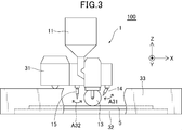
- FIG. 3 shows a schematic configuration diagram of a laminated member manufacturing apparatus 100 to which the metal laminating apparatus 1 is applied. Specifically, FIG. 3 shows a side view of the laminated member manufacturing apparatus 100 observed along the length direction of the cylinder that forms the press-contact roll 13 of the metal laminating apparatus 1. For convenience of explanation, FIG. The figure which saw through is shown.
- the “laminated member” corresponds to a member in which the metal 4 is laminated.
- the laminated member manufacturing apparatus 100 mainly includes the metal laminating apparatus 1 described above, a gantry 31 serving as a moving mechanism configured to move the metal laminating apparatus 1, and a workpiece 5. And a heat shielding wall 33 surrounding the press-contact roll 13 and the workpiece 5 of the metal laminating apparatus 1.
- the laminated member manufacturing apparatus 100 can be opened and closed for telescopic covers that cover the upper portion of the heat shielding wall 33, and for loading the work 5 into the apparatus 100 and removing the work 5 from the apparatus 100. You may have an opening part etc.
- the entire metal laminating apparatus 1 is attached to a gantry 31 and is moved by the gantry 31 in the X, Y, and Z directions shown in FIG. Basically, the gantry 31 is used for pressure-welding and laminating the metal 4 over the entire workpiece 5 by the pressure-contacting roll 13 of the metal laminating apparatus 1 (that is, for forming a plurality of layers of the metal 4 on the entire workpiece 5).
- the metal stacking apparatus 1 is moved in the X direction, the Y direction, and the Z direction.
- the scribing processing laser 14 of the metal laminating apparatus 1 is configured to be movable in the Y direction and the Z direction independently of the movement of the entire metal laminating apparatus 1, and is rotatable in the direction of the arrow A31. It is configured. The scribing laser 14 is moved in the Y and Z directions and rotated in the arrow A31 direction so that the scribing process as shown in FIGS. 2A to 2D is realized.
- the melting laser 15 of the metal laminating apparatus 1 is also configured to be movable in the Y direction and the Z direction independently of the movement of the entire metal laminating apparatus 1, and is rotatable in the direction of the arrow A32. It is configured. The melting laser 15 is moved in the Y direction and the Z direction so as to completely melt the metal 4 pressed onto the work 5 by the press roll 13 by irradiating the laser beam, and rotates in the arrow A32 direction. Moved.
- the metal laminating apparatus 1 is moved by the gantry 31 as follows.
- the gantry 31 moves in one direction in the X direction so that the press roll 13 and the like move from the start end to the end of the work 5 in the X direction. It moves toward (right direction in FIG. 3).
- the metal laminating apparatus 1 forms the next layer on the workpiece 5.
- the press roll 13 or the like moves to the start end in the X direction of the workpiece 5
- the gantry 31 is moved in the other direction in the X direction (left direction in FIG. 3).
- the metal laminating apparatus 1 is moved by the gantry 31 downward (that is, the other direction in the Z direction) so that the metal laminating apparatus 1 descends when the press roll 13 or the like reaches the start end of the workpiece 5 in the X direction.
- the gantry 31 moves the gantry 31 in one direction in the X direction (right direction in FIG. 3).
- the metal laminating apparatus 1 is reciprocated in the X direction a plurality of times by the gantry 31, whereby a plurality of metal 4 layers are formed on the work 5, that is, the metal 4 is laminated on the work 5.
- the Rukoto is the metal laminating apparatus 1 reciprocated in the X direction a plurality of times by the gantry 31, whereby a plurality of metal 4 layers are formed on the work 5, that is, the metal 4 is laminated on the work 5.
- the metal laminating apparatus 1 presses the press roll 13 over the entire portion of the workpiece 5 to be stacked in the Y direction. Is moved in the Y direction by the gantry 31 so as to move. For example, the metal laminating apparatus 1 is moved in the Y direction by the gantry 31 each time the movement of the press roll 13 or the like from one end to the other end in the X direction of the workpiece 5 is completed. In this case, the amount of movement of the metal laminating apparatus 1 in the Y direction may be adjusted so that a seam does not appear between the layers of the metal 4 arranged in the Y direction on the workpiece 5.
- the metal laminating apparatus 1 may be fixed and the work 5 may be moved (in this case, the stage 32 on which the work 5 is placed may be moved). In still another example, both the metal laminating apparatus 1 and the workpiece 5 may be moved. In short, the press roll 13, the scribing processing laser 14, the melting laser 15, etc. may move relative to the workpiece 5.
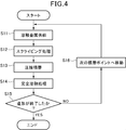
- FIG. 4 is a flowchart showing a method for manufacturing a laminated member according to the first embodiment of the present invention.
- step S ⁇ b> 11 the metal 4 is melted in the melting furnace 11, and the melted metal 4 is supplied to the pressure contact roll 13.
- step S12 the process proceeds to step S12, and a scribing process is performed in which the portion of the metal 4 on the pressure contact roll 13 corresponding to the portion where the metal 4 is not laminated on the work 5 is irradiated with the laser light from the scribing process laser 14.
- step S ⁇ b> 13 the metal 4 in a semi-molten state is pressed and laminated on the work 5 by moving the pressure roll 13 while rotating the pressure roll 13 while the pressure roll 13 is pressed against the work 5.
- step S14 the metal 4 is completely melted by irradiating the laser beam from the melting laser 15 onto the metal 4 pressed onto the work 5 by the press roll 13.
- the metal 4 is completely melted so that the uppermost layer on the workpiece 5 and the lower layer thereof are at least integrated.
- step S15 it is determined whether or not the modeling for the workpiece 5 has been completed.
- finished the manufacturing method of the laminated member by this embodiment is complete
- modeling not complete
- FIG. For example, in order to form the next layer on the work 5, the metal laminating apparatus 1 is moved in the Z direction (upward), and then the metal laminating apparatus 1 is moved to the starting end of the work 5 in the X direction. And it returns to step S11 and performs the process after step S11 mentioned above again.
- the metal 4 in a molten state is supplied from the melting furnace 11 to the pressure contact roll 13 and the metal 4 is pressed and laminated on the work 5 by the pressure contact roll 13.
- the step of melting the raw material (powder) the step of generating powder by atomization, and the step of classifying the powder can be omitted. Therefore, according to 1st Embodiment, the total cost and energy for laminating
- the pressure roll 13 is used to stack the length of the pressure roll 13 with a line, so that the stacking efficiency is higher than the configuration in which the points are stacked as in the prior art. Can be improved.
- the second embodiment is different from the first embodiment in that the ball is used for pressure lamination instead of the pressure roll 13.
- a metal laminating apparatus that performs pressure-contact lamination using a ballpoint pen structure is employed.
- the configuration different from the first embodiment will be mainly described, and the description of the same configuration as the first embodiment will be omitted as appropriate. That is, the configuration that is not particularly described here is the same as that of the first embodiment.
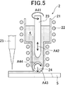
- FIG. 5 shows a schematic configuration diagram of a metal laminating apparatus as a material laminating apparatus according to the second embodiment of the present invention.
- the metal laminating apparatus 2 mainly includes a crucible 21, a heating coil 22, a rotor 23, a ball 24, and a melting laser 25.
- the metal laminating apparatus 2 according to the second embodiment is an apparatus for laminating, for example, a metal 4 such as an aluminum alloy on a workpiece 5 as an object to be laminated.
- the metal laminating apparatus 1 according to the first embodiment is typically applied to a large structure, whereas the metal laminating apparatus 2 according to the second embodiment typically has a complicated shape.
- the target is a relatively small structure.
- the crucible 21 corresponds to a container in which the metal 4 (a molten metal 4) in a semi-molten state is placed.
- the crucible 21 contains an aluminum alloy (Al—Zn—Mg—Cu alloy such as A7075) at about 600 ° C. as the metal 4 in a semi-molten state.
- Al—Zn—Mg—Cu alloy such as A7075
- the “semi-molten state” in the second embodiment corresponds to a state in which the metal material being solidified is mechanically strongly stirred by the rotor and the dentite is divided.
- the heating coil 22 is wound around the outer periphery of the crucible 21 and used for dielectric heating of the crucible 21.
- the rotor 23 is placed in the crucible 21 and operates to stir the metal 4 in the crucible 21 (see arrow A41), and pushes the metal 4 in the crucible 21 toward the ball 24 below. Operates (see arrow A42). The reason why the metal 4 in the crucible 21 is agitated by the rotor 23 is to realize die-casting with less shrinkage and stable quality.
- the ball 24 is a spherical rotating body for pressing and laminating the semi-molten metal 4 on the workpiece 5.
- the ball 24 has a structure similar to that of a ballpoint pen of a general writing instrument, and is rotatably held at a lower end portion of the crucible 21.
- the metal 24 in the crucible 21 is continuously supplied to the ball 24 by the operation of the rotor 23 as shown by the arrow A42.
- the ball 24 is pressed against the workpiece 5 as indicated by an arrow A43 and moves on the workpiece 5 while rotating as indicated by an arrow A44, thereby pressing the supplied metal 4 against the workpiece 5.
- a diameter corresponding to the complexity and size of the stacked object is applied to the diameter of the ball 24.
- the metal 4 in a semi-molten state is put in the crucible 21 and the metal 4 in a semi-molten state is supplied to the ball 24, the relatively low temperature metal 4 is in contact with the ball 24 and members around the ball 24. Will be. Therefore, the balls 24 and members around the balls 24 are not easily consumed.
- the melting laser 25 (only the laser head is shown in FIG. 5) is, for example, a semiconductor laser and irradiates the workpiece 5 with laser light. Specifically, the melting laser 25 irradiates the metal 4 pressed onto the workpiece 5 with the ball 24 with a laser beam, thereby completely melting the metal 4 in a semi-molten state and performing a sintering process. I do.
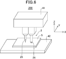
- FIG. 6 is a perspective view showing a schematic configuration of a laminated member manufacturing apparatus 200 to which the metal laminating apparatus 2 is applied.
- the laminated member manufacturing apparatus 200 mainly includes the metal laminating apparatus 2 described above and a gantry 41 that is configured to be able to move the metal laminating apparatus 2 (only a part in FIG. 6). And a stage 42 on which the workpiece 5 is placed.
- the laminated member manufacturing apparatus 200 carries the heat shielding wall that surrounds the balls 24 and the work 5 of the metal laminating apparatus 2, the telescopic cover that covers the upper part of the heat shielding wall, and the work 5 into the apparatus 200. Or an openable / closable opening for removing the workpiece 5 from the apparatus 200.
- the entire metal laminating apparatus 2 is attached to a gantry 41, and is moved by the gantry 41 in the X direction, Y direction (roll direction) and Z direction shown in FIG. Basically, the gantry 41 presses the metal 4 over the entire portion of the workpiece 5 to be stacked by the balls 24 of the metal stacking apparatus 2 and presses the metal 4 pressed on the workpiece 5 by the balls 24.
- the metal laminating apparatus 2 is moved in the X direction and the Y direction in order to form a plurality of layers of the metal 4 on the work 5 by irradiating the laser beam from the melting laser 25 of the metal laminating apparatus 2 and completely melting it.
- the metal laminating apparatus 2 may be fixed and the work 5 may be moved (in this case, the stage 42 on which the work 5 is placed may be moved). In still another example, both the metal laminating apparatus 2 and the workpiece 5 may be moved. In short, the ball 24 and the melting laser 25 may be moved relative to the workpiece 5.
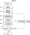
- FIG. 7 is a flowchart showing a method for manufacturing a laminated member according to the second embodiment of the present invention.
- step S21 the metal 4 to be laminated on the workpiece 5 is supplied to the crucible 21. Subsequently, the process proceeds to step S22, in which the heating coil 22 is energized to dielectrically heat the crucible 21, thereby bringing the metal 4 in the crucible 21 into a semi-molten state and rotating the rotor 23 (see arrow A41 in FIG. 5). ) The metal 4 in the crucible 21 is stirred. Next, the process proceeds to step S23, and the metal 4 in the semi-molten state in the crucible 21 is supplied to the ball 24 by moving the rotor 23 in the vertical direction (see arrow A42 in FIG. 5).
- step S24 the process proceeds to step S24, and in a state where the ball 24 is pressed against the work 5, the metal 24 in a semi-molten state is pressed and laminated on the work 5 by moving the ball 24 while rotating the ball 24.
- step S25 the metal 4 pressed onto the workpiece 5 by the ball 24 is irradiated with laser light from the melting laser 25, whereby the metal 4 is completely melted.
- step S26 it is determined whether or not the modeling for the workpiece 5 is completed.
- finished the manufacturing method of the laminated member by this embodiment is complete
- finished it progresses to step S27 and moves the metal lamination
- the metal 4 in a semi-molten state is supplied to the ball 24, and this metal 4 is pressed and laminated to the workpiece 5 by the ball 24. Therefore, the lamination is performed using powder as in the prior art. Compared with the structure to be performed, the step of melting the raw material (powder), the step of generating the powder by atomization, and the step of classifying the powder can be omitted. Therefore, according to 2nd Embodiment, the total cost and energy for laminating
- the pressure contact lamination is performed using the balls 24 having a smaller area in contact with the work 5 than the pressure contact roll 13 shown in the first embodiment, so that the shape is more complicated than that of the first embodiment.
- This is advantageous in the case of performing pressure-contact lamination on an object to be laminated.
- 2nd Embodiment is not limited to the lamination
- the present invention can also be applied to a large-sized laminated object.
- the gantry 31, 41 is shown as a moving mechanism for moving the metal laminating apparatuses 1 and 2, but the gantry 31, 41 is not limited to being used as the moving mechanism, and other publicly known gantry 31, 41 are available. Various moving mechanisms may be used. Moreover, it is not limited to only the structure which moves the metal lamination apparatuses 1 and 2 like the gantry 31 and 41 as a moving mechanism, You may include a motor and a control apparatus (computer etc.) in a moving mechanism.
- the aluminum alloy is exemplified as the metal 4 laminated on the workpiece 5, but the present invention can be applied to various metal materials such as iron, copper, and titanium in addition to the aluminum alloy.
- the present invention can be applied not only to metal materials but also to ceramics.
Landscapes
- Engineering & Computer Science (AREA)
- Physics & Mathematics (AREA)
- Optics & Photonics (AREA)
- Mechanical Engineering (AREA)
- Chemical & Material Sciences (AREA)
- Plasma & Fusion (AREA)
- Manufacturing & Machinery (AREA)
- Materials Engineering (AREA)
- Chemical Kinetics & Catalysis (AREA)
- Metallurgy (AREA)
- Organic Chemistry (AREA)
- Laser Beam Processing (AREA)
- Coating With Molten Metal (AREA)
- Other Surface Treatments For Metallic Materials (AREA)
Applications Claiming Priority (2)
| Application Number | Priority Date | Filing Date | Title |
|---|---|---|---|
| JP2014069697A JP6305807B2 (ja) | 2014-03-28 | 2014-03-28 | 物質積層装置及び積層部材の製造方法 |
| JP2014-069697 | 2014-03-28 |
Publications (1)
| Publication Number | Publication Date |
|---|---|
| WO2015146662A1 true WO2015146662A1 (ja) | 2015-10-01 |
Family
ID=54195185
Family Applications (1)
| Application Number | Title | Priority Date | Filing Date |
|---|---|---|---|
| PCT/JP2015/057639 Ceased WO2015146662A1 (ja) | 2014-03-28 | 2015-03-16 | 物質積層装置及び積層部材の製造方法 |
Country Status (2)
| Country | Link |
|---|---|
| JP (1) | JP6305807B2 (https=) |
| WO (1) | WO2015146662A1 (https=) |
Families Citing this family (3)
| Publication number | Priority date | Publication date | Assignee | Title |
|---|---|---|---|---|
| KR101814282B1 (ko) * | 2016-05-31 | 2018-01-02 | 한양대학교 에리카산학협력단 | 3d 프린터의 노즐 시스템 |
| KR101956918B1 (ko) * | 2017-06-05 | 2019-06-19 | 주식회사 정록 | 3d 프린터용 토출기 |
| CN111979508B (zh) * | 2020-06-23 | 2022-03-01 | 中北大学 | 一种废铝回收直接成形装置及方法 |
Citations (6)
| Publication number | Priority date | Publication date | Assignee | Title |
|---|---|---|---|---|
| JPH0488157A (ja) * | 1990-07-30 | 1992-03-23 | Matsushita Electric Ind Co Ltd | 半田コート装置および半田コート方法 |
| JPH11509375A (ja) * | 1995-12-01 | 1999-08-17 | パック テック―パッケージング テクノロジーズ ゲゼルシャフト ミット ベシュレンクテル ハフツンク | 基板またはチップにフラックスなしで半田付けする方法および装置 |
| JP2000088469A (ja) * | 1998-09-11 | 2000-03-31 | Harima Ceramic Co Ltd | 不定形耐火物の湿式吹き付け装置 |
| JP2001219108A (ja) * | 2000-02-09 | 2001-08-14 | Japan Steel Works Ltd:The | 糊付装置および糊付け方法 |
| JP2004288350A (ja) * | 2003-03-03 | 2004-10-14 | Shinka Jitsugyo Kk | 磁気ヘッド装置の製造方法及び製造装置、並びに磁気ヘッド装置 |
| JP2007128574A (ja) * | 2005-11-01 | 2007-05-24 | Alps Electric Co Ltd | 磁気ヘッドアッセンブリ及びその半田接合方法 |
-
2014
- 2014-03-28 JP JP2014069697A patent/JP6305807B2/ja not_active Expired - Fee Related
-
2015
- 2015-03-16 WO PCT/JP2015/057639 patent/WO2015146662A1/ja not_active Ceased
Patent Citations (6)
| Publication number | Priority date | Publication date | Assignee | Title |
|---|---|---|---|---|
| JPH0488157A (ja) * | 1990-07-30 | 1992-03-23 | Matsushita Electric Ind Co Ltd | 半田コート装置および半田コート方法 |
| JPH11509375A (ja) * | 1995-12-01 | 1999-08-17 | パック テック―パッケージング テクノロジーズ ゲゼルシャフト ミット ベシュレンクテル ハフツンク | 基板またはチップにフラックスなしで半田付けする方法および装置 |
| JP2000088469A (ja) * | 1998-09-11 | 2000-03-31 | Harima Ceramic Co Ltd | 不定形耐火物の湿式吹き付け装置 |
| JP2001219108A (ja) * | 2000-02-09 | 2001-08-14 | Japan Steel Works Ltd:The | 糊付装置および糊付け方法 |
| JP2004288350A (ja) * | 2003-03-03 | 2004-10-14 | Shinka Jitsugyo Kk | 磁気ヘッド装置の製造方法及び製造装置、並びに磁気ヘッド装置 |
| JP2007128574A (ja) * | 2005-11-01 | 2007-05-24 | Alps Electric Co Ltd | 磁気ヘッドアッセンブリ及びその半田接合方法 |
Also Published As
| Publication number | Publication date |
|---|---|
| JP6305807B2 (ja) | 2018-04-04 |
| JP2015190031A (ja) | 2015-11-02 |
Similar Documents
| Publication | Publication Date | Title |
|---|---|---|
| US12214423B2 (en) | High-energy beam additive manufacturing forming device and forming method | |
| US9844913B2 (en) | Method and apparatus for producing three-dimensional objects | |
| JP7002142B2 (ja) | 付加製造過程で部品の変形及び精度を並行制御する方法 | |
| US20160228991A1 (en) | Acoustic manipulation and laser processing of particles for repair and manufacture of metallic components | |
| JP6305807B2 (ja) | 物質積層装置及び積層部材の製造方法 | |
| CN107598358B (zh) | 一种通过消耗型搅拌摩擦工具增材制造的方法 | |
| TW201736028A (zh) | 利用積層製造製備金屬部件 | |
| WO2016070778A1 (zh) | 金属构件电熔成形方法 | |
| US12447557B2 (en) | Laser treatment systems and methods for in-situ Laser Shock Peening (LSP) treatment of parts during production thereof by a Selective Laser Sintering or Melting (SLS/SLM) process, and additive manufacturing systems and methods implementing the same | |
| CN105500720A (zh) | 一种适用于多材料多工艺3d打印方法及所用的打印装置 | |
| WO2016070776A1 (zh) | 核电站压力容器筒体电熔成形方法 | |
| CN115255386B (zh) | 一种保护仓内外增材制造与激光冲击强化复合制造方法 | |
| CN104438323A (zh) | 一种双物理场辅助单面金属层状复合板的制备方法 | |
| KR20150113150A (ko) | 슬래그 제거 장치 및 방법 | |
| CN111558810A (zh) | 一种增减材和激光冲击强化复合的金属丝材增材制造工艺 | |
| JPS6055223B2 (ja) | 肉盛溶接方法 | |
| CN109759584A (zh) | 一种铜铬合金零件的激光选区熔化成形方法 | |
| KR20170140290A (ko) | 튜브형 물품을 제조하기 위한 방법 | |
| KR20100061729A (ko) | 전기 에너지 저장 어셈블리를 제조하는 방법 및 장치 | |
| Streek et al. | Laser micro sintering–a quality leap through improvement of powder packing | |
| CN108384938B (zh) | 一种增材制造中随形约束辊轧细化晶粒的方法和装置 | |
| Qian et al. | Direct rapid high-temperature alloy prototyping by hybrid plasma-laser technology | |
| US20120171507A1 (en) | Electrolytic machining method and semifinished workpiece by the electrolytic machining method | |
| JP5188364B2 (ja) | レーザ加工方法 | |
| JP2015190031A5 (https=) |
Legal Events
| Date | Code | Title | Description |
|---|---|---|---|
| 121 | Ep: the epo has been informed by wipo that ep was designated in this application |
Ref document number: 15769177 Country of ref document: EP Kind code of ref document: A1 |
|
| NENP | Non-entry into the national phase | ||
| 122 | Ep: pct application non-entry in european phase |
Ref document number: 15769177 Country of ref document: EP Kind code of ref document: A1 |