WO2015146315A1 - 全固体電池 - Google Patents
全固体電池 Download PDFInfo
- Publication number
- WO2015146315A1 WO2015146315A1 PCT/JP2015/053455 JP2015053455W WO2015146315A1 WO 2015146315 A1 WO2015146315 A1 WO 2015146315A1 JP 2015053455 W JP2015053455 W JP 2015053455W WO 2015146315 A1 WO2015146315 A1 WO 2015146315A1
- Authority
- WO
- WIPO (PCT)
- Prior art keywords
- solid
- state battery
- electrode layer
- negative electrode
- battery according
- Prior art date
- Legal status (The legal status is an assumption and is not a legal conclusion. Google has not performed a legal analysis and makes no representation as to the accuracy of the status listed.)
- Ceased
Links
Images

Classifications
-
- H—ELECTRICITY
- H01—ELECTRIC ELEMENTS
- H01M—PROCESSES OR MEANS, e.g. BATTERIES, FOR THE DIRECT CONVERSION OF CHEMICAL ENERGY INTO ELECTRICAL ENERGY
- H01M4/00—Electrodes
- H01M4/02—Electrodes composed of, or comprising, active material
- H01M4/13—Electrodes for accumulators with non-aqueous electrolyte, e.g. for lithium-accumulators; Processes of manufacture thereof
- H01M4/131—Electrodes based on mixed oxides or hydroxides, or on mixtures of oxides or hydroxides, e.g. LiCoOx
-
- H—ELECTRICITY
- H01—ELECTRIC ELEMENTS
- H01M—PROCESSES OR MEANS, e.g. BATTERIES, FOR THE DIRECT CONVERSION OF CHEMICAL ENERGY INTO ELECTRICAL ENERGY
- H01M10/00—Secondary cells; Manufacture thereof
- H01M10/05—Accumulators with non-aqueous electrolyte
- H01M10/052—Li-accumulators
- H01M10/0525—Rocking-chair batteries, i.e. batteries with lithium insertion or intercalation in both electrodes; Lithium-ion batteries
-
- H—ELECTRICITY
- H01—ELECTRIC ELEMENTS
- H01M—PROCESSES OR MEANS, e.g. BATTERIES, FOR THE DIRECT CONVERSION OF CHEMICAL ENERGY INTO ELECTRICAL ENERGY
- H01M10/00—Secondary cells; Manufacture thereof
- H01M10/05—Accumulators with non-aqueous electrolyte
- H01M10/056—Accumulators with non-aqueous electrolyte characterised by the materials used as electrolytes, e.g. mixed inorganic/organic electrolytes
- H01M10/0561—Accumulators with non-aqueous electrolyte characterised by the materials used as electrolytes, e.g. mixed inorganic/organic electrolytes the electrolyte being constituted of inorganic materials only
- H01M10/0562—Solid materials
-
- H—ELECTRICITY
- H01—ELECTRIC ELEMENTS
- H01M—PROCESSES OR MEANS, e.g. BATTERIES, FOR THE DIRECT CONVERSION OF CHEMICAL ENERGY INTO ELECTRICAL ENERGY
- H01M10/00—Secondary cells; Manufacture thereof
- H01M10/05—Accumulators with non-aqueous electrolyte
- H01M10/058—Construction or manufacture
- H01M10/0585—Construction or manufacture of accumulators having only flat construction elements, i.e. flat positive electrodes, flat negative electrodes and flat separators
-
- H—ELECTRICITY
- H01—ELECTRIC ELEMENTS
- H01M—PROCESSES OR MEANS, e.g. BATTERIES, FOR THE DIRECT CONVERSION OF CHEMICAL ENERGY INTO ELECTRICAL ENERGY
- H01M4/00—Electrodes
- H01M4/02—Electrodes composed of, or comprising, active material
- H01M4/04—Processes of manufacture in general
- H01M4/0402—Methods of deposition of the material
- H01M4/0414—Methods of deposition of the material by screen printing
-
- H—ELECTRICITY
- H01—ELECTRIC ELEMENTS
- H01M—PROCESSES OR MEANS, e.g. BATTERIES, FOR THE DIRECT CONVERSION OF CHEMICAL ENERGY INTO ELECTRICAL ENERGY
- H01M4/00—Electrodes
- H01M4/02—Electrodes composed of, or comprising, active material
- H01M4/13—Electrodes for accumulators with non-aqueous electrolyte, e.g. for lithium-accumulators; Processes of manufacture thereof
- H01M4/133—Electrodes based on carbonaceous material, e.g. graphite-intercalation compounds or CFx
-
- H—ELECTRICITY
- H01—ELECTRIC ELEMENTS
- H01M—PROCESSES OR MEANS, e.g. BATTERIES, FOR THE DIRECT CONVERSION OF CHEMICAL ENERGY INTO ELECTRICAL ENERGY
- H01M4/00—Electrodes
- H01M4/02—Electrodes composed of, or comprising, active material
- H01M4/13—Electrodes for accumulators with non-aqueous electrolyte, e.g. for lithium-accumulators; Processes of manufacture thereof
- H01M4/139—Processes of manufacture
- H01M4/1391—Processes of manufacture of electrodes based on mixed oxides or hydroxides, or on mixtures of oxides or hydroxides, e.g. LiCoOx
-
- H—ELECTRICITY
- H01—ELECTRIC ELEMENTS
- H01M—PROCESSES OR MEANS, e.g. BATTERIES, FOR THE DIRECT CONVERSION OF CHEMICAL ENERGY INTO ELECTRICAL ENERGY
- H01M4/00—Electrodes
- H01M4/02—Electrodes composed of, or comprising, active material
- H01M4/13—Electrodes for accumulators with non-aqueous electrolyte, e.g. for lithium-accumulators; Processes of manufacture thereof
- H01M4/139—Processes of manufacture
- H01M4/1393—Processes of manufacture of electrodes based on carbonaceous material, e.g. graphite-intercalation compounds or CFx
-
- H—ELECTRICITY
- H01—ELECTRIC ELEMENTS
- H01M—PROCESSES OR MEANS, e.g. BATTERIES, FOR THE DIRECT CONVERSION OF CHEMICAL ENERGY INTO ELECTRICAL ENERGY
- H01M4/00—Electrodes
- H01M4/02—Electrodes composed of, or comprising, active material
- H01M4/36—Selection of substances as active materials, active masses, active liquids
- H01M4/362—Composites
- H01M4/366—Composites as layered products
-
- H—ELECTRICITY
- H01—ELECTRIC ELEMENTS
- H01M—PROCESSES OR MEANS, e.g. BATTERIES, FOR THE DIRECT CONVERSION OF CHEMICAL ENERGY INTO ELECTRICAL ENERGY
- H01M4/00—Electrodes
- H01M4/02—Electrodes composed of, or comprising, active material
- H01M4/36—Selection of substances as active materials, active masses, active liquids
- H01M4/38—Selection of substances as active materials, active masses, active liquids of elements or alloys
- H01M4/381—Alkaline or alkaline earth metals elements
- H01M4/382—Lithium
-
- H—ELECTRICITY
- H01—ELECTRIC ELEMENTS
- H01M—PROCESSES OR MEANS, e.g. BATTERIES, FOR THE DIRECT CONVERSION OF CHEMICAL ENERGY INTO ELECTRICAL ENERGY
- H01M4/00—Electrodes
- H01M4/02—Electrodes composed of, or comprising, active material
- H01M4/36—Selection of substances as active materials, active masses, active liquids
- H01M4/48—Selection of substances as active materials, active masses, active liquids of inorganic oxides or hydroxides
- H01M4/52—Selection of substances as active materials, active masses, active liquids of inorganic oxides or hydroxides of nickel, cobalt or iron
- H01M4/525—Selection of substances as active materials, active masses, active liquids of inorganic oxides or hydroxides of nickel, cobalt or iron of mixed oxides or hydroxides containing iron, cobalt or nickel for inserting or intercalating light metals, e.g. LiNiO2, LiCoO2 or LiCoOxFy
-
- H—ELECTRICITY
- H01—ELECTRIC ELEMENTS
- H01M—PROCESSES OR MEANS, e.g. BATTERIES, FOR THE DIRECT CONVERSION OF CHEMICAL ENERGY INTO ELECTRICAL ENERGY
- H01M4/00—Electrodes
- H01M4/02—Electrodes composed of, or comprising, active material
- H01M4/36—Selection of substances as active materials, active masses, active liquids
- H01M4/58—Selection of substances as active materials, active masses, active liquids of inorganic compounds other than oxides or hydroxides, e.g. sulfides, selenides, tellurides, halogenides or LiCoFy; of polyanionic structures, e.g. phosphates, silicates or borates
- H01M4/583—Carbonaceous material, e.g. graphite-intercalation compounds or CFx
- H01M4/587—Carbonaceous material, e.g. graphite-intercalation compounds or CFx for inserting or intercalating light metals
-
- H—ELECTRICITY
- H01—ELECTRIC ELEMENTS
- H01M—PROCESSES OR MEANS, e.g. BATTERIES, FOR THE DIRECT CONVERSION OF CHEMICAL ENERGY INTO ELECTRICAL ENERGY
- H01M4/00—Electrodes
- H01M4/02—Electrodes composed of, or comprising, active material
- H01M4/62—Selection of inactive substances as ingredients for active masses, e.g. binders, fillers
- H01M4/624—Electric conductive fillers
- H01M4/625—Carbon or graphite
-
- H—ELECTRICITY
- H01—ELECTRIC ELEMENTS
- H01M—PROCESSES OR MEANS, e.g. BATTERIES, FOR THE DIRECT CONVERSION OF CHEMICAL ENERGY INTO ELECTRICAL ENERGY
- H01M4/00—Electrodes
- H01M4/02—Electrodes composed of, or comprising, active material
- H01M2004/021—Physical characteristics, e.g. porosity, surface area
-
- H—ELECTRICITY
- H01—ELECTRIC ELEMENTS
- H01M—PROCESSES OR MEANS, e.g. BATTERIES, FOR THE DIRECT CONVERSION OF CHEMICAL ENERGY INTO ELECTRICAL ENERGY
- H01M2300/00—Electrolytes
- H01M2300/0017—Non-aqueous electrolytes
- H01M2300/0065—Solid electrolytes
- H01M2300/0068—Solid electrolytes inorganic
- H01M2300/0071—Oxides
-
- Y—GENERAL TAGGING OF NEW TECHNOLOGICAL DEVELOPMENTS; GENERAL TAGGING OF CROSS-SECTIONAL TECHNOLOGIES SPANNING OVER SEVERAL SECTIONS OF THE IPC; TECHNICAL SUBJECTS COVERED BY FORMER USPC CROSS-REFERENCE ART COLLECTIONS [XRACs] AND DIGESTS
- Y02—TECHNOLOGIES OR APPLICATIONS FOR MITIGATION OR ADAPTATION AGAINST CLIMATE CHANGE
- Y02E—REDUCTION OF GREENHOUSE GAS [GHG] EMISSIONS, RELATED TO ENERGY GENERATION, TRANSMISSION OR DISTRIBUTION
- Y02E60/00—Enabling technologies; Technologies with a potential or indirect contribution to GHG emissions mitigation
- Y02E60/10—Energy storage using batteries
-
- Y—GENERAL TAGGING OF NEW TECHNOLOGICAL DEVELOPMENTS; GENERAL TAGGING OF CROSS-SECTIONAL TECHNOLOGIES SPANNING OVER SEVERAL SECTIONS OF THE IPC; TECHNICAL SUBJECTS COVERED BY FORMER USPC CROSS-REFERENCE ART COLLECTIONS [XRACs] AND DIGESTS
- Y02—TECHNOLOGIES OR APPLICATIONS FOR MITIGATION OR ADAPTATION AGAINST CLIMATE CHANGE
- Y02P—CLIMATE CHANGE MITIGATION TECHNOLOGIES IN THE PRODUCTION OR PROCESSING OF GOODS
- Y02P70/00—Climate change mitigation technologies in the production process for final industrial or consumer products
- Y02P70/50—Manufacturing or production processes characterised by the final manufactured product
Definitions
- the present invention relates to an all solid state battery including a carbon material in a negative electrode layer.
- a liquid electrolyte such as an organic solvent using a flammable organic solvent as a diluent solvent has been conventionally used as a medium for moving ions.
- a battery using such an electrolytic solution may cause problems such as leakage of the electrolytic solution, ignition, and explosion.
- Japanese Patent Application Laid-Open No. 2011-187253 describes an example using a mixture of a negative electrode active material and a solid electrolyte material as a negative electrode material, graphite as a negative electrode active material, and a sulfide-based solid electrolyte material as a solid electrolyte material. Yes. And a negative electrode is produced by pressure-molding the said mixture.
- Japanese Patent Application Laid-Open No. 2009-187682 describes a thin film solid lithium ion secondary battery provided with a lithium cobalt oxide thin film and a nitrogen-substituted lithium phosphate thin film, and in particular, a magnetron sputtered 2 ⁇ m lithium cobalt oxide thin film as a cathode electrode. It is described that it is formed by a method.
- the negative electrode described in Japanese Patent Application Laid-Open No. 2011-187253 is produced by pressure-molding a mixture of graphite (negative electrode active material) and a sulfide-based solid electrolyte material.
- a sulfide-based solid electrolyte material is soft, a low-resistance interface between the electrode and the solid electrolyte can be formed relatively easily by pressure molding or the like.
- the oxide-based solid electrolyte material is hard, the electrode-solid electrolyte interface tends to increase in resistance.
- a physical vapor deposition method such as sputtering can be cited.
- the secondary battery described in Japanese Patent Application Laid-Open No. 2009-187682 using the sputtering method has a negative electrode layer thickness of only 2 ⁇ m. Therefore, the capacity cannot be increased.
- the present invention has been made in consideration of such problems, and an object of the present invention is to provide an all solid state battery capable of reducing the negative electrode interface resistance and increasing the capacity per unit area.
- the all solid state battery according to the present invention is an all solid state battery having at least a positive electrode layer, a negative electrode layer, and a solid electrolyte layer interposed between the positive electrode layer and the negative electrode layer, It is a film containing at least one kind of carbon material, and the film thickness of the negative electrode layer is 3 ⁇ m or more.
- carbon material 1 one type of carbon material is referred to as “carbon material 1”.
- the porosity of the negative electrode layer may be 20% or less.
- the specific surface area of the carbon material 1 contained in the negative electrode layer may be 25 m 2 / g or more.
- the carbon material 1 may be carbon black.
- the structure diameter (D50) of carbon black is preferably 500 nm or less.
- the carbon material 1 may be a carbon pulverized powder.
- the particle size (D50) of the carbon pulverized powder is preferably 500 nm or less.
- the carbon material 1 may be a carbon nanotube.
- the carbon nanotube is preferably a multi-walled carbon nanotube.
- the negative electrode layer may include the carbon material 1 and the second component.
- the second component has a higher capacity (mAh / g) than the carbon material 1.
- the second component may be carbon (carbon material 2).
- the second component may be a material alloyed with lithium.
- an intermediate layer may be provided between the negative electrode layer and the solid electrolyte layer.
- the intermediate layer may have a metal alloying with lithium.
- the positive electrode layer may be composed of only a positive electrode active material in which a specific crystal plane is oriented in the lithium ion conduction direction.
- the positive electrode active material may have a layered rock salt structure of LiCoO 2 particles, and the specific crystal plane may be a (003) plane.
- the specific crystal plane may be a (003) plane.
- the solid electrolyte layer may have a garnet-based crystal structure containing Li 7 La 3 Zr 2 O 12 .
- the solid electrolyte layer may include LiPON obtained by nitriding a part of Li 3 PO 4 .
- the all solid state battery according to the present invention can reduce the negative electrode interface resistance and increase the capacity per unit area.
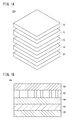
- FIG. 1A is an exploded perspective view showing the main part of the all solid state battery (first all solid state battery) according to the first embodiment
- FIG. 1B is a longitudinal sectional view showing the main part of the first all solid state battery. is there.
- FIG. 2 is a longitudinal sectional view showing a main part of the all solid state battery (second all solid state battery) according to the second embodiment.
- the all solid state battery according to the first embodiment includes at least a positive electrode layer 12, a negative electrode layer 14, and a positive electrode layer 12. And a solid electrolyte layer 16 interposed between the negative electrode layer 14 and the negative electrode layer 14.
- a positive electrode current collector 18 is stacked on the end surface (for example, the upper surface) of the positive electrode layer 12, and a negative electrode current collector 20 is stacked on the end surface (for example, the lower surface) of the negative electrode layer 14.
- the first all-solid-state battery 10A is configured by laminating the positive electrode current collector 18, the positive electrode layer 12, the solid electrolyte layer 16, the negative electrode layer 14, and the negative electrode current collector 20 from the positive electrode toward the negative electrode.
- the positive electrode current collector 18 and the negative electrode current collector 20 are each composed of, for example, a metal foil (aluminum foil, copper foil, etc.).
- the positive electrode layer 12 can use a commonly used positive electrode active material. Moreover, it can also comprise using the positive electrode active material in which the specific crystal plane orientated in the lithium ion conduction direction.
- the positive electrode layer 12 is composed of a layer in which a specific crystal plane of each particle is oriented in a direction from the positive electrode layer 12 to the negative electrode layer 14, and the specific crystal plane is lithium. Only particles (positive electrode active material) oriented in the ion conduction direction are sintered.
- the positive electrode active material has a layered rock salt structure or a spinel structure.
- LiCoO 2 particles that are formed in a plate shape with a thickness of about 2 to 100 ⁇ m are preferred.
- the specific crystal plane described above is a (003) plane, and the (003) plane is preferably oriented in a direction from the positive electrode layer 12 to the negative electrode layer 14.
- particles having a composition represented by the following general formula and having a thickness of about 2 to 100 ⁇ m are preferable.
- General formula: Li p (Ni x Co y Al z ) O 2 (In the above general formula, 0.9 ⁇ p ⁇ 1.3, 0.6 ⁇ x ⁇ 0.9, 0.1 ⁇ y ⁇ 0.3, 0 ⁇ z ⁇ 0.2, x + y + z 1)
- the above-mentioned specific crystal plane is the (003) plane, and the (003) plane is oriented in the direction from the positive electrode layer 12 to the negative electrode layer 14.
- the solid electrolyte layer 16 is preferably an oxide-based solid electrolyte that is safe even when exposed to the atmosphere.
- the oxide solid electrolyte preferably includes a garnet-based or garnet-like crystal structure containing Li (lithium), La (lanthanum), Zr (zirconium), and O (oxygen).
- a garnet-based crystal structure containing Li 7 La 3 Zr 2 O 12 (LLZ) can be used.
- Li lithium
- P phosphorus
- O oxygen
- N nitrogen
- LiPON obtained by nitriding a part of Li 3 PO 4 can be used.
- the negative electrode layer 14 is a film containing at least one carbon material, and preferably has a film thickness of 3 ⁇ m or more and a porosity of 20% or less.
- the specific surface area of the carbon material (hereinafter referred to as carbon material 1) contained in the negative electrode layer 14 is preferably 25 m 2 / g or more.
- Examples of the carbon material 1 include carbon black, carbon pulverized powder, and carbon nanotube.
- the structure diameter (D50) of carbon black is preferably 500 nm or less.
- the particle size (D50) of the pulverized carbon powder is preferably 500 nm or less.
- carbon nanotubes single-walled carbon nanotubes or multi-walled carbon nanotubes may be used.
- a multi-walled carbon nanotube is preferable.
- the negative electrode layer 14 may include the carbon material 1 and the second component described above.
- the second component preferably has a higher capacity (mAh / g) than the carbon material 1.
- Examples of the second component include carbon (carbon material 2) or a material that forms an alloy with lithium.
- Examples of the carbon material 2 include soft carbon.
- the above-mentioned carbon black refers to submicron fine particles produced by industrially quality control.
- Soft carbon that is easily graphitized when subjected to high-temperature heat treatment is called soft carbon.
- a carbon nanotube is a fine cylindrical material having a diameter of several to several nanometers.
- Examples of materials to be alloyed with lithium include Al (aluminum), Si (silicon), Zn (zinc), Ga (gallium), Ge (germanium), Ag (silver), Au (gold), Cd (cadmium), Examples include In (indium), Sn (tin), Sb (antimony), Pb (lead), and Bi (bismuth). Further, the metal alloyed with lithium includes an alloy composed of two or more elements such as Mg 2 Si and Mg 2 Sn.
- the negative electrode layer 14 is formed of a film containing at least one kind of carbon material, and the film thickness is 3 ⁇ m or more, so that a high capacity can be realized.
- the porosity of the negative electrode layer 14 is set to 20% or less, the negative electrode layer 14 becomes dense and the capacity per unit area can be increased.
- the specific surface area of the carbon material 1 contained in the negative electrode layer 14 is 25 m 2 / g or more. That is, since the particle diameter of the carbon material is small and a fine carbon material is used, the interface resistance (negative electrode interface resistance) with the solid electrolyte layer 16 can be reduced. Since the negative electrode layer 14 is a film using a carbon material having a small particle size, the negative electrode layer 14 is easily densified, and a high energy density can be obtained.
- an all solid state battery (hereinafter referred to as a second all solid state battery) according to the second embodiment will be described with reference to FIG.
- the second all solid state battery 10B has substantially the same configuration as the first all solid state battery 10A described above, but differs in that an intermediate layer 22 is provided between the negative electrode layer 14 and the solid electrolyte layer 16.
- the above-described material alloyed with lithium can be used as the material constituting the intermediate layer 22.
- Particle size The powder to be measured was dispersed in water, and the average particle diameter (D50) was measured with a laser diffraction / scattering particle size distribution measuring apparatus (Microtrack MT3300EXII manufactured by NIKKISO). “Particle size” corresponds to this average particle size (D50).
- This operation was performed in three fields of view arbitrarily extracted from the negative electrode layer 14, and the average value was defined as the porosity.
- Nitrogen was measured as an adsorption gas using the BET method.
- the specific surface area of the carbon material, carbon black is 240 m 2 / g, the multi-walled carbon nanotube was 90m 2 / g. Since amorphous carbon was not powder, it could not be measured.
- the capacity per unit area indicates the value obtained by dividing the charge capacity of the first cycle by the cell area.
- [Positive electrode layer 12] (A) Positive electrode layer 12 using LiCoO 2 particles A green sheet having a thickness of 20 ⁇ m or less containing Co 3 O 4 and Bi 2 O 3 is formed. This green sheet is fired at a temperature in the range of 900 to 1300 ° C. for a predetermined time, so that it is an independent thin film sheet composed of a large number of plate-like Co 3 O 4 particles oriented (h00) in the particle plate surface direction. (Self-supporting film) is formed.
- “(h00) orientation” indicates that the (h00) plane is oriented so as to be parallel to the plate surface.
- bismuth is volatilized and removed from the sheet, and Co 3 O 4 is reduced to phase change to CoO.
- the “independent” sheet refers to a sheet that can be handled as a single unit independently of other supports after firing. That is, the “independent” sheet does not include a sheet that is fixed to another support (substrate or the like) by firing and integrated with the support (unseparable or difficult to separate).
- the amount of material existing in the thickness direction is extremely small compared to the particle plate surface direction, that is, the in-plane direction (direction perpendicular to the thickness direction). Few.
- the grain growth direction is limited to the in-plane two-dimensional direction. This reliably promotes grain growth in the surface direction.
- the green sheet as thin as possible (for example, several ⁇ m or less), or by promoting the grain growth as much as possible even if the thickness is about 100 ⁇ m (for example, about 20 ⁇ m).
- the grain growth in the surface direction is more reliably promoted.
- the degree of orientation tends to decrease. This is because the distance between atoms in the crystal structure and CoO in CoO and Co 3 O 4 are significantly different, oxide, i.e., when the oxygen atom is inserted, because the crystal structure is easily disturbed. Therefore, it is preferable to select conditions appropriately so as not to reduce the degree of orientation as much as possible. For example, it is preferable to reduce the rate of temperature decrease, hold at a predetermined temperature, or reduce the oxygen partial pressure.
- a thin film (self-supporting film) in which a large number of thin plate-like particles whose specific crystal planes are oriented in the grain plate surface direction is bonded in the plane direction at the grain boundary portion is obtained. That is, a thin film (self-supporting film) is formed in which the number of crystal grains in the thickness direction is substantially one.
- the meaning of “substantially one crystal grain in the thickness direction” does not exclude that a part (for example, end portions) of crystal grains adjacent in the plane direction overlap each other in the thickness direction.
- This self-supporting film can be a dense ceramic sheet in which a large number of thin plate-like particles as described above are bonded without gaps.
- Lithium is introduced into the Co 3 O 4 particles by mixing the (h00) -oriented Co 3 O 4 ceramic sheet obtained by the above process and Li 2 CO 3 and heating the mixture for a predetermined time.
- a film-like sheet for the positive electrode layer 12 having the (003) plane oriented in the direction from the positive electrode layer 12 to the negative electrode layer 14 and the (104) plane oriented along the plate surface is obtained.
- This self-supporting film can be a dense ceramic sheet in which a large number of thin plate-like particles as described above are bonded without gaps.
- the (h00) -oriented (Ni, Co, Al) O ceramic sheet obtained by the above-mentioned process and lithium nitrate (LiNO 3 ) are mixed and heated for a predetermined time, thereby (Ni, Co, Al). ) Lithium is introduced into the O particles.
- An O 2 sheet is obtained.
- the negative electrode layer 14 can be formed by various known printing methods, but is preferably performed by a screen printing method.
- the printing paste was prepared by appropriately adding a binder resin and a solvent to the carbon material and mixing them.
- a binder resin include acrylic resins, PVDF (polyvinylidene fluoride), PTFE (polytetrafluoroethylene), SBR (styrene butadiene rubber), polyimide resins, polystyrene resins, and the like.
- the solvent include N-methylpyrrolidone (NMP), water, alcohols such as terpineol, acetates such as butyl acetate, and methyl ethyl ketone.
- the negative electrode paste is printed on the solid electrolyte layer 16 or the intermediate layer 22 so as to have a desired film thickness, and dried at 80 to 300 ° C. to form the negative electrode layer 14. If necessary, the negative electrode layer 14 may be formed on the solid electrolyte layer 16 or the intermediate layer 22 and then heat treatment may be performed.
- the atmosphere for the heat treatment is preferably a vacuum atmosphere or an inert atmosphere.
- the heat treatment temperature is preferably 300 to 800 ° C.
- Solid electrolyte layer 16 (A) Solid electrolyte layer 16 using LLZ First, in the first firing step, a raw material containing a Li component, a La component and a Zr component is fired to obtain a primary fired powder for ceramic synthesis containing Li, La, Zr and oxygen. Li 2 CO 3 or LiOH can be used as the Li component, La (OH) 3 or La 2 O 3 can be used as the La component, and ZrO 2 can be used as the Zr component.
- the first firing step is a step of obtaining a primary fired powder for facilitating the thermal decomposition of at least the Li component and the La component to easily form the LLZ crystal structure in the second firing step.
- the primary fired powder may already have an LLZ crystal structure.
- the firing temperature is preferably 850 ° C. or higher and 1150 ° C. or lower.
- the primary fired powder obtained in the first firing step is fired at a temperature of 950 ° C. to 1250 ° C., and a garnet-based or garnet-like crystal containing Li, La, Zr, and oxygen A ceramic powder having a structure is synthesized. Thereby, it is possible to easily obtain a ceramic powder or sintered body having a LLZ crystal structure and having sinterability (density) and conductivity that contains aluminum and can be handled.
- the second firing step may be carried out after forming the primary fired powder into a molded body having a desired three-dimensional shape (for example, a shape and size that can be used as a solid electrolyte of an all-solid secondary battery). preferable.
- the ceramic powder obtained in the second firing step may be used as a compact, and the compact may be separately subjected to a sintering step at a temperature similar to the heating temperature in the second firing step.
- a sintering step at a temperature similar to the heating temperature in the second firing step.
- various particle jet coating methods, solid phase methods, solution methods, gas phase methods, and direct bonding (direct bonding) methods can be used.
- the particle jet coating method include an aerosol deposition (AD) method, a gas deposition (GD) method, a powder jet deposition (PJD) method, a cold spray (CS) method, and a thermal spraying method.
- the aerosol deposition (AD) method is particularly preferable because it can form a film at room temperature, and does not cause a composition shift during the process or formation of a high resistance layer due to a reaction with the positive electrode plate.
- the solid phase method include a tape lamination method and a printing method.
- the tape lamination method is preferable because the solid electrolyte layer 16 can be formed thin and the thickness can be easily controlled.
- the solution method include a hydrothermal synthesis method, a sol-gel method, a precipitation method, a microemulsion method, and a solvent evaporation method.
- the hydrothermal synthesis method is particularly preferable in that it is easy to obtain crystal grains having high crystallinity at a low temperature.
- microcrystals synthesized using these methods may be deposited on the positive electrode or may be directly deposited on the positive electrode.
- the gas phase method examples include laser deposition (PLD) method, sputtering method, evaporation condensation (PVD) method, gas phase reaction method (CVD) method, vacuum deposition method, molecular beam epitaxy (MBE) method and the like.
- the laser deposition (PLD) method is particularly preferable because there is little composition deviation and a film with relatively high crystallinity can be easily obtained.
- the direct bonding (direct bonding) method is a method in which the surfaces of the solid electrolyte layer 16 and the positive electrode layer 12 formed in advance are chemically activated and bonded at a low temperature. For activation of the interface, plasma or the like may be used, or chemical modification of a functional group such as a hydroxyl group may be used.
- LiPON lithium phosphate oxynitride
- N 2 atmosphere As a method for forming the LiPON film, various sputtering methods can be used. LiPON (lithium phosphate oxynitride) can be formed by setting a Li 3 PO 4 target and a positive electrode plate in the apparatus and applying high frequency power in an N 2 atmosphere.
- the intermediate layer 22 can be formed by various physical vapor deposition (PVD) methods such as a vacuum deposition method and a sputtering method.
- PVD physical vapor deposition
- the intermediate layer 22 can be formed by setting the target of the intermediate layer material and the solid electrolyte layer 16 in the apparatus and depositing the intermediate layer material on the solid electrolyte layer 16.
- the intermediate layer material is a material that forms an alloy with lithium described above.
- the negative electrode interface resistance and the capacity per unit area were confirmed for Examples 1 to 11 and Comparative Examples 1 and 2, and the negative electrode interface resistance and the capacity per unit weight of the positive electrode were determined for Examples 12 and 13. confirmed.
- Example 1 Referred to as "LLZ" Carbon black (average particle size (structure size) is 0.45 [mu] m), a binder and a solvent appropriately mixed paste, the solid electrolyte layer 16 (Table 1 using the Li 7 La 3 Zr 2 O 12
- the negative electrode layer 14 was formed by printing at 200 ° C. and drying at 200 ° C.
- a Li metal layer was formed by thermocompression bonding. That is, in order to confirm the performance of only the negative electrode layer 14, a half cell having a Li metal layer as a counter electrode was formed.
- the porosity of the negative electrode layer 14 was 12%, and the film thickness of the negative electrode layer 14 was 22 ⁇ m.
- Example 2 A battery according to Example 2 was produced in the same manner as in Example 1 except that an Au (gold) intermediate layer 22 (about 300 nm thick) was formed between the solid electrolyte layer 16 and the negative electrode layer 14 by sputtering. .
- the porosity of the negative electrode layer 14 was 10%, and the film thickness of the negative electrode layer 14 was 13 ⁇ m.
- Example 3 A battery according to Example 3 was fabricated in the same manner as in Example 2 except that the intermediate layer 22 and the negative electrode layer 14 were formed on the solid electrolyte layer 16 and then heat-treated in a vacuum atmosphere at 400 ° C. to carbonize the binder.
- the porosity of the negative electrode layer 14 was 15%, and the film thickness of the negative electrode layer 14 was 26 ⁇ m.
- Example 4 A battery according to Example 4 was fabricated in the same manner as in Example 2 except that the negative electrode layer 14 was formed of a paste obtained by mixing carbon black and a solvent. The porosity of the negative electrode layer 14 was 11%, and the film thickness of the negative electrode layer 14 was 4 ⁇ m.
- Example 5 A battery according to Example 5 was made in the same manner as Example 2 except that the porosity of the negative electrode layer 14 was 8% and the thickness of the negative electrode layer 14 was 10 ⁇ m.
- Example 6 A battery according to Example 6 was made in the same manner as Example 2 except that the porosity of the negative electrode layer 14 was 9% and the thickness of the negative electrode layer 14 was 14 ⁇ m.
- Example 7 A battery according to Example 7 was fabricated in the same manner as in Example 2 except that multi-walled carbon nanotubes having a length in the longitudinal direction of 2 ⁇ m (indicated as “multilayer CNT” in Table 1) were used as the carbon material.
- the porosity of the negative electrode layer 14 was 14%, and the film thickness of the negative electrode layer 14 was 27 ⁇ m.
- Example 8 A battery according to Example 8 was fabricated in the same manner as in Example 2 except that 33% by mass of soft carbon having an average particle diameter of 2 ⁇ m was included as the second component in addition to carbon black in the negative electrode layer 14.
- the porosity of the negative electrode layer 14 was 10%, and the film thickness of the negative electrode layer 14 was 12 ⁇ m.
- Example 9 A battery according to Example 9 was made in the same manner as Example 8, except that 50% by mass of soft carbon was included in the negative electrode layer 14 as the second component.
- the porosity of the negative electrode layer 14 was 14%, and the film thickness of the negative electrode layer 14 was 25 ⁇ m.
- Example 10 A battery according to Example 10 was made in the same manner as in Example 8, except that 67% by mass of soft carbon was included in the negative electrode layer 14 as the second component.
- the porosity of the negative electrode layer 14 was 15%, and the film thickness of the negative electrode layer 14 was 15 ⁇ m.
- Example 11 A battery according to Example 11 was produced in the same manner as in Example 4 except that 33% by mass of soft carbon having an average particle diameter of 2 ⁇ m was included as the second component in addition to carbon black in the negative electrode layer 14.
- the porosity of the negative electrode layer 14 was 9%, and the film thickness of the negative electrode layer 14 was 13 ⁇ m.
- Example 12 The negative electrode layer 14 is formed by printing a paste in which carbon black, a binder, and a solvent are mixed on the intermediate layer 22 formed on the solid electrolyte layer 16, and the positive electrode layer 12 is formed by a layer of LiCoO 2 particles (“LCO” in Table 1).
- a battery according to Example 12 was fabricated in the same manner as in Example 2 except that it was configured as “ The porosity of the negative electrode layer 14 was 15%, and the film thickness of the negative electrode layer 14 was 16 ⁇ m.
- Example 13 (Example 13) Implementation was carried out except that a layer made of LiCoO 2 particles whose specific crystal plane (003) was oriented in the direction from the positive electrode layer 12 toward the negative electrode layer 14 (shown as “oriented LCO” in Table 1) was used as the positive electrode layer 12.
- a battery according to Example 13 was made in the same manner as Example 12.
- the porosity of the negative electrode layer 14 was 13%, and the film thickness of the negative electrode layer 14 was 15 ⁇ m.
- Comparative Example 1 A battery according to Comparative Example 1 was produced in the same manner as in Example 1 except that the carbon material of the negative electrode layer 14 was soft carbon having an average particle diameter of 23 ⁇ m. The porosity of the negative electrode layer 14 was 26%, and the film thickness of the negative electrode layer 14 was 21 ⁇ m.
- Comparative Example 2 A battery according to Comparative Example 2 was fabricated in the same manner as in Example 1 except that the negative electrode layer 14 was amorphous carbon (indicated as “amorphous C” in Table 1) formed by vacuum deposition. The porosity of the negative electrode layer 14 was 2%, and the film thickness of the negative electrode layer 14 was 0.5 ⁇ m. In addition, since the negative electrode layer 14 was formed by vapor deposition of amorphous carbon, the particle size of the amorphous carbon was not measurable.
- Table 1 shows the measurement results.
- the negative electrode interface resistance was set to an approximate value, that is, 1.0 ⁇ 10 6 [ohm ⁇ cm 2 ] or more.
- the negative electrode interface resistance was 503 [ohm ⁇ cm 2 ]
- the capacity per unit area was 0.03 [mAh / cm 2 ].
- Example 1 without the intermediate layer 22 had a higher negative electrode interface resistance than Comparative Example 2, but a higher capacity per unit area than Comparative Example 2.
- the film thickness of the negative electrode layer 14 is preferably 3 ⁇ m or more, more preferably 5 ⁇ m, and even more preferably 10 ⁇ m or more. Further, the porosity of the negative electrode layer 14 is preferably 20% or less, more preferably 15% or less, and more preferably 13% or less.
- the all-solid-state battery according to the present invention is not limited to the above-described embodiment, and can of course have various configurations without departing from the gist of the present invention.
Landscapes
- Chemical & Material Sciences (AREA)
- Chemical Kinetics & Catalysis (AREA)
- Electrochemistry (AREA)
- General Chemical & Material Sciences (AREA)
- Engineering & Computer Science (AREA)
- Materials Engineering (AREA)
- Manufacturing & Machinery (AREA)
- Inorganic Chemistry (AREA)
- Composite Materials (AREA)
- Physics & Mathematics (AREA)
- Condensed Matter Physics & Semiconductors (AREA)
- General Physics & Mathematics (AREA)
- Secondary Cells (AREA)
- Battery Electrode And Active Subsutance (AREA)
Abstract
本発明は全固体電池に関する。全固体電池は、少なくとも正極層(12)と、負極層(14)と、正極層(12)と負極層(14)との間に介在された固体電解質層(16)とを有する全固体電池であって、負極層(14)は、少なくとも1種の炭素材料を含む膜であり、負極層(14)の膜厚が3μm以上である。
Description
本発明は、負極層に炭素材料を含む全固体電池に関する。
近年、パーソナルコンピュータ、携帯電話等のポータブル機器の開発に伴い、その電源としての電池の需要が大幅に拡大している。このような用途に用いられる電池においては、イオンを移動させる媒体として、希釈溶媒に可燃性の有機溶媒を用いた有機溶媒等の液体の電解質(電解液)が従来使用されている。このような電解液を用いた電池においては、電解液の漏液や、発火、爆発等の問題を生ずる可能性がある。
このような問題を解消すべく、本質的な安全性確保のために、液体の電解質に代えて固体電解質を使用すると共に、その他の要素の全てを固体で構成した全固体電池の開発が進められている。このような全固体電池は、電解質が固体であることから、発火の心配が少なく、漏液せず、また、腐食による電池性能の劣化等の問題も生じ難い。
従来の全固体電池としては、例えば特開2011-187253号公報及び特開2009-187682号公報に記載の全固体電池が知られている。
特開2011-187253号公報には、負極材として負極活物質と固体電解質材料との混合物を用い、負極活物質としてグラファイト、固体電解質材料として硫化物系固体電解質材料を用いた例が記載されている。そして、負極は、前記混合物を加圧成形することによって作製される。
特開2009-187682号公報には、コバルト酸リチウム薄膜及び窒素置換リン酸リチウム薄膜を設けた薄膜固体リチウムイオン二次電池が記載され、特に、カソード電極として、2μmのコバルト酸リチウム薄膜をマグネトロンスパッタ法により形成することが記載されている。
特開2011-187253号公報に記載の負極は、グラファイト(負極活物質)と硫化物系固体電解質材料との混合物を加圧成形することによって作製している。一般的に、硫化物系固体電解質材料は柔らかいため、加圧成形等で比較的容易に低抵抗な電極・固体電解質間界面を形成することができる。しかし、酸化物系固体電解質材料は硬いため、電極-固体電解質界面が高抵抗化する傾向がある。
また、低抵抗化の手段としてスパッタ等の物理気相成長法が挙げられるが、スパッタ法を用いた特開2009-187682号公報に記載の二次電池は、負極層の膜厚が2μmでしかないため、容量の増大化を図ることができない。
本発明はこのような課題を考慮してなされたものであり、負極界面抵抗の低減化、単位面積当たりの容量の増大化を図ることができる全固体電池を提供することを目的とする。
[1] 本発明に係る全固体電池は、少なくとも正極層と、負極層と、正極層と負極層との間に介在された固体電解質層とを有する全固体電池であって、負極層は、少なくとも1種の炭素材料を含む膜であり、負極層の膜厚が3μm以上であることを特徴とする。以下の説明では、1種の炭素材料を「炭素材料1」と記す。
[2] 本発明において、負極層の気孔率が20%以下であってもよい。
[3] 本発明において、負極層に含まれる炭素材料1の比表面積が25m2/g以上であってもよい。
[4] 本発明において、炭素材料1がカーボンブラックであってもよい。
[5] この場合、カーボンブラックのストラクチャー径(D50)が500nm以下であることが好ましい。
[6] 本発明において、炭素材料1がカーボン粉砕粉であってもよい。
[7] この場合、カーボン粉砕粉の粒径(D50)が500nm以下であることが好ましい。
[8] 本発明において、炭素材料1がカーボンナノチューブであってもよい。
[9] この場合、カーボンナノチューブが多層カーボンナノチューブであることが好ましい。
[10] 本発明において、負極層が炭素材料1と第2成分とを含んでもよい。
[11] この場合、第2成分が炭素材料1より高容量(mAh/g)であることが好ましい。
[12] 第2成分が炭素(炭素材料2)であってもよい。
[13] あるいは、第2成分がリチウムと合金化する材料であってもよい。
[14] 本発明において、負極層と固体電解質層との間に中間層を有してもよい。
[15] この場合、中間層がリチウムと合金化する金属を有してもよい。
[16] 本発明において、正極層は、特定の結晶面がリチウムイオンの伝導方向に配向した正極活物質のみで構成されていてもよい。
[17] この場合、正極活物質は、LiCoO2粒子による層状岩塩構造を有し、特定の結晶面が(003)面であってもよい。
[18] あるいは、正極活物質は、
一般式:Lip(NixCoyAlz)O2
(上記一般式中、0.9≦p≦1.3、0.6<x<0.9、0.1<y≦0.3、0≦z≦0.2、x+y+z=1)
で表される層状岩塩構造を有し、特定の結晶面が(003)面であってもよい。
一般式:Lip(NixCoyAlz)O2
(上記一般式中、0.9≦p≦1.3、0.6<x<0.9、0.1<y≦0.3、0≦z≦0.2、x+y+z=1)
で表される層状岩塩構造を有し、特定の結晶面が(003)面であってもよい。
[19] 本発明において、固体電解質層は、Li7La3Zr2O12を含むガーネット系の結晶構造を有してもよい。
[20] 本発明において、固体電解質層は、Li3PO4の一部を窒化したLiPONを有してもよい。
本発明に係る全固体電池によれば、負極界面抵抗の低減化、単位面積当たりの容量の増大化を図ることができる。
以下、本発明に係る全固体電池を例えばリチウム二次電池に適用した実施の形態例を図1A~図2を参照しながら説明する。もちろん、ナトリウム二次電池にもこの全固体電池を適用できる。なお、本明細書において数値範囲を示す「~」は、その前後に記載される数値を下限値及び上限値として含む意味として使用される。
第1の本実施の形態に係る全固体電池(以下、第1全固体電池10Aと記す)は、図1A及び図1Bに示すように、少なくとも正極層12と、負極層14と、正極層12と負極層14との間に介在された固体電解質層16とを有する。正極層12の端面(例えば上面)には正極集電体18が積層され、負極層14の端面(例えば下面)には負極集電体20が積層される。
すなわち、第1全固体電池10Aは、正極から負極に向かって、正極集電体18、正極層12、固体電解質層16、負極層14及び負極集電体20が積層されて構成されている。
ここで、正極層12、固体電解質層16、負極層14、正極集電体18及び負極集電体20の各構成材料について説明する。
[正極集電体18、負極集電体20]
先ず、正極集電体18及び負極集電体20は、それぞれ例えば金属箔(アルミ箔、銅箔等)にて構成されている。
先ず、正極集電体18及び負極集電体20は、それぞれ例えば金属箔(アルミ箔、銅箔等)にて構成されている。
[正極層12]
正極層12は、一般的に用いられる正極活物質を使用することができる。また、特定の結晶面がリチウムイオンの伝導方向に配向した正極活物質を使用して構成することもできる。
正極層12は、一般的に用いられる正極活物質を使用することができる。また、特定の結晶面がリチウムイオンの伝導方向に配向した正極活物質を使用して構成することもできる。
結晶面が配向した正極活物質の場合、正極層12は、各粒子の特定の結晶面が正極層12から負極層14に向かう方向に配向された層にて構成され、特定の結晶面がリチウムイオンの伝導方向に配向した粒子(正極活物質)のみを焼結して構成されている。正極活物質は、層状岩塩構造又はスピネル構造を有する。
具体的に、層状岩塩構造の正極活物質を用いる場合は、LiCoO2粒子であって、厚さが2~100μm程度の板状に形成された粒子が好ましい。特に、上述の特定の結晶面が(003)面であり、該(003)面が正極層12から負極層14に向かう方向に配向されていることが好ましい。
あるいは、下記の一般式で表される組成の粒子であって、厚さが2~100μm程度の板状に形成された粒子が好ましい。
一般式:Lip(NixCoyAlz)O2
(上記一般式中、0.9≦p≦1.3、0.6<x<0.9、0.1<y≦0.3、0≦z≦0.2、x+y+z=1)
一般式:Lip(NixCoyAlz)O2
(上記一般式中、0.9≦p≦1.3、0.6<x<0.9、0.1<y≦0.3、0≦z≦0.2、x+y+z=1)
この場合も、上述の特定の結晶面が(003)面であり、該(003)面が正極層12から負極層14に向かう方向に配向されていることが好ましい。
[固体電解質層16]
固体電解質層16は、大気暴露でも安全な酸化物系固体電解質を用いることが好ましい。そして、酸化物系固体電解質として、好ましくは、Li(リチウム)とLa(ランタン)とZr(ジルコニウム)とO(酸素)を含むガーネット系又はガーネット系類似の結晶構造が挙げられる。具体的には、例えばLi7La3Zr2O12(LLZ)を含むガーネット系の結晶構造を用いることができる。
固体電解質層16は、大気暴露でも安全な酸化物系固体電解質を用いることが好ましい。そして、酸化物系固体電解質として、好ましくは、Li(リチウム)とLa(ランタン)とZr(ジルコニウム)とO(酸素)を含むガーネット系又はガーネット系類似の結晶構造が挙げられる。具体的には、例えばLi7La3Zr2O12(LLZ)を含むガーネット系の結晶構造を用いることができる。
あるいは、Li(リチウム)とP(リン)とO(酸素)とN(窒素)とを含むアモルファス構造の固体電解質が挙げられる。具体的にはLi3PO4の一部を窒化したLiPONを用いることができる。
[負極層14]
負極層14は、少なくとも1種の炭素材料を含む膜であって、膜厚が3μm以上であり、気孔率が20%以下であることが好ましい。また、負極層14に含まれる炭素材料(以下、炭素材料1と記す)の比表面積は25m2/g以上であることが好ましい。
負極層14は、少なくとも1種の炭素材料を含む膜であって、膜厚が3μm以上であり、気孔率が20%以下であることが好ましい。また、負極層14に含まれる炭素材料(以下、炭素材料1と記す)の比表面積は25m2/g以上であることが好ましい。
炭素材料1としては、カーボンブラック、カーボン粉砕粉又はカーボンナノチューブを挙げることができる。
カーボンブラックのストラクチャー径(D50)は、500nm以下であることが好ましい。カーボン粉砕粉の粒径(D50)は、500nm以下であることが好ましい。
カーボンナノチューブとしては、単層カーボンナノチューブを用いてもよいし、多層カーボンナノチューブを用いてもよい。好ましくは多層カーボンナノチューブである。
また、負極層14は、上述した炭素材料1と第2成分とを含んでもよい。この場合、第2成分は炭素材料1より高容量(mAh/g)であることが好ましい。第2成分としては、炭素(炭素材料2)、あるいはリチウムと合金化する材料が挙げられる。炭素材料2としては、例えばソフトカーボンが挙げられる。
なお、上述したカーボンブラックは、工業的に品質制御して作られるサブミクロンの微粒子を指す。また、ソフトカーボンは、高温熱処理を行ったときに、黒鉛化しやすいものをソフトカーボンと呼ぶ。カーボンナノチューブは、直径が数Å~数nmの微細な円筒状の材料である。これらの定義は「新炭素材料入門」と「ナノカーボン 炭素材料の基礎と応用」を参照した。
リチウムと合金化する材料としては、例えばAl(アルミニウム)、Si(シリコン)、Zn(亜鉛)、Ga(ガリウム)、Ge(ゲルマニウム)、Ag(銀)、Au(金)、Cd(カドミウム)、In(インジウム)、Sn(スズ)、Sb(アンチモン)、Pb(鉛)、Bi(ビスマス)を挙げることができる。また、リチウムと合金化する金属はMg2SiやMg2Sn等の2種類以上の元素により構成された合金も含む。
このように、第1全固体電池10Aにおいては、負極層14を少なくとも1種の炭素材料を含む膜にて構成し、膜厚を3μm以上としたので、高容量を実現することができる。
また、負極層14の気孔率を20%以下としたので、負極層14が緻密となり、単位面積当たりの容量を大きくすることができる。
負極層14に含まれる炭素材料1の比表面積が25m2/g以上である。すなわち、炭素材料の粒子径が小さく、微粒の炭素材料を使用することになるため、固体電解質層16との界面抵抗(負極界面抵抗)を減らすことができる。負極層14が粒径の小さい炭素材料を用いた膜となるため、緻密化し易く、高エネルギー密度を得ることができる。
次に、第2の本実施の形態に係る全固体電池(以下、第2全固体電池と記す)について図2を参照しながら説明する。
第2全固体電池10Bは、上述した第1全固体電池10Aとほぼ同様の構成を有するが、負極層14と固体電解質層16との間に中間層22を有する点で異なる。
中間層22を構成する材料としては、上述したリチウムと合金化する材料を用いることができる。
[各種パラメータの測定方法]
上述した粒子径、気孔率等の各種パラメータの測定方法について以下に説明する。これは、後述する実施例においても同様である。
上述した粒子径、気孔率等の各種パラメータの測定方法について以下に説明する。これは、後述する実施例においても同様である。
(粒子径)
測定したい粉末を水に分散させ、レーザー回折/散乱式粒度分布測定装置(NIKKISO製マイクロトラックMT3300EXII)で平均粒径(D50)を測定した。「粒径」はこの平均粒径(D50)に相当する。
測定したい粉末を水に分散させ、レーザー回折/散乱式粒度分布測定装置(NIKKISO製マイクロトラックMT3300EXII)で平均粒径(D50)を測定した。「粒径」はこの平均粒径(D50)に相当する。
カーボンブラックは、粒子同士が融着して凝集体を形成しており、この凝集体をストラクチャー、アグリゲートと呼ぶ。上述した装置による測定では、このストラクチャーサイズを測定していると考えられるため、カーボンブラックだけは粒子径ではなく、ストラクチャー径としている。なお、ストラクチャー径という単語は、「最新カーボンブラック技術大全集 上巻p104」に記載がある。
(気孔率)
負極層14の断面画像を走査型電子顕微鏡(SEM)で取得し、活物質以外の面積を算出した。
(活物質以外の面積)/(視野の面積)×100[%]
負極層14の断面画像を走査型電子顕微鏡(SEM)で取得し、活物質以外の面積を算出した。
(活物質以外の面積)/(視野の面積)×100[%]
負極層14の中から任意に抽出した3つの視野でこの操作を行い、平均値を気孔率とした。
(比表面積)
BET法を用いて、窒素を吸着ガスとして測定した。
BET法を用いて、窒素を吸着ガスとして測定した。
炭素材料の比表面積は、カーボンブラックが240m2/g、多層カーボンナノチューブが90m2/gであった。なお、アモルファスカーボンは粉末でないため測定できなかった。
(膜厚)
負極層14の断面画像をSEMで取得し、膜厚の確認を行った。負極層14の中から任意に抽出した5点でこの操作を行い、平均値を膜厚とした。
負極層14の断面画像をSEMで取得し、膜厚の確認を行った。負極層14の中から任意に抽出した5点でこの操作を行い、平均値を膜厚とした。
(単位面積当たりの容量)
先ず、35μA/cm2の電流密度で定電流放電を行い、セル電圧が5mVに達した段階から電流値が1/10になるまで定電圧放電を行った。その後、30分間放置した後、35μA/cm2の電流密度で定電流充電を行い、セル電圧が3.0Vとなった時点で1回の充放電サイクルとした。
先ず、35μA/cm2の電流密度で定電流放電を行い、セル電圧が5mVに達した段階から電流値が1/10になるまで定電圧放電を行った。その後、30分間放置した後、35μA/cm2の電流密度で定電流充電を行い、セル電圧が3.0Vとなった時点で1回の充放電サイクルとした。
そして、単位面積当たりの容量は、1サイクル目の充電容量をセル面積で割った値を指す。
(負極界面抵抗)
上述した充放電試験を行い、充電開始前後の電圧差を充電電流値で割った値をセルの直流全抵抗とした。その値から、予め算出した固体電解質層16から正極層12にかかる抵抗を差し引き、その後、セル面積をかけたものを負極界面抵抗とした。すなわち、以下の式にて負極界面抵抗を得た。
直流全抵抗[Ω]=Δ(充電前後の電圧差)[V]/充電電流[A]
負極界面抵抗[Ω・cm2]=(直流全抵抗-固体電解質・正極間抵抗)[Ω]×セル面積[cm2]
上述した充放電試験を行い、充電開始前後の電圧差を充電電流値で割った値をセルの直流全抵抗とした。その値から、予め算出した固体電解質層16から正極層12にかかる抵抗を差し引き、その後、セル面積をかけたものを負極界面抵抗とした。すなわち、以下の式にて負極界面抵抗を得た。
直流全抵抗[Ω]=Δ(充電前後の電圧差)[V]/充電電流[A]
負極界面抵抗[Ω・cm2]=(直流全抵抗-固体電解質・正極間抵抗)[Ω]×セル面積[cm2]
次に、上述した正極層12、負極層14、固体電解質層16及び中間層22の製造方法の一例について説明する。
[正極層12]
(a) LiCoO2粒子を用いた正極層12
Co3O4とBi2O3とを含有した20μm以下の厚さのグリーンシートを形成する。このグリーンシートを900~1300℃の範囲内の温度で所定時間焼成することで、粒子板面方向に(h00)配向した多数の板状のCo3O4粒子からなる、独立した薄膜状のシート(自立膜)を形成する。ここで、「(h00)配向」とは、(h00)面が板面と平行となるように配向したことを示す。なお、この焼成の際に、ビスマスは揮発することでシートから除去され、Co3O4は還元されてCoOに相変態する。
(a) LiCoO2粒子を用いた正極層12
Co3O4とBi2O3とを含有した20μm以下の厚さのグリーンシートを形成する。このグリーンシートを900~1300℃の範囲内の温度で所定時間焼成することで、粒子板面方向に(h00)配向した多数の板状のCo3O4粒子からなる、独立した薄膜状のシート(自立膜)を形成する。ここで、「(h00)配向」とは、(h00)面が板面と平行となるように配向したことを示す。なお、この焼成の際に、ビスマスは揮発することでシートから除去され、Co3O4は還元されてCoOに相変態する。
ここで、「独立した」シート(自立膜)とは、焼成後に他の支持体から独立して単体で取り扱い可能なシートのことをいう。すなわち、「独立した」シートには、焼成により他の支持体(基板等)に固着されて当該支持体と一体化された(分離不能あるいは分離困難となった)ものは含まれない。
このように薄膜(自立膜)状に形成されたグリーンシートにおいては、粒子板面方向すなわち面内方向(厚さ方向と直交する方向)に比べて、厚さ方向に存在する材料の量がきわめて少ない。
このため、厚さ方向に複数個の粒子がある初期段階には、ランダムな方向に粒成長する。一方、粒成長が進み厚さ方向の材料が消費されると、粒成長方向は面内の二次元方向に制限される。これにより、面方向への粒成長が確実に促進される。
特に、グリーンシートを可能な限り薄く形成したり(例えば数μm以下)、厚さが100μm程度(例えば20μm程度)の比較的厚めであっても粒成長を可能な限り大きく促進したりすることで、面方向への粒成長がより確実に促進される。
また、このとき、表面エネルギーの最も低い結晶面をグリーンシートの面内に持つ粒子のみが選択的に面内方向へ扁平状(板状)に粒成長する。その結果、シート焼成により、アスペクト比が大きく、特定の結晶面(ここでは(h00)面)が粒子板面方向に配向したCoOからなる板状結晶粒子が得られる。
さらに、温度が下がる過程で、CoOからCo3O4に酸化される。その際に、CoOの配向方位が引き継がれることで、特定の結晶面(ここでは(h00)面)が粒子板面方向に配向したCo3O4板状結晶粒子が得られる。
CoOからCo3O4への酸化の際に、配向度が低下しやすい。これは、CoOとCo3O4の結晶構造及びCo-Oの原子間距離が大きく異なることから、酸化、すなわち、酸素原子が挿入される際に、結晶構造が乱れやすいためである。従って、配向度をなるべく低下しないように適宜条件を選択することが好ましい。例えば、降温速度を小さくすることや、所定の温度で保持することや、酸素分圧を小さくすることが好ましい。
そして、このグリーンシートを焼成することで、特定の結晶面が粒子板面方向に配向した薄板状の多数の粒子が、粒界部にて面方向に結合した薄膜(自立膜)が得られる。すなわち、実質的に厚さ方向についての結晶粒子の個数が1個となるような薄膜(自立膜)が形成される。ここで、「実質的に厚さ方向についての結晶粒子の個数が1個」の意義は、面方向に隣り合う結晶粒子の一部分(例えば端部)が厚さ方向に互いに重なり合うことを排除しない。この自立膜は、上述のような薄板状の多数の粒子が隙間なく結合した、緻密なセラミックスシートとなり得る。
上述の工程によって得られた、(h00)配向したCo3O4セラミックスシートと、Li2CO3とを混合して、所定時間加熱することで、Co3O4粒子にリチウムが導入される。これにより、(003)面が正極層12から負極層14の方向に配向し、(104)面が板面に沿って配向した膜状の正極層12用のシートが得られる。
(b) Lip(NixCoyAlz)O2粒子を用いた正極層12
先ず、NiO粉末とCo3O4粉末とAl2O3粉末とを含有する20μm以下の厚さのグリーンシートを形成する。このグリーンシートを1000~1400℃の範囲内の温度で、大気雰囲気で所定時間焼成することで、(h00)配向した多数の板状の(Ni,Co,Al)O粒子からなる、独立した膜状のシート(自立膜)が形成される。ここで、助剤としてMnO2、ZnO等を添加することにより、粒成長が促進され、結果として板状結晶粒子の(h00)配向性を高めることができる。
先ず、NiO粉末とCo3O4粉末とAl2O3粉末とを含有する20μm以下の厚さのグリーンシートを形成する。このグリーンシートを1000~1400℃の範囲内の温度で、大気雰囲気で所定時間焼成することで、(h00)配向した多数の板状の(Ni,Co,Al)O粒子からなる、独立した膜状のシート(自立膜)が形成される。ここで、助剤としてMnO2、ZnO等を添加することにより、粒成長が促進され、結果として板状結晶粒子の(h00)配向性を高めることができる。
そして、上述のように膜状に形成されたグリーンシートを焼成することで、特定の結晶面が粒子の板面と平行となるように配向した薄板状の多数の粒子が、粒界部にて面方向に結合した自立膜が得られる。この自立膜は、上述のような薄板状の多数の粒子が隙間なく結合した、緻密なセラミックスシートとなり得る。
上述の工程によって得られた、(h00)配向した(Ni,Co,Al)Oセラミックスシートと、硝酸リチウム(LiNO3)とを混合して、所定時間加熱することで、(Ni,Co,Al)O粒子にリチウムが導入される。これにより、(003)面が正極層12から負極層14の方向に配向し、(104)面が板面に沿って配向した膜状の正極層12用のLi(Ni0.75Co0.2Al0.05)O2シートが得られる。
[負極層14]
負極層14は公知の各種印刷法により行うことができるが、スクリーン印刷法により行うことが好ましい。印刷用のペーストは、カーボン材料にバインダー樹脂と溶媒を適宜加え、混合して作製した。バインダー樹脂や溶媒の種類は特に制限はなく、従来から知られたものを使用することができる。バインダー樹脂としてはアクリル系樹脂、PVDF(ポリフッ化ビニリデン)、PTFE(ポリテトラフルオロエチレン)、SBR(スチレンブタジエンゴム)、ポリイミド系、ポリスチレン系樹脂等が例示される。溶媒としてはN-メチルピロリドン(NMP)や水、テルピネオール等のアルコール系、酢酸ブチル等の酢酸エステル系、メチルエチルケトン等が挙げられる。
負極層14は公知の各種印刷法により行うことができるが、スクリーン印刷法により行うことが好ましい。印刷用のペーストは、カーボン材料にバインダー樹脂と溶媒を適宜加え、混合して作製した。バインダー樹脂や溶媒の種類は特に制限はなく、従来から知られたものを使用することができる。バインダー樹脂としてはアクリル系樹脂、PVDF(ポリフッ化ビニリデン)、PTFE(ポリテトラフルオロエチレン)、SBR(スチレンブタジエンゴム)、ポリイミド系、ポリスチレン系樹脂等が例示される。溶媒としてはN-メチルピロリドン(NMP)や水、テルピネオール等のアルコール系、酢酸ブチル等の酢酸エステル系、メチルエチルケトン等が挙げられる。
負極ペーストを固体電解質層16上、もしくは中間層22上に目的の膜厚になるよう印刷し、80~300℃で乾燥させて負極層14を形成する。また、必要によって、固体電解質層16や中間層22上に負極層14を形成後、熱処理を行ってもよい。熱処理の雰囲気は真空雰囲気、不活性雰囲気が好ましい。熱処理温度は300~800℃が好ましい。
[固体電解質層16]
(a) LLZを用いた固体電解質層16
先ず、第1焼成工程にて、Li成分、La成分及びZr成分を含む原料を焼成して、LiとLaとZrと酸素を含むセラミックス合成用の一次焼成粉末を得る。Li成分としてはLi2CO3又はLiOHを用い、La成分としてはLa(OH)3又はLa2O3を用い、Zr成分としてはZrO2を用いることができる。第1焼成工程は、少なくともLi成分やLa成分等の熱分解を行い第2焼成工程でLLZ結晶構造を形成しやくするための一次焼成粉末を得る工程である。一次焼成粉末は、LLZ結晶構造をすでに有している場合もある。焼成温度は、好ましくは、850℃以上1150℃以下の温度である。
(a) LLZを用いた固体電解質層16
先ず、第1焼成工程にて、Li成分、La成分及びZr成分を含む原料を焼成して、LiとLaとZrと酸素を含むセラミックス合成用の一次焼成粉末を得る。Li成分としてはLi2CO3又はLiOHを用い、La成分としてはLa(OH)3又はLa2O3を用い、Zr成分としてはZrO2を用いることができる。第1焼成工程は、少なくともLi成分やLa成分等の熱分解を行い第2焼成工程でLLZ結晶構造を形成しやくするための一次焼成粉末を得る工程である。一次焼成粉末は、LLZ結晶構造をすでに有している場合もある。焼成温度は、好ましくは、850℃以上1150℃以下の温度である。
その後、第2焼成工程において、第1焼成工程で得られた一次焼成粉末を950℃以上1250℃以下の温度で焼成して、LiとLaとZrと酸素を含むガーネット系又はガーネット系類似の結晶構造を有するセラミックス粉末を合成する。これにより、LLZ結晶構造を有し、且つ、アルミニウムを含有してハンドリング可能な焼結性(密度)及び伝導性を備えるセラミックス粉末又は焼結体を容易に得ることができる。第2焼成工程は、一次焼成粉末を成形して所望の三次元形状(例えば、全固体二次電池の固体電解質として使用可能な形状及びサイズ)を付与した成形体とした上で実施することが好ましい。成形体とすることで固相反応が促進されるほか、焼結体を得ることができる。なお、第2焼成工程後に、第2焼成工程で得られたセラミックス粉末を成形体とし、この成形体を第2焼成工程における加熱温度と同様の温度で焼結工程を別途実施してもよい。これらの工程を経ることで、LLZ結晶構造を有する固体電解質層16を得ることができる。第1焼成工程及び第2焼成工程のいずれかあるいは双方の工程をアルミニウム(Al)含有化合物の存在下に実施することにより、ハンドリング可能な焼結性(密度)及び伝導性を備える固体電解質層16としてもよい。
また、固体電解質層16の形成方法としては、各種パーティクルジェットコーティング法、固相法、溶液法、気相法、直接接合(ダイレクトボンディング)法を用いることができる。パーティクルジェットコーティング法の例としては、エアロゾルデポジション(AD)法、ガスデポジション(GD)法、パウダージェットデポジション(PJD)法、コールドスプレー(CS)法、溶射法等がある。中でも、エアロゾルデポジション(AD)法は、常温成膜が可能であることから、プロセス中の組成ズレや、正極板との反応による高抵抗層の形成がなく特に好ましい。固相法の例としては、テープ積層法、印刷法等がある。中でも、テープ積層法は固体電解質層16を薄く形成することが可能であり、また、厚さの制御が容易であることから好ましい。溶液法の例としては、水熱合成法、ゾルゲル法、沈殿法、マイクロエマルション法、溶媒蒸発法等がある。これらの方法の中でも、水熱合成法は、低温で結晶性の高い結晶粒を得やすい点で特に好ましい。また、これらの方法を用いて合成した微結晶を、正極上に堆積させてもよいし、正極上に直接析出させてもよい。気相法の例としては、レーザー堆積(PLD)法、スパッタ法、蒸発凝縮(PVD)法、気相反応法(CVD)法、真空蒸着法、分子線エピタキシ(MBE)法等がある。この中でも、レーザー堆積(PLD)法は組成ズレが少なく、比較的結晶性の高い膜を得られやすく特に好ましい。直接接合(ダイレクトボンディング)法は、予め形成した固体電解質層16と正極層12、各々の表面を化学的に活性な状態にして、低温で接合する方法である。界面の活性化については、プラズマ等を用いてもよいし、水酸基等の官能基の化学修飾を用いてもよい。
(b) LiPONを用いた固体電解質層16
LiPON膜の形成方法としては、各種スパッタリング法を用いることができる。装置内にLi3PO4ターゲットと正極板をセットし、N2雰囲気中で高周波電力を印加することで、LiPON(リン酸リチウムオキシナイトライド)を形成することができる。
LiPON膜の形成方法としては、各種スパッタリング法を用いることができる。装置内にLi3PO4ターゲットと正極板をセットし、N2雰囲気中で高周波電力を印加することで、LiPON(リン酸リチウムオキシナイトライド)を形成することができる。
[中間層22]
中間層22は、真空蒸着法やスパッタリング法等、各種物理気相成長(PVD)法で形成させることができる。装置内に中間層材料のターゲットと固体電解質層16をセットし、固体電解質層16上に中間層材料を堆積させることで、中間層22を形成することができる。中間層材料は、上述したリチウムと合金化する材料である。
中間層22は、真空蒸着法やスパッタリング法等、各種物理気相成長(PVD)法で形成させることができる。装置内に中間層材料のターゲットと固体電解質層16をセットし、固体電解質層16上に中間層材料を堆積させることで、中間層22を形成することができる。中間層材料は、上述したリチウムと合金化する材料である。
実施例1~13、比較例1及び2について、負極の特性(少なくとも負極界面抵抗)を確認した。
具体的には、実施例1~11、比較例1及び2について、負極界面抵抗と単位面積当たりの容量を確認し、実施例12及び13について、負極界面抵抗と正極の単位重量当たりの容量を確認した。
(実施例1)
カーボンブラック(平均粒径(ストラクチャー径)は0.45μm)、バインダー及び溶剤を適宜混合したペーストを、Li7La3Zr2O12を用いた固体電解質層16(表1において「LLZ」と表記した)上に印刷し、200℃で乾燥させて負極層14を形成した。対極は加熱圧着でLi金属層を形成させた。つまり、負極層14のみの性能を確認するために、対極をLi金属層としたハーフセルとした。負極層14の気孔率は12%、負極層14の膜厚は22μmであった。
カーボンブラック(平均粒径(ストラクチャー径)は0.45μm)、バインダー及び溶剤を適宜混合したペーストを、Li7La3Zr2O12を用いた固体電解質層16(表1において「LLZ」と表記した)上に印刷し、200℃で乾燥させて負極層14を形成した。対極は加熱圧着でLi金属層を形成させた。つまり、負極層14のみの性能を確認するために、対極をLi金属層としたハーフセルとした。負極層14の気孔率は12%、負極層14の膜厚は22μmであった。
(実施例2)
固体電解質層16と負極層14の間にAu(金)の中間層22(膜厚300nm程度)をスパッタリング法で形成したこと以外は実施例1と同様にして実施例2に係る電池を作製した。負極層14の気孔率は10%、負極層14の膜厚は13μmであった。
固体電解質層16と負極層14の間にAu(金)の中間層22(膜厚300nm程度)をスパッタリング法で形成したこと以外は実施例1と同様にして実施例2に係る電池を作製した。負極層14の気孔率は10%、負極層14の膜厚は13μmであった。
(実施例3)
固体電解質層16に中間層22と負極層14を形成した後、真空雰囲気400℃で熱処理してバインダーを炭化させたこと以外は実施例2と同様にして実施例3に係る電池を作製した。負極層14の気孔率は15%、負極層14の膜厚は26μmであった。
固体電解質層16に中間層22と負極層14を形成した後、真空雰囲気400℃で熱処理してバインダーを炭化させたこと以外は実施例2と同様にして実施例3に係る電池を作製した。負極層14の気孔率は15%、負極層14の膜厚は26μmであった。
(実施例4)
負極層14がカーボンブラックと溶剤を混合したペーストで形成されている以外は実施例2と同様にして実施例4に係る電池を作製した。負極層14の気孔率は11%、負極層14の膜厚は4μmであった。
負極層14がカーボンブラックと溶剤を混合したペーストで形成されている以外は実施例2と同様にして実施例4に係る電池を作製した。負極層14の気孔率は11%、負極層14の膜厚は4μmであった。
(実施例5)
負極層14の気孔率を8%、負極層14の膜厚を10μmとしたこと以外は、実施例2と同様にして実施例5に係る電池を作製した。
負極層14の気孔率を8%、負極層14の膜厚を10μmとしたこと以外は、実施例2と同様にして実施例5に係る電池を作製した。
(実施例6)
負極層14の気孔率を9%、負極層14の膜厚を14μmとしたこと以外は、実施例2と同様にして実施例6に係る電池を作製した。
負極層14の気孔率を9%、負極層14の膜厚を14μmとしたこと以外は、実施例2と同様にして実施例6に係る電池を作製した。
(実施例7)
炭素材料として、長手方向の長さが2μmの多層カーボンナノチューブ(表1において「多層CNT」と表記)を使用したこと以外は実施例2と同様にして実施例7に係る電池を作製した。負極層14の気孔率は14%、負極層14の膜厚は27μmであった。
炭素材料として、長手方向の長さが2μmの多層カーボンナノチューブ(表1において「多層CNT」と表記)を使用したこと以外は実施例2と同様にして実施例7に係る電池を作製した。負極層14の気孔率は14%、負極層14の膜厚は27μmであった。
(実施例8)
負極層14にカーボンブラックに加えて、第2成分として平均粒径が2μmのソフトカーボンを33質量%含めた以外は実施例2と同様にして実施例8に係る電池を作製した。負極層14の気孔率は10%、負極層14の膜厚は12μmであった。
負極層14にカーボンブラックに加えて、第2成分として平均粒径が2μmのソフトカーボンを33質量%含めた以外は実施例2と同様にして実施例8に係る電池を作製した。負極層14の気孔率は10%、負極層14の膜厚は12μmであった。
(実施例9)
負極層14に第2成分としてソフトカーボンを50質量%含めた以外は実施例8と同様にして実施例9に係る電池を作製した。負極層14の気孔率は14%、負極層14の膜厚は25μmであった。
負極層14に第2成分としてソフトカーボンを50質量%含めた以外は実施例8と同様にして実施例9に係る電池を作製した。負極層14の気孔率は14%、負極層14の膜厚は25μmであった。
(実施例10)
負極層14に第2成分としてソフトカーボンを67質量%含めた以外は実施例8と同様にして実施例10に係る電池を作製した。負極層14の気孔率は15%、負極層14の膜厚は15μmであった。
負極層14に第2成分としてソフトカーボンを67質量%含めた以外は実施例8と同様にして実施例10に係る電池を作製した。負極層14の気孔率は15%、負極層14の膜厚は15μmであった。
(実施例11)
負極層14にカーボンブラックに加えて、第2成分として平均粒径が2μmのソフトカーボンを33質量%含めた以外は実施例4と同様にして実施例11に係る電池を作製した。負極層14の気孔率は9%、負極層14の膜厚は13μmであった。
負極層14にカーボンブラックに加えて、第2成分として平均粒径が2μmのソフトカーボンを33質量%含めた以外は実施例4と同様にして実施例11に係る電池を作製した。負極層14の気孔率は9%、負極層14の膜厚は13μmであった。
(実施例12)
負極層14はカーボンブラックとバインダー、溶剤を混合したペーストを、固体電解質層16に形成された中間層22上に印刷して形成し、正極層12をLiCoO2粒子による層(表1において「LCO」と表記)にて構成したこと以外は、実施例2と同様にして実施例12に係る電池を作製した。負極層14の気孔率は15%、負極層14の膜厚は16μmであった。
負極層14はカーボンブラックとバインダー、溶剤を混合したペーストを、固体電解質層16に形成された中間層22上に印刷して形成し、正極層12をLiCoO2粒子による層(表1において「LCO」と表記)にて構成したこと以外は、実施例2と同様にして実施例12に係る電池を作製した。負極層14の気孔率は15%、負極層14の膜厚は16μmであった。
(実施例13)
正極層12として、特定の結晶面(003)が正極層12から負極層14に向かう方向に配向されたLiCoO2粒子による層(表1において「配向LCO」と表記)を用いたこと以外は実施例12と同様にして実施例13に係る電池を作製した。負極層14の気孔率は13%、負極層14の膜厚は15μmであった。
正極層12として、特定の結晶面(003)が正極層12から負極層14に向かう方向に配向されたLiCoO2粒子による層(表1において「配向LCO」と表記)を用いたこと以外は実施例12と同様にして実施例13に係る電池を作製した。負極層14の気孔率は13%、負極層14の膜厚は15μmであった。
(比較例1)
負極層14の炭素材料として、平均粒径が23μmのソフトカーボンであること以外は実施例1と同様にして比較例1に係る電池を作製した。負極層14の気孔率は26%、負極層14の膜厚は21μmであった。
負極層14の炭素材料として、平均粒径が23μmのソフトカーボンであること以外は実施例1と同様にして比較例1に係る電池を作製した。負極層14の気孔率は26%、負極層14の膜厚は21μmであった。
(比較例2)
負極層14が真空蒸着法で形成されたアモルファスカーボン(表1において「アモルファスC」と表記)であること以外は実施例1と同様にして比較例2に係る電池を作製した。負極層14の気孔率は2%、負極層14の膜厚は0.5μmであった。なお、負極層14をアモルファスカーボンの蒸着によって形成したため、アモルファスカーボンの粒径は測定不可であった。
負極層14が真空蒸着法で形成されたアモルファスカーボン(表1において「アモルファスC」と表記)であること以外は実施例1と同様にして比較例2に係る電池を作製した。負極層14の気孔率は2%、負極層14の膜厚は0.5μmであった。なお、負極層14をアモルファスカーボンの蒸着によって形成したため、アモルファスカーボンの粒径は測定不可であった。
(評価)
上述した実施例1~13並びに比較例1及び2の負極界面抵抗と、実施例1~11並びに比較例1及び2の単位面積当たりの容量と、実施例12及び13の正極の重量当たりの容量を測定した。
上述した実施例1~13並びに比較例1及び2の負極界面抵抗と、実施例1~11並びに比較例1及び2の単位面積当たりの容量と、実施例12及び13の正極の重量当たりの容量を測定した。
測定結果を表1に示す。

比較例1は充放電できなかったため、負極界面抵抗を概算の値、すなわち、1.0×10⁶[オーム・cm2]以上としている。比較例2は、負極界面抵抗が503[オーム・cm2]、単位面積当たりの容量が0.03[mAh/cm2]であった。
これに対して、中間層22のない実施例1は、負極界面抵抗が比較例2よりも高かったが、単位面積当たりの容量は比較例2よりも高かった。
中間層22を有する実施例2~13は、いずれも負極界面抵抗が比較例2よりも低かった。また、実施例1~11は、いずれも単位面積当たりの容量が比較例2よりも高かった。
これにより、負極層14の膜厚は3μm以上が好ましく、さらに好ましくは5μmであり、より好ましくは10μm以上であることがわかる。また、負極層14の気孔率は20%以下が好ましく、さらに好ましくは15%以下であり、より好ましくは13%以下であることがわかる。
なお、本発明に係る全固体電池は、上述の実施の形態に限らず、本発明の要旨を逸脱することなく、種々の構成を採り得ることはもちろんである。
Claims (20)
- 少なくとも正極層(12)と、負極層(14)と、前記正極層(12)と前記負極層(14)との間に介在された固体電解質層(16)とを有する全固体電池であって、
前記負極層(14)は、少なくとも1種の炭素材料を含む膜であり、
前記負極層(14)の膜厚が3μm以上であることを特徴とする全固体電池。 - 請求項1記載の全固体電池において、
前記負極層(14)の気孔率が20%以下であることを特徴とする全固体電池。 - 請求項1又は2記載の全固体電池において、
前記負極層(14)に含まれる前記炭素材料の比表面積が25m2/g以上であることを特徴とする全固体電池。 - 請求項1~3のいずれか1項に記載の全固体電池において、
前記炭素材料がカーボンブラックであることを特徴とする全固体電池。 - 請求項4記載の全固体電池において、
前記カーボンブラックのストラクチャー径(D50)が500nm以下であることを特徴とする全固体電池。 - 請求項1~3のいずれか1項に記載の全固体電池において、
前記炭素材料がカーボン粉砕粉であることを特徴とする全固体電池。 - 請求項6記載の全固体電池において、
前記カーボン粉砕粉の粒径(D50)が500nm以下であることを特徴とする全固体電池。 - 請求項1~3のいずれか1項に記載の全固体電池において、
前記炭素材料がカーボンナノチューブであることを特徴とする全固体電池。 - 請求項8記載の全固体電池において、
前記カーボンナノチューブが多層カーボンナノチューブであることを特徴とする全固体電池。 - 請求項1記載の全固体電池において、
前記負極層(14)が炭素材料と第2成分とを含むことを特徴とする全固体電池。 - 請求項10記載の全固体電池において、
前記第2成分が前記炭素材料より高容量(mAh/g)であることを特徴とする全固体電池。 - 請求項10又は11記載の全固体電池において、
前記第2成分が炭素であることを特徴とする全固体電池。 - 請求項10又は11記載の全固体電池において、
前記第2成分がリチウムと合金化する材料であることを特徴とする全固体電池。 - 請求項1~13のいずれか1項に記載の全固体電池において、
前記負極層(14)と前記固体電解質層(16)との間に中間層(22)を有することを特徴とする全固体電池。 - 請求項14記載の全固体電池において、
前記中間層(22)がリチウムと合金化する金属を有することを特徴とする全固体電池。 - 請求項1~15のいずれか1項に記載の全固体電池において、
前記正極層(12)は、特定の結晶面がリチウムイオンの伝導方向に配向した正極活物質のみで構成されていることを特徴とする全固体電池。 - 請求項16記載の全固体電池において、
前記正極活物質は、LiCoO2粒子による層状岩塩構造を有し、
前記特定の結晶面が(003)面であることを特徴とする全固体電池。 - 請求項16記載の全固体電池において、
前記正極活物質は、
一般式:Lip(NixCoyAlz)OZ
(上記一般式中、0.9≦p≦1.3、0.6<x<0.9、0.1<y≦0.3、0≦z≦0.2、x+y+z=1)
で表される層状岩塩構造を有し、
前記特定の結晶面が(003)面であることを特徴とする全固体電池。 - 請求項1~18のいずれか1項に記載の全固体電池において、
前記固体電解質層(16)は、Li7La3Zr2O12を含むガーネット系の結晶構造を有することを特徴とする全固体電池。 - 請求項1~18のいずれか1項に記載の全固体電池において、
前記固体電解質層(16)は、Li3PO4の一部を窒化したLiPONを有することを特徴とする全固体電池。
Applications Claiming Priority (2)
| Application Number | Priority Date | Filing Date | Title |
|---|---|---|---|
| JP2014060202 | 2014-03-24 | ||
| JP2014-060202 | 2014-03-24 |
Publications (1)
| Publication Number | Publication Date |
|---|---|
| WO2015146315A1 true WO2015146315A1 (ja) | 2015-10-01 |
Family
ID=54194854
Family Applications (1)
| Application Number | Title | Priority Date | Filing Date |
|---|---|---|---|
| PCT/JP2015/053455 Ceased WO2015146315A1 (ja) | 2014-03-24 | 2015-02-09 | 全固体電池 |
Country Status (1)
| Country | Link |
|---|---|
| WO (1) | WO2015146315A1 (ja) |
Cited By (10)
| Publication number | Priority date | Publication date | Assignee | Title |
|---|---|---|---|---|
| WO2018184007A1 (en) | 2017-03-31 | 2018-10-04 | The Regents Of The University Of Michigan | System and method for treating the surface of solid electrolytes |
| JP2019117741A (ja) * | 2017-12-27 | 2019-07-18 | 旭カーボン株式会社 | ナトリウムイオン二次電池用負極活物質及びこれを用いたナトリウムイオン二次電池 |
| JP2021068706A (ja) * | 2019-10-22 | 2021-04-30 | 三星電子株式会社Samsung Electronics Co.,Ltd. | 全固体二次電池、及び全固体二次電池の製造方法 |
| CN113056838A (zh) * | 2018-10-02 | 2021-06-29 | 昆腾斯科普电池公司 | 具有夹层的电化学单电池的制造和使用方法 |
| US20220045354A1 (en) * | 2020-08-06 | 2022-02-10 | Samsung Electronics Co., Ltd. | All-solid secondary battery and method of manufacturing the same |
| US11450881B2 (en) * | 2018-10-30 | 2022-09-20 | Samsung Electronics Co., Ltd. | All-solid secondary battery and method for preparing all-solid secondary battery |
| EP4109619A1 (en) * | 2021-06-25 | 2022-12-28 | Samsung Electronics Co., Ltd. | All-solid secondary battery and method of manufacturing the same |
| US11594717B2 (en) | 2019-03-29 | 2023-02-28 | Samsung Electronics Co., Ltd. | All-solid lithium secondary battery, manufacturing method thereof, method of use thereof, and charging method thereof |
| US12027690B2 (en) | 2013-06-25 | 2024-07-02 | Quantumscape Battery, Inc. | Pulse plating of lithium material in electrochemical devices |
| US12272785B2 (en) | 2021-03-24 | 2025-04-08 | Samsung Electronics Co., Ltd. | All-solid secondary battery |
Citations (10)
| Publication number | Priority date | Publication date | Assignee | Title |
|---|---|---|---|---|
| JP2008135287A (ja) * | 2006-11-28 | 2008-06-12 | Idemitsu Kosan Co Ltd | 全固体電池用部材、該部材の製造方法並びに全固体電池 |
| JP2009176541A (ja) * | 2008-01-23 | 2009-08-06 | Idemitsu Kosan Co Ltd | 全固体リチウム二次電池用の固体電解質膜、正極膜、又は負極膜、及びそれらの製造方法並びに全固体リチウム二次電池 |
| JP2012146506A (ja) * | 2011-01-12 | 2012-08-02 | Toyota Motor Corp | 全固体電池 |
| WO2013073214A1 (ja) * | 2011-11-17 | 2013-05-23 | トヨタ自動車株式会社 | 電解質被覆型正極活物質粒子、全固体電池、および電解質被覆型正極活物質粒子の製造方法 |
| JP2013127873A (ja) * | 2011-12-16 | 2013-06-27 | Samsung Yokohama Research Institute Co Ltd | 固体電池用負極、及び固体電池 |
| JP2013182790A (ja) * | 2012-03-01 | 2013-09-12 | Sumitomo Electric Ind Ltd | 非水電解質電池の製造方法、および非水電解質電池 |
| JP2014049229A (ja) * | 2012-08-30 | 2014-03-17 | Toyota Motor Corp | 全固体電池用負極体および全固体電池 |
| JP2014053178A (ja) * | 2012-09-07 | 2014-03-20 | Ngk Insulators Ltd | 全固体電池 |
| JP2015032355A (ja) * | 2013-07-31 | 2015-02-16 | 日本碍子株式会社 | 全固体電池 |
| JP2015041543A (ja) * | 2013-08-22 | 2015-03-02 | トヨタ自動車株式会社 | 活物質含有膜の製造方法 |
-
2015
- 2015-02-09 WO PCT/JP2015/053455 patent/WO2015146315A1/ja not_active Ceased
Patent Citations (10)
| Publication number | Priority date | Publication date | Assignee | Title |
|---|---|---|---|---|
| JP2008135287A (ja) * | 2006-11-28 | 2008-06-12 | Idemitsu Kosan Co Ltd | 全固体電池用部材、該部材の製造方法並びに全固体電池 |
| JP2009176541A (ja) * | 2008-01-23 | 2009-08-06 | Idemitsu Kosan Co Ltd | 全固体リチウム二次電池用の固体電解質膜、正極膜、又は負極膜、及びそれらの製造方法並びに全固体リチウム二次電池 |
| JP2012146506A (ja) * | 2011-01-12 | 2012-08-02 | Toyota Motor Corp | 全固体電池 |
| WO2013073214A1 (ja) * | 2011-11-17 | 2013-05-23 | トヨタ自動車株式会社 | 電解質被覆型正極活物質粒子、全固体電池、および電解質被覆型正極活物質粒子の製造方法 |
| JP2013127873A (ja) * | 2011-12-16 | 2013-06-27 | Samsung Yokohama Research Institute Co Ltd | 固体電池用負極、及び固体電池 |
| JP2013182790A (ja) * | 2012-03-01 | 2013-09-12 | Sumitomo Electric Ind Ltd | 非水電解質電池の製造方法、および非水電解質電池 |
| JP2014049229A (ja) * | 2012-08-30 | 2014-03-17 | Toyota Motor Corp | 全固体電池用負極体および全固体電池 |
| JP2014053178A (ja) * | 2012-09-07 | 2014-03-20 | Ngk Insulators Ltd | 全固体電池 |
| JP2015032355A (ja) * | 2013-07-31 | 2015-02-16 | 日本碍子株式会社 | 全固体電池 |
| JP2015041543A (ja) * | 2013-08-22 | 2015-03-02 | トヨタ自動車株式会社 | 活物質含有膜の製造方法 |
Cited By (20)
| Publication number | Priority date | Publication date | Assignee | Title |
|---|---|---|---|---|
| US12027690B2 (en) | 2013-06-25 | 2024-07-02 | Quantumscape Battery, Inc. | Pulse plating of lithium material in electrochemical devices |
| EP3602672A4 (en) * | 2017-03-31 | 2020-12-16 | The Regents Of The University Of Michigan | SOLID ELECTROLYTE SURFACE TREATMENT SYSTEM AND METHOD |
| US10938061B2 (en) | 2017-03-31 | 2021-03-02 | The Regents Of The University Of Michigan | System and method for treating the surface of solid electrolytes |
| WO2018184007A1 (en) | 2017-03-31 | 2018-10-04 | The Regents Of The University Of Michigan | System and method for treating the surface of solid electrolytes |
| JP2019117741A (ja) * | 2017-12-27 | 2019-07-18 | 旭カーボン株式会社 | ナトリウムイオン二次電池用負極活物質及びこれを用いたナトリウムイオン二次電池 |
| CN113056838A (zh) * | 2018-10-02 | 2021-06-29 | 昆腾斯科普电池公司 | 具有夹层的电化学单电池的制造和使用方法 |
| JP2022504134A (ja) * | 2018-10-02 | 2022-01-13 | クアンタムスケープ バッテリー,インコーポレイテッド | 中間層を含む電気化学セルを製造及び使用する方法 |
| US11450881B2 (en) * | 2018-10-30 | 2022-09-20 | Samsung Electronics Co., Ltd. | All-solid secondary battery and method for preparing all-solid secondary battery |
| US11594717B2 (en) | 2019-03-29 | 2023-02-28 | Samsung Electronics Co., Ltd. | All-solid lithium secondary battery, manufacturing method thereof, method of use thereof, and charging method thereof |
| US12126005B2 (en) | 2019-03-29 | 2024-10-22 | Samsung Electronics Co., Ltd. | All-solid lithium secondary battery, manufacturing method thereof, method of use thereof, and charging method thereof |
| JP2021068706A (ja) * | 2019-10-22 | 2021-04-30 | 三星電子株式会社Samsung Electronics Co.,Ltd. | 全固体二次電池、及び全固体二次電池の製造方法 |
| JP7725195B2 (ja) | 2019-10-22 | 2025-08-19 | 三星電子株式会社 | 全固体二次電池、及び全固体二次電池の製造方法 |
| US12665186B2 (en) | 2019-10-22 | 2026-06-23 | Samsung Electronics Co., Ltd. | All-solid secondary battery and method of manufacturing all-solid secondary battery |
| US20220045354A1 (en) * | 2020-08-06 | 2022-02-10 | Samsung Electronics Co., Ltd. | All-solid secondary battery and method of manufacturing the same |
| CN116349026A (zh) * | 2020-08-06 | 2023-06-27 | 三星电子株式会社 | 全固体二次电池及其制造方法 |
| US12191444B2 (en) * | 2020-08-06 | 2025-01-07 | Samsung Electronics Co., Ltd. | All-solid secondary battery and method of manufacturing the same |
| EP4193412A4 (en) * | 2020-08-06 | 2025-06-18 | Samsung Electronics Co., Ltd. | Solid-state secondary battery and method for producing the same |
| US12272785B2 (en) | 2021-03-24 | 2025-04-08 | Samsung Electronics Co., Ltd. | All-solid secondary battery |
| EP4109619A1 (en) * | 2021-06-25 | 2022-12-28 | Samsung Electronics Co., Ltd. | All-solid secondary battery and method of manufacturing the same |
| US12658430B2 (en) | 2021-06-25 | 2026-06-16 | Samsung Electronics Co., Ltd. | All-solid secondary battery and method of manufacturing the same |
Similar Documents
| Publication | Publication Date | Title |
|---|---|---|
| JP7540536B2 (ja) | 全固体電池 | |
| KR20220050112A (ko) | 리튬 이차 전지 및 상기 리튬 이차 전지의 제조방법 | |
| JP5360296B2 (ja) | 固体電解質材料、リチウム電池および固体電解質材料の製造方法 | |
| CN105977449B (zh) | 固体电池用正极活性物质的制造方法 | |
| JP6102859B2 (ja) | リチウム電池用正極活物質、リチウム電池およびリチウム電池用正極活物質の製造方法 | |
| KR102420008B1 (ko) | 리튬 이차 전지 및 상기 리튬 이차 전지의 제조방법 | |
| JP2012155994A (ja) | 固体電池用電極 | |
| JP2011222415A (ja) | 固体電解質材料、リチウム電池および固体電解質材料の製造方法 | |
| CN108807875A (zh) | 锂离子二次电池用正极及其制造方法 | |
| JP2019016516A (ja) | 全固体リチウムイオン二次電池 | |
| WO2018193992A1 (ja) | 全固体リチウムイオン二次電池 | |
| WO2019216216A1 (ja) | 全固体電池用集電層、全固体電池、及び炭素材料 | |
| CN115280553A (zh) | 全固体型锂离子二次电池用正极活性物质及其制造方法、以及全固体型锂离子二次电池 | |
| JP6576033B2 (ja) | リチウムイオン二次電池、およびリチウムイオン二次電池用正極活物質の製造方法 | |
| KR102314042B1 (ko) | 음극 활물질 복합체, 상기 음극 활물질 복합체를 포함하는 음극, 상기 음극을 포함하는 리튬 이차전지, 및 상기 음극 활물질 복합체의 제조방법 | |
| CN115769397A (zh) | 正极材料和电池 | |
| JP2019016517A (ja) | 全固体リチウムイオン二次電池 | |
| CN116349030A (zh) | 电极活性材料、其制备方法、包括其的电极以及二次电池 | |
| JP2016134302A (ja) | 全固体リチウムイオン二次電池 | |
| US20240222631A1 (en) | Cathode, lithium secondary battery including the same, and method of preparing cathode | |
| CN110249457A (zh) | 锂复合氧化物烧结体板及锂二次电池 | |
| KR102614426B1 (ko) | 분극 처리된 강유전성 물질이 코팅된 집전체 및 이의 제조방법, 전극 및 이의 제조방법 및 이를 포함하는 전기화학소자 | |
| JP5644951B2 (ja) | 全固体電池用未焼結積層体、全固体電池およびその製造方法 | |
| JP2014002855A (ja) | 電極合材の製造方法 | |
| KR20220044115A (ko) | 부극 재료 및 고체 전지 |
Legal Events
| Date | Code | Title | Description |
|---|---|---|---|
| 121 | Ep: the epo has been informed by wipo that ep was designated in this application |
Ref document number: 15769353 Country of ref document: EP Kind code of ref document: A1 |
|
| NENP | Non-entry into the national phase |
Ref country code: DE |
|
| 122 | Ep: pct application non-entry in european phase |
Ref document number: 15769353 Country of ref document: EP Kind code of ref document: A1 |
|
| NENP | Non-entry into the national phase |
Ref country code: JP |