WO2015146240A1 - 画像処理装置 - Google Patents
画像処理装置 Download PDFInfo
- Publication number
- WO2015146240A1 WO2015146240A1 PCT/JP2015/051362 JP2015051362W WO2015146240A1 WO 2015146240 A1 WO2015146240 A1 WO 2015146240A1 JP 2015051362 W JP2015051362 W JP 2015051362W WO 2015146240 A1 WO2015146240 A1 WO 2015146240A1
- Authority
- WO
- WIPO (PCT)
- Prior art keywords
- image
- image processing
- roughness
- target
- weighted average
- Prior art date
Links
- 238000012545 processing Methods 0.000 title claims abstract description 74
- 238000009499 grossing Methods 0.000 claims abstract description 29
- 238000012935 Averaging Methods 0.000 claims abstract description 11
- 238000003672 processing method Methods 0.000 claims description 7
- 230000002708 enhancing effect Effects 0.000 claims description 2
- 238000000034 method Methods 0.000 description 33
- 230000008569 process Effects 0.000 description 28
- 230000000694 effects Effects 0.000 description 4
- 230000008859 change Effects 0.000 description 3
- 238000012937 correction Methods 0.000 description 2
- 238000001514 detection method Methods 0.000 description 2
- 238000010586 diagram Methods 0.000 description 2
- 238000011835 investigation Methods 0.000 description 2
- 239000004973 liquid crystal related substance Substances 0.000 description 2
- 230000008520 organization Effects 0.000 description 2
- 230000000052 comparative effect Effects 0.000 description 1
- 238000011156 evaluation Methods 0.000 description 1
- 230000006870 function Effects 0.000 description 1
- 238000012986 modification Methods 0.000 description 1
- 230000004048 modification Effects 0.000 description 1
- 230000004044 response Effects 0.000 description 1
Images


Classifications
-
- G06T5/70—
-
- G—PHYSICS
- G06—COMPUTING; CALCULATING OR COUNTING
- G06T—IMAGE DATA PROCESSING OR GENERATION, IN GENERAL
- G06T7/00—Image analysis
- G06T7/10—Segmentation; Edge detection
- G06T7/13—Edge detection
-
- H—ELECTRICITY
- H04—ELECTRIC COMMUNICATION TECHNIQUE
- H04N—PICTORIAL COMMUNICATION, e.g. TELEVISION
- H04N1/00—Scanning, transmission or reproduction of documents or the like, e.g. facsimile transmission; Details thereof
- H04N1/40—Picture signal circuits
- H04N1/409—Edge or detail enhancement; Noise or error suppression
- H04N1/4092—Edge or detail enhancement
-
- G—PHYSICS
- G06—COMPUTING; CALCULATING OR COUNTING
- G06T—IMAGE DATA PROCESSING OR GENERATION, IN GENERAL
- G06T2207/00—Indexing scheme for image analysis or image enhancement
- G06T2207/20—Special algorithmic details
- G06T2207/20172—Image enhancement details
- G06T2207/20192—Edge enhancement; Edge preservation
Definitions
- the present invention relates to an image processing apparatus, an image processing program, and an image processing method for removing roughness included in a target image.
- An image obtained by photographing an image displayed on the monitor screen with a camera has a dot pattern on the screen and is a rough image.
- the smoothing process is a process of replacing the pixel value of each pixel with the average value of the pixel values of the pixels in the vicinity region of the pixel.
- a simple averaging process can be performed, but it is also possible to average the pixel values in the neighboring region with weights using various filters such as a Gaussian filter and a median filter.
- the size of the neighboring area (often expressed as “radius”) is a parameter for the smoothing process. And the noise becomes easier to be removed as the size of the neighborhood region is larger.
- Patent Document 1 sets the size of the neighborhood area of each pixel of interest so that the edge strength in the neighborhood area is equal to or greater than a threshold value, and smoothes it according to the size of the neighborhood area.
- a technique for changing the strength is disclosed. That is, the size of the neighborhood region is set small in the portion where the edges are concentrated, and the size of the neighborhood region is set large in the portion where the edge does not appear much.
- Patent Document 1 requires detection of an outline (edge).
- the dot pattern resulting from the close-up of the monitor screen described above is highly likely to hinder the detection of the contour line. If it does so, it is difficult to remove the roughness like the above-mentioned dot pattern with the method of patent documents 1.
- An image processing apparatus is an image processing apparatus that removes roughness included in a target image, and includes a smoothing unit and a weighted average unit.
- the smoothing unit generates a smoothed image obtained by smoothing the target image.
- the weighted average unit generates a weighted average image obtained by weighted averaging the target image and the difference image.
- the difference image is an image obtained by subtracting the target image from the smoothed image.
- the target image is smoothed to generate a smoothed image.
- the smoothed image is an image in which the roughness is weakened with respect to the target image. Therefore, in the difference image obtained by subtracting the target image from the smoothed image, the pixel value of the pixels other than the roughness is approximately 0, the pixel value of the pixel having the dark roughness is a positive value, and the pixel having the bright roughness is generated. The pixel value of becomes a negative value.
- a weighted average image obtained by weighted averaging the difference image and the target image is an image from which roughness is removed (suppressed). In the smoothed image, not only the roughness is weakened, but also blurring of the outline occurs.
- the pixel value of a pixel having bright roughness in the difference image is a negative value.
- the pixel value is normally defined so as not to have a negative value.
- the pixel value of each pixel is uniformly raised (for example, when the pixel value takes a value of 0 to 255, it is uniformly set to each pixel value).
- And 128) is referred to as a difference image.
- the image processing apparatus is the image processing apparatus according to the first aspect, and further includes a contrast enhancement unit.
- the contrast enhancement unit enhances the contrast of the weighted average image.
- the difference image obtained by subtracting the target image from the smoothed image is an image with almost no change in pixel value in the image.
- the difference image is a grayish image. Therefore, the weighted average image obtained by adding such difference images is an image with low contrast. Therefore, here, by adding a process of enhancing the contrast of the weighted average image, a decrease in contrast due to the overlapping of the difference images is compensated.
- An image processing apparatus is the image processing apparatus according to the first or second aspect, wherein the weighted average unit generates a difference image obtained by subtracting the target image from the smoothed image. Then, the weighted average image is generated by weighted averaging the target image and the difference image.
- a difference image is generated, and then the difference image and the target image are weighted averaged.
- An image processing apparatus is the image processing apparatus according to the second aspect, wherein the weighted average unit generates an inverse difference image obtained by subtracting the smoothed image from the target image, The difference image is generated by inverting the gradation of the inverse difference image.
- a reverse difference image obtained by subtracting the smoothed image from the target image is generated, and then the gradation of the reverse difference image is inverted. Is called.
- An image processing program is an image processing program for removing roughness included in a target image, and causes a computer to execute the following steps. 1) A step of generating a smoothed image obtained by smoothing the target image. 2) A step of generating a weighted average image obtained by weighted averaging the target image and a difference image obtained by subtracting the target image from the smoothed image.
- the same effect as the first aspect can be achieved.
- An image processing method is an image processing method for removing roughness included in a target image, and includes the following steps. 1) A step of generating a smoothed image obtained by smoothing the target image so that the roughness remains. 2) A step of generating a weighted average image obtained by weighted averaging the target image and a difference image obtained by subtracting the target image from the smoothed image.
- the same effect as the first aspect can be achieved.
- FIG. 1 is a block diagram of an image processing apparatus according to an embodiment of the present invention.
- the figure of the basic screen before image data is taken in.
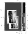
- the figure of a basic screen after image data was taken in.
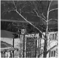
- the flowchart which shows the flow of a roughness removal process The figure which shows the image after the roughness removal which concerns on an Example.
- An image processing apparatus 1 shown in FIG. 1 is an embodiment of an image processing apparatus according to the present invention.
- the image processing apparatus 1 is a general-purpose personal computer.
- the image processing apparatus 1 is provided with an image processing program 2 as an embodiment of the image processing program according to the present invention from a computer-readable recording medium 60 such as a CD-ROM or a USB memory for storing the program. Installed.
- the image processing program 2 is application software for supporting image processing for moving images and still images.
- the image processing program 2 causes the image processing apparatus 1 to execute steps included in the operations described later.
- the image processing apparatus 1 includes a display 10, an input unit 20, a storage unit 30, and a control unit 40. These units 10 to 40 are connected to each other via a bus line, a cable 5 or the like and can communicate appropriately.
- the display 10 is composed of a liquid crystal display or the like, and displays a screen or the like described later to the user.
- the input unit 20 includes a mouse, a keyboard, a touch panel, and the like, and accepts an operation from the user for the image processing apparatus 1.
- the storage unit 30 is a non-volatile storage area configured from a hard disk, a flash memory, or the like.
- the control unit 40 includes a CPU, a ROM, a RAM, and the like.
- the image processing program 2 is stored in the storage unit 30.
- a software management area 50 is secured in the storage unit 30.
- the software management area 50 is an area used by the image processing program 2.
- an original image area 51 and a processed file area 52 are secured. The role of each of the areas 51 and 52 will be described later.
- the control unit 40 virtually operates as the display control unit 41 and the image processing unit 42 by reading out and executing the image processing program 2 stored in the storage unit 30. Further, the image processing unit 42 virtually operates as a smoothing unit 42a, a weighted average unit 42b, and a contrast enhancement unit 42c during execution of a roughness removing process described later.
- the display control unit 41 controls display of all elements such as screens, windows, buttons, and the like displayed on the display 10.
- the image processing unit 42 executes various types of image processing. Details of operations of the respective units 41, 42, 42a to 42c will be described later.
- control unit 40 detects that the user has performed a predetermined operation via the input unit 20, the control unit 40 activates the image processing program 2.
- image processing program 2 When the image processing program 2 is activated, a basic screen W1 (see FIG. 2) is displayed on the display 10.
- the basic screen W1 accepts an instruction for taking image data into the original image area 51 from the user.
- the image data taken into the original image area 51 is subject to later-described reproduction processing and image processing.
- the control unit 40 captures image data from the still image file or the moving image file into the original image area 51.
- a still image file is a data file in a still image format
- a moving image file is a data file in a moving image format.
- the control unit 40 When capturing image data from a still image file, the user operates the input unit 20 to specify one still image file or one folder.
- the control unit 40 causes the user to input the address path and file name in the storage unit 30 of the still image file.
- the control unit 40 causes the user to input the address path and folder name in the storage unit 30 of the folder.
- the control unit 40 stores the specified still image file or all the still image files in the specified folder as a still image file group in the original image area 51.
- the number of elements is not limited to a plurality, and may be one.
- the user when capturing image data from a moving image file, the user operates the input unit 20 to input the address path and file name in the storage unit 30 of one moving image file.
- the display control unit 41 detects that the user has specified a moving image file, the display control unit 41 displays a moving image capturing window (not shown) in an overlapping manner on the basic screen W1.
- the moving image capture window accepts selection of an arbitrary section from the user among all the sections of the timeline of the specified moving image file.
- the control unit 40 detects that the user has selected a specific section via the input unit 20, the control unit 40 generates a still image file group corresponding to the frame group included in the selected section on a one-to-one basis. Thereafter, the control unit 40 stores the still image file group in the original image area 51. Therefore, in the present embodiment, the image data to be subjected to playback processing and image processing to be described later is not a moving image file but a still image file.
- control unit 40 determines that the still image file group is taken along the timeline even if the still image file group captured in the original image area 51 is not derived from the moving image file but derived from the still image file. Are recognized as being arranged.
- the array is automatically determined from file attributes (file name, creation date, update date, etc.).
- the display control unit 41 displays the display window W2 (see FIG. 3) on the basic screen W1.
- the display windows W2 are created by the number of timelines of the still image file group taken into the original image area 51.
- one still image file (for example, a still image file corresponding to the first frame on the timeline) included in the still image file group captured in the original image area 51 is displayed in the display window W2. . Thereafter, as will be described later, the frame displayed in the display window W2 is switched in response to a user operation.
- a still image file for example, a still image file corresponding to the first frame on the timeline
- a window selection pull-down menu T1 As shown in FIG. 3, a window selection pull-down menu T1, a playback button T2, a frame advance button T3, a frame return button T4, and a timeline bar T5 are arranged on the basic screen W1.
- the window selection pull-down menu T1 accepts selection of which display window W2 is active from the user.
- a timeline corresponding to the active display window W2 is referred to as an active timeline
- a frame group belonging to the active timeline is referred to as an active frame group.
- a frame currently displayed in the active display window W2 is referred to as an active frame.
- the display control unit 41 can reproduce the active frame group as a moving image in the active display window W2.
- the playback button T2 receives a playback command from the user as a moving image of the active frame group.
- the display control unit 41 detects that the user has pressed the play button T2 via the input unit 20
- the frame included in the active frame group is sequentially framed along the timeline in the active display window W2. Display in the format. Note that the reproduction starts from the active frame at the time when the reproduction button T2 is pressed.
- the playback button T2 accepts a playback stop command from the user.
- the display control unit 41 detects that the user has pressed the playback button T2 via the input unit 20 during playback, the display control unit 41 fixes the display in the active display window W2 to the active frame at that time.
- the frame advance button T3 and the frame return button T4 each receive an instruction from the user to switch the active frame to the previous frame one by one along the active timeline.
- the timeline bar T5 is an object that schematically shows the active timeline.
- the timeline bar T5 is equally divided by the number of frames included in the active frame group in the direction in which the bar extends.
- the nth divided region from the left on the timeline bar T5 corresponds to the nth frame on the active timeline (n is a natural number).
- the display control unit 41 displays the divided area A1 corresponding to the selected frame group and the divided area A2 corresponding to the non-selected frame group in different display formats on the timeline bar T5. .
- the selected frame group is a frame group that belongs to the currently selected section on the active timeline.
- the non-selected frame group is a frame group that belongs to a section that is not currently selected on the active timeline.
- the timeline bar T5 accepts selection of an arbitrary section on the active timeline from the user.
- the section selected at this time may be a continuous section or a discontinuous section as shown in FIG.
- the user can select any number of arbitrary frames from the active frame group by manipulating the divided areas on the timeline bar T5 via the input unit 20.
- a plurality of divided areas can be selected at the same time.
- the display control unit 41 immediately switches the active frame to the frame corresponding to the most recently selected divided region every time the divided region on the timeline bar T5 is selected by the user.
- the image processing unit 42 recognizes the selected frame group as an image processing target to be described later.
- the image processing unit 42 can execute a plurality of image processing modules such as noise removal, roughness removal, sharpness, brightness / contrast / saturation adjustment, image resolution, addition of characters / arrows / mosaic, etc., on the selected frame group. is there.
- the image processing module is incorporated in the image processing program 2.
- the user can select any one of the image processing modules in any order and any number of times by operating the basic screen W1 via the input unit 20.
- the image processing module 42 executes the image processing module on the selected frame group at that time.
- executing the image processing module for the selected frame group means executing the image processing module for each frame included in the selected frame group.
- the image processing module As the image processing module is sequentially executed once, twice, three times,... With respect to the frame, the frame is sequentially sorted into the first order, the second order, the third order,. It will be processed.
- the 0th frame corresponds to the still image file stored in the original image area 51.
- the (m + 1) th frame corresponds to the still image file after the image processing module is executed once for the mth frame still image file (m is an integer of 0 or more).
- the image processing unit 42 sequentially generates still image files corresponding to the first and subsequent frames, and separately stores these still image files in the processed file area 52.
- FIG. 4 is a conceptual diagram showing how an image group belonging to one timeline is managed by the image processing program 2.
- the N axis on the horizontal axis indicates the order of frames on the timeline
- the M axis on the vertical axis indicates the order of processing.
- a square corresponding to the coordinates (n, m) in the NM space in FIG. 4 represents the image I (n, m).
- the image I (n, m) is an mth-order image of the nth frame on the timeline (n is a natural number, and m is an integer of 0 or more).
- the control unit 40 manages the value of the currently selected coordinate m as the parameter m s for each frame. Immediately after the still image file group is taken into the original image area 51, the coordinate m s has an initial value of 0. Thereafter, each time the image processing module is executed once, the coordinate m s of the frame is incremented by one. Further, the user can freely change the coordinate m s of an arbitrary frame by performing a predetermined operation via the input unit 20. Note that to execute the image processing module to the frame, it is to perform an image processing module to the m s next image of that frame. Therefore, changing the coordinate m s means changing the execution target of the image processing module. In addition, displaying a frame means displaying an image of the coordinate m s of the frame. Therefore, changing the coordinate m s also means changing the object displayed in the active display window W2.
- the roughness removal process is a process for removing the roughness included in the image.
- the “roughness” is typically a dot pattern of the screen that appears on an image captured by a camera on a monitor screen of a television or a personal computer.
- the roughness removal process it is possible to remove a pattern of fine features reflected in the image, that is, any texture generated in the image, regardless of the origin.
- the roughness removal according to the present embodiment can be considered as a kind of noise removal.
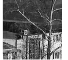
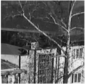
- the image shown in FIG. 5 is an example of a rough image, and is an image of an image that is actually shown on a monitor screen of a liquid crystal television.
- the roughness removal process proceeds according to the flowchart shown in FIG.
- the roughness removal process is started when it is detected that the user has performed a predetermined operation on the basic screen W1.
- step S1 parameters used in the subsequent processing are set. Specifically, in step S1, a parameter setting window (not shown) is displayed over the basic screen W1.
- the parameter setting window receives designation of a smoothing algorithm, a radius R, and a mixing ratio ⁇ , which are parameters used in the subsequent processing, from the user. In the present embodiment, any one of average, Gaussian, median, and Laplacian can be selected as the smoothing algorithm.
- Steps S2 to S6 are repeatedly executed for each frame included in the selected frame group.
- the image processing unit 42 selects one unprocessed frame from the selected frame group and sets it as the target frame F.
- the smoothing unit 42a smoothes the target frame F according to the smoothing algorithm specified in step S1.
- the smoothing in the present embodiment refers to the pixel value of each pixel included in the target frame F, the average value of the pixel values of the pixels in the vicinity region of the pixel (there may be a simple average value or a weighted average value). It is a process to replace with.
- the radius R specified in step S1 means the size of this neighboring area.
- the smoothing unit 42a performs smoothing by setting a 2R ⁇ 2R local region centered on each pixel as a neighboring region.
- an image generated by smoothing the target frame F is referred to as a smoothed image G.
- the smoothed image G is an image with less roughness compared to the target frame F.
- the radius R is set larger, the roughness disappears, but on the other hand, the outline (edge) is blurred.
- the roughness removing process according to the present embodiment can remove the roughness while leaving the outline, but the radius R is preferably set to be relatively small in order to sufficiently exhibit the effect.
- step S4 the weighted average unit 42b generates a difference image obtained by subtracting the target frame F from the smoothed image G.
- subtracting the image B from the image A means subtracting the pixel value of the pixel of the image B from the pixel value of the pixel of the image A for each pixel.
- the target frame F is a color image having three color components of RGB, and the pixel value for each color component is defined to take a value from 0 to 255. . In this case, the pixel value is subtracted for each color component.
- the pixel value of the pixels other than the roughness is approximately 0, the pixel value of the pixel having the bright roughness is a negative value, and the pixel value of the pixel having the dark roughness is A positive value.
- Bright roughness means that the pixel value is larger than the original pixel value when there is no roughness
- dark roughness means that the pixel value is smaller than the original pixel value when there is no roughness. is there.
- the dot pattern generated by close-up on the monitor screen appears bright, and the grid lines around the dot pattern appear dark.
- the pixel value is defined to take a value from 0 to 255, bright roughness information may be lost in the difference image.
- step S4 of the present embodiment after subtracting the target frame F from the smoothed image G, 128 is uniformly added to the pixel value of each pixel. Further, uniform addition is performed for each color component.
- a difference image H an image that has undergone such addition processing is referred to as a difference image H.
- the difference image H obtained in step S4 is an image in which the dark texture portion appears whitish, the bright texture appears dark, the contour portion appears whitish or dark, and the other portions appear gray.
- V H (j) V G (j) ⁇ V F (j) +128 (Formula 1)
- the weighted average unit 42b adds the target frame F and the difference image H with a weight using the value of the mixing ratio ⁇ set in step S1. Specifically, the weighted average unit 42b, for each pixel, a value obtained by multiplying the pixel value of the pixel of the difference image H by ⁇ and a value obtained by multiplying the pixel value of the pixel of the target frame F by (1 ⁇ ). Is added. This addition process is performed for each color component.
- the mixing ratio ⁇ a numerical value between 0 and 1 (0 and 1 are not included) can be set. Further, ⁇ is preferably set so that ⁇ > 0.5. In this case, in the weighted average image L, roughness and contour lines are amplified and added.
- the image obtained in step S5 is referred to as a weighted average image L.
- V L (j) ⁇ V H (j) + (1 ⁇ ) V F (j) (Formula 2)
- equation 1 substituting equation 1 into equation 2 yields equation 3 below.
- V L (j) (1-2 ⁇ ) V F (j) + ⁇ V G (j) + 128 ⁇ (Formula 3)
- the contrast enhancement unit 42c corrects the contrast of the weighted average image L so as to be enhanced.
- the weighted average image L after the contrast correction becomes a final corrected image Q by the roughness removal process.
- the corrected image Q is an image from which roughness is removed while maintaining the contour line as compared with the target frame F.
- the contrast is corrected according to the following expression 4.
- the V Q (j) (V L (j) ⁇ 128) * (1 / (1 ⁇ )) + 128 (Formula 4)
- the user can check the image with the roughness removed while maintaining the contour line by displaying the corrected image Q on the active display window W2.
- the image processing program 2 can handle image processing for a wide variety of moving images.
- the image processing program 2 can be used in a scene where an organization such as the police analyzes a surveillance video of a security camera for investigation of an incident.
- an investigation organization such as the police checks the video of a security camera near the scene of the incident.
- the video of the security cameras at various places is often recorded on a video tape, and it may be difficult to convert the video into a digital video so that it can be processed by a computer.
- the roughness removal process according to the above-described embodiment can be used to remove the roughness derived from the dot pattern on the monitor screen from the video shot through the monitor screen.
- the above roughness removal process functions particularly effectively for an image in which a component having a higher spatial frequency than the roughness to be removed is not included in the original pattern (a pattern having no roughness).
- the roughness removing process according to the present embodiment is particularly effective for removing a dot pattern generated by photographing the monitor screen.
- the method for generating the weighted average image L is not limited to that described above.
- the difference image H is generated by subtracting the target frame F from the smoothed image G.
- the reverse difference is generated.
- An image may be obtained.
- the weighted average unit 42b can obtain the difference image H by inverting the gradation of the inverse difference image. Subsequent processing can be performed in the same manner as in the above embodiment.
- the weighted average image L may be generated directly from the target frame F and the smoothed image G on the basis of the above formula 3, instead of stepwise through the processing of steps S4 and S5.
- step S6 may be omitted.
- the final corrected image by the roughness removal process is the weighted average image L.
- the contrast of the weighted average image L does not decrease when uniform addition processing of a predetermined value for each pixel value is not performed in step S4. In this case, of course, the contrast enhancement process in step S6 is unnecessary.
Abstract
Description
1)前記対象画像を平滑化した平滑化画像を生成するステップ。
2)前記対象画像と、前記平滑化画像から前記対象画像を減算した差分画像とを加重平均した加重平均画像を生成するステップ。
ここでは、第1観点と同様の効果を奏することができる。
1)前記ざらつきが残存するように前記対象画像を平滑化した平滑化画像を生成するステップ。
2)前記対象画像と、前記平滑化画像から前記対象画像を減算した差分画像とを加重平均した加重平均画像を生成するステップ。
ここでは、第1観点と同様の効果を奏することができる。
図1に示す画像処理装置1は、本発明に係る画像処理装置の一実施形態である。画像処理装置1は、汎用のパーソナルコンピュータである。画像処理装置1には、本発明に係る画像処理プログラムの一実施形態である画像処理プログラム2が、これを格納するCD-ROM、USBメモリ等のコンピュータが読み取り可能な記録媒体60等から提供され、インストールされている。画像処理プログラム2は、動画及び静止画に対する画像処理を支援するためのアプリケーションソフトウェアである。画像処理プログラム2は、画像処理装置1に後述する動作に含まれるステップを実行させる。
制御部40は、ユーザが入力部20を介して所定の操作を行ったことを検出すると、画像処理プログラム2を起動する。画像処理プログラム2が起動されると、基本画面W1(図2参照)がディスプレイ10上に表示される。
基本画面W1は、オリジナル画像領域51への画像データの取込みの命令をユーザから受け付ける。オリジナル画像領域51へ取り込まれた画像データは、後述する再生処理及び画像処理の対象になる。制御部40は、静止画ファイル又は動画ファイルから、オリジナル画像領域51へ画像データを取り込む。なお、本明細書において、静止画ファイルとは、静止画形式のデータファイルであり、動画ファイルとは、動画形式のデータファイルである。
オリジナル画像領域51へ静止画ファイル群が取り込まれると、表示制御部41は、基本画面W1上に表示ウィンドウW2(図3参照)を重ねて表示させる。表示ウィンドウW2は、オリジナル画像領域51へ取り込まれた静止画ファイル群のタイムラインの数だけ作成される。
画像処理部42は、選択フレーム群に対し、ノイズ除去、ざらつき除去、シャープネス、明るさ/コントラスト/彩度調整、画像解像度、文字/矢印/モザイクの付加などの複数の画像処理モジュールを実行可能である。画像処理モジュールは、画像処理プログラム2に組み込まれている。
以下、画像処理プログラム2に実装されている画像処理の1つである、ざらつき除去処理について説明する。ざらつき除去処理とは、画像に含まれるざらつきを除去する処理である。ここでいう「ざらつき」とは、典型的には、テレビやパソコン等のモニター画面をカメラで撮影した画像に写る、当該画面のドットパターンのことである。しかしながら、ざらつき除去処理では、発生の由来に関わらず、画像内に写り込んでいる細かな特徴のパターン、すなわち、画像に生じている任意のテクスチャの除去が可能である。この意味で、本実施形態に係るざらつき除去は、ノイズ除去の一種であると考えることもできる。なお、図5に示す画像は、ざらつきを有する画像の一例であり、実際に液晶テレビのモニター画面に写る画像を撮影したものである。
ステップS1で指定される半径Rは、この近傍領域のサイズを意味する。平滑化部42aは、各画素を中心とする2R×2Rの局所領域を近傍領域として設定し、平滑化を行う。以下、対象フレームFの平滑化により生成される画像を、平滑化画像Gと呼ぶ。
VH(j)=VG(j)-VF(j)+128 (式1)
VL(j)=αVH(j)+(1-α)VF(j) (式2)
なお、式2に式1を代入すると、以下の式3となる。
VL(j)=(1-2α)VF(j)+αVG(j)+128α (式3)
VQ(j)=(VL(j)-128)*(1/(1-α))+128 (式4)
画像処理プログラム2は、多種多様な動画に対する画像処理を取り扱うことができ、例えば、警察等の機関が事件の捜査のために防犯カメラの監視映像を解析する場面でも利用され得る。具体的には、警察等の捜査機関は、事件現場の近隣の防犯カメラの映像を確認する。このとき、各所の防犯カメラの映像は、ビデオテープで録画されていることが多く、これをコンピュータでの画像処理が可能なようにデジタル映像に変換することが困難なことがある。また、防犯カメラの所有者の下で監視映像を閲覧させてもらう許可を得ることができたとしても、その提出までを常に要求できる訳ではない。従って、現実には、現場のモニター画面に写る画像をデジタルカメラ等で撮影し、これを持ち帰ることがしばしば行われている。上記実施形態に係るざらつき除去処理は、このようなモニター画面越しに撮影された映像から、モニター画面のドットパターンに由来するざらつきを除去するのに利用することができる。
以上、本発明の一実施形態について説明したが、本発明は上記実施形態に限定されるものではなく、その趣旨を逸脱しない限りにおいて、種々の変更が可能である。例えば、以下の変更が可能である。
加重平均画像Lを生成する方法は、上述したものに限られない。例えば、上記実施形態におけるステップS4では、平滑化画像Gから対象フレームFを減算することにより差分画像Hが生成されたが、逆に、対象フレームFから平滑化画像Gを減算することにより逆差分画像を得てもよい。この場合、加重平均部42bは、当該逆差分画像の階調を反転させることにより、差分画像Hを得ることができる。以後の処理は、上記実施形態と同様に行うことができる。
上記実施形態において、ステップS6を省略してもよい。この場合、ざらつき除去処理による最終的な補正画像は、加重平均画像Lとなる。なお、ユーザは、加重平均画像Lのコントラストが低いと感じ、不都合を感じた場合にのみ、別途、コントラスト調整の画像処理を行って、手動で補正画像Qを得ればよい。また、そもそもステップS4において、各画素値に対する所定値の一律の加算処理が行われていない場合には、加重平均画像Lのコントラストが低下することはないと言える。この場合には、勿論、ステップS6におけるコントラストの強調処理は不要である。
以下、本発明の実施例について説明する。ただし、本発明は、以下の実施例に限定されない。本実施例では、図5に示す対象画像に対し、半径R=1で上記実施形態に係るステップS3~S6を実行したところ、図7に示す画像(補正画像Q)が得られた。一方、図5に示す対象画像に対し、半径R=3で上記実施形態に係るステップS3(平滑化処理)のみを行ったところ、図8に示す画像が得られた。
2 画像処理プログラム
42a 平滑化部
42b 加重平均部
42c コントラスト強調部
Claims (6)
- 対象画像に含まれるざらつきを除去する画像処理装置であって、
前記対象画像を平滑化した平滑化画像を生成する平滑化部と、
前記対象画像と、前記平滑化画像から前記対象画像を減算した差分画像とを加重平均した加重平均画像を生成する加重平均部と
を備える、
画像処理装置。 - 前記加重平均画像のコントラストを強調するコントラスト強調部
をさらに備える、
請求項1に記載の画像処理装置。 - 前記加重平均部は、前記平滑化画像から前記対象画像を減算した差分画像を生成した後、前記対象画像と前記差分画像とを加重平均することにより、前記加重平均画像を生成する、
請求項1又は2に記載の画像処理装置。 - 前記加重平均部は、前記対象画像から前記平滑化画像を減算した逆差分画像を生成した後、前記逆差分画像の階調を反転することにより、前記差分画像を生成する、
請求項2に記載の画像処理装置。 - 対象画像に含まれるざらつきを除去する画像処理プログラムであって、
前記対象画像を平滑化した平滑化画像を生成するステップと、
前記対象画像と、前記平滑化画像から前記対象画像を減算した差分画像とを加重平均した加重平均画像を生成するステップと
をコンピュータに実行させる、
画像処理プログラム。 - 対象画像に含まれるざらつきを除去する画像処理方法であって、
前記ざらつきが残存するように前記対象画像を平滑化した平滑化画像を生成するステップと、
前記対象画像と、前記平滑化画像から前記対象画像を減算した差分画像とを加重平均した加重平均画像を生成するステップと
を備える、
画像処理方法。
Priority Applications (4)
| Application Number | Priority Date | Filing Date | Title |
|---|---|---|---|
| US15/128,290 US10311550B2 (en) | 2014-03-27 | 2015-01-20 | Image processing device for eliminating graininess of image |
| JP2016510074A JP6520920B2 (ja) | 2014-03-27 | 2015-01-20 | 画像処理装置 |
| CN201580008441.9A CN105993032A (zh) | 2014-03-27 | 2015-01-20 | 图像处理装置 |
| EP15768884.7A EP3125191A4 (en) | 2014-03-27 | 2015-01-20 | Image processing device |
Applications Claiming Priority (2)
| Application Number | Priority Date | Filing Date | Title |
|---|---|---|---|
| JP2014-066864 | 2014-03-27 | ||
| JP2014066864 | 2014-03-27 |
Publications (1)
| Publication Number | Publication Date |
|---|---|
| WO2015146240A1 true WO2015146240A1 (ja) | 2015-10-01 |
Family
ID=54194782
Family Applications (1)
| Application Number | Title | Priority Date | Filing Date |
|---|---|---|---|
| PCT/JP2015/051362 WO2015146240A1 (ja) | 2014-03-27 | 2015-01-20 | 画像処理装置 |
Country Status (5)
| Country | Link |
|---|---|
| US (1) | US10311550B2 (ja) |
| EP (1) | EP3125191A4 (ja) |
| JP (1) | JP6520920B2 (ja) |
| CN (1) | CN105993032A (ja) |
| WO (1) | WO2015146240A1 (ja) |
Cited By (1)
| Publication number | Priority date | Publication date | Assignee | Title |
|---|---|---|---|---|
| KR20200079922A (ko) * | 2018-12-26 | 2020-07-06 | 주식회사 실리콘웍스 | 영상 처리 장치 및 그 방법 |
Families Citing this family (2)
| Publication number | Priority date | Publication date | Assignee | Title |
|---|---|---|---|---|
| US20150088921A1 (en) | 2013-09-20 | 2015-03-26 | Ebay Inc. | Search guidance |
| US11222064B2 (en) * | 2015-12-31 | 2022-01-11 | Ebay Inc. | Generating structured queries from images |
Citations (3)
| Publication number | Priority date | Publication date | Assignee | Title |
|---|---|---|---|---|
| JP2009267671A (ja) * | 2008-04-24 | 2009-11-12 | Nec Electronics Corp | 画像処理装置 |
| WO2011055772A1 (ja) * | 2009-11-05 | 2011-05-12 | 日本電気株式会社 | 画像目標識別装置、画像目標識別方法、画像目標識別プログラム |
| JP2011133683A (ja) * | 2009-12-24 | 2011-07-07 | Samsung Electronics Co Ltd | 画像処理装置、画像処理方法、プログラム、および表示装置 |
Family Cites Families (14)
| Publication number | Priority date | Publication date | Assignee | Title |
|---|---|---|---|---|
| JPS63244973A (ja) * | 1987-03-30 | 1988-10-12 | Toshiba Corp | 画像読取装置 |
| US5774599A (en) * | 1995-03-14 | 1998-06-30 | Eastman Kodak Company | Method for precompensation of digital images for enhanced presentation on digital displays with limited capabilities |
| US6055340A (en) * | 1997-02-28 | 2000-04-25 | Fuji Photo Film Co., Ltd. | Method and apparatus for processing digital images to suppress their noise and enhancing their sharpness |
| JPH1127533A (ja) * | 1997-07-07 | 1999-01-29 | Dainippon Screen Mfg Co Ltd | 輪郭強調方法及びその装置 |
| US7231072B2 (en) * | 2002-02-27 | 2007-06-12 | Konica Corporation | Image processing method and image converting apparatus |
| US7469056B2 (en) * | 2002-05-14 | 2008-12-23 | Ge Healthcare Niagara Inc. | System and methods for rapid and automated screening of cells |
| JP4413504B2 (ja) | 2003-02-13 | 2010-02-10 | 株式会社東芝 | 医用画像処理装置、医用画像処理方法および医用画像処理プログラム |
| JP4894595B2 (ja) * | 2007-04-13 | 2012-03-14 | ソニー株式会社 | 画像処理装置および方法、並びに、プログラム |
| JP4314305B1 (ja) * | 2008-02-04 | 2009-08-12 | シャープ株式会社 | 鮮鋭化画像処理装置、方法、及びソフトウェア |
| JP5223702B2 (ja) | 2008-07-29 | 2013-06-26 | 株式会社リコー | 画像処理装置、ノイズ低減方法、プログラム、記憶媒体 |
| JP5230456B2 (ja) * | 2009-01-09 | 2013-07-10 | キヤノン株式会社 | 画像処理装置および画像処理方法 |
| JP5398365B2 (ja) * | 2009-06-09 | 2014-01-29 | キヤノン株式会社 | 画像処理装置、画像処理方法 |
| US8340388B2 (en) * | 2009-11-03 | 2012-12-25 | Icad, Inc. | Systems, computer-readable media, methods, and medical imaging apparatus for the automated detection of suspicious regions of interest in noise normalized X-ray medical imagery |
| JP5368392B2 (ja) * | 2010-07-23 | 2013-12-18 | 信越化学工業株式会社 | 電子線用レジスト膜及び有機導電性膜が積層された被加工基板、該被加工基板の製造方法、及びレジストパターンの形成方法 |
-
2015
- 2015-01-20 WO PCT/JP2015/051362 patent/WO2015146240A1/ja active Application Filing
- 2015-01-20 EP EP15768884.7A patent/EP3125191A4/en not_active Withdrawn
- 2015-01-20 CN CN201580008441.9A patent/CN105993032A/zh active Pending
- 2015-01-20 JP JP2016510074A patent/JP6520920B2/ja active Active
- 2015-01-20 US US15/128,290 patent/US10311550B2/en active Active
Patent Citations (3)
| Publication number | Priority date | Publication date | Assignee | Title |
|---|---|---|---|---|
| JP2009267671A (ja) * | 2008-04-24 | 2009-11-12 | Nec Electronics Corp | 画像処理装置 |
| WO2011055772A1 (ja) * | 2009-11-05 | 2011-05-12 | 日本電気株式会社 | 画像目標識別装置、画像目標識別方法、画像目標識別プログラム |
| JP2011133683A (ja) * | 2009-12-24 | 2011-07-07 | Samsung Electronics Co Ltd | 画像処理装置、画像処理方法、プログラム、および表示装置 |
Non-Patent Citations (1)
| Title |
|---|
| See also references of EP3125191A4 * |
Cited By (4)
| Publication number | Priority date | Publication date | Assignee | Title |
|---|---|---|---|---|
| KR20200079922A (ko) * | 2018-12-26 | 2020-07-06 | 주식회사 실리콘웍스 | 영상 처리 장치 및 그 방법 |
| CN111383190A (zh) * | 2018-12-26 | 2020-07-07 | 硅工厂股份有限公司 | 图像处理设备和方法 |
| KR102575126B1 (ko) * | 2018-12-26 | 2023-09-05 | 주식회사 엘엑스세미콘 | 영상 처리 장치 및 그 방법 |
| CN111383190B (zh) * | 2018-12-26 | 2024-02-20 | 硅工厂股份有限公司 | 图像处理设备和方法 |
Also Published As
| Publication number | Publication date |
|---|---|
| JPWO2015146240A1 (ja) | 2017-04-13 |
| EP3125191A4 (en) | 2017-08-16 |
| JP6520920B2 (ja) | 2019-05-29 |
| US10311550B2 (en) | 2019-06-04 |
| CN105993032A (zh) | 2016-10-05 |
| US20170193636A1 (en) | 2017-07-06 |
| EP3125191A1 (en) | 2017-02-01 |
Similar Documents
| Publication | Publication Date | Title |
|---|---|---|
| US9262684B2 (en) | Methods of image fusion for image stabilization | |
| US7983511B1 (en) | Methods and apparatus for noise reduction in digital images | |
| JP2009093323A (ja) | 画像処理装置およびプログラム | |
| JP6101896B2 (ja) | 画像処理プログラムおよび画像処理装置 | |
| JP6904842B2 (ja) | 画像処理装置、画像処理方法 | |
| WO2015146240A1 (ja) | 画像処理装置 | |
| JP6171371B2 (ja) | 画像処理プログラム、画像処理装置および画像処理方法 | |
| CN112819699A (zh) | 视频处理方法、装置及电子设备 | |
| JP5751184B2 (ja) | 画像処理プログラム、画像処理装置および画像処理方法 | |
| JP6541501B2 (ja) | 画像処理装置、撮像装置、及び画像処理方法 | |
| US9361674B2 (en) | Image processing apparatus, image processing method, and storage medium | |
| JP5455728B2 (ja) | 撮像装置、画像処理装置、及び画像処理方法 | |
| US8837866B2 (en) | Image processing apparatus and method for controlling image processing apparatus | |
| JP2009027223A (ja) | 画像表示装置、画像表示方法、およびプログラム | |
| JP5832095B2 (ja) | 画像処理装置、画像処理方法、及びプログラム | |
| KR101612437B1 (ko) | 촬영 영상 처리 장치 및 방법 | |
| EP2631871B1 (en) | Virtual image generation | |
| US9298319B2 (en) | Multi-touch recognition apparatus using filtering and a difference image and control method thereof | |
| JP2017021467A (ja) | 画像処理装置、その制御方法、および制御プログラム | |
| JP6806356B2 (ja) | 画像処理装置、撮像システム、画像処理方法及びコンピュータプログラム | |
| JP2009218651A (ja) | 画像処理装置及び監視カメラ | |
| JP5201058B2 (ja) | 輪郭強調処理プログラム、輪郭強調処理方法及び輪郭強調処理装置 | |
| US9129357B2 (en) | Image processing apparatus, method of image processing, and recording medium storing image processing program | |
| JP2010103934A (ja) | 画像処理装置,デジタルカメラ,および画像処理プログラム | |
| JP2018195189A (ja) | 画像処理装置、画像処理方法、及び、プログラム |
Legal Events
| Date | Code | Title | Description |
|---|---|---|---|
| 121 | Ep: the epo has been informed by wipo that ep was designated in this application |
Ref document number: 15768884 Country of ref document: EP Kind code of ref document: A1 |
|
| ENP | Entry into the national phase |
Ref document number: 2016510074 Country of ref document: JP Kind code of ref document: A |
|
| REEP | Request for entry into the european phase |
Ref document number: 2015768884 Country of ref document: EP |
|
| WWE | Wipo information: entry into national phase |
Ref document number: 2015768884 Country of ref document: EP |
|
| WWE | Wipo information: entry into national phase |
Ref document number: 15128290 Country of ref document: US |
|
| NENP | Non-entry into the national phase |
Ref country code: DE |