WO2015145806A1 - 蓄電デバイスの製造装置および蓄電デバイスの製造方法 - Google Patents
蓄電デバイスの製造装置および蓄電デバイスの製造方法 Download PDFInfo
- Publication number
- WO2015145806A1 WO2015145806A1 PCT/JP2014/072970 JP2014072970W WO2015145806A1 WO 2015145806 A1 WO2015145806 A1 WO 2015145806A1 JP 2014072970 W JP2014072970 W JP 2014072970W WO 2015145806 A1 WO2015145806 A1 WO 2015145806A1
- Authority
- WO
- WIPO (PCT)
- Prior art keywords
- positive electrode
- insulating material
- electrode material
- current collector
- collector foil
- Prior art date
- Legal status (The legal status is an assumption and is not a legal conclusion. Google has not performed a legal analysis and makes no representation as to the accuracy of the status listed.)
- Ceased
Links
Images




Classifications
-
- H—ELECTRICITY
- H01—ELECTRIC ELEMENTS
- H01M—PROCESSES OR MEANS, e.g. BATTERIES, FOR THE DIRECT CONVERSION OF CHEMICAL ENERGY INTO ELECTRICAL ENERGY
- H01M4/00—Electrodes
- H01M4/02—Electrodes composed of, or comprising, active material
- H01M4/04—Processes of manufacture in general
- H01M4/0402—Methods of deposition of the material
- H01M4/0404—Methods of deposition of the material by coating on electrode collectors
-
- H—ELECTRICITY
- H01—ELECTRIC ELEMENTS
- H01M—PROCESSES OR MEANS, e.g. BATTERIES, FOR THE DIRECT CONVERSION OF CHEMICAL ENERGY INTO ELECTRICAL ENERGY
- H01M10/00—Secondary cells; Manufacture thereof
- H01M10/04—Construction or manufacture in general
- H01M10/0404—Machines for assembling batteries
-
- H—ELECTRICITY
- H01—ELECTRIC ELEMENTS
- H01M—PROCESSES OR MEANS, e.g. BATTERIES, FOR THE DIRECT CONVERSION OF CHEMICAL ENERGY INTO ELECTRICAL ENERGY
- H01M10/00—Secondary cells; Manufacture thereof
- H01M10/05—Accumulators with non-aqueous electrolyte
- H01M10/058—Construction or manufacture
-
- H—ELECTRICITY
- H01—ELECTRIC ELEMENTS
- H01M—PROCESSES OR MEANS, e.g. BATTERIES, FOR THE DIRECT CONVERSION OF CHEMICAL ENERGY INTO ELECTRICAL ENERGY
- H01M4/00—Electrodes
- H01M4/02—Electrodes composed of, or comprising, active material
- H01M4/13—Electrodes for accumulators with non-aqueous electrolyte, e.g. for lithium-accumulators; Processes of manufacture thereof
-
- H—ELECTRICITY
- H01—ELECTRIC ELEMENTS
- H01M—PROCESSES OR MEANS, e.g. BATTERIES, FOR THE DIRECT CONVERSION OF CHEMICAL ENERGY INTO ELECTRICAL ENERGY
- H01M4/00—Electrodes
- H01M4/02—Electrodes composed of, or comprising, active material
- H01M4/13—Electrodes for accumulators with non-aqueous electrolyte, e.g. for lithium-accumulators; Processes of manufacture thereof
- H01M4/139—Processes of manufacture
-
- H—ELECTRICITY
- H01—ELECTRIC ELEMENTS
- H01M—PROCESSES OR MEANS, e.g. BATTERIES, FOR THE DIRECT CONVERSION OF CHEMICAL ENERGY INTO ELECTRICAL ENERGY
- H01M50/00—Constructional details or processes of manufacture of the non-active parts of electrochemical cells other than fuel cells, e.g. hybrid cells
- H01M50/40—Separators; Membranes; Diaphragms; Spacing elements inside cells
- H01M50/403—Manufacturing processes of separators, membranes or diaphragms
- H01M50/406—Moulding; Embossing; Cutting
-
- H—ELECTRICITY
- H01—ELECTRIC ELEMENTS
- H01M—PROCESSES OR MEANS, e.g. BATTERIES, FOR THE DIRECT CONVERSION OF CHEMICAL ENERGY INTO ELECTRICAL ENERGY
- H01M50/00—Constructional details or processes of manufacture of the non-active parts of electrochemical cells other than fuel cells, e.g. hybrid cells
- H01M50/40—Separators; Membranes; Diaphragms; Spacing elements inside cells
- H01M50/46—Separators, membranes or diaphragms characterised by their combination with electrodes
-
- H—ELECTRICITY
- H01—ELECTRIC ELEMENTS
- H01M—PROCESSES OR MEANS, e.g. BATTERIES, FOR THE DIRECT CONVERSION OF CHEMICAL ENERGY INTO ELECTRICAL ENERGY
- H01M10/00—Secondary cells; Manufacture thereof
- H01M10/05—Accumulators with non-aqueous electrolyte
- H01M10/052—Li-accumulators
-
- Y—GENERAL TAGGING OF NEW TECHNOLOGICAL DEVELOPMENTS; GENERAL TAGGING OF CROSS-SECTIONAL TECHNOLOGIES SPANNING OVER SEVERAL SECTIONS OF THE IPC; TECHNICAL SUBJECTS COVERED BY FORMER USPC CROSS-REFERENCE ART COLLECTIONS [XRACs] AND DIGESTS
- Y02—TECHNOLOGIES OR APPLICATIONS FOR MITIGATION OR ADAPTATION AGAINST CLIMATE CHANGE
- Y02E—REDUCTION OF GREENHOUSE GAS [GHG] EMISSIONS, RELATED TO ENERGY GENERATION, TRANSMISSION OR DISTRIBUTION
- Y02E60/00—Enabling technologies; Technologies with a potential or indirect contribution to GHG emissions mitigation
- Y02E60/10—Energy storage using batteries
-
- Y—GENERAL TAGGING OF NEW TECHNOLOGICAL DEVELOPMENTS; GENERAL TAGGING OF CROSS-SECTIONAL TECHNOLOGIES SPANNING OVER SEVERAL SECTIONS OF THE IPC; TECHNICAL SUBJECTS COVERED BY FORMER USPC CROSS-REFERENCE ART COLLECTIONS [XRACs] AND DIGESTS
- Y02—TECHNOLOGIES OR APPLICATIONS FOR MITIGATION OR ADAPTATION AGAINST CLIMATE CHANGE
- Y02P—CLIMATE CHANGE MITIGATION TECHNOLOGIES IN THE PRODUCTION OR PROCESSING OF GOODS
- Y02P70/00—Climate change mitigation technologies in the production process for final industrial or consumer products
- Y02P70/50—Manufacturing or production processes characterised by the final manufactured product
Definitions
- the present invention relates to a manufacturing apparatus and a manufacturing method for an electricity storage device, and can be suitably used for, for example, a step of applying an electrode material for an electricity storage device.
- Patent Document 1 JP-A-2003-054991
- This publication includes a positive electrode sheet delivery mechanism, a positive electrode material coating mechanism, a positive electrode forming heating mechanism, an electrolysis and insulating material coating mechanism, an electrolysis and insulator forming heating mechanism, and a negative electrode sheet.
- Secondary equipped with a state material delivery mechanism, a negative electrode material coating mechanism, a negative electrode formation heating mechanism, an electrolysis / insulation material coating mechanism, an electrolysis / insulator formation heating mechanism, and a winding mechanism A battery manufacturing apparatus is described.
- the winding mechanism is formed by laminating a positive electrode sheet material to which a positive electrode material and electrolysis and an insulating material are fixed, and a negative electrode sheet material to which a negative electrode material and an electrolysis and insulating material are fixed, to form a predetermined shape. It is a rotating mechanism.
- a positive or negative electrode material (also referred to as an electrode material or an electrode active material) is provided on both sides of a current collector foil (also referred to as a metal foil, an electrode plate, a base material, a substrate, or a sheet).
- a current collector foil also referred to as a metal foil, an electrode plate, a base material, a substrate, or a sheet.
- the thickness of the insulating material is, for example, about 5 ⁇ m to 40 ⁇ m
- the insulating material may be cut and the electrode material may be exposed.
- the side surfaces of the electrode material are inclined, and the thickness of the electrode material becomes non-uniform, making it impossible to form an electrode material having a desired shape. For these reasons, there is a problem that the production yield of the secondary battery is lowered.
- An apparatus for manufacturing an electricity storage device includes a plurality of slurry-like first surfaces spaced apart from each other in a second direction orthogonal to the first direction and the surface of the current collector foil on the surface of the current collector foil traveling in the first direction.
- a first application mechanism that applies one insulating material; and a second application mechanism that applies a slurry-like electrode material to a surface of a current collector foil sandwiched between first insulating materials adjacent in a second direction.
- a third application mechanism is provided for applying a slurry-like second insulating material on the upper surfaces of the first insulating material and the electrode material.
- a method for manufacturing an electricity storage device includes a plurality of slurry-like first surfaces separated from each other in a second direction orthogonal to the first direction and the surface of the current collector foil on the surface of the current collector foil traveling in the first direction.
- a step of applying an insulating material a step of applying a slurry-like electrode material to the surface of a current collector foil sandwiched between first insulating materials adjacent in the second direction, and an upper surface of the first insulating material and the electrode material. And applying a slurry-like second insulating material.
- the production yield of power storage devices such as lithium ion batteries can be improved.
- FIG. 1 is a schematic diagram of an apparatus for producing an electrode sheet for a lithium ion battery in Embodiment 1.
- FIG. It is sectional drawing of the electrode sheet of each application
- FIG. (A) is sectional drawing (sectional drawing of A1-A1 of FIG. 1) of the electrode sheet of a 1st insulating material (spacer material) application
- (B) is a cross-sectional view of the electrode sheet in the electrode material application step (cross-sectional view of B1-B1 in FIG. 1).
- C) is a cross-sectional view (cross-sectional view of C1-C1 in FIG.
- FIG. 3 is a process diagram summarizing a specific manufacturing process of the lithium ion battery in the first embodiment.
- 6 is a schematic diagram of a production apparatus for an electrode sheet of a lithium ion battery in Embodiment 2.
- FIG. It is principal part sectional drawing of the electrode sheet of each application
- FIG. (A) is sectional drawing (sectional drawing of A2-A2 of FIG.
- FIG. 5B is a cross-sectional view of the electrode sheet in the first insulating material (spacer material) application step (cross-sectional view taken along B2-B2 in FIG. 4).
- C is a cross-sectional view of the electrode sheet in the second insulating material (separator material) application step (cross-sectional view of C2-C2 in FIG. 4).
- D is a cross-sectional view of the electrode sheet in the drying step (cross-sectional view of D2-D2 in FIG. 4).
- 6 is a schematic diagram of a production apparatus for an electrode sheet of a lithium ion battery according to Embodiment 3.
- FIG. 3 is a schematic diagram of a production apparatus for an electrode sheet of a lithium ion battery according to Embodiment 3.
- FIG. (A) is sectional drawing (sectional drawing of A3-A3 of FIG. 6) of the electrode sheet of a 1st insulating material (spacer material) application
- FIG. 6B is a cross-sectional view of the electrode sheet in the first electrode material application step (cross-sectional view of B3-B3 in FIG. 6).
- (C) is a cross-sectional view of the electrode sheet in the second electrode material application step (C3-C3 cross-sectional view of FIG. 6).
- (D) is a cross-sectional view of the electrode sheet in the second insulating material (separator material) application step (cross-sectional view of D3-D3 in FIG. 6).
- (E) is a cross-sectional view of the electrode sheet in the drying process (cross-sectional view of E3-E3 in FIG. 6). It is process drawing which put together the specific manufacturing process of the lithium ion battery shown as a comparative example. It is the schematic of the manufacturing apparatus of the electrode sheet
- the constituent elements are not necessarily indispensable unless otherwise specified and apparently essential in principle. Needless to say.
- the positive electrode material and the negative electrode material are collectively referred to as “electrode material”, the film made of the positive electrode material after the drying process is called “positive electrode film”, and the film made of the negative electrode material after the drying process is called “negative electrode film”.
- the positive electrode film and the negative electrode film are collectively referred to as “electrode film”.
- the positive electrode material, the negative electrode material, and the insulating material before the drying step are substances having fluidity including a liquid such as a binder solution and an organic solvent.
- the current collector foil on which the positive electrode film is formed is “positive electrode sheet (also referred to as positive electrode plate)”, and the current collector foil on which the negative electrode film is formed is “negative electrode sheet (also referred to as negative electrode plate)”.
- the positive electrode sheet and the negative electrode sheet are collectively referred to as an “electrode sheet (also referred to as an electrode plate)”.
- the surface of the current collector foil refers to only the front surface, not the entire surface including the front surface and the back surface of the current collector foil.
- a direction in which the current collector foil travels is referred to as a “first direction”
- a direction orthogonal to the first direction on the surface of the current collector foil is referred to as a “second direction”.
- a lithium ion battery is exemplified as a secondary battery that is an electricity storage device, and a manufacturing apparatus and a manufacturing method thereof will be described, but the present invention is not limited to this.
- the lithium ion battery is a kind of non-aqueous electrolyte secondary battery, and is a secondary battery in which lithium ions in the electrolyte bear electric conduction.
- a lithium-containing composite oxide is used for the positive electrode, and a carbonaceous material is used for the negative electrode.
- the electrolyte for example, an organic solvent such as ethylene carbonate or a lithium salt such as lithium hexafluorophosphate (LiPF 6 ) is used.
- LiPF 6 lithium hexafluorophosphate
- a positive electrode sheet coated with a positive electrode material on the surface of a current collector foil eg, Al (aluminum) foil
- a negative electrode material applied on the surface of a current collector foil eg, Cu (copper) foil
- An electrode winding body is provided in which a negative electrode sheet and a separator such as a polymer film that prevents contact between the positive electrode film and the negative electrode film are wound. And in a lithium ion battery, while this electrode winding body is inserted in an armored can, electrolyte solution (the said electrolyte) is inject
- a positive electrode sheet in which a positive electrode material is coated on the surface of a current collector foil and a negative electrode sheet in which a negative electrode material is coated on the surface of a current collector foil are formed in a band shape, and the positive electrode formed in a band shape
- the sheet and the negative electrode sheet are wound in a cross-sectional spiral shape through a separator so that the positive electrode film on the positive electrode sheet and the negative electrode film on the negative electrode sheet are not in direct contact with each other to form an electrode winding body.
- FIG. 8 is a process diagram summarizing a specific manufacturing process of a lithium ion battery shown as a comparative example.
- the manufacturing process of the lithium ion battery includes a positive electrode sheet manufacturing process, a negative electrode sheet manufacturing process, a battery cell assembly process, and a battery module assembly process.
- a slurry-like positive electrode material is applied to the surface of a film-like current collector foil (positive electrode material application), and then the upper and side surfaces of the positive electrode material and the current collector foil to which no positive electrode material is applied
- a slurry-like insulating material to be a separator is applied to the surface of the substrate (application of separator material).
- drying after drying the entire coating film obtained by laminating the slurry-like positive electrode material and the slurry-like insulating material (drying), a laminated film of the positive electrode film made of the positive electrode material and the separator made of the insulating material is formed.
- the current collector foil is subjected to processing such as compression and cutting (processing) to produce a film-like positive electrode sheet having a positive electrode film and a separator.
- the procedure until the negative electrode sheet is manufactured is the same as in the positive electrode sheet manufacturing process.
- a separator is formed on the upper surface and side surfaces of the negative electrode material and on the surface of the current collector foil on which the negative electrode material is not applied.
- a slurry-like insulating material is applied (separator material application).
- a laminated film of the negative electrode film made of the negative electrode material and the separator made of the insulating material is formed.
- the current collector foil is subjected to processing such as compression and cutting (processing) to produce a film-like negative electrode sheet having a negative electrode film and a separator.
- a positive electrode having a size necessary for the battery cell is cut out from the film-like positive electrode sheet, and a negative electrode having a size necessary for the battery cell is cut out from the film-like negative electrode sheet.
- a group of positive and negative electrode pairs assembled together is assembled and welded (welding / assembly). Subsequently, the group of welded electrode pairs is placed in a battery can into which an electrolytic solution has been injected (injection), and then the battery can is completely sealed (sealing) to produce a battery cell.
- the produced battery cell is repeatedly charged / discharged (charge / discharge), and the performance and reliability of the battery cell are examined (for example, the capacity and voltage of the battery cell, and the current and current during charging or discharging the battery cell (Inspection of voltage etc.) (single cell inspection). Thereby, a battery cell is completed and a battery cell assembly process is complete
- a battery module is configured by combining a plurality of battery cells in series, and a battery system is configured by connecting a controller for charge / discharge control (module assembly).
- module assembly a controller for charge / discharge control
- an inspection regarding performance and reliability of the assembled battery module for example, inspection of capacity and voltage of the battery module, current and voltage at the time of charging or discharging the battery module, etc.
- FIG. 9 is a schematic view of an apparatus for manufacturing an electrode sheet of a lithium ion battery shown as a comparative example.
- surface of a positive electrode sheet is illustrated. Although omitted here, the manufacturing process of one side of the negative electrode sheet is the same.
- the current collector foil PEP is fed from the unwinding roll SL1, and the first roller RL1, the second roller RL2, the third roller RL3, the fourth roller RL4, the fifth roller RL5, and the sixth roller RL6. Is conveyed to the take-up roll SL2.
- a first slit die coater DC1 is installed facing the third roller RL3, and a second slit die coater DC2 is installed facing the fourth roller RL4.
- the slurry-like positive electrode material PAS supplied from the first slit die coater DC1 at a position facing the third roller RL3 is applied to the surface of the current collector foil PEP fed from the unwinding roll SL1.
- the positive electrode material PAS is stored in the tank TA1, and is supplied to the surface of the current collector foil PEP by the metering pump PU1.
- a slurry-like insulating material IF supplied from the second slit die coater DC2 at a position facing the fourth roller RL4 is applied.
- the insulating material IF is stored in the tank TA2, and is supplied to the surface of the current collector foil PEP coated with the positive electrode material PAS by the metering pump PU2. That is, the insulating material IF is applied to the upper surface and side surfaces of the positive electrode material PAS and the surface of the current collector foil PEP to which the positive electrode material PAS is not applied.
- the entire coating film obtained by laminating the positive electrode material PAS and the insulating material IF formed on the surface of the current collector foil PEP was dried, and the coating film was formed on the surface.
- the current collector foil PEP is wound around the winding roll SL2.
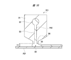
- FIG. 10 is a cross-sectional view schematically illustrating the state of application of the slurry-like positive electrode material PAS by the first slit die coater DC1. Although omitted here, the state of application of the slurry-like insulating material IF by the second slit die coater DC2 is also the same.
- the slurry-like positive electrode material PAS is supplied to the manifold D2 of the die D1 from the tank in which the slurry-like cathode material PAS is stored by a metering pump.
- the manifold D2 After the pressure distribution of the slurry-like positive electrode material PAS becomes uniform, the slurry-like positive electrode material PAS is supplied to and discharged from the slit portion D3 provided in the die D1.
- the discharged slurry-like positive electrode material PAS forms an electrode material reservoir D4 called a bead between the base D1 and the current collector foil PEP that travels relative to the base D1 while maintaining the first distance h1.
- the slurry-like positive electrode material PAS is pulled out as the current collector foil PEP travels to form a coating film made of the positive electrode material PAS.
- the coating film is continuously formed.
- the pressure for supplying the positive electrode material PAS to the manifold D2 is (pressure loss of the slit portion D3 + pressure loss of the downstream lip portion D6 of the base D1 + pressure of the downstream meniscus D5).
- the inventors of the present invention are studying to increase the capacity and miniaturization of lithium ion batteries, and as one means for that, are studying a thinner separator and a thicker electrode film (positive electrode film and negative electrode film). .
- the material IF cannot be uniformly applied, and the separator is cut off. Further, even if the insulating material IF can be uniformly applied to the upper surface of the electrode material, the insulating material IF can be uniformly applied to the side surfaces of the electrode material and the surface of the current collector foil PEP to which the electrode material is not applied. Can not. Furthermore, in order to form a thick electrode film, the electrode material must be applied thickly on the surface of the current collector foil PEP. However, when the electrode material is applied thickly, the side surface of the electrode material is inclined (current collector foil PEP).
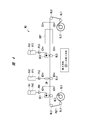
- FIG. 1 is a schematic diagram of an apparatus for manufacturing an electrode sheet for a lithium ion battery according to the first embodiment.
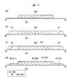
- FIG. 2 is a cross-sectional view of the electrode sheet in each coating step and drying step for explaining the method for producing the electrode sheet of the lithium ion battery in the first embodiment.
- 2A is a cross-sectional view of the electrode sheet in the first insulating material (spacer material) application step (cross-sectional view of A1-A1 in FIG. 1), and FIG.
- FIG. 2B is a cross-sectional view of the electrode sheet in the electrode material application step.
- FIG. 2C are cross-sectional views (cross-sectional view of C1-C1 in FIG. 1) of the electrode sheet in the second insulating material (separator material) application step.
- FIG. 2D is a cross-sectional view of the electrode sheet in the drying process (cross-sectional view of D1-D1 in FIG. 1).
- Embodiment 1 exemplifies a method of manufacturing a positive electrode film formed in two rows on the surface of the current collector foil along the first direction in which the current collector foil travels. Moreover, in this Embodiment 1, although the manufacturing method of the single side
- the current collector foil PEP is fed from the unwinding roll SL1, and the first roller RL1, the second roller RL2, the third roller RL3, the fourth roller RL4,
- the paper is conveyed to the take-up roll SL2 by the 5-roller RL5, the sixth roller RL6, and the seventh roller RL7.
- a dispenser DP is installed facing the third roller RL3, a first slit die coater DC1 is installed facing the fourth roller RL4, and a second slit die coater DC2 is installed facing the fifth roller RL5.
- First coating process First insulating material (spacer material) coating process
- the first insulating material IF1 is stored in the tank TA1, and is supplied to the surface of the current collector foil PEP by the metering pump PU1.
- the plurality of first insulating materials IF1 are arranged on the surface of the current collector foil PEP traveling in the first direction in the second direction orthogonal to the first direction and the surface of the current collector foil PEP. They are applied separately from each other. That is, the plurality of first insulating materials IF1 collects current in such a manner that a region in which the positive electrode material PAS is applied to the surface of the current collector foil PEP traveling in the first direction in the second application step is sandwiched in the second direction. It is applied to the surface of the foil PEP.
- the plurality of first insulating materials IF1 regulate the width in the second direction of the region of the positive electrode material PAS applied to the surface of the current collector foil PEP traveling in the first direction in the subsequent second application step.
- the plurality of first insulating materials IF1 are separated from each other in the second direction, and the current collector foil Three rows are applied to the surface of the PEP along the first direction.
- the thickness of the first insulating material IF1 is substantially the same as the thickness of the positive electrode material PAS applied to the surface of the current collector foil PEP in the subsequent second application step.
- the region to which the first insulating material IF1 is applied is a region that is cut after the positive electrode sheet is completed, the width in the second direction of the first insulating material IF1 is set to be small in order to reduce the material cost.
- the width in the second direction of the first insulating material IF1 is about 5 mm to 15 mm.
- Second application process electrode material application process
- the slurry-like positive electrode material PAS supplied from the first slit die coater DC1 at a position facing the fourth roller RL4 is applied to the surface of the current collector foil PEP fed from the unwinding roll SL1.
- the positive electrode material PAS is stored in the tank TA2, and is supplied to the surface of the current collector foil PEP by the metering pump PU2.
- the plurality of positive electrode materials PAS are applied to the surface of the current collector foil PEP traveling in the first direction and to the surface of the current collector foil PEP in the previous first application step. 1 It apply
- the plurality of positive electrode materials PAS are separated by the first insulating material IF1 in the second direction. Two rows are applied along the first direction on the surface of the current collector foil PEP so as to be separated from each other.
- the thickness of the positive electrode material PAS is substantially the same as the thickness of the first insulating material IF1. Although it is desirable that the thickness of the positive electrode material PAS and the thickness of the first insulating material IF1 are the same, in order to prevent the positive electrode material PAS from being applied to the upper surface of the first insulating material IF1, the upper surface of the positive electrode material PAS is 1
- the positive electrode material PAS is applied so as to be lower by about 0 ⁇ m to 10 ⁇ m than the upper surface of the insulating material IF1.
- the thickness of the positive electrode material PAS can be adjusted, for example, by adjusting the height of the base D1 of the first slit die coater DC1 (see FIG. 10) and the feed amount of the positive electrode material PAS.
- the positive electrode material PAS When the first insulating material IF1 is not applied, when the positive electrode material PAS is applied thickly, the side surface of the positive electrode material PAS is inclined, and a depression is formed on the upper surface of the positive electrode material PAS, so that the shape of the positive electrode material PAS is not stable. There is a problem. However, in the first embodiment, since the region where the positive electrode material PAS is applied is defined in advance by the first insulating material IF1, the positive electrode material can be applied even if the positive electrode material PAS is applied thickly (eg, about 100 ⁇ m to 400 ⁇ m). Since the side surface of the PAS is not inclined, the shape of the positive electrode material PAS is stabilized.
- Second insulating material (separator material) coating process Next, a slurry-like second insulating material IF2 supplied from the second slit die coater DC2 at a position facing the fifth roller RL5 is applied.
- the second insulating material IF2 is stored in the tank TA3, and is supplied to the upper surfaces of the first insulating material IF1 and the positive electrode material PAS by the metering pump PU3.
- the second insulating material IF2 is applied to the upper surfaces of the first insulating material IF1 and the positive electrode material PAS along the first direction in which the current collector foil PEP travels.
- the thickness of the second insulating material IF2 is, for example, about 5 ⁇ m to 40 ⁇ m.
- the thickness of the second insulating material IF2 can be adjusted, for example, by adjusting the height of the base D1 of the second slit die coater DC2 (see FIG. 10) and feeding the second insulating material IF2.
- the second insulating material IF2 is applied to the upper surfaces of the first insulating material IF1 and the positive electrode material PAS, which are substantially flat surfaces, for example, the side surfaces of the first insulating material IF1 and the positive electrode material PAS, and the first insulating material IF1 and It is not applied to the surface of the current collector foil PEP to which the positive electrode material PAS is not applied.
- the second insulating material IF2 can be uniformly applied, so the film of the second insulating material IF2 Cutting can be prevented.
- the thickness of the positive electrode material PAS and the thickness of the first insulating material IF1 were substantially the same before drying, but after drying, the thickness of the spacer SP made of the first insulating material IF1.
- the thickness is smaller than the thickness of the positive electrode film PE made of the positive electrode material PAS. This is due to the difference between the amount of solid matter (eg, positive electrode active material and conductive additive) contained in the positive electrode material PAS and the amount of solid matter contained in the first insulating material IF1. That is, the amount of the solid matter contained in the positive electrode material PAS is relatively large, and the amount of the solid matter contained in the first insulating material IF1 is controlled to be relatively small. It is made thinner than the thickness of the positive electrode film PE.
- the positive electrode film PE and the spacer SP were applied to the upper surfaces of these after drying.
- the laminated film with the separator SE made of the second insulating material IF2 is cut, the laminated film is compressed (roll press). During the compression, it is important to apply a load to the positive electrode film PE. Therefore, if the spacer SP is thicker than the positive electrode film PE, the load is not applied to the positive electrode film PE. Therefore, it is necessary to make the thickness of the spacer SP thinner than the thickness of the positive electrode film PE.
- the method for manufacturing the positive electrode film PE formed in two rows on the surface of the current collector foil PEP along the first direction in which the current collector foil PEP travels is exemplified, but the present invention is not limited thereto. It is not something.
- the positive electrode film PE may be one row or three or more rows, and the same effect can be obtained.
- FIG. 3 is a process diagram summarizing a specific manufacturing process of the lithium ion battery in the first embodiment.
- the manufacturing process of the lithium ion battery is the same as the manufacturing process of the lithium ion battery shown in FIG. 8, the positive electrode sheet manufacturing process, the negative electrode sheet manufacturing process, the battery cell assembling process, and the battery. Module assembly process.
- the first insulating material is produced by mixing and preparing various materials as raw materials.
- a slurry-like positive electrode material is applied between the first insulating materials applied separately in the second direction (positive electrode material application).
- the positive electrode material is produced by mixing and preparing various materials as raw materials.
- a slurry-like second insulating material serving as a separator is applied to the top surfaces of the first insulating material and the positive electrode material formed on the surface of the film-like current collector foil (separator material application).
- the second insulating material is produced by mixing and preparing various materials as raw materials.
- the film-form current collector foil has a film-like shape in which the positive electrode film made of the positive electrode material and the spacer made of the first insulating material and the separator made of the second insulating material formed on the upper surface thereof are laminated.
- the positive electrode sheet is manufactured.
- the negative electrode sheet manufacturing process various materials used as raw materials are different from those in the positive electrode sheet manufacturing process, but the procedure until the negative electrode sheet is manufactured is the same as in the positive electrode sheet manufacturing process.
- a plurality of slurry-like first insulating materials serving as spacers are applied to the surface of a film-like current collecting foil in a second direction perpendicular to the first direction in which the current collecting foil runs (spacer). Material application).
- the first insulating material is produced by mixing and preparing various materials as raw materials.
- a slurry-like negative electrode material is applied between the first insulating materials applied in the second direction so as to be separated from each other on the surface of the film-like current collecting foil (negative electrode material application).
- the negative electrode material is produced by mixing and preparing various materials as raw materials.
- a slurry-like second insulating material serving as a separator is applied to the upper surfaces of the first insulating material and the negative electrode material formed on the surface of the film-like current collecting foil (separator material application).
- the second insulating material is produced by mixing and preparing various materials as raw materials.
- a positive electrode having a size necessary for the battery cell is cut out from the film-like positive electrode sheet, and a negative electrode having a size necessary for the battery cell is cut out from the film-like negative electrode sheet.
- each material of lithium ion battery for example, a lithium-containing composite oxide having a spinel structure containing lithium cobaltate or Mn (manganese) can be used.
- a composite oxide containing Ni (nickel), Co (cobalt), and Mn (manganese), or an olivine type compound represented by olivine type iron phosphate can be used.
- the material used for the positive electrode active material is not limited to these.
- a lithium-containing composite oxide having a spinel structure containing Mn (manganese) is excellent in thermal stability, a lithium ion battery with high safety can be formed by forming a positive electrode sheet containing this.
- the positive electrode active material only a lithium-containing composite oxide having a spinel structure containing Mn (manganese) may be used, but other positive electrode active materials may be used in combination. Examples of such other positive electrode active materials include olivine type represented by Li 1 + x MO 2 ( ⁇ 0.1 ⁇ x ⁇ 0.1, M: Co, Ni, Mn, Al, Mg, Zr, Ti, etc.), for example. Compound etc. are mentioned.
- lithium-containing transition metal oxide having a layer structure examples include LiCoO 2 or LiNi 1-x Co xy Al y O 2 (0.1 ⁇ x ⁇ 0.3, 0.01 ⁇ y ⁇ 0). .2) can be used.
- the lithium-containing transition metal oxide having a layered structure includes an oxide containing at least Ni (nickel), Co (cobalt), and Mn (manganese) (LiMn 1/3 Ni 1/3 Co 1/3 O 2 , LiMn 5/12 Ni 5/12 Co 1/6 O 2 , LiNi 3/5 Mn 1/5 Co 1/5 O 2, etc.) can be used.
- a graphite material such as natural graphite (flaky graphite), artificial graphite, or expanded graphite can be used.
- an easily graphitizable carbonaceous material such as coke obtained by firing pitch can be used.
- a non-graphitizable carbonaceous material such as amorphous carbon obtained by low-temperature firing of furfuryl alcohol resin (PFA), polyparaphenylene (PPP), phenol resin, or the like may be used as the negative electrode active material.
- PFA furfuryl alcohol resin
- PPP polyparaphenylene
- phenol resin phenol resin
- Li (lithium) or a lithium-containing compound can also be used as the negative electrode active material.
- lithium-containing compound examples include a lithium alloy such as Li—Al or an alloy containing an element that can be alloyed with Li (lithium) and Si (silicon) or Sn (tin). Furthermore, an oxide-based material such as Sn oxide or Si oxide can also be used.
- a lithium alloy such as Li—Al or an alloy containing an element that can be alloyed with Li (lithium) and Si (silicon) or Sn (tin).
- an oxide-based material such as Sn oxide or Si oxide can also be used.
- the conductive auxiliary agent used in the first embodiment is used as an electronic conductive auxiliary agent to be contained in the positive electrode film.
- a carbon material such as carbon black, acetylene black, ketjen black, graphite, carbon fiber, or carbon nanotube is preferable.
- acetylene black or ketjen black is particularly preferable from the viewpoint of the amount of addition and conductivity and the manufacturability of the coating positive electrode mixture slurry.
- the conductive auxiliary agent can be contained in the negative electrode film, and may be preferable.
- the binder used in the first embodiment preferably also contains a binder for binding the active material and the conductive additive.
- a binder for example, a polyvinylidene fluoride-based polymer (a polymer of a fluorine-containing monomer group containing 80% by mass or more of vinylidene fluoride as a main component monomer) or a rubber-based polymer is preferably used. Two or more of the above polymers may be used in combination.
- the binder is preferably provided in the form of a solution dissolved in a solvent.
- Examples of the fluorine-containing monomer group for synthesizing the polyvinylidene fluoride-based polymer include vinylidene fluoride, or a mixture of vinylidene fluoride and another monomer, and a monomer mixture containing 80% by mass or more of vinylidene fluoride. Can be mentioned. Examples of other monomers include vinyl fluoride, trifluoroethylene, trifluorochloroethylene, tetrafluoroethylene, hexafluoropropylene, and fluoroalkyl vinyl ether.
- Examples of the rubber-based polymer include styrene butadiene rubber (SBR), ethylene propylene diene rubber, and fluorine rubber.
- SBR styrene butadiene rubber
- ethylene propylene diene rubber examples include fluorine rubber.
- Content of the binder in an electrode film is 0.1 mass% or more on the basis of the electrode film after drying, More preferably, it is 0.3 mass% or more, 10 mass% or less, Furthermore, it is 5 mass% or less. More desirable. If the binder content is too small, not only is the solidification in the drying process insufficient, but the mechanical strength of the electrode film after drying is insufficient, and the electrode film may peel from the current collector foil. Moreover, when there is too much content of a binder, there exists a possibility that the amount of active materials in an electrode film may reduce and battery capacity may become low.
- an inorganic oxide such as Al 2 O 3 (alumina) or SiO 2 (silica) can be used.
- a slurry in which fine particles of polypropylene or polyethylene are confused may be used, and by using this, shutdown property can be provided.
- a resin is used as a binder.
- the binder used for the electrode film is preferably used as the binder.
- the current collector foil used in the first embodiment is not limited to a sheet-like foil.
- the substrate for example, pure metal or alloy conductive material such as Al (aluminum), Cu (copper), stainless steel or Ti (titanium) is used, and the shape thereof is a net, punched metal, foam metal or plate.
- a foil processed into a shape is used.
- the thickness of the current collector foil for example, 5 ⁇ m to 30 ⁇ m, more preferably 8 ⁇ m to 16 ⁇ m is selected. Further, the thickness of the electrode film formed on one surface (surface) of the current collector foil is a thickness after drying, for example, about 50 ⁇ m to 400 ⁇ m.
- the lithium ion battery in this Embodiment 1 can be manufactured similarly to the conventional lithium ion battery except including the positive electrode and negative electrode which are manufactured by the method mentioned above.
- the structure or size of the battery container or the structure of the electrode body having the positive and negative electrodes as main components There is no particular limitation on the structure or size of the battery container or the structure of the electrode body having the positive and negative electrodes as main components.
- the electrode material to be an electrode film is applied thickly on the surface of the current collector foil PEP, the side surface of the electrode material is not inclined and the shape of the electrode material is stabilized. Therefore, the electrode material can be applied thickly on the surface of the current collector foil PEP. Further, even if the electrode material is applied thickly and the second insulating material IF2 to be the separator SE is applied thinly, the second insulating material IF2 is not cut off, so the second insulating material IF2 is applied thinly and uniformly. be able to. Thereby, it is possible to reduce the thickness of the separator SE and the electrode film without reducing the production yield of the lithium ion battery.
- Embodiment 2 The difference from the first embodiment described above is the process sequence of the step of applying the first insulating material to be the spacer and the step of applying the electrode material to be the electrode film. That is, in Embodiment 1 described above, the first insulating material IF1 is applied to the surface of the current collector foil PEP, and then the positive electrode material PAS is applied to the surface of the current collector foil PEP. After the material PAS is applied to the surface of the current collector foil PEP, the first insulating material IF1 is applied to the surface of the current collector foil PEP.
- FIG. 4 is a schematic diagram of an apparatus for manufacturing an electrode sheet for a lithium ion battery according to the second embodiment.
- FIG. 5 is a cross-sectional view of the electrode sheet in each coating step and drying step for explaining the method of manufacturing the electrode sheet of the lithium ion battery in the second embodiment.
- 5A is a cross-sectional view of the electrode sheet in the electrode material application step (cross-sectional view of A2-A2 in FIG. 4)
- FIG. 5B is a cross-sectional view of the electrode sheet in the first insulating material (spacer material) application step.
- FIG. 5 (c) are cross-sectional views (cross-sectional view of C2-C2 in FIG. 4) of the electrode sheet in the second insulating material (separator material) application step.
- FIG. 5D is a cross-sectional view of the electrode sheet in the drying process (cross-sectional view of D2-D2 in FIG. 4).
- Embodiment 2 exemplifies a method for manufacturing a positive electrode film formed in a line on the surface of the current collector foil along the first direction in which the current collector foil travels.
- a method for producing one side of the positive electrode sheet is illustrated, but the method for producing one side of the negative electrode sheet is also the same.
- the current collector foil PEP is fed from the unwinding roll SL1, and the first roller RL1, the second roller RL2, the third roller RL3, the fourth roller RL4,
- the paper is conveyed to the take-up roll SL2 by the 5-roller RL5, the sixth roller RL6, and the seventh roller RL7.
- a first slit die coater DC1 is installed facing the third roller RL3, a dispenser DP is installed facing the fourth roller RL4, and a second slit die coater DC2 is installed facing the fifth roller RL5.
- First application process (electrode material application process) First, the slurry-like positive electrode material PAS supplied from the first slit die coater DC1 at a position facing the third roller RL3 is applied to the surface of the current collector foil PEP fed from the unwinding roll SL1. The positive electrode material PAS is stored in the tank TA1, and is supplied to the surface of the current collector foil PEP by the metering pump PU1.
- the positive electrode material PAS is applied to the surface of the current collector foil PEP running in the first direction.
- Second coating process (first insulating material (spacer material) coating process)
- the slurry-like first insulating material IF1 supplied from the dispenser DP at a position facing the fourth roller RL4 is applied to the surface of the current collector foil PEP fed from the unwinding roll SL1.
- the first insulating material IF1 is stored in the tank TA2, and is supplied to the surface of the current collector foil PEP by the metering pump PU2.
- the thickness of the first insulating material IF1 is substantially the same as the thickness of the positive electrode material PAS.
- the thickness of the positive electrode material PAS and the thickness of the first insulating material IF1 are desirably the same, but the positive electrode material PAS is applied to the upper surface of the first insulating material IF1.
- the first insulating material IF1 is applied such that the upper surface of the positive electrode material PAS is lower by about 0 ⁇ m to 10 ⁇ m than the upper surface of the first insulating material IF1.
- the region to which the first insulating material IF1 is applied is a region that is cut after the positive electrode sheet is completed.
- the dispenser DP has the advantage that the position adjustment is easier than the first slit die coater DC1 as a feature of the mechanism. For example, if the positive electrode material PAS is applied after the first insulating material IF1 is applied as in the first embodiment, the position of the first slit die coater DC1 is shifted, and the positive electrode material PAS is formed on the upper surface of the first insulating material IF1. May be applied. However, in the second embodiment, after applying the positive electrode material PAS, the first insulating material IF1 and the positive electrode material are applied using the dispenser DP whose alignment is easy to adjust. Misalignment with PAS can be eliminated. However, when the thickness of the positive electrode material PAS is increased, the side surface of the positive electrode material PAS is inclined, so that the positive electrode material PAS cannot be formed thick as in the case of the first embodiment described above.
- Second insulating material (separator material) coating process Next, in the same manner as the third application process (second insulating material (separator material) application process) of the first embodiment, the slurry state supplied from the second slit die coater DC2 at a position facing the fifth roller RL5. The second insulating material IF2 is applied. The second insulating material IF2 is stored in the tank TA3, and is supplied to the upper surfaces of the first insulating material IF1 and the positive electrode material PAS by the metering pump PU3.
- the second insulating material IF2 is applied to the upper surfaces of the first insulating material IF1 and the positive electrode material PAS along the first direction in which the current collector foil PEP travels.
- the thickness of the second insulating material IF2 is, for example, about 5 ⁇ m to 40 ⁇ m.
- the thickness of the second insulating material IF2 can be adjusted, for example, by adjusting the height of the base D1 of the second slit die coater DC2 (see FIG. 10) and feeding the second insulating material IF2.
- the second insulating material IF2 is applied to the upper surfaces of the first insulating material IF1 and the positive electrode material PAS, which are substantially flat surfaces, for example, the side surfaces of the first insulating material IF1 and the positive electrode material PAS,
- the first insulating material IF1 and the positive electrode material PAS are not applied to the surface of the current collector foil PEP to which the first insulating material IF1 and the positive electrode material PAS are not applied. Therefore, since the second insulating material IF2 can be uniformly applied, it is possible to prevent the second insulating material IF2 from being cut.
- the positive electrode material PAS and the first insulating material IF1 applied to the surface of the current collector foil PEP by passing through the drying furnace (drying mechanism) DRY The entire coating film obtained by laminating the second insulating material IF2 applied to these upper surfaces is dried, and the current collector foil PEP having the positive electrode film and the separator formed on the surface is wound on the winding roll SL2.
- the thickness of the positive electrode material PAS and the thickness of the first insulating material IF1 were substantially the same before drying, but after drying, the amount of solids contained in the positive electrode material PAS
- the thickness of the spacer SP made of the first insulating material IF1 is thinner than the thickness of the positive electrode film PE made of the positive electrode material PAS because of the difference between the amount of the solid matter contained in the first insulating material IF1.
- the method for manufacturing the positive electrode film PE formed in one row on the surface of the current collector foil PEP along the first direction in which the current collector foil PEP travels is exemplified, but the present invention is not limited to this. It is not something.
- the positive electrode film PE may have two or more rows, and the same effect can be obtained.
- the misalignment between the first insulating material IF1 and the electrode material is eliminated. Further, even if the second insulating material IF2 to be the separator SE is thinly applied, the film of the second insulating material IF2 does not break, so that the second insulating material IF2 can be thinly and uniformly applied. Thereby, the separator SE can be made thinner without reducing the production yield of the lithium ion battery.
- Embodiment 3 The difference from the first embodiment described above is the number of steps for applying the electrode material. That is, in Embodiment 1 described above, the positive electrode material PAS is applied to the surface of the current collector foil PEP by a single application process, but in the present Embodiment 3, the positive electrode material PAS is collected by two application processes. It is applied to the surface of the electric foil PEP.
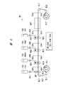
- FIG. 6 is a schematic diagram of an apparatus for manufacturing an electrode sheet for a lithium ion battery according to the third embodiment.
- FIG. 7 is a cross-sectional view of the electrode sheet in each coating step and drying step for explaining the method of manufacturing the electrode sheet of the lithium ion battery in the third embodiment.
- 7A is a cross-sectional view of the electrode sheet in the first insulating material (spacer material) application step (cross-sectional view of A3-A3 in FIG. 6)
- FIG. 7B is an electrode sheet in the first electrode material application step.
- FIG. 7 is a cross-sectional view of the electrode sheet in the second insulating material (separator material) application step (cross-sectional view of D3-D3 in FIG. 6)
- FIG. 7E is a cross-sectional view of the electrode sheet in the drying step.
- FIG. 7 is a sectional view taken along line E3-E3 in FIG.
- Embodiment 3 exemplifies a method for manufacturing a positive electrode film formed in two rows on the surface of the current collector foil along the first direction in which the current collector foil travels. Moreover, in this Embodiment 3, although the manufacturing method of the single side
- the current collector foil PEP is fed from the unwinding roll SL1, and the first roller RL1, the second roller RL2, the third roller RL3, the fourth roller RL4,
- the paper is conveyed to the take-up roll SL2 by the 5-roller RL5, the sixth roller RL6, the seventh roller RL7, and the eighth roller RL8.
- a dispenser DP is installed facing the third roller RL3, a first slit die coater DC1 is installed facing the fourth roller RL4, a second slit die coater DC2 is installed facing the fifth roller RL5, and the sixth
- a third slit die coater DC3 is installed facing the roller RL6.
- First coating process First insulating material (spacer material) coating process
- First, the first insulating material IF1 is applied to the surface of the current collector foil PEP in the same manner as the application process (first insulating material (separator material) applying process) of the first embodiment described above.
- insulating material IF1 is in the 2nd direction orthogonal to the surface of the current collection foil PEP which runs in the 1st direction at the surface of the 1st direction and the current collection foil PEP. They are applied separately from each other. That is, the plurality of first insulating materials IF1 sandwich the region in which the positive electrode material PAS is applied on the surface of the current collector foil PEP traveling in the first direction in the second and third application steps in the second direction. To the surface of the current collector foil PEP.
- the plurality of first insulating materials IF1 has the width in the second direction of the region of the positive electrode material PAS applied to the surface of the current collector foil PEP that travels in the first direction in the second and third application steps. Applied to regulate.
- the plurality of first insulating materials IF1 are separated from each other in the second direction, and the current collector foil Three rows are applied to the surface of the PEP along the first direction.
- the thickness of the first insulating material IF1 is substantially the same as the thickness of the positive electrode material PAS applied to the surface of the current collector foil PEP in the subsequent second and third application steps.
- the region to which the first insulating material IF1 is applied is a region that is cut after the positive electrode sheet is completed, the width in the second direction of the first insulating material IF1 is set to be small in order to reduce the material cost.
- the width in the second direction of the first insulating material IF1 is about 5 to 15 mm.
- Second application process (first electrode material application process)
- the slurry-like first positive electrode material PAS1 supplied from the first slit die coater DC1 at a position facing the fourth roller RL4 is applied to the surface of the current collector foil PEP fed from the unwinding roll SL1.
- the first positive electrode material PAS1 is stored in the tank TA2, and is supplied to the surface of the current collector foil PEP by the metering pump PU2.
- the plurality of first positive electrode materials PAS1 are applied to the surface of the current collector foil PEP traveling in the first direction and to the surface of the current collector foil PEP in the previous first application step. It is applied to a region sandwiched between the first insulating materials IF1.
- the plurality of first positive electrode materials PAS1 are separated by the first insulating material IF1 and second Two rows are applied along the first direction to the surface of the current collector foil PEP.
- the thickness of the first positive electrode material PAS1 is smaller than the thickness of the first insulating material IF1 applied to the surface of the current collector foil PEP in the previous first application step. That is, the upper surface of the first positive electrode material PAS1 is at a position lower than the upper surface of the first insulating material IF1.
- the thickness of the first positive electrode material PAS1 can be adjusted, for example, by adjusting the height of the base D1 of the first slit die coater DC1 (see FIG. 10) and feeding the first positive electrode material PAS1.
- Second electrode material application process Next, the slurry-like second positive electrode material PAS2 supplied from the second slit die coater DC2 at a position facing the fifth roller RL5 is applied to the surface of the current collector foil PEP fed from the unwinding roll SL1.
- the second positive electrode material PAS2 is stored in the tank TA3, and is supplied to the upper surface of the first positive electrode material PAS1 by the metering pump PU3.
- the binder content of the second positive electrode material PAS2 is smaller than the binder content of the first positive electrode material PAS1.
- the second positive electrode material PAS2 is applied to the upper surface of the first positive electrode material PAS1, and the positive electrode material PAS formed by laminating the first positive electrode material PAS1 and the second positive electrode material PAS2 is formed. It is formed.
- the second positive electrode material PAS2 is applied so that the height from the surface of the current collector foil PEP to the upper surface of the positive electrode material PAS is substantially the same as the height from the surface of the current collector foil PEP to the upper surface of the first insulating material IF1.
- the thickness of the positive electrode material PAS is substantially the same as the thickness of the first insulating material IF1 applied to the surface of the current collector foil PEP in the previous first application step.
- the thickness of the positive electrode material PAS and the thickness of the first insulating material IF1 are desirably the same, in order to prevent the second positive electrode material PAS2 from being applied to the upper surface of the first insulating material IF1,
- the second positive electrode material PAS2 is applied so as to be lower by about 0 ⁇ m to 10 ⁇ m than the upper surface of the first insulating material IF1.
- the thickness of the second positive electrode material PAS2 can be adjusted, for example, by adjusting the height of the die D1 of the second slit die coater DC2 (see FIG. 10) and the feed amount of the second positive electrode material PAS2.
- the positive electrode material PAS is configured by laminating the first positive electrode material PAS1 and the second positive electrode material PAS2 having different binder contents. This is due to the following reason.
- the slurry-like positive electrode material PAS contains a binder for binding the active material and the conductive auxiliary agent in addition to the active material and the conductive auxiliary agent.
- this binder tends to segregate on the upper surface side of the positive electrode material PAS in the drying process, and if the binder content is too small, this causes the positive electrode material PAS at the interface between the current collector foil PEP and the positive electrode material PAS. May peel off.
- the positive electrode material PAS is thickly coated, the segregation of the binder becomes remarkable, and the peeling of the positive electrode material PAS becomes a serious problem.
- the segregation of the binder can be made difficult to occur.
- the binder content is too large, the amount of the active material is reduced and the battery capacity is lowered, or the binder is difficult to mix, and thus the current distribution of the positive electrode film varies.
- the viscosity and surface tension of the positive electrode material PAS there is also a trade-off between the viscosity and surface tension of the positive electrode material PAS, and it is difficult to adjust the binder content contained in the positive electrode material PAS to the optimum content.
- the positive electrode material PAS is thickly coated Therefore, it becomes more difficult to adjust the binder content.
- the first positive electrode material PAS1 having a relatively high binder content is applied, and the second positive electrode material PAS2 having a relatively low binder content is applied thereon.
- the first positive electrode material PAS1 and the second positive electrode material PAS2 are mixed, but when the positive electrode material PAS is coated with two layers of the first positive electrode material PAS1 and the second positive electrode material PAS2, Since the segregation of the binder on the upper surface side of the positive electrode material PAS is less than when the positive electrode material PAS is coated, in the third embodiment, the positive electrode material PAS can be prevented from peeling off.
- the first positive electrode material PAS1 and the second positive electrode material PAS2 having such viscosity and surface tension that the side surfaces of the first positive electrode material PAS1 and the second positive electrode material PAS2 are inclined. May have to be used.
- the first insulating material IF1 prescribes the region where the first positive electrode material PAS1 and the second positive electrode material PAS2 are applied. The shapes of the positive electrode material PAS1 and the second positive electrode material PAS2 are stable.
- Fourth coating process (second insulating material (separator material) coating process)
- the second insulating material IF2 is applied.
- the second insulating material IF2 is stored in the tank TA4, and is supplied to the upper surfaces of the first insulating material IF1 and the second positive electrode material PAS2 by the metering pump PU4.
- the second insulating material IF2 is applied to the upper surfaces of the first insulating material IF1 and the positive electrode material PAS along the first direction in which the current collector foil PEP travels.
- the thickness of the second insulating material IF2 is, for example, about 5 ⁇ m to 40 ⁇ m.
- the thickness of the second insulating material IF2 can be adjusted, for example, by adjusting the height of the base D1 of the third slit die coater DC3 (see FIG. 10) and feeding the second insulating material IF2.
- the second insulating material IF2 is applied to the upper surfaces of the first insulating material IF1 and the positive electrode material PAS, which are substantially flat surfaces, for example, the side surfaces of the first insulating material IF1 and the positive electrode material PAS,
- the first insulating material IF1 and the positive electrode material PAS are not applied to the surface of the current collector foil PEP to which the first insulating material IF1 and the positive electrode material PAS are not applied. Therefore, since the second insulating material IF2 can be uniformly applied, it is possible to prevent the second insulating material IF2 from being cut.
- the positive electrode material PAS and the first insulating material IF1 applied to the surface of the current collector foil PEP by passing through the drying furnace (drying mechanism) DRY The entire coating film obtained by laminating the second insulating material IF2 applied to these upper surfaces is dried, and the current collector foil PEP having the positive electrode film and the separator formed on the surface is wound on the winding roll SL2.
- the first positive electrode material PAS1 and the second positive electrode material PAS2 are mixed to form a single-layer positive electrode material PAS.
- the thickness of the positive electrode material PAS and the thickness of the first insulating material IF1 were substantially the same before drying, but after drying, the amount of solids contained in the first positive electrode material PAS1 and the second positive electrode material PAS2
- the thickness of the spacer SP made of the first insulating material IF1 is thinner than the thickness of the positive electrode film PE made of the positive electrode material PAS because of the difference between the amount of the solid matter contained in the first insulating material IF1.
- the method of manufacturing the positive electrode film PE formed in two rows on the surface of the current collector foil PEP along the first direction in which the current collector foil PEP travels is exemplified, but the present invention is not limited thereto. It is not something.
- the positive electrode film PE may be one row or three or more rows, and the same effect can be obtained.
- the positive electrode material PAS is configured by two layers of the first positive electrode material PAS1 and the second positive electrode material PAS2 having different binder contents.
- the positive electrode material PAS may be composed of three or more layers having different contents.
- the third embodiment by forming the positive electrode material PAS by stacking the first positive electrode material PAS1 and the second positive electrode material PAS2, the segregation of the binder on the upper surface side of the positive electrode material PAS is reduced. Thus, peeling of the positive electrode material PAS can be prevented.
- the region where the first positive electrode material PAS1 and the second positive electrode material PAS2 are applied is defined in advance by the first insulating material IF1, the shapes of the first positive electrode material PAS1 and the second positive electrode material PAS2 are stable.
- the film of the second insulating material IF2 does not break, so that the second insulating material IF2 can be thinly and uniformly applied. Thereby, it is possible to reduce the thickness of the separator SE and the electrode film without reducing the production yield of the lithium ion battery.
Landscapes
- Chemical & Material Sciences (AREA)
- Engineering & Computer Science (AREA)
- Chemical Kinetics & Catalysis (AREA)
- Electrochemistry (AREA)
- General Chemical & Material Sciences (AREA)
- Manufacturing & Machinery (AREA)
- Materials Engineering (AREA)
- Battery Electrode And Active Subsutance (AREA)
- Cell Separators (AREA)
- Secondary Cells (AREA)
Abstract
Description
まず、本実施の形態によるリチウムイオン電池の製造装置および製造方法がより明確となると思われるため、比較例として、本発明者らによって検討された、本願発明が適用される前のリチウムイオン電池の製造装置および製造方法について以下に説明する。
≪リチウムイオン電池の電極シートの製造方法≫
本実施の形態1におけるリチウムイオン電池の電極シートの製造方法を図1および図2を用いて説明する。図1は、本実施の形態1におけるリチウムイオン電池の電極シートの製造装置の概略図である。図2は、本実施の形態1におけるリチウムイオン電池の電極シートの製造方法を説明する各塗布工程および乾燥工程の電極シートの断面図である。図2(a)は第1絶縁材料(スペーサ材料)塗布工程の電極シートの断面図(図1のA1-A1の断面図)、図2(b)は電極材料塗布工程の電極シートの断面図(図1のB1-B1の断面図)および図2(c)は第2絶縁材料(セパレータ材料)塗布工程の電極シートの断面図(図1のC1-C1の断面図)である。さらに、図2(d)は乾燥工程の電極シートの断面図(図1のD1-D1の断面図)である。
まず、巻き出しロールSL1から送り出された集電箔PEPの表面に、第3ローラRL3と対向した位置のディスペンサDPから供給されるスラリー状の第1絶縁材料IF1が塗布される。第1絶縁材料IF1はタンクTA1に貯留されており、定量ポンプPU1によって集電箔PEPの表面に供給される。
次に、巻き出しロールSL1から送り出された集電箔PEPの表面に、第4ローラRL4と対向した位置の第1スリットダイコータDC1から供給されるスラリー状の正極材料PASが塗布される。正極材料PASはタンクTA2に貯留されており、定量ポンプPU2によって集電箔PEPの表面に供給される。
次に、第5ローラRL5と対向した位置の第2スリットダイコータDC2から供給されるスラリー状の第2絶縁材料IF2が塗布される。第2絶縁材料IF2はタンクTA3に貯留されており、定量ポンプPU3によって第1絶縁材料IF1および正極材料PASの上面に供給される。
次に、乾燥炉(乾燥機構)DRYを通過することで、集電箔PEPの表面に塗布した正極材料PASおよび第1絶縁材料IF1と、これらの上面に塗布した第2絶縁材料IF2とを積層した塗膜の全体が乾燥し、その表面に正極膜およびセパレータが形成された集電箔PEPが巻き取りロールSL2に巻き取られる。
本実施の形態1におけるリチウムイオン電池の具体的な製造工程を図3を用いて説明する。図3は、本実施の形態1におけるリチウムイオン電池の具体的な製造工程をまとめた工程図である。
本実施の形態1で用いる正極活物質には、例えばコバルト酸リチウムまたはMn(マンガン)を含有するスピネル構造のリチウム含有複合酸化物を用いることができる。また、正極活物質には、Ni(ニッケル)、Co(コバルト)およびMn(マンガン)を含む複合酸化物、またはオリビン型リン酸鉄に代表されるオリビン型化合物などを用いることもできる。ただし、正極活物質に用いる材料は、これらに限定されるものではない。
前述の実施の形態1と相違する点は、スペーサとなる第1絶縁材料を塗布する工程と、電極膜となる電極材料を塗布する工程との工程順である。すなわち、前述の実施の形態1では、第1絶縁材料IF1を集電箔PEPの表面に塗布した後、正極材料PASを集電箔PEPの表面に塗布したが、本実施の形態2では、正極材料PASを集電箔PEPの表面に塗布した後、第1絶縁材料IF1を集電箔PEPの表面に塗布する。
本実施の形態2におけるリチウムイオン電池の電極シートの製造方法を図4および図5を用いて説明する。図4は、本実施の形態2におけるリチウムイオン電池の電極シートの製造装置の概略図である。図5は、本実施の形態2におけるリチウムイオン電池の電極シートの製造方法を説明する各塗布工程および乾燥工程の電極シートの断面図である。図5(a)は電極材料塗布工程の電極シートの断面図(図4のA2-A2の断面図)、図5(b)は第1絶縁材料(スペーサ材料)塗布工程の電極シートの断面図(図4のB2-B2の断面図)および図5(c)は第2絶縁材料(セパレータ材料)塗布工程の電極シートの断面図(図4のC2-C2の断面図)である。さらに、図5(d)は乾燥工程の電極シートの断面図(図4のD2-D2の断面図)である。
まず、巻き出しロールSL1から送り出された集電箔PEPの表面に、第3ローラRL3と対向した位置の第1スリットダイコータDC1から供給されるスラリー状の正極材料PASが塗布される。正極材料PASはタンクTA1に貯留されており、定量ポンプPU1によって集電箔PEPの表面に供給される。
次に、巻き出しロールSL1から送り出された集電箔PEPの表面に、第4ローラRL4と対向した位置のディスペンサDPから供給されるスラリー状の第1絶縁材料IF1が塗布される。第1絶縁材料IF1はタンクTA2に貯留されており、定量ポンプPU2によって集電箔PEPの表面に供給される。
次に、前述の実施の形態1の第3塗布工程(第2絶縁材料(セパレータ材料)塗布工程)と同様に、第5ローラRL5と対向した位置の第2スリットダイコータDC2から供給されるスラリー状の第2絶縁材料IF2が塗布される。第2絶縁材料IF2はタンクTA3に貯留されており、定量ポンプPU3によって第1絶縁材料IF1および正極材料PASの上面に供給される。
次に、前述の実施の形態1の乾燥工程と同様に、乾燥炉(乾燥機構)DRYを通過することで、集電箔PEPの表面に塗布した正極材料PASおよび第1絶縁材料IF1と、これらの上面に塗布した第2絶縁材料IF2とを積層した塗膜の全体が乾燥し、その表面に正極膜およびセパレータが形成された集電箔PEPが巻き取りロールSL2に巻き取られる。
前述の実施の形態1と相違する点は、電極材料を塗布する工程数である。すなわち、前述の実施の形態1では、一度の塗布工程によって、正極材料PASを集電箔PEPの表面に塗布したが、本実施の形態3では、二度の塗布工程によって、正極材料PASを集電箔PEPの表面に塗布する。
本実施の形態3におけるリチウムイオン電池の電極シートの製造方法を図6および図7を用いて説明する。図6は、本実施の形態3におけるリチウムイオン電池の電極シートの製造装置の概略図である。図7は、本実施の形態3におけるリチウムイオン電池の電極シートの製造方法を説明する各塗布工程および乾燥工程の電極シートの断面図である。図7(a)は第1絶縁材料(スペーサ材料)塗布工程の電極シートの断面図(図6のA3-A3の断面図)、図7(b)は第1電極材料塗布工程の電極シートの断面図(図6のB3-B3の断面図)および図7(c)は第2電極材料塗布工程の電極シートの断面図(図6のC3-C3の断面図)である。さらに、図7(d)は第2絶縁材料(セパレータ材料)塗布工程の電極シートの断面図(図6のD3-D3の断面図)および図7(e)は乾燥工程の電極シートの断面図(図6のE3-E3の断面図)である。
まず、前述の実施の形態1の塗布工程(第1絶縁材料(セパレータ材料)塗布工程)と同様に、集電箔PEPの表面に第1絶縁材料IF1が塗布される。
次に、巻き出しロールSL1から送り出された集電箔PEPの表面に、第4ローラRL4と対向した位置の第1スリットダイコータDC1から供給されるスラリー状の第1正極材料PAS1が塗布される。第1正極材料PAS1はタンクTA2に貯留されており、定量ポンプPU2によって集電箔PEPの表面に供給される。
次に、巻き出しロールSL1から送り出された集電箔PEPの表面に、第5ローラRL5と対向した位置の第2スリットダイコータDC2から供給されるスラリー状の第2正極材料PAS2が塗布される。第2正極材料PAS2はタンクTA3に貯留されており、定量ポンプPU3によって第1正極材料PAS1の上面に供給される。ここで、第2正極材料PAS2のバインダの含有量は、第1正極材料PAS1のバインダの含有量よりも少ない。
次に、前述の実施の形態1の第3塗布工程(第2絶縁材料(セパレータ材料)塗布工程)と同様に、第6ローラRL6と対向した位置の第3スリットダイコータDC3から供給されるスラリー状の第2絶縁材料IF2が塗布される。第2絶縁材料IF2はタンクTA4に貯留されており、定量ポンプPU4によって第1絶縁材料IF1および第2正極材料PAS2の上面に供給される。
次に、前述の実施の形態1の乾燥工程と同様に、乾燥炉(乾燥機構)DRYを通過することで、集電箔PEPの表面に塗布した正極材料PASおよび第1絶縁材料IF1と、これらの上面に塗布した第2絶縁材料IF2とを積層した塗膜の全体が乾燥し、その表面に正極膜およびセパレータが形成された集電箔PEPが巻き取りロールSL2に巻き取られる。
D2 マニホールド
D3 スリット部
D4 電極材料溜り
D5 下流側メニスカス(液面の屈曲)
D6 下流側リップ部
DC1 第1スリットダイコータ
DC2 第2スリットダイコータ
DC3 第3スリットダイコータ
DP ディスペンサ
DRY 乾燥炉
h1 第1間隔
IF 絶縁材料
IF1 第1絶縁材料
IF2 第2絶縁材料
M1 電極シート製造装置
M2 電極シート製造装置
M3 電極シート製造装置
PAS 正極材料
PAS1 第1正極材料
PAS2 第2正極材料
PE 正極膜
PEP 集電箔
PU1,PU2,PU3,PU4 定量ポンプ
RL1 第1ローラ
RL2 第2ローラ
RL3 第3ローラ
RL4 第4ローラ
RL5 第5ローラ
RL6 第6ローラ
RL7 第7ローラ
RL8 第8ローラ
SE セパレータ
SL1 巻き出しロール
SL2 巻き取りロール
SP スペーサ
TA1,TA2,TA3,TA4 タンク
Claims (12)
- 集電箔を第1方向に搬送する搬送機構と、
前記集電箔の表面で、かつ前記第1方向と前記集電箔の表面で直交する第2方向に互いに離間する複数の第1領域に、スラリー状の第1絶縁材料を塗布する第1塗布機構と、
前記集電箔の表面で、かつ前記第2方向に隣り合う前記第1領域に挟まれる第2領域に、スラリー状の第1電極材料を塗布する第2塗布機構と、
前記第1絶縁材料および前記第1電極材料の上面にスラリー状の第2絶縁材料を塗布する第3塗布機構と、
を備える、蓄電デバイスの製造装置。 - 請求項1記載の蓄電デバイスの製造装置において、
前記第1電極材料、前記第1絶縁材料および前記第2絶縁材料を乾燥させる乾燥機構、
をさらに備える、蓄電デバイスの製造装置。 - 請求項1記載の蓄電デバイスの製造装置において、
前記第1方向に、前記第1塗布機構、前記第2塗布機構および前記第3塗布機構が順に設置されている、蓄電デバイスの製造装置。 - 請求項3記載の蓄電デバイスの製造装置において、
前記第2塗布機構と前記第3塗布機構との間に、
前記第1電極材料の上面に、スラリー状の第2電極材料を塗布する第4塗布機構、
をさらに備える、蓄電デバイスの製造装置。 - 請求項1記載の蓄電デバイスの製造装置において、
前記第1方向に、前記第2塗布機構、前記第1塗布機構および前記第3塗布機構が順に設置されている、蓄電デバイスの製造装置。 - 請求項1から請求項5のいずれか1項に記載の蓄電デバイスの製造装置において、
前記第1塗布機構はディスペンサを有し、前記第2塗布機構および前記第3塗布機構はスリットダイコータを有する、蓄電デバイスの製造装置。 - (a)第1方向に走行する集電箔の表面に、前記第1方向と前記集電箔の表面で直交する第2方向に互いに離間する複数のスラリー状の第1絶縁材料を塗布する工程、
(b)前記(a)工程の後、前記第2方向に隣り合う前記第1絶縁材料に挟まれる前記集電箔の表面に、スラリー状の電極材料を塗布する工程、
(c)前記(b)工程の後、前記電極材料および前記第1絶縁材料の上面にスラリー状の第2絶縁材料を塗布する工程、
(d)前記(c)工程の後、前記電極材料、前記第1絶縁材料および前記第2絶縁材料を乾燥させる工程、
を有する、蓄電デバイスの製造方法。 - (a)第1方向に走行する集電箔の表面に、スラリー状の電極材料を塗布する工程、
(b)前記(a)工程の後、前記第1方向と前記集電箔の表面で直交する第2方向の前記電極材料の両側の前記集電箔の表面に、スラリー状の第1絶縁材料を塗布する工程、
(c)前記(b)工程の後、前記電極材料および前記第1絶縁材料の上面にスラリー状の第2絶縁材料を塗布する工程、
(d)前記(c)工程の後、前記電極材料、前記第1絶縁材料および前記第2絶縁材料を乾燥させる工程、
を有する、蓄電デバイスの製造方法。 - 請求項7記載の蓄電デバイスの製造方法において、
前記(b)工程では、バインダの含有量が互いに異なる複数の電極材料が積層される、蓄電デバイスの製造方法。 - 請求項7または8記載の蓄電デバイスの製造方法において、
前記第1絶縁材料の前記第2方向の幅は5mmから15mm程度である、蓄電デバイスの製造方法。 - 請求項7または8記載の蓄電デバイスの製造方法において、
前記(b)工程では、前記電極材料の上面が前記第1絶縁材料の上面よりも0μmから10μm低い、蓄電デバイスの製造方法。 - 請求項7または8記載の蓄電デバイスの製造方法において、
前記(c)工程で塗布される前記第2絶縁材料の厚さは5μmから40μmである、蓄電デバイスの製造方法。
Priority Applications (2)
| Application Number | Priority Date | Filing Date | Title |
|---|---|---|---|
| KR1020167006332A KR101773728B1 (ko) | 2014-03-26 | 2014-09-02 | 축전 디바이스의 제조 장치 및 축전 디바이스의 제조 방법 |
| CN201480050428.5A CN105531855B (zh) | 2014-03-26 | 2014-09-02 | 蓄电装置的制造装置及蓄电装置的制造方法 |
Applications Claiming Priority (2)
| Application Number | Priority Date | Filing Date | Title |
|---|---|---|---|
| JP2014-064851 | 2014-03-26 | ||
| JP2014064851A JP6121353B2 (ja) | 2014-03-26 | 2014-03-26 | 蓄電デバイスの製造装置および蓄電デバイスの製造方法 |
Publications (1)
| Publication Number | Publication Date |
|---|---|
| WO2015145806A1 true WO2015145806A1 (ja) | 2015-10-01 |
Family
ID=54194385
Family Applications (1)
| Application Number | Title | Priority Date | Filing Date |
|---|---|---|---|
| PCT/JP2014/072970 Ceased WO2015145806A1 (ja) | 2014-03-26 | 2014-09-02 | 蓄電デバイスの製造装置および蓄電デバイスの製造方法 |
Country Status (4)
| Country | Link |
|---|---|
| JP (1) | JP6121353B2 (ja) |
| KR (1) | KR101773728B1 (ja) |
| CN (1) | CN105531855B (ja) |
| WO (1) | WO2015145806A1 (ja) |
Cited By (5)
| Publication number | Priority date | Publication date | Assignee | Title |
|---|---|---|---|---|
| US11495781B2 (en) * | 2020-08-05 | 2022-11-08 | Hyundai Motor Company | System and method for manufacturing positive electrode for secondary battery |
| US20240243245A1 (en) * | 2021-11-29 | 2024-07-18 | Contemporary Amperex Technology Co., Limited | Electrode plate forming apparatus |
| US12125984B2 (en) | 2020-10-09 | 2024-10-22 | 24M Technologies, Inc. | Methods of continuous and semi-continuous production of electrochemical cells |
| US12176519B2 (en) | 2018-07-09 | 2024-12-24 | 24M Technologies, Inc. | Continuous and semi-continuous methods of semi-solid electrode and battery manufacturing |
| EP4521476A1 (en) * | 2023-09-08 | 2025-03-12 | LG Energy Solution, Ltd. | Method of processing metal foil web material into an electrode web |
Families Citing this family (6)
| Publication number | Priority date | Publication date | Assignee | Title |
|---|---|---|---|---|
| CN105964485A (zh) * | 2016-06-11 | 2016-09-28 | 深圳市新嘉拓自动化技术有限公司 | 帘式涂布供胶机构 |
| JP7279298B2 (ja) * | 2017-03-06 | 2023-05-23 | 株式会社リコー | 電極 |
| EP4567936A3 (en) | 2017-03-06 | 2025-09-03 | Ricoh Company, Ltd. | Film electrode, resin layer forming ink and electrode printing method |
| CN113363667A (zh) * | 2021-05-06 | 2021-09-07 | 惠州锂威新能源科技有限公司 | 一种电池隔膜的生产设备及隔膜 |
| KR20250107514A (ko) * | 2024-01-05 | 2025-07-14 | 주식회사 엘지에너지솔루션 | 이차 전지 제조 설비 및 이차 전지를 제조하는 방법 |
| CN119480875A (zh) * | 2024-10-23 | 2025-02-18 | 北京理工大学 | 一种用于碳纤维电极活性物质涂敷及cvd生长的装置和方法 |
Citations (8)
| Publication number | Priority date | Publication date | Assignee | Title |
|---|---|---|---|---|
| JP2004253353A (ja) * | 2002-12-27 | 2004-09-09 | Matsushita Electric Ind Co Ltd | 電気化学素子の製造方法 |
| WO2005081336A1 (ja) * | 2004-02-20 | 2005-09-01 | Matsushita Electric Industrial Co., Ltd. | リチウムイオン二次電池の製造法 |
| JP2009262070A (ja) * | 2008-04-25 | 2009-11-12 | Panasonic Corp | 被膜形成装置、被膜形成方法、電池用極板、並びに非水電解液二次電池 |
| WO2011138920A1 (ja) * | 2010-05-07 | 2011-11-10 | 日産自動車株式会社 | 電極構造体、その製造方法及び双極型電池 |
| JP2012015039A (ja) * | 2010-07-05 | 2012-01-19 | Konica Minolta Holdings Inc | セパレータ一体型電極、セパレータ一体型電極の製造方法、およびリチウムイオン二次電池 |
| JP2012022827A (ja) * | 2010-07-13 | 2012-02-02 | Dainippon Screen Mfg Co Ltd | 電池の製造方法、電池、車両および電子機器 |
| JP2013105680A (ja) * | 2011-11-15 | 2013-05-30 | Toyota Motor Corp | 二次電池 |
| JP2013188663A (ja) * | 2012-03-13 | 2013-09-26 | Toppan Printing Co Ltd | 間欠塗布装置 |
Family Cites Families (5)
| Publication number | Priority date | Publication date | Assignee | Title |
|---|---|---|---|---|
| US7335448B2 (en) * | 2002-05-30 | 2008-02-26 | Matsushita Electric Industrial Co., Ltd. | Lithium ion secondary battery |
| JP4201619B2 (ja) * | 2003-02-26 | 2008-12-24 | 三洋電機株式会社 | 非水電解質二次電池、及びそれに使用する電極の製造方法 |
| KR101506284B1 (ko) * | 2012-04-19 | 2015-03-26 | 주식회사 엘지화학 | 다층 구조 전극 및 이를 포함하는 리튬 이차전지 |
| JP5875487B2 (ja) * | 2012-08-29 | 2016-03-02 | 株式会社日立製作所 | リチウムイオン二次電池の製造方法及び製造装置 |
| JP2014078439A (ja) * | 2012-10-11 | 2014-05-01 | Toyota Industries Corp | 電極の製造方法 |
-
2014
- 2014-03-26 JP JP2014064851A patent/JP6121353B2/ja not_active Expired - Fee Related
- 2014-09-02 KR KR1020167006332A patent/KR101773728B1/ko not_active Expired - Fee Related
- 2014-09-02 WO PCT/JP2014/072970 patent/WO2015145806A1/ja not_active Ceased
- 2014-09-02 CN CN201480050428.5A patent/CN105531855B/zh not_active Expired - Fee Related
Patent Citations (8)
| Publication number | Priority date | Publication date | Assignee | Title |
|---|---|---|---|---|
| JP2004253353A (ja) * | 2002-12-27 | 2004-09-09 | Matsushita Electric Ind Co Ltd | 電気化学素子の製造方法 |
| WO2005081336A1 (ja) * | 2004-02-20 | 2005-09-01 | Matsushita Electric Industrial Co., Ltd. | リチウムイオン二次電池の製造法 |
| JP2009262070A (ja) * | 2008-04-25 | 2009-11-12 | Panasonic Corp | 被膜形成装置、被膜形成方法、電池用極板、並びに非水電解液二次電池 |
| WO2011138920A1 (ja) * | 2010-05-07 | 2011-11-10 | 日産自動車株式会社 | 電極構造体、その製造方法及び双極型電池 |
| JP2012015039A (ja) * | 2010-07-05 | 2012-01-19 | Konica Minolta Holdings Inc | セパレータ一体型電極、セパレータ一体型電極の製造方法、およびリチウムイオン二次電池 |
| JP2012022827A (ja) * | 2010-07-13 | 2012-02-02 | Dainippon Screen Mfg Co Ltd | 電池の製造方法、電池、車両および電子機器 |
| JP2013105680A (ja) * | 2011-11-15 | 2013-05-30 | Toyota Motor Corp | 二次電池 |
| JP2013188663A (ja) * | 2012-03-13 | 2013-09-26 | Toppan Printing Co Ltd | 間欠塗布装置 |
Cited By (7)
| Publication number | Priority date | Publication date | Assignee | Title |
|---|---|---|---|---|
| US12176519B2 (en) | 2018-07-09 | 2024-12-24 | 24M Technologies, Inc. | Continuous and semi-continuous methods of semi-solid electrode and battery manufacturing |
| US11495781B2 (en) * | 2020-08-05 | 2022-11-08 | Hyundai Motor Company | System and method for manufacturing positive electrode for secondary battery |
| US12132189B2 (en) | 2020-08-05 | 2024-10-29 | Hyundai Motor Company | System and method for manufacturing positive electrode for secondary battery |
| US12125984B2 (en) | 2020-10-09 | 2024-10-22 | 24M Technologies, Inc. | Methods of continuous and semi-continuous production of electrochemical cells |
| US20240243245A1 (en) * | 2021-11-29 | 2024-07-18 | Contemporary Amperex Technology Co., Limited | Electrode plate forming apparatus |
| US12506136B2 (en) * | 2021-11-29 | 2025-12-23 | Contemporary Amperex Technology (Hong Kong) Limited | Electrode plate forming apparatus |
| EP4521476A1 (en) * | 2023-09-08 | 2025-03-12 | LG Energy Solution, Ltd. | Method of processing metal foil web material into an electrode web |
Also Published As
| Publication number | Publication date |
|---|---|
| JP6121353B2 (ja) | 2017-04-26 |
| KR101773728B1 (ko) | 2017-08-31 |
| CN105531855B (zh) | 2018-02-16 |
| KR20160042088A (ko) | 2016-04-18 |
| JP2015187943A (ja) | 2015-10-29 |
| CN105531855A (zh) | 2016-04-27 |
Similar Documents
| Publication | Publication Date | Title |
|---|---|---|
| JP6121353B2 (ja) | 蓄電デバイスの製造装置および蓄電デバイスの製造方法 | |
| US9105931B2 (en) | Positive electrode plate for use in lithium ion secondary battery, lithium ion secondary battery, vehicle, device with battery mounted thereon, and method for producing positive electrode plate for lithium ion secondary battery | |
| KR101660189B1 (ko) | 리튬 이온 이차 전지의 제조 방법 및 제조 장치 | |
| WO2020066254A1 (ja) | リチウム二次電池 | |
| JP6613647B2 (ja) | 蓄電デバイス用電極の製造方法および前記電極の製造装置 | |
| CN115336076A (zh) | 锂二次电池 | |
| CN115885404A (zh) | 锂二次电池 | |
| CN105531865B (zh) | 锂离子二次电池的制造方法、锂离子二次电池的制造装置和锂离子二次电池 | |
| CN104011907B (zh) | 电极的制造方法以及非水电解质电池的制造方法 | |
| WO2014136714A1 (ja) | 非水電解液二次電池 | |
| CN103270625B (zh) | 锂离子二次电池 | |
| JP2013051040A (ja) | 電池用電極の製造方法及び電池用電極 | |
| US20200251726A1 (en) | Multilayered electrodes having high charge and discharge rates | |
| CN105283999A (zh) | 二次电池和电极制造方法 | |
| CN108365164B (zh) | 电池的制造方法 | |
| CN109565069B (zh) | 电极组件及其制造方法 | |
| WO2016111063A1 (ja) | リチウムイオン電池およびその製造方法、並びにリチウムイオン電池の製造装置 | |
| US20200161628A1 (en) | Layered electrode with high rate top layer | |
| CN104067423A (zh) | 电极的制造方法以及非水电解质电池的制造方法 | |
| CN111868971A (zh) | 用于二次电池的电极、使用所述电极的二次电池及其制造方法 | |
| JP6021775B2 (ja) | リチウムイオン二次電池の製造方法およびリチウムイオン二次電池の製造装置 | |
| WO2019198495A1 (ja) | 電池の製造方法 | |
| JP6081333B2 (ja) | リチウムイオン二次電池の製造方法およびリチウムイオン二次電池の製造装置 | |
| JP7302593B2 (ja) | リチウムポリマー電池 | |
| JP6128228B2 (ja) | 負極活物質、それを用いた負極、及びリチウムイオン二次電池 |
Legal Events
| Date | Code | Title | Description |
|---|---|---|---|
| WWE | Wipo information: entry into national phase |
Ref document number: 201480050428.5 Country of ref document: CN |
|
| 121 | Ep: the epo has been informed by wipo that ep was designated in this application |
Ref document number: 14887014 Country of ref document: EP Kind code of ref document: A1 |
|
| ENP | Entry into the national phase |
Ref document number: 20167006332 Country of ref document: KR Kind code of ref document: A |
|
| NENP | Non-entry into the national phase |
Ref country code: DE |
|
| 122 | Ep: pct application non-entry in european phase |
Ref document number: 14887014 Country of ref document: EP Kind code of ref document: A1 |