WO2015141797A1 - 樹脂組成物、樹脂シート、樹脂シート硬化物、樹脂シート積層体、樹脂シート積層体硬化物及びその製造方法、半導体装置並びにled装置 - Google Patents
樹脂組成物、樹脂シート、樹脂シート硬化物、樹脂シート積層体、樹脂シート積層体硬化物及びその製造方法、半導体装置並びにled装置 Download PDFInfo
- Publication number
- WO2015141797A1 WO2015141797A1 PCT/JP2015/058334 JP2015058334W WO2015141797A1 WO 2015141797 A1 WO2015141797 A1 WO 2015141797A1 JP 2015058334 W JP2015058334 W JP 2015058334W WO 2015141797 A1 WO2015141797 A1 WO 2015141797A1
- Authority
- WO
- WIPO (PCT)
- Prior art keywords
- resin
- resin sheet
- epoxy resin
- cured
- resin composition
- Prior art date
Links
Images


Classifications
-
- B—PERFORMING OPERATIONS; TRANSPORTING
- B32—LAYERED PRODUCTS
- B32B—LAYERED PRODUCTS, i.e. PRODUCTS BUILT-UP OF STRATA OF FLAT OR NON-FLAT, e.g. CELLULAR OR HONEYCOMB, FORM
- B32B27/00—Layered products comprising a layer of synthetic resin
- B32B27/38—Layered products comprising a layer of synthetic resin comprising epoxy resins
-
- B—PERFORMING OPERATIONS; TRANSPORTING
- B32—LAYERED PRODUCTS
- B32B—LAYERED PRODUCTS, i.e. PRODUCTS BUILT-UP OF STRATA OF FLAT OR NON-FLAT, e.g. CELLULAR OR HONEYCOMB, FORM
- B32B15/00—Layered products comprising a layer of metal
- B32B15/04—Layered products comprising a layer of metal comprising metal as the main or only constituent of a layer, which is next to another layer of the same or of a different material
- B32B15/08—Layered products comprising a layer of metal comprising metal as the main or only constituent of a layer, which is next to another layer of the same or of a different material of synthetic resin
-
- B—PERFORMING OPERATIONS; TRANSPORTING
- B32—LAYERED PRODUCTS
- B32B—LAYERED PRODUCTS, i.e. PRODUCTS BUILT-UP OF STRATA OF FLAT OR NON-FLAT, e.g. CELLULAR OR HONEYCOMB, FORM
- B32B15/00—Layered products comprising a layer of metal
- B32B15/20—Layered products comprising a layer of metal comprising aluminium or copper
-
- B—PERFORMING OPERATIONS; TRANSPORTING
- B32—LAYERED PRODUCTS
- B32B—LAYERED PRODUCTS, i.e. PRODUCTS BUILT-UP OF STRATA OF FLAT OR NON-FLAT, e.g. CELLULAR OR HONEYCOMB, FORM
- B32B27/00—Layered products comprising a layer of synthetic resin
- B32B27/18—Layered products comprising a layer of synthetic resin characterised by the use of special additives
- B32B27/26—Layered products comprising a layer of synthetic resin characterised by the use of special additives using curing agents
-
- C—CHEMISTRY; METALLURGY
- C08—ORGANIC MACROMOLECULAR COMPOUNDS; THEIR PREPARATION OR CHEMICAL WORKING-UP; COMPOSITIONS BASED THEREON
- C08G—MACROMOLECULAR COMPOUNDS OBTAINED OTHERWISE THAN BY REACTIONS ONLY INVOLVING UNSATURATED CARBON-TO-CARBON BONDS
- C08G59/00—Polycondensates containing more than one epoxy group per molecule; Macromolecules obtained by polymerising compounds containing more than one epoxy group per molecule using curing agents or catalysts which react with the epoxy groups
- C08G59/18—Macromolecules obtained by polymerising compounds containing more than one epoxy group per molecule using curing agents or catalysts which react with the epoxy groups ; e.g. general methods of curing
- C08G59/20—Macromolecules obtained by polymerising compounds containing more than one epoxy group per molecule using curing agents or catalysts which react with the epoxy groups ; e.g. general methods of curing characterised by the epoxy compounds used
- C08G59/32—Epoxy compounds containing three or more epoxy groups
- C08G59/38—Epoxy compounds containing three or more epoxy groups together with di-epoxy compounds
-
- C—CHEMISTRY; METALLURGY
- C08—ORGANIC MACROMOLECULAR COMPOUNDS; THEIR PREPARATION OR CHEMICAL WORKING-UP; COMPOSITIONS BASED THEREON
- C08G—MACROMOLECULAR COMPOUNDS OBTAINED OTHERWISE THAN BY REACTIONS ONLY INVOLVING UNSATURATED CARBON-TO-CARBON BONDS
- C08G59/00—Polycondensates containing more than one epoxy group per molecule; Macromolecules obtained by polymerising compounds containing more than one epoxy group per molecule using curing agents or catalysts which react with the epoxy groups
- C08G59/18—Macromolecules obtained by polymerising compounds containing more than one epoxy group per molecule using curing agents or catalysts which react with the epoxy groups ; e.g. general methods of curing
- C08G59/40—Macromolecules obtained by polymerising compounds containing more than one epoxy group per molecule using curing agents or catalysts which react with the epoxy groups ; e.g. general methods of curing characterised by the curing agents used
- C08G59/62—Alcohols or phenols
- C08G59/621—Phenols
-
- C—CHEMISTRY; METALLURGY
- C08—ORGANIC MACROMOLECULAR COMPOUNDS; THEIR PREPARATION OR CHEMICAL WORKING-UP; COMPOSITIONS BASED THEREON
- C08J—WORKING-UP; GENERAL PROCESSES OF COMPOUNDING; AFTER-TREATMENT NOT COVERED BY SUBCLASSES C08B, C08C, C08F, C08G or C08H
- C08J5/00—Manufacture of articles or shaped materials containing macromolecular substances
- C08J5/18—Manufacture of films or sheets
-
- C—CHEMISTRY; METALLURGY
- C08—ORGANIC MACROMOLECULAR COMPOUNDS; THEIR PREPARATION OR CHEMICAL WORKING-UP; COMPOSITIONS BASED THEREON
- C08L—COMPOSITIONS OF MACROMOLECULAR COMPOUNDS
- C08L63/00—Compositions of epoxy resins; Compositions of derivatives of epoxy resins
-
- H—ELECTRICITY
- H01—ELECTRIC ELEMENTS
- H01L—SEMICONDUCTOR DEVICES NOT COVERED BY CLASS H10
- H01L23/00—Details of semiconductor or other solid state devices
- H01L23/28—Encapsulations, e.g. encapsulating layers, coatings, e.g. for protection
- H01L23/29—Encapsulations, e.g. encapsulating layers, coatings, e.g. for protection characterised by the material, e.g. carbon
- H01L23/293—Organic, e.g. plastic
-
- H—ELECTRICITY
- H01—ELECTRIC ELEMENTS
- H01L—SEMICONDUCTOR DEVICES NOT COVERED BY CLASS H10
- H01L23/00—Details of semiconductor or other solid state devices
- H01L23/28—Encapsulations, e.g. encapsulating layers, coatings, e.g. for protection
- H01L23/31—Encapsulations, e.g. encapsulating layers, coatings, e.g. for protection characterised by the arrangement or shape
- H01L23/3107—Encapsulations, e.g. encapsulating layers, coatings, e.g. for protection characterised by the arrangement or shape the device being completely enclosed
- H01L23/3121—Encapsulations, e.g. encapsulating layers, coatings, e.g. for protection characterised by the arrangement or shape the device being completely enclosed a substrate forming part of the encapsulation
-
- H—ELECTRICITY
- H01—ELECTRIC ELEMENTS
- H01L—SEMICONDUCTOR DEVICES NOT COVERED BY CLASS H10
- H01L23/00—Details of semiconductor or other solid state devices
- H01L23/34—Arrangements for cooling, heating, ventilating or temperature compensation ; Temperature sensing arrangements
- H01L23/36—Selection of materials, or shaping, to facilitate cooling or heating, e.g. heatsinks
- H01L23/373—Cooling facilitated by selection of materials for the device or materials for thermal expansion adaptation, e.g. carbon
- H01L23/3735—Laminates or multilayers, e.g. direct bond copper ceramic substrates
-
- H—ELECTRICITY
- H01—ELECTRIC ELEMENTS
- H01L—SEMICONDUCTOR DEVICES NOT COVERED BY CLASS H10
- H01L24/00—Arrangements for connecting or disconnecting semiconductor or solid-state bodies; Methods or apparatus related thereto
- H01L24/01—Means for bonding being attached to, or being formed on, the surface to be connected, e.g. chip-to-package, die-attach, "first-level" interconnects; Manufacturing methods related thereto
- H01L24/26—Layer connectors, e.g. plate connectors, solder or adhesive layers; Manufacturing methods related thereto
- H01L24/31—Structure, shape, material or disposition of the layer connectors after the connecting process
- H01L24/33—Structure, shape, material or disposition of the layer connectors after the connecting process of a plurality of layer connectors
-
- H—ELECTRICITY
- H01—ELECTRIC ELEMENTS
- H01L—SEMICONDUCTOR DEVICES NOT COVERED BY CLASS H10
- H01L33/00—Semiconductor devices with at least one potential-jump barrier or surface barrier specially adapted for light emission; Processes or apparatus specially adapted for the manufacture or treatment thereof or of parts thereof; Details thereof
- H01L33/48—Semiconductor devices with at least one potential-jump barrier or surface barrier specially adapted for light emission; Processes or apparatus specially adapted for the manufacture or treatment thereof or of parts thereof; Details thereof characterised by the semiconductor body packages
- H01L33/64—Heat extraction or cooling elements
- H01L33/641—Heat extraction or cooling elements characterized by the materials
-
- B—PERFORMING OPERATIONS; TRANSPORTING
- B32—LAYERED PRODUCTS
- B32B—LAYERED PRODUCTS, i.e. PRODUCTS BUILT-UP OF STRATA OF FLAT OR NON-FLAT, e.g. CELLULAR OR HONEYCOMB, FORM
- B32B2264/00—Composition or properties of particles which form a particulate layer or are present as additives
- B32B2264/10—Inorganic particles
-
- B—PERFORMING OPERATIONS; TRANSPORTING
- B32—LAYERED PRODUCTS
- B32B—LAYERED PRODUCTS, i.e. PRODUCTS BUILT-UP OF STRATA OF FLAT OR NON-FLAT, e.g. CELLULAR OR HONEYCOMB, FORM
- B32B2307/00—Properties of the layers or laminate
- B32B2307/30—Properties of the layers or laminate having particular thermal properties
- B32B2307/302—Conductive
-
- B—PERFORMING OPERATIONS; TRANSPORTING
- B32—LAYERED PRODUCTS
- B32B—LAYERED PRODUCTS, i.e. PRODUCTS BUILT-UP OF STRATA OF FLAT OR NON-FLAT, e.g. CELLULAR OR HONEYCOMB, FORM
- B32B2457/00—Electrical equipment
-
- C—CHEMISTRY; METALLURGY
- C08—ORGANIC MACROMOLECULAR COMPOUNDS; THEIR PREPARATION OR CHEMICAL WORKING-UP; COMPOSITIONS BASED THEREON
- C08J—WORKING-UP; GENERAL PROCESSES OF COMPOUNDING; AFTER-TREATMENT NOT COVERED BY SUBCLASSES C08B, C08C, C08F, C08G or C08H
- C08J2363/00—Characterised by the use of epoxy resins; Derivatives of epoxy resins
- C08J2363/04—Epoxynovolacs
-
- H—ELECTRICITY
- H01—ELECTRIC ELEMENTS
- H01L—SEMICONDUCTOR DEVICES NOT COVERED BY CLASS H10
- H01L2224/00—Indexing scheme for arrangements for connecting or disconnecting semiconductor or solid-state bodies and methods related thereto as covered by H01L24/00
- H01L2224/01—Means for bonding being attached to, or being formed on, the surface to be connected, e.g. chip-to-package, die-attach, "first-level" interconnects; Manufacturing methods related thereto
- H01L2224/26—Layer connectors, e.g. plate connectors, solder or adhesive layers; Manufacturing methods related thereto
- H01L2224/31—Structure, shape, material or disposition of the layer connectors after the connecting process
- H01L2224/33—Structure, shape, material or disposition of the layer connectors after the connecting process of a plurality of layer connectors
- H01L2224/331—Disposition
- H01L2224/3318—Disposition being disposed on at least two different sides of the body, e.g. dual array
- H01L2224/33181—On opposite sides of the body
-
- H—ELECTRICITY
- H01—ELECTRIC ELEMENTS
- H01L—SEMICONDUCTOR DEVICES NOT COVERED BY CLASS H10
- H01L2224/00—Indexing scheme for arrangements for connecting or disconnecting semiconductor or solid-state bodies and methods related thereto as covered by H01L24/00
- H01L2224/01—Means for bonding being attached to, or being formed on, the surface to be connected, e.g. chip-to-package, die-attach, "first-level" interconnects; Manufacturing methods related thereto
- H01L2224/42—Wire connectors; Manufacturing methods related thereto
- H01L2224/47—Structure, shape, material or disposition of the wire connectors after the connecting process
- H01L2224/48—Structure, shape, material or disposition of the wire connectors after the connecting process of an individual wire connector
- H01L2224/4805—Shape
- H01L2224/4809—Loop shape
- H01L2224/48091—Arched
-
- H—ELECTRICITY
- H01—ELECTRIC ELEMENTS
- H01L—SEMICONDUCTOR DEVICES NOT COVERED BY CLASS H10
- H01L2224/00—Indexing scheme for arrangements for connecting or disconnecting semiconductor or solid-state bodies and methods related thereto as covered by H01L24/00
- H01L2224/73—Means for bonding being of different types provided for in two or more of groups H01L2224/10, H01L2224/18, H01L2224/26, H01L2224/34, H01L2224/42, H01L2224/50, H01L2224/63, H01L2224/71
- H01L2224/732—Location after the connecting process
- H01L2224/73251—Location after the connecting process on different surfaces
- H01L2224/73265—Layer and wire connectors
-
- H—ELECTRICITY
- H01—ELECTRIC ELEMENTS
- H01L—SEMICONDUCTOR DEVICES NOT COVERED BY CLASS H10
- H01L23/00—Details of semiconductor or other solid state devices
- H01L23/34—Arrangements for cooling, heating, ventilating or temperature compensation ; Temperature sensing arrangements
- H01L23/42—Fillings or auxiliary members in containers or encapsulations selected or arranged to facilitate heating or cooling
- H01L23/433—Auxiliary members in containers characterised by their shape, e.g. pistons
- H01L23/4334—Auxiliary members in encapsulations
-
- H—ELECTRICITY
- H01—ELECTRIC ELEMENTS
- H01L—SEMICONDUCTOR DEVICES NOT COVERED BY CLASS H10
- H01L23/00—Details of semiconductor or other solid state devices
- H01L23/34—Arrangements for cooling, heating, ventilating or temperature compensation ; Temperature sensing arrangements
- H01L23/46—Arrangements for cooling, heating, ventilating or temperature compensation ; Temperature sensing arrangements involving the transfer of heat by flowing fluids
- H01L23/473—Arrangements for cooling, heating, ventilating or temperature compensation ; Temperature sensing arrangements involving the transfer of heat by flowing fluids by flowing liquids
-
- H—ELECTRICITY
- H01—ELECTRIC ELEMENTS
- H01L—SEMICONDUCTOR DEVICES NOT COVERED BY CLASS H10
- H01L2924/00—Indexing scheme for arrangements or methods for connecting or disconnecting semiconductor or solid-state bodies as covered by H01L24/00
- H01L2924/10—Details of semiconductor or other solid state devices to be connected
- H01L2924/11—Device type
- H01L2924/13—Discrete devices, e.g. 3 terminal devices
- H01L2924/1304—Transistor
- H01L2924/1305—Bipolar Junction Transistor [BJT]
- H01L2924/13055—Insulated gate bipolar transistor [IGBT]
-
- H—ELECTRICITY
- H01—ELECTRIC ELEMENTS
- H01L—SEMICONDUCTOR DEVICES NOT COVERED BY CLASS H10
- H01L2924/00—Indexing scheme for arrangements or methods for connecting or disconnecting semiconductor or solid-state bodies as covered by H01L24/00
- H01L2924/15—Details of package parts other than the semiconductor or other solid state devices to be connected
- H01L2924/181—Encapsulation
Definitions
- the present invention relates to a resin composition, a resin sheet, a resin sheet cured product, a resin sheet laminate, a resin sheet laminate cured product, a manufacturing method thereof, a semiconductor device, and an LED device.
- a heat sink, a heat radiating fin, and the like are indispensable for heat radiation for stable operation of a central processing unit of a personal computer and a semiconductor device used for controlling a motor of an electric vehicle. Therefore, there is a demand for a material that has both insulating properties and thermal conductivity as a member for connecting a semiconductor device and a heat sink, etc., and has high reliability even in a high-temperature operating environment.
- an organic material is widely used as an insulating material such as a printed board on which a semiconductor device or the like is mounted. Although these organic materials have high insulation properties, they have low thermal conductivity and do not contribute significantly to heat dissipation of semiconductor devices and the like.
- inorganic materials such as inorganic ceramics are sometimes used for heat dissipation of semiconductor devices and the like. Although these inorganic materials have high thermal conductivity, since semiconductor devices and the like are bonded to inorganic materials such as inorganic ceramics via grease, it is difficult to say that connection reliability is sufficient compared to organic materials.
- Japanese Patent Application Laid-Open No. 2001-055425 discloses an epoxy resin composition that has a low melt viscosity and can be filled with a high filler.
- Japanese Patent Application Laid-Open No. 2008-013759 discloses a cured product composed of a composite system of a general bisphenol A type epoxy resin and an alumina filler.
- the temperature wave thermal analysis is 3.8 W / mK. According to the method, a thermal conductivity of 4.5 W / mK can be achieved.
- 2011/040416 discloses a cured product composed of a composite system of a special epoxy resin, a novolac resin curing agent and an alumina filler, achieving a thermal conductivity of up to 9.8 W / mK. It is possible. Moreover, in International Publication No. 2012/133587, it is possible to obtain a cured resin sheet that is excellent in all of thermal conductivity, adhesive strength, and insulation, and a resin sheet and a resin composition that can form the cured resin sheet. It is said that. In particular, it is said that a resin sheet excellent in insulation under high temperature and high humidity can be provided.
- the cured resin described in JP-A-2001-055425 is characterized by having a high glass transition temperature using a highly cross-linked epoxy resin having a dense reaction point and a phenol resin derived from dihydroxybenzene.
- a highly cross-linked epoxy resin having a dense reaction point and a phenol resin derived from dihydroxybenzene there are many reactive sites, and the hydroxyl group derived from the epoxy group, which is a by-product, has a very high water absorption rate in the cured product, which may adversely affect insulation and adhesion. .
- the cured resin described in International Publication No. 2012/133587 is said to be excellent in thermal conductivity and shear bond strength near room temperature.
- it since it contains a lot of weak boron nitride in the resin composition, it is necessary to add a liquid epoxy resin for B-stage, there is no description about the glass transition temperature, etc. There is concern about a decrease in adhesive strength at a temperature of 100 ° C. or higher.
- the glass transition temperature becomes high and the properties after curing are hardly lowered, but the water absorption is increased, and the thermal conductivity is as high as that of an epoxy resin containing a mesogenic structure. The problem is not to improve.
- One embodiment of the present invention is a resin composition that is flexible and easy to handle before curing, and has excellent adhesion and thermal conductivity at high temperatures after curing, and a resin sheet, a cured resin sheet, and a resin sheet laminate using the same. It is an object to provide a cured body, a resin sheet laminate, a manufacturing method thereof, a semiconductor device, and an LED (Light Emitting Diode) device.
- R 1 represents an alkylene group having 1 to 7 carbon atoms.
- the second epoxy resin includes at least one selected from the group consisting of a compound represented by the following general formula (II) and a compound represented by the following general formula (III) ⁇ 1> or The resin composition as described in ⁇ 2>.
- each R 2 independently represents an alkyl group, an aryl group, or an aralkyl group.
- Each m independently represents an integer of 0 to 2.
- the mass-based content ratio (first epoxy resin: second epoxy resin) of the first epoxy resin and the second epoxy resin is 25:75 to 85:15 ⁇ 1>
- R 3 each independently represents an alkyl group, an aryl group or an aralkyl group.
- R 4 and R 5 each independently represent a hydrogen atom, an alkyl group, an aryl group or an aralkyl group.
- m represents an integer of 0 to 2.
- ⁇ 6> The resin according to any one of ⁇ 1> to ⁇ 5>, further containing boron nitride particles having a volume average particle diameter of 20 ⁇ m to 80 ⁇ m and inorganic particles having a volume average particle diameter of 1 ⁇ m or less as fillers. Composition.
- a resin sheet comprising the resin composition according to any one of ⁇ 1> to ⁇ 6> and having an average thickness of 40 ⁇ m to 250 ⁇ m.
- a cured resin sheet which is a heat-treated product of the resin sheet according to any one of ⁇ 7> to ⁇ 10>.
- a resin sheet laminate comprising the resin sheet according to any one of ⁇ 7> to ⁇ 9>, and a metal plate or a heat radiating plate disposed on at least one surface of the resin sheet.
- a cured resin sheet laminate which is a heat-treated product of the resin sheet laminate according to ⁇ 12> or ⁇ 13>.
- ⁇ 16> a semiconductor element; And a cured resin sheet according to ⁇ 11>, which is disposed on the semiconductor element.
- a resin composition that is flexible and easy to handle before curing, and has excellent adhesiveness and thermal conductivity at high temperatures after curing, and a resin sheet, a cured resin sheet, and a resin using the resin composition
- a resin sheet, a cured resin sheet, and a resin using the resin composition Provided are a sheet laminate, a resin sheet laminate cured product, a manufacturing method thereof, a semiconductor device, and an LED device.
- each component in the composition means the total amount of the plurality of substances present in the composition unless there is a specific notice when there are a plurality of substances corresponding to each component in the composition.
- the term “layer” includes a configuration formed in a part in addition to a configuration formed in the entire surface when observed as a plan view.
- laminate indicates that layers are stacked, and two or more layers may be combined, or two or more layers may be detachable.
- the resin composition includes a trifunctional or higher functional first epoxy resin having two naphthalene rings and a structure in which the two naphthalene rings are connected by an alkylene chain in the molecule, and a bifunctional having a mesogenic structure in the molecule.
- the resin composition may further contain other components as necessary.
- Such a resin composition has excellent flexibility before curing and is easy to handle. Moreover, the hardened
- the resin composition can be considered to have excellent high-temperature adhesiveness and thermal conductivity after curing by including a combination of an epoxy resin having a specific structure and a curing agent.
- the reason is considered as follows.
- the reason why the thermal conductivity is improved after curing is that the regularity of the cured resin is higher than that of a conventional resin. This contributes to an increase in crosslink density due to curing and stacking of the crystalline skeleton of the mesogenic structure contained in the main chain of the epoxy resin due to intermolecular force. Further, the stacking and the increase in the crosslink density are not phenomena that occur independently, but are phenomena that occur in parallel.
- the combination of epoxy resins having this specific structure is flexible at room temperature even though all of the epoxy resins have a melting point higher than room temperature.
- a resin composition that is easy to handle and a resin sheet using the same can be produced.
- a resin having a hard skeleton such as a mesogenic structure in which molecular chains are stacked after curing is hard even before curing, and if such a resin is contained, it becomes a resin composition that is difficult to handle. This is because the melting point of the resin is higher than room temperature, and it is usually hard as the inorganic filler is contained, or the hardness is further deteriorated.
- the resin composition containing the first epoxy resin and the second epoxy resin since the softening point of the resin composition is lowered by using the effect of slowing crystallization, the resin composition is flexible and easy to handle even at room temperature. Can be obtained.
- the resin composition includes, as an epoxy resin, a trifunctional or more functional first epoxy resin having two naphthalene rings and a structure in which the two naphthalene rings are connected by an alkylene chain, and a mesogenic structure in the molecule. And a bifunctional second epoxy resin.
- the resin composition may contain other epoxy resins other than the first epoxy resin and the second epoxy resin as the epoxy resin, if necessary.
- the first epoxy resin is not particularly limited as long as it has two or more functional groups having two naphthalene rings and a structure in which the two naphthalene rings are connected by an alkylene chain.
- the first epoxy resin may be trifunctional or more, and is preferably tetrafunctional.
- the first epoxy resin is preferably a compound represented by the following general formula (I).
- R 1 represents an alkylene group having 1 to 7 carbon atoms.
- R 1 is preferably an alkylene group having 1 to 5 carbon atoms, more preferably an alkylene group having 1 to 3 carbon atoms, and still more preferably a methylene group.
- the alkylene group represented by R 1 may further have a substituent, if necessary. Examples of the substituent include an alkyl group, an aryl group, a halogen atom, and a hydroxyl group.
- the position to which R 1 is bonded in the naphthalene ring is not particularly limited, and may be the 1-position or the 2-position, and the 1-position is preferred. The position to which R 1 is bonded may be the same position or a different position in each naphthalene ring.
- the compound represented by the general formula (I) is more preferably a compound represented by the following general formula (IA).
- the second epoxy resin is not particularly limited as long as it is a bifunctional one having a mesogenic structure in the molecule. It is known that good thermal conductivity can be obtained after an epoxy resin having a mesogenic structure is cured at a specific temperature.
- a regular higher order having a regularity derived from the mesogenic structure in the cured resin May form a structure.
- the higher order structure means a state in which molecules are arranged by a mesogenic structure after the resin composition is cured.
- the second epoxy resin is preferably at least one selected from the group consisting of a compound represented by the following general formula (II) and a compound represented by the following general formula (III).
- R 2 is, each independently, represent an alkyl group, an aryl group or an aralkyl group. Each m independently represents an integer of 0 to 2.
- R 2 is preferably an alkyl group. Examples of the alkyl group represented by R 2 include a methyl group, an ethyl group, and a butyl group. Examples of the aryl group represented by R 2 include a phenyl group.
- the aralkyl group represented by R 2, include a benzyl group.
- the alkyl group, aryl group and aralkyl group represented by R 2 may further have a substituent, if necessary. Examples of the substituent include an alkyl group, an aryl group, a halogen atom, and a hydroxyl group.
- R 2 is preferably a methyl group or an ethyl group.
- the mesogen structure means a structure derived from a functional group having a rigid structure as a molecular structure and having a strong intermolecular force and orientation.
- This mesogenic structure makes it possible to form a higher order structure in the resin after curing.
- two or more ring structures selected from an aromatic ring and an aliphatic ring are linked by a chain or cyclic linking group containing a single bond, an ester bond, an amide bond, an azo bond, an unsaturated bond, or the like.
- a structure containing a polycyclic aromatic group may contain one kind of mesogenic structure or may contain two kinds of mesogenic structures. Below, the specific example of the mesogen structure used suitably is shown. The mesogenic structure is not limited to these specific examples.
- Specific examples of general epoxy resins include bisphenol A type epoxy resins, bisphenol F type epoxy resins, bisphenol S type epoxy resins, bisphenol AD type epoxy resins and the like that are glycidyl ethers such as bisphenol A, F, S, and AD; Hydrogenated bisphenol A type epoxy resin, hydrogenated bisphenol AD type epoxy resin, etc .; phenol novolac type glycidyl ether (phenol novolac type epoxy resin), cresol novolac type glycidyl ether (cresol novolac type epoxy resin), bisphenol A novolak Type glycidyl ether, dihydroxypentadiene type glycidyl ether (dihydroxypentadiene type epoxy resin), triphenylmethane type epoxy resin, etc. It is below.
- the combination of the first epoxy resin and the second epoxy resin is not particularly limited, but the epoxy resin is represented by the compound represented by the general formula (I) and the general formula (II). It is preferable to use at least one selected from the group consisting of a compound represented by formula (III) and a compound represented by formula (III).
- an epoxy resin a compound represented by general formula (I) and at least one selected from the group consisting of a compound represented by general formula (II) and a compound represented by general formula (III),
- the orientation of molecular chains in the resin composition tends to be further improved.
- the thermal conductivity and heat resistance of the cured product tend to be improved.
- a compound represented by general formula (I) as an epoxy resin and at least one selected from the group consisting of a compound represented by general formula (II) and a compound represented by general formula (III)
- a novolak resin having a structural unit represented by the general formula (IV) described later as a curing agent, the formation of a covalent bond by a curing reaction with a specific epoxy resin becomes dense, and the molecular chain orientation Can be further increased. As a result, the thermal conductivity of the cured product tends to be further improved.
- the total proportion of the first epoxy resin and the second epoxy resin in the total epoxy resin contained in the resin composition is preferably 10% by mass to 100% by mass, and 20% by mass. % To 100% by mass, more preferably 20% to 90% by mass, still more preferably 30% to 90% by mass, and more preferably 30% to 80% by mass. Particularly preferred is 40% by mass to 80% by mass.
- the total of the first epoxy resin and the second epoxy resin is 10% by mass to 100% by mass, the thermal conductivity tends to increase. Further, by using the first epoxy resin and the second epoxy resin in combination, the synergistic effect of forming a covalent bond by the intermolecular force of the mesogenic structure and the crosslinking reaction of the epoxy resin can be exerted.
- such an epoxy resin has a viscosity that is too low, and the epoxy resin often separates from the filler. For this reason, the reaction proceeds without the epoxy resin being sufficiently mixed with the curing agent, the mixing may be terminated, and the intermolecular force may not sufficiently work. Moreover, since the separation of the curing agent and the resin is easy to occur, it is very difficult to handle by itself. If the curing reaction proceeds without being sufficiently wetted with the adherend, the adhesive strength may be low. However, the combined use of the first epoxy resin and the second epoxy resin allows the first epoxy resin to dilute the second epoxy resin and the second epoxy resin dilutes the first epoxy resin.
- the mass-based content ratio of the first epoxy resin and the second epoxy resin is 25:75 to 85:15
- it is 30:70 to 80:20, more preferably 35:65 to 75:25.
- the content ratio (first epoxy resin: second epoxy resin) based on the weight of the epoxy resin may be 25:75 to 85:15, or 30:70 to 80:20 35:65 to 75:25.
- the second epoxy resin and the second epoxy resin are used.
- the content ratio (first epoxy resin: second epoxy resin) based on the mass of the epoxy resin may be 25:75 to 85:15, or 35:65 to 75:25 40:60 to 65:35.
- the resin composition As a general technique for expressing the flexibility of the resin composition before curing, it is known to add a liquid epoxy resin at room temperature to lower the softening point of the resin composition.
- the liquid epoxy resin reduces the packing property and crosslinking density of the resin skeleton generated by the curing of the first epoxy resin and the second epoxy resin after curing, and the thermal conductivity, glass transition temperature, and adhesiveness after curing. And the like may be deteriorated.
- the resin composition has a mass-based content ratio (first epoxy resin: second epoxy resin) between the first epoxy resin and the second epoxy resin of 25:75 to 85:15. It does not contain a liquid epoxy resin and is flexible before the resin composition is cured.
- the content of the epoxy resin contained in the resin composition is not particularly limited. From the viewpoint of thermal conductivity and adhesiveness, the content of the epoxy resin is preferably 3% by mass to 30% by mass in the total solid mass constituting the resin composition. From the viewpoint of thermal conductivity, 4% It is more preferably from 25% by mass to 25% by mass, and further preferably from 5% by mass to 20% by mass.
- the total solid content mass of a resin composition means the total mass of a non-volatile component among the components which comprise a resin composition.
- the resin composition contains a curing agent.
- the usable curing agent is not particularly limited as long as it is a compound capable of curing reaction with the epoxy resin.
- Specific examples of the curing agent include novolak resins, aromatic amine curing agents, aliphatic amine curing agents, mercaptan curing agents, polyaddition curing agents such as acid anhydride curing agents, and the like.
- curing accelerators such as imidazole, triphenylphosphine, and derivatives obtained by introducing side chains into these compounds may be used in combination.
- novolak resins are preferable, and novolak resins having a structural unit represented by the following general formula (IV) (hereinafter may be referred to as specific novolak resins) are more preferable.
- the specific novolac resin acts as a curing agent, reacts with the above-described epoxy resin to form a cured resin, and exhibits insulation, adhesiveness, and thermal conductivity.
- specific epoxy resin and specific novolak resin it is possible to exhibit more excellent flexibility before curing, and to exhibit better thermal conductivity and high-temperature adhesiveness after curing.
- R ⁇ 3 > represents an alkyl group, an aryl group, or an aralkyl group each independently.
- R 4 and R 5 each independently represents a hydrogen atom, an alkyl group, an aryl group or an aralkyl group.
- m represents an integer of 0-2.
- m represents a number from 0 to 2, and when m is 2, two R 3 s may be the same or different.
- m is preferably 0 or 1 and more preferably 0 from the viewpoints of adhesiveness and thermal conductivity.
- the specific novolac resin only needs to contain at least one compound having the structural unit represented by the general formula (IV), and two kinds of compounds having the structural unit represented by the general formula (IV). The above may be included.
- the specific novolac resin contains at least a partial structure derived from resorcinol as a phenol compound because it contains a compound having a structural unit represented by the general formula (IV).
- the specific novolac resin may further include at least one partial structure derived from a phenol compound other than resorcinol.
- phenol compounds other than resorcinol include phenol, cresol, catechol, hydroquinone, 1,2,3-trihydroxybenzene, 1,2,4-trihydroxybenzene, 1,3,5-trihydroxybenzene, and the like. it can.
- the specific novolak resin may contain one kind of partial structure derived from these or a combination of two or more kinds.
- the partial structure derived from a phenol compound means a monovalent or divalent group constituted by removing one or two hydrogen atoms from the benzene ring portion of the phenol compound. The position where the hydrogen atom is removed is not particularly limited.
- the partial structure derived from a phenol compound other than resorcinol in the specific novolak resin includes phenol, cresol, catechol, hydroquinone, 1,2,3-trihydroxybenzene, 1 from the viewpoint of thermal conductivity, adhesiveness and storage stability. , 2,4-trihydroxybenzene, and a partial structure derived from at least one selected from the group consisting of 1,3,5-trihydroxybenzene, hydroquinone, 1,2,4-trihydroxybenzene And a partial structure derived from at least one selected from the group consisting of 1,3,5-trihydroxybenzene.
- the content of the partial structure derived from resorcinol in the specific novolak resin is not particularly limited. From the viewpoint of thermal conductivity, the content of the partial structure derived from resorcinol is preferably 20% by mass or more in the total mass of the specific novolak resin, and from the viewpoint of further high thermal conductivity, 50% by mass or more. It is more preferable that The upper limit of the content of the partial structure derived from resorcinol in the total mass of the specific novolak resin is not particularly limited, and is preferably 95% by mass or less, for example.
- R 4 and R 5 each independently represent a hydrogen atom, an alkyl group, an aryl group, or an aralkyl group.
- the alkyl group, aryl group and aralkyl group represented by R 4 and R 5 may further have a substituent, if necessary. Examples of the substituent include an alkyl group, an aryl group, a halogen atom, and a hydroxyl group.
- R 4 and R 5 are preferably a hydrogen atom, an alkyl group, or an aryl group from the viewpoint of storage stability and thermal conductivity, and are preferably a hydrogen atom, an alkyl group having 1 to 4 carbon atoms, or a carbon number of 6 More preferably, it is an aryl group of ⁇ 10, more preferably a hydrogen atom or a phenyl group, and particularly preferably a hydrogen atom. Further, from the viewpoint of heat resistance, it is also preferable that at least one of R 4 and R 5 is an aryl group having 6 to 10 carbon atoms (more preferably, a phenyl group).
- the specific novolak resin is preferably a novolak resin containing a compound having a structural unit represented by any one of the following general formulas (IVa) to (IVf).
- i and j represent the content ratio (% by mass) of the structural unit derived from each phenol compound. i is 2 mass% or more and 30 mass% or less, j is 70 mass% or more and 98 mass% or less, and the sum total of i and j is 100 mass%.
- the specific novolac resin includes a structural unit represented by at least one selected from the group consisting of general formula (IVa) and general formula (IVf) from the viewpoint of thermal conductivity, and i is 2% by mass to 20% by mass.
- j is preferably 80% by mass to 98% by mass, and includes a structural unit represented by the general formula (IVa) from the viewpoint of elastic modulus and linear expansion coefficient, and i is 5% by mass to More preferably, it is 10% by mass and j is 90% by mass to 95% by mass.
- the specific novolac resin includes a compound having a structural unit represented by the general formula (IV), and preferably includes at least one compound represented by the following general formula (V).
- R 6 represents a hydrogen atom or a monovalent group derived from a phenol compound represented by the following general formula (Vp), and R 7 represents a monovalent group derived from a phenol compound. .
- R 3, R 4, R 5 and m are respectively the same as R 3, R 4, R 5 and m in the general formula (IV).
- the monovalent group derived from the phenol compound represented by R 7 is a monovalent group formed by removing one hydrogen atom from the benzene ring portion of the phenol compound, and the position at which the hydrogen atom is removed is particularly limited.
- n is a number of 1 to 7, and is the number of repeating structural units represented by the general formula (IV).
- n is an integer.
- n is an average value of the number of structural units represented by the general formula (IV) and is a rational number.
- n has an average value of 1.7 to 6.5 from the viewpoint of adhesiveness and thermal conductivity. It is preferable that it is 2.4 to 6.1.
- p represents a number of 1 to 3. Also, R 3, R 4, R 5 and m are respectively the same as R 3, R 4, R 5 and m in the general formula (IV).
- the phenol compound in R 6 and R 7 is not particularly limited as long as it is a compound having a phenolic hydroxyl group.
- Specific examples of the phenol compound include phenol, cresol, catechol, resorcinol, and hydroquinone. Among these, from the viewpoint of thermal conductivity and storage stability, at least one selected from the group consisting of cresol, catechol, and resorcinol is preferable.
- the number average molecular weight of the specific novolak resin is preferably 800 or less from the viewpoint of thermal conductivity and moldability, more preferably from 300 to 750 from the viewpoint of elastic modulus and linear expansion coefficient, and further From the viewpoint of moldability and adhesive strength, it is more preferably 350 or more and 550 or less.
- the number average molecular weight of the specific novolak resin is measured according to a conventional method using a gel permeation chromatography method (GPC).
- specific novolak resin further contains the monomer which is a phenol compound which comprises a novolak resin from a softness
- a novolac resin is synthesized by condensation polymerization of a phenol compound and an aldehyde compound. Therefore, the phenol compound constituting the novolak resin means a phenol compound used for the synthesis of the novolak resin.
- the phenolic compound contained in the specific novolak resin may be a phenolic compound remaining during the synthesis of the novolac resin or a phenolic compound added after the synthesis of the novolac resin.
- the content of the phenol compound contained in the specific novolak resin is preferably 5% by mass to 60% by mass, more preferably 10% by mass to 55% by mass, and further preferably 15% by mass to 50% by mass.
- the phenol compound contained as a monomer in the specific novolak resin is selected according to the structure of the specific novolak resin.
- the phenol compound is at least one selected from the group consisting of resorcinol, catechol, 1,2,4-trihydroxybenzene, 1,3,5-trihydroxybenzene and 1,2,3-trihydroxybenzene.
- it is at least one selected from the group consisting of resorcinol and catechol.
- the content of the specific novolak resin in the resin composition is not particularly limited.
- the content of the specific novolac resin is preferably 0.3% by mass to 10% by mass in the total solid content mass of the resin composition from the viewpoint of thermal conductivity and adhesiveness, and from the viewpoint of thermal conductivity, It is more preferably 0.5% by mass to 9% by mass, and further preferably 0.7% by mass to 8% by mass.
- the resin composition preferably contains at least one other novolak resin not having the structural unit represented by the general formula (IV) in addition to the specific novolak resin from the viewpoint of insulation and heat resistance.
- the other novolak resin is not particularly limited as long as it is a novolak resin having no structural unit represented by the general formula (IV), and may be appropriately selected from novolak resins usually used as a curing agent for epoxy resins. it can.
- the content of the other curing agent is not particularly limited. From the viewpoint of thermal conductivity, it is preferably 30% by mass or less, more preferably 20% by mass or less, and still more preferably 10% by mass or less with respect to the specific novolac resin.
- the total content of the specific novolak resin in the resin composition and other novolak resins and other curing agents (hereinafter sometimes simply referred to as “curing agents”) included as necessary is not particularly limited.
- the total content of the curing agent is preferably 1% by mass to 10% by mass, and 1.2% by mass to 8% by mass in the total solid content of the resin composition. %, More preferably 1.4% by mass to 7% by mass.
- the content of the curing agent in the resin composition is preferably 0.8 to 1.2, more preferably 0.9 to 1.1, based on the equivalent of the epoxy resin.
- the equivalent is the reaction equivalent.
- the equivalent of novolak resin is calculated as one phenolic hydroxyl group reacts with one epoxy group, and the equivalent of amine is amino with respect to one epoxy group.
- One active hydrogen of the group is calculated to react, and the acid anhydride equivalent of the acid anhydride is calculated as one acid anhydride group reacts to one epoxy group.
- the resin composition may contain a filler as necessary.
- the filler material is not particularly limited as long as it is an inorganic compound particle having insulating properties, and preferably has high thermal conductivity and volume resistivity. Specific examples include inorganic compound particles such as aluminum oxide, aluminum oxide hydrate, magnesium oxide, boron nitride, aluminum nitride, silicon nitride, talc, mica, aluminum hydroxide, and barium sulfate. Among these, from the viewpoint of thermal conductivity and insulating properties, at least one inorganic compound particle selected from the group consisting of aluminum oxide, boron nitride, aluminum nitride, and aluminum hydroxide is preferable.
- a filler may be used individually by 1 type, or may be used in combination of 2 or more type.
- the resin composition contains a filler
- boron nitride particles having a volume average particle size of 20 ⁇ m to 80 ⁇ m and inorganic particles having a volume average particle size of 1 ⁇ m or less By containing boron nitride particles having a volume average particle size of 20 ⁇ m to 80 ⁇ m and inorganic particles having a volume average particle size of 1 ⁇ m or less as fillers, a resin composition having excellent thermal conductivity and a cured product of the resin composition Tends to be obtained.
- Boron nitride has a Mohs hardness of 2, which is lower and softer than other insulating ceramics such as aluminum oxide (alumina) and aluminum nitride (for example, hardness 8). Further, the boron nitride having a particle shape such as a spherical shape or a round shape has a shape in which the primary particles are aggregated, and there are cavities inside the aggregated particles, which are harder than the molten resin, but the aggregated particles themselves are easily deformed. It has become.
- aluminum nitride particles are known as fillers having higher thermal conductivity than boron nitride particles, since the particles are hard and difficult to deform, a heat conduction path hardly occurs. Therefore, it is considered that the aluminum nitride particles are less effective in improving the thermal conductivity than the boron nitride particles.
- the resin composition contains inorganic particles having a volume average particle diameter of 1 ⁇ m or less, the fluidity of the resin composition is suppressed, and when the resin composition is used as an adhesive, the resin composition is prevented from bleeding. It tends to be possible.
- the inorganic particles having a volume average particle diameter of 1 ⁇ m or less alumina, aluminum hydroxide, boron nitride, silicon oxide and the like are preferable, and alumina or aluminum hydroxide is more preferable.
- the filler may have a single peak or a plurality of peaks in the particle size distribution. Moreover, it can comprise combining.
- the particle shape of the filler is not particularly limited, and examples thereof include a spherical shape, a round shape, a crushed shape, a flake shape, and an aggregated particle shape.
- the particle shape of the filler is preferably round, spherical, or agglomerated from the viewpoints of filling properties and thermal conductivity.
- the volume average particle diameter of the filler can be measured by a laser diffraction scattering method, a 3D CT method, or a method using a scanning electron microscope (Scanning Electron Microscope, SEM).
- SEM scanning Electron Microscope
- a filler is extracted from a resin composition, a resin sheet, a cured resin sheet, etc., and a laser diffraction / scattering particle size distribution measuring device (for example, LS230, manufactured by Beckman Coulter, Inc.) is used. It can be measured. Specifically, first, a sample solution is prepared by adding a filler within a range of 1% by mass to 5% by mass with water and sodium hexametaphosphate which is a dispersant of 0.01% by mass to 0.1% by mass. . This sample solution is vibrated and dispersed for 3 to 5 minutes at a temperature of 23 ° C.
- the particle size distribution is measured.
- the particle diameter (D50%) when the integrated volume is 50% is defined as the volume average particle diameter.
- the filler contained in the resin composition, resin sheet, resin sheet cured product, etc. is extracted using an organic solvent, nitric acid, aqua regia, etc., and sufficiently dispersed with an ultrasonic disperser to prepare a dispersion.
- the volume average particle size can be measured by measuring the particle size distribution of the dispersion.
- the resin may be removed by heating, a dispersion may be prepared from the extracted filler by the above method, and the particle size distribution diameter may be measured.
- the volume average particle diameter of the filler can be measured by using SMX-160CTS manufactured by Shimadzu Corporation. Specifically, it can be measured by cutting out a resin composition, a resin sheet, or a cured product thereof into a 10 mm square, placing it on a sample stage, and irradiating it with X-rays. As measurement conditions, X-ray tube voltage was set to 40 kV, X-ray tube current was set to 100 mA, and the ratio of resin, filler and void was analyzed by image analysis, and the filler was determined based on the ratio of each component. The volume average particle diameter can be calculated. It may be difficult to distinguish the filler depending on the combination of the resin and the filler type. In that case, it is more preferable to calculate the particle size in combination with other methods.
- SEM FIB Fluorescence Beam
- FIB optical system both FIB optical system and SEM optical system are available.
- Nano DUE'T NB5000 type can be used for measurement. Specifically, observation can be performed with an SEM installed at an angle while a Ga ion beam is incident perpendicularly to the resin composition, the resin sheet, or a cured product thereof to perform cross-section processing.
- the processing pitch is preferably 1 nm to 100 nm, but the pitch is preferably adjusted according to the size of the filler to be imaged. From the photographed three-dimensional image, the filler structure is extracted by binarization, and the volume average particle diameter can be calculated on the assumption that the particles are spheres.
- the content of boron nitride particles contained in the filler is preferably 10% by volume to 100% by volume, and 15% by volume to 97% by volume when the total volume of the filler is 100% by volume. From the viewpoint of adhesiveness, it is more preferably 20% by volume to 95% by volume.
- the content of the inorganic particles having a volume average particle diameter of 1 ⁇ m or less contained in the filler is 0.1 volume% to 30 volume% when the total volume of the filler is 100 volume% from the viewpoint of thermal conductivity. It is preferably 1% by volume to 20% by volume from the viewpoint of adhesiveness.
- the filler content in the resin composition is preferably 30% by volume to 90% by volume in the total solid content volume of the resin composition from the viewpoint of thermal conductivity and adhesiveness, and from the viewpoint of thermal conductivity, More preferably, it is 40 volume% to 80 volume%.
- the total solid content volume of a resin composition means the total volume of a non-volatile component among the components which comprise a resin composition.
- the resin composition can contain other components as required in addition to the above components.
- examples of other components include organic solvents, curing accelerators, and dispersants.
- a method for producing a resin composition As a method for producing a resin composition, a commonly used method for producing a resin composition can be used without particular limitation. As a method of mixing an epoxy resin, a curing agent, a filler used as necessary, a curing accelerator, and the like, a normal agitator, a raking machine, a three-roller, a ball mill and the like can be appropriately combined. it can. Further, dispersion or dissolution can be performed by adding an appropriate organic solvent.
- the epoxy resin, the curing agent, and fillers used as necessary are dissolved or dispersed in an appropriate organic solvent, and if necessary, other components such as a curing accelerator are mixed.
- a resin composition can be obtained.
- the organic solvent is preferably one having a low boiling point or a high vapor pressure since at least a part of the organic solvent is removed by a drying process in the drying step in the resin sheet manufacturing method described later. If a large amount of the organic solvent remains in the resin sheet, it may affect the thermal conductivity or the insulation performance. On the other hand, if the organic solvent is removed, the sheet may become too hard and the adhesion performance may be lost. Therefore, the selection of the organic solvent needs to be compatible with the drying method and drying conditions.
- the organic solvent can be appropriately selected depending on the type of resin used, the type of filler, the ease of drying during sheet preparation, and the like.
- Organic solvents include alcohol solvents such as methanol, ethanol, 1-propanol, 2-propanol, 1-butanol, 2-butanol and cyclohexanol, ketone solvents such as methyl ethyl ketone, cyclohexanone and cyclopentanone, dimethylformamide, dimethylacetamide and the like And nitrogen-containing solvents. Further, the organic solvents can be used alone or in combination of two or more.
- the resin composition may be configured as a single composition in which all the constituent materials are naturally mixed together, or the first composition including the first epoxy resin, the second epoxy resin, and the curing agent. And a 2nd composition containing the hardening accelerator used as needed may be comprised as a composition set containing.
- the 1st composition contains an epoxy resin and a hardening
- the 2nd composition contains It is preferable that a curing accelerator used as necessary is contained and an epoxy resin and a curing agent are not contained.
- components such as a filler used as necessary may be contained in either the first composition or the second composition, or contained in both the first composition and the second composition. It may be.
- the resin sheet contains a resin composition and has an average thickness of 40 ⁇ m to 250 ⁇ m. By forming the resin sheet from the resin composition, the storage stability before curing and the thermal conductivity after curing are excellent. Details of the resin composition are as described above.
- the average thickness of the resin sheet is 40 ⁇ m to 250 ⁇ m, and from the viewpoint of achieving both thermal conductivity and insulation, it is preferably 50 ⁇ m to 240 ⁇ m, more preferably 60 ⁇ m to 230 ⁇ m, and more preferably 70 ⁇ m to 220 ⁇ m. More preferably.
- the average thickness of the resin sheet can be selected as appropriate in consideration of the electrical characteristics such as the voltage value to be insulated and the current value, and the thermal resistance value between the heating element and the resin sheet. If the required thermal resistance value can be satisfied, the average thickness of the resin sheet is preferably thick from the viewpoint of insulation.
- the average thickness of the resin sheet is given as an arithmetic average value obtained by measuring the thickness of nine points using a micrometer (for example, Mitutoyo Corporation, Micrometer IP65).
- the resin sheet preferably has a support on at least one surface, and more preferably has a support on both surfaces.
- the support functions as a protective film.
- the support is preferably peeled off when used.
- the support examples include a plastic film such as a polytetrafluoroethylene film, a polyethylene terephthalate (PET) film, a polyethylene film, a polypropylene film, a polymethylpentene film, and a polyimide film. These plastic films may be subjected to surface treatment such as primer coating, UV treatment, corona discharge treatment, polishing treatment, etching treatment, mold release treatment and the like as necessary. Further, as the support, a metal foil such as a copper foil or an aluminum foil, a metal plate such as an aluminum plate, or the like can be used.
- a plastic film such as a polytetrafluoroethylene film, a polyethylene terephthalate (PET) film, a polyethylene film, a polypropylene film, a polymethylpentene film, and a polyimide film. These plastic films may be subjected to surface treatment such as primer coating, UV treatment, corona discharge treatment, polishing treatment, etching treatment, mold release treatment and the
- the average thickness is not particularly limited.
- the average thickness is appropriately determined based on the knowledge of those skilled in the art depending on the average thickness of the resin sheet to be formed and the application of the resin sheet.
- the average thickness of the plastic film is preferably 10 ⁇ m to 150 ⁇ m, and more preferably 25 ⁇ m to 110 ⁇ m, from the viewpoint of good economic efficiency and good handleability.
- the average thickness is not particularly limited and can be appropriately selected according to the use of the resin sheet.
- the average thickness of the metal foil can be 10 ⁇ m to 400 ⁇ m, and is preferably 18 ⁇ m to 300 ⁇ m from the viewpoint of handleability as a roll foil.
- the resin sheet preferably contains a first resin layer containing a resin composition and a second resin layer containing a resin composition laminated on the first resin layer.
- the resin sheet is preferably a laminate of a first resin layer formed from the resin composition and a second resin layer formed from the resin composition.
- the resin compositions forming the first resin layer and the second resin layer may have the same composition or different compositions. It is preferable that the resin composition which forms the said 1st resin layer and the 2nd resin layer is the same composition from a heat conductive viewpoint.
- the resin sheet may have a metal foil on one surface and a plastic film on a surface opposite to the surface having the metal foil.
- the resin sheet is a laminate having a first resin layer containing a resin composition and a second resin layer containing a resin composition laminated on the first resin layer. It is preferable to further have a metal foil on one surface and further have a protective film such as a plastic film on the other surface. That is, the resin sheet further has a protective film such as a metal foil and a plastic film, and is preferably provided in the order of the protective film such as the metal foil, the first resin layer, the second resin layer, and the plastic film. As a result, a void filling effect is obtained, and the withstand voltage tends to be further improved.
- the method for producing the resin sheet is not particularly limited as long as it is a method capable of forming a sheet-like resin layer having an average thickness of 40 ⁇ m to 250 ⁇ m using the resin composition, and is appropriately selected from commonly used sheet production methods. be able to.
- a resin composition containing an organic solvent is applied on a support so as to have a desired average thickness to form a resin composition layer, and the formed resin composition Examples thereof include a method of forming a resin layer by drying at least part of the organic solvent by drying the layer.
- the application method of the resin composition and the drying method are not particularly limited and can be appropriately selected from commonly used methods.
- Examples of the application method include a comma coater method, a die coater method, and a dip coating method.
- Examples of the drying method include heat drying under normal pressure or reduced pressure, natural drying, freeze drying, and the like.
- the thickness of the resin composition layer can be appropriately selected so that the resin layer after the drying treatment has a desired average thickness.
- the average thickness of the resin layer after drying is 40 ⁇ m to 250 ⁇ m, and it is preferable to adjust the thickness of the resin composition layer so as to be 50 ⁇ m to 250 ⁇ m. If the average thickness of the resin layer after drying is 40 ⁇ m or more, it becomes difficult to form cavities in the resin layer, and the production likelihood tends to increase. Moreover, even when forming the resin roll as the average thickness of the resin layer after drying is 250 micrometers or less, it exists in the tendency which can suppress that the resin powder disperses.
- the resin sheet is a laminate
- the first resin layer and the second resin layer formed from the resin composition are overlaid. With such a configuration, the withstand voltage is further improved.
- the probability of occurrence of pinholes or voids in the resin sheet manufacturing method is not high, but by overlapping two resin layers, the probability of overlap of thin parts becomes the square, and the number of pinholes or voids approaches zero. become. Since dielectric breakdown occurs at a place where the insulation is weakest, it can be considered that the effect of further improving the withstand voltage can be obtained by overlapping two resin layers. Furthermore, it can be considered that by overlapping the two resin layers, the contact probability between the fillers is improved and the effect of improving the thermal conductivity is also produced.
- a method for producing a resin sheet includes a step of stacking a second resin layer formed from a resin composition on a first resin layer formed from a resin composition to obtain a laminate, and an obtained laminate. It is preferable to include the process of heat-pressing. With such a manufacturing method, the withstand voltage is further improved.
- the resin sheet preferably further has a metal foil on one surface of the laminate and further has a protective film such as a plastic film on the other surface.
- the method for producing a resin sheet having such a structure is provided on a metal foil, provided on a first resin layer formed from a resin composition and a protective film such as a plastic film, and formed from the resin composition. It is preferable to have a step of overlapping the second resin layer so as to be in contact with each other. Thereby, the hole filling effect can be obtained more effectively.
- the first resin layer is formed by applying a resin composition containing an organic solvent on a metal foil to form a resin composition layer, and drying the formed resin composition layer to at least one of the organic solvents. It can be formed by removing the part.
- the second resin layer may be formed by, for example, applying a resin composition containing an organic solvent on a plastic film to form a resin composition layer, and subjecting the formed resin composition layer to a drying treatment. It can be formed by removing at least part of it.
- the average thickness of the first resin layer and the second resin layer can be appropriately selected so that the average thickness of the laminate becomes 40 ⁇ m to 250 ⁇ m when the laminate is constituted.
- the average thicknesses of the first resin layer and the second resin layer can be, for example, 10 ⁇ m to 240 ⁇ m, respectively, and preferably 20 ⁇ m to 230 ⁇ m.
- the average thickness is 10 ⁇ m or more, voids are hardly formed in the resin layer, and the production likelihood tends to increase.
- the average thickness is 240 ⁇ m or less, there is a tendency that cracks are not easily formed in the sheet.
- the average thicknesses of the first resin layer and the second resin layer may be the same as or different from each other.
- the laminate in which the first resin layer and the second resin layer are stacked is subjected to a heat and pressure treatment.
- a resin sheet with improved thermal conductivity can be produced.
- the method for heat and pressure treatment is not particularly limited as long as it can apply a predetermined pressure and heat, and can be appropriately selected from commonly used heat and pressure treatment methods. Specific examples include laminating, pressing, and metal roll processing.
- the heat and pressure treatment includes a method of performing treatment at normal pressure and a vacuum treatment of performing treatment under reduced pressure. Vacuum treatment is preferred, but not limited.
- the surface of the laminate before the heat and pressure treatment may be uneven due to fillers or the like and may not be smooth.
- the thickness of the resin sheet obtained by heat and pressure treatment of such a laminate may be small without matching the sum of the resin layer thicknesses. This is considered to be because, for example, the filler filling property changes before and after the heat and pressure treatment, the convexity and the concaveness of the surface are superimposed, the uniformity of the sheet is improved, and the void is filled. be able to.
- the resin sheet is preferably made of a resin layer obtained by removing at least a part of the organic solvent from the resin composition layer. Further, the resin sheet is obtained by further heating and pressurizing the resin layer from which at least a part of the organic solvent has been removed, so that the resin composition constituting the resin layer is in a semi-cured state (B stage). Is more preferable.
- a resin sheet obtained by drying a resin composition layer formed from a resin composition is an A stage sheet
- a resin sheet obtained by further heating and pressing the A stage sheet is a B stage.
- JIS K6900 1994.
- the B stage sheet is preferably in a semi-cured state of the resin composition.
- the B-stage sheet is a resin sheet having a viscosity of 10 4 Pa ⁇ s to 10 9 Pa ⁇ s at room temperature (25 ° C.) and 10 2 Pa ⁇ s to 10 7 Pa ⁇ s at 100 ° C.
- the viscosity decreases by 0.001% to 50% due to temperature change from normal temperature (25 ° C.) to 100 ° C.
- the cured resin sheet to be described later is not melted by heating.
- the viscosity can be measured by dynamic viscoelasticity measurement (frequency 1 Hz, load 40 g, temperature increase rate 3 ° C./min).
- ⁇ Handability improves because the resin sheet is a B stage sheet. This is because the elastic modulus is increased and the strength is improved by the progress of curing as compared with the A stage sheet. On the other hand, it is preferable to suppress the degree of cure of the resin sheet to such an extent that the resin sheet can be handled flexibly. Moreover, as a method of obtaining the B stage sheet by setting the resin layer in a semi-cured state, for example, a method of heat-pressing treatment can be mentioned.
- the method for heat-pressing the resin layer is not particularly limited as long as the resin layer can be in a semi-cured state.
- the resin layer can be heated and pressurized using a hot press and a laminator.
- the heating and pressing conditions for making the resin layer in a semi-cured state can be appropriately selected according to the composition of the resin composition.
- the heating temperature is 40 ° C. to 200 ° C.
- the pressure is 0.1 MPa to 100 MPa
- the time is 0.3 minutes to 30 minutes.
- the minute conditions can be mentioned.
- the resin sheet is preferably foldable along the outer peripheral surface of a cylinder having a diameter of 10 mm in the B stage state.
- the evaluation method as to whether or not the B-stage resin sheet can be bent along the outer peripheral surface of a cylinder having a diameter of 10 mm is specifically as follows. The presence or absence of cracking of the sheet when the B stage sheet cut to 50 mm ⁇ 10 mm is pressed against a cylinder having a diameter of 10 mm is visually determined. The test temperature is 20 ° C. ⁇ 3 ° C., and the test is performed at five locations while changing the location for one sample. In the case where two or more of the five places are not confirmed to be cracked, it is determined that bending can be performed along the outer peripheral surface of a cylinder having a diameter of 10 mm.
- the cured resin sheet is a heat-treated product of the resin sheet. That is, the cured resin sheet is formed by curing the resin composition constituting the resin sheet by heat-treating the resin sheet. Accordingly, the cured resin sheet contains a cured resin containing a structural unit derived from the first epoxy resin, the second epoxy resin, and the curing agent, and other components such as a filler as necessary.
- the resin sheet cured product is at least one selected from the group consisting of a compound represented by general formula (I), a compound represented by general formula (II), and a compound represented by general formula (III), and It is preferable to contain a cured resin derived from a curing agent.
- Resin sheet cured product exhibits high thermal conductivity when fillers come into contact with each other. Since the thermal conductivity is greatly different between the resin and the filler, in the mixture of the resin and the filler, it is preferable to make the fillers having high thermal conductivity as close as possible and to shorten the distance between the fillers. For example, when a filler having a higher thermal conductivity than that of a resin contacts without interposing the resin, a heat conduction path is formed, and a path that is easy to conduct heat can be formed.
- the heat treatment conditions for producing the cured resin sheet can be appropriately selected according to the configuration of the resin composition.
- the resin sheet can be heat-treated at 120 ° C. to 250 ° C. for 1 minute to 300 minutes.
- the heat treatment conditions preferably include a step of gradually increasing the temperature in order to facilitate the formation of a three-dimensional crosslinked structure.
- high thermal conductivity can be achieved by using an epoxy resin having a mesogenic structure as an epoxy resin and reacting with a curing agent at a specific temperature to form a cured resin.
- this can be considered as follows. That is, by forming a cured resin using an epoxy resin having a mesogenic structure in the molecule and a specific novolac resin, a highly ordered higher order structure can be formed in the cured resin.
- the temperature is not within a specific temperature range, a highly ordered structure may not be obtained, and thus a desired thermal conductivity may not be obtained.
- the resin sheet laminate includes a resin sheet and a metal plate or a heat radiating plate disposed on at least one surface of the resin sheet. Details of the resin sheet constituting the resin sheet laminate are as described above. Examples of the metal plate or the heat radiating plate include a copper plate, an aluminum plate, and a ceramic plate. In addition, the thickness of a metal plate or a heat sink is not specifically limited, According to the objective etc., it can select suitably. Moreover, you may use metal foil, such as copper foil and aluminum foil, as a metal plate or a heat sink.
- a metal plate or a heat radiating plate is disposed on at least one surface of the resin sheet, and preferably disposed on both surfaces.
- the resin sheet laminate can be produced by a production method including a step of obtaining a laminate by disposing a metal plate or a heat sink on at least one surface of the resin sheet.
- a commonly used method can be used without any particular limitation.
- the bonding method may be a method by adhesion with a resin component contained in the resin sheet or a method by adhesion of grease applied to the surface of the resin sheet. These methods can be appropriately used depending on the required physical properties, the form of the semiconductor device formed using the resin sheet laminate, and the like.
- Specific bonding methods include a pressing method and a laminating method. The conditions for the pressing method and the laminating method can be appropriately selected according to the configuration of the resin sheet.
- the heating and pressing method in the pressing step is not particularly limited.
- the method of heat-pressing using a press apparatus, a lamination apparatus, a metal roll press apparatus, and a vacuum press apparatus can be mentioned.
- the heating and pressurizing conditions are, for example, a temperature of 60 ° C. to 250 ° C., a pressure of 0.5 MPa to 100 MPa, a time of 0.1 minutes to 360 minutes, a temperature of 70 ° C. to 240 ° C.,
- the pressure is preferably 1 MPa to 80 MPa, and the time is preferably 0.5 minutes to 300 minutes.
- the heat and pressure treatment can be performed at atmospheric pressure (under normal pressure), but is preferably performed under reduced pressure.
- the decompression condition is preferably 30000 Pa or less, more preferably 10,000 Pa or less.
- the resin sheet laminate has a metal plate or a heat radiating plate on one surface of the resin sheet, and has an adherend on a surface opposite to the surface on which the metal plate or the heat radiating plate is arranged. Also good. Heat-treating the resin sheet laminate to cure the resin sheet contained in the resin sheet laminate, thereby forming a cured resin sheet laminate that has excellent thermal conductivity between the adherend and the metal plate or heat sink can do.
- the adherend is not particularly limited.
- Examples of the material of the adherend include metals, resins, ceramics, composite materials such as resins / ceramics and resins / metals that are mixtures thereof.
- Examples of the shape of the adherend include various forms such as a thin film, a plate, and a box.
- the resin sheet laminate may have a metal plate or a heat radiating plate on one surface of the resin sheet, and may have a metal foil on a surface opposite to the surface on which the metal plate or the heat radiating plate is arranged. .
- the cured resin sheet laminate is a heat-treated product of the resin sheet laminate.
- the method for producing a cured resin sheet laminate includes a step of arranging a metal plate or a heat sink on at least one surface of the resin sheet, and a step of curing the resin sheet by applying heat to the resin sheet. And includes other processes as necessary.
- the method and conditions disclosed in the section of the resin sheet laminate can be applied as a method of arranging the metal plate or the heat radiating plate on the resin sheet.
- the resin sheet is cured by heat treatment after the step of arranging the metal plate or the heat sink.
- Thermal conductivity improves more by performing the heat processing of the resin sheet laminated body.
- the heat treatment of the resin sheet laminate can be performed, for example, at 120 ° C. to 250 ° C. for 10 minutes to 300 minutes.
- the heat processing conditions of a resin sheet laminated body include the temperature which a hardened
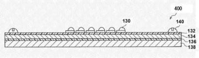
- the semiconductor device includes a semiconductor element and a cured resin sheet disposed on the semiconductor element.
- the semiconductor device may further include other members as necessary.
- As the semiconductor element a commonly used semiconductor element can be used without particular limitation. Specific examples of the semiconductor element include an IGBT (Insulated Gate Bipolar Transistor), a power semiconductor element such as a thyristor, and an LED element.
- IGBT Insulated Gate Bipolar Transistor
- a power semiconductor element such as a thyristor
- LED element LED element
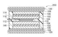
- FIG. 1 shows heat dissipation in which a power semiconductor element 110 is disposed in a housing 103 on a water cooling jacket 120 via a copper plate 104 disposed via a solder layer 112, a cured resin sheet 102, and a grease layer 108.
- 3 is a schematic cross-sectional view showing a configuration example of a power semiconductor device 100 configured with a base 106.
- the periphery of the power semiconductor element 110 is sealed with a sealing resin 146.
- the heating element including the power semiconductor element 110 is in contact with the heat radiating member via the cured resin sheet 102, heat is efficiently radiated.
- the heat dissipation base 106 can be configured using copper, aluminum, or the like having thermal conductivity.
- Examples of the power semiconductor element 110 include an IGBT and a thyristor.
- FIG. 2 is a schematic cross-sectional view showing a configuration example of a power semiconductor device 150 configured by disposing cooling members on both surfaces of the power semiconductor element 110.
- the cooling member disposed on the upper surface of the power semiconductor element 110 includes a two-layer copper plate 104 provided via a solder layer 112. With such a configuration, generation of chip cracks and solder cracks can be more effectively suppressed.
- the copper plate 104 disposed on the side far from the semiconductor element 110 is connected to the water cooling jacket 120 via the resin sheet cured product 102 and the grease layer 108.
- one layer of the copper plate 104 is connected to the water cooling jacket 120 via the resin sheet cured product 102 and the grease layer 108.
- a copper foil, an aluminum foil, or the like may be bonded to the surface of the cured resin sheet 102 on the grease layer 108 side.
- the cured resin sheet 102 and the water cooling jacket 120 are arranged via the grease layer 108, but the cured resin sheet 102 and the water cooling jacket 120 may be arranged so as to be in direct contact with each other.
- FIG. 3 is a schematic cross-sectional view showing a configuration example of a power semiconductor device 200 configured by disposing cooling members on both surfaces of the power semiconductor element 110.
- the cooling members disposed on both surfaces of the power semiconductor element 110 are each configured to include one layer of copper plate 104.
- a copper foil, an aluminum foil, or the like may be bonded to the surface of the cured resin sheet 102 on the grease layer 108 side.
- the cured resin sheet 102 and the water cooling jacket 120 are disposed via the grease layer 108, but the cured resin sheet 102 and the water cooling jacket 120 may be disposed so as to be in direct contact with each other.
- FIG. 4 is a schematic cross-sectional view showing a configuration example of a power semiconductor device 250 configured by arranging cooling members on both surfaces of the power semiconductor element 110.
- the cooling member disposed on the upper surface of the power semiconductor element 110 includes the copper plate 104 provided via the solder layer 112. With such a configuration, generation of chip cracks and solder cracks can be more effectively suppressed. Further, by including the cured resin sheet 102 in the module, it is possible to prevent the influence of sheet cracking, external vibration, and the like, and the reliability is improved.
- FIG. 4 is a schematic cross-sectional view showing a configuration example of a power semiconductor device 250 configured by arranging cooling members on both surfaces of the power semiconductor element 110.
- the cooling member disposed on the upper surface of the power semiconductor element 110 includes the copper plate 104 provided via the solder layer 112.
- the copper plates 104 disposed on the upper surface and the lower surface are connected to the water cooling jacket 120 via the resin sheet cured product 102, the heat dissipation base 106, and the grease layer 108, respectively.
- Examples of the heat dissipation base 106 include copper foil and aluminum foil.
- the power semiconductor element 110 is connected to the external terminal 116 through the wiring member 114.
- the cured resin sheet 102 and the water cooling jacket 120 are disposed via the heat radiation base 106 and the grease layer 108 disposed on the cured resin sheet 102. You may arrange
- FIG. 5 is a schematic cross-sectional view illustrating a configuration example of a power semiconductor device 300 configured by arranging cooling members on both surfaces of the power semiconductor element 110.
- the cooling members disposed on both surfaces of the power semiconductor element 110 are each configured to include one layer of the copper plate 104.
- a copper plate 104 is disposed on one surface of the power semiconductor element 110 with a spacer 101 interposed therebetween. Further, by including the cured resin sheet 102 in the module, it is possible to prevent the influence of sheet cracking, external vibration, and the like, and the reliability is improved.
- the copper plate 104 is connected to the water cooling jacket 120 through the cured resin sheet 102, the heat dissipation base 106 and the grease layer 108.
- the power semiconductor element 110 is connected to an external terminal 116 through a wiring member 114.
- the cured resin sheet 102 and the water cooling jacket 120 are disposed via the heat dissipation base 106 and the grease layer 108 disposed on the cured resin sheet 102. You may arrange
- the power semiconductor element 110 includes a copper plate 104 disposed via a solder layer 112, a cured resin sheet 102, and a heat radiation base 106 disposed on a water cooling jacket 120 via a grease layer 108.
- 2 is a schematic cross-sectional view showing a configuration example of a power semiconductor device 350. Since the heating element including the power semiconductor element 110 is in contact with the heat radiating member via the cured resin sheet 102, heat is efficiently radiated.
- the heat dissipation base 106 can be configured using copper, aluminum, or the like having thermal conductivity.
- the LED device is configured by laminating an LED element, a cured resin sheet, and a substrate in this order.
- the LED device may further include other members as necessary.
- An example of the substrate is an aluminum substrate.
- FIG. 7 is a schematic cross-sectional view showing an example of the configuration of an LED light bar 400 configured using a cured resin sheet.
- the LED light bar 400 includes a housing 138, a grease layer 136, an aluminum substrate 134, a cured resin sheet 132, and an LED chip 130 arranged in this order and fixed with screws 140.
- the LED chip 130 By disposing the LED chip 130 as a heating element on the aluminum substrate 134 through the cured resin sheet 132, it is possible to efficiently dissipate heat.
- FIG. 8 is a schematic cross-sectional view showing a configuration example of the light emitting unit 450 of the LED bulb.
- the light emitting unit 450 of the LED bulb includes a housing 138, a grease layer 136, an aluminum substrate 134, a resin sheet cured product 132, a circuit layer 142, and an LED chip 130 arranged in this order and fixed with screws 140. Composed.
- FIG. 9 is a schematic cross-sectional view showing an example of the overall configuration of the LED bulb 500.
- a housing 138 that constitutes a light emitting portion of the LED bulb is disposed on a sealing resin 146 that encloses a power supply member 148.
- FIG. 10 is a schematic cross-sectional view showing an example of the configuration of the LED substrate 550.
- the LED substrate 550 includes an aluminum substrate 134, a cured resin sheet 132, a circuit layer 142, and an LED chip 130 arranged in this order.
- the LED chip 130 By disposing the LED chip 130 as a heating element on the aluminum substrate 134 via the circuit layer 142 and the cured resin sheet 132, heat can be efficiently radiated.
- AA-18 Aluminum oxide particles, product name: AA-18, manufactured by Sumitomo Chemical Co., Ltd., volume average particle diameter 18 ⁇ m AA-3: aluminum oxide particles, product name: AA-3, manufactured by Sumitomo Chemical Co., Ltd., volume average particle diameter 3 ⁇ m AA-04: aluminum oxide particles, product name: AA-04, manufactured by Sumitomo Chemical Co., Ltd., volume average particle diameter 0.4 ⁇ m ⁇
- HP Boron nitride particles, product name: HP40, manufactured by Mizushima Alloy Iron Co., Ltd., volume average particle diameter 45 ⁇ m
- CRN catechol resorcinol novolak resin, manufactured by Hitachi Chemical Co., Ltd., number average molecular weight 425, phenol compound content 35%
- (Epoxy resin) TN 2,2 ′, 7,7′-tetra (2,3-epoxypropoxy) -1,1′-methylenebisnaphthalene type epoxy resin, product name: HP4710, manufactured by DIC Corporation DN: 1, 6-bis (2,3-epoxypropoxy) naphthalene type epoxy resin, product name: HP-4032D, manufactured by DIC Corporation BP: biphenyl type epoxy resin, model number YL6121H, manufactured by Mitsubishi Chemical Corporation, BIS-A / F: Bisphenol A / F mixed epoxy resin, model number ZX-1059, manufactured by Nippon Steel & Sumikin Chemical Co., Ltd.
- TPM Triphenylmethane type epoxy resin, product name: EPPN-502H, manufactured by Nippon Kayaku Co., Ltd.
- MM 1- ⁇ (3-Methyl-4-oxiranylmethoxy) phenyl ⁇ -4- (4-oxiranylmethoxyphenyl) -1-cyclohexene, synthetic product MM It was prepared by reference to JP 2005-206814.
- TPP Triphenylphosphine (curing accelerator, manufactured by Wako Pure Chemical Industries, Ltd.)
- PET film Product name A31, manufactured by Teijin DuPont Films, Ltd.
- Copper foil Product name CF-T9D-SV, manufactured by Fukuda Metal Foil Powder Co., Ltd., thickness 35 ⁇ m
- the number average molecular weight and the monomer content ratio were quantified by molecular weight measurement by GPC of the obtained product. Moreover, the NMR spectrum of the obtained product was measured, and it confirmed that the catechol resorcinol novolak resin (CRN) had the structural unit represented by general formula (IV). The conditions for GPC measurement and NMR measurement will be described later.
- Example 1 Mixture of aluminum oxide particles (AA-18: AA-3: AA-04; volume-based mixing ratio 2.6: 2.4: 1.0) 57.32 parts and HP 21.12 parts (volume relative to AA-04) A standard mixing ratio of 4.0), 7.38 parts of CRN as a curing agent for epoxy resin, and 29.01 parts of CHN were mixed. After confirming that it was uniform, TN2.16 parts and DN 6.49 parts as epoxy resin and 0.06 parts of TPP were further added and mixed, followed by ball milling for 20 to 40 hours to obtain a resin composition. As a product, a coating solution for forming a resin layer was obtained.
- the resin layer forming coating is about 100 ⁇ m thick on the release treatment surface.
- the working solution was applied using a table coater (manufactured by Tester Sangyo Co., Ltd.) to form a coating layer. It dried for 5 minutes in a 100 degreeC box-type oven, and formed the resin sheet (it is also called A stage sheet) in which the resin layer of the A stage state was formed on PET film.
- the two A stage sheets obtained above were used and stacked so that the resin layers face each other.
- a hot press apparatus hot plate 100 ° C., pressure 10 MPa, treatment time 1 minute
- heat-pressing and bonding a B-stage resin sheet having an average thickness of 177 ⁇ m (also called a B-stage sheet) Got.
- Example 2 A stage state in the same manner as in Example 1 except that 7.13 parts of CRN as a curing agent, 4.39 parts of TN as an epoxy resin, and 4.39 parts of DN were used in Example 1. Resin sheet, B-stage resin sheet, and C-stage resin sheet laminate 2 with copper foil provided on both sides were obtained.
- Example 3 A stage state in the same manner as in Example 1 except that 6.87 parts of CRN as a curing agent, 6.68 parts of TN as an epoxy resin, and 2.22 parts of DN were used in Example 1. Resin sheet, B-stage resin sheet, and C-stage resin sheet laminate 3 having copper foils on both sides were obtained.
- Example 4 A stage state in the same manner as in Example 1 except that 6.77 parts of CRN as a curing agent, 7.62 parts of TN as an epoxy resin, and 1.34 parts of DN were used in Example 1. Resin sheet, B stage resin sheet, and C stage resin sheet cured product 4 with copper foil provided on both sides were obtained.
- Example 5 A stage state in the same manner as in Example 1 except that 6.52 parts of CRN as a curing agent, 2.27 parts of TN as an epoxy resin, and 6.81 parts of BP were used in Example 1. Resin sheet, B-stage resin sheet, and C-stage resin sheet laminate 5 in which copper foil is provided on both surfaces were obtained.
- Example 6 A stage state in the same manner as in Example 1 except that 6.55 parts of CRN as a curing agent, 4.54 parts of TN as an epoxy resin, and 4.53 parts of BP were used in Example 1. Resin sheet, B-stage resin sheet, and C-stage resin sheet laminate 6 in which copper foil is provided on both sides were obtained.
- Example 7 A stage state in the same manner as in Example 1 except that 6.58 parts of CRN as a curing agent, 6.79 parts of TN as an epoxy resin, and 2.27 parts of BP were used in Example 1. Resin sheet, B-stage resin sheet, and C-stage resin sheet cured product 7 in which copper foil is provided on both surfaces were obtained.
- Example 8 In Example 1, 6.74 parts of CRN as a curing agent, 5.72 parts of TN as an epoxy resin, 1.91 parts of BP, 1.34 parts of DN, and 25.92 parts of CHN were used. Except that, in the same manner as in Example 1, a resin sheet laminate cured product 8 in a C stage state in which a resin sheet in an A stage state, a resin sheet in a B stage state, and copper foils were provided on both surfaces was obtained.
- Example 9 In Example 1, 6.59 parts of CRN as a curing agent, 5.77 parts of TN as an epoxy resin, 1.35 parts of BIS-A / F, 1.93 parts of BP, 25.92 of CHN In the same manner as in Example 1 except that it was used, the A-stage resin sheet, the B-stage resin sheet, and the C-stage resin sheet laminate 9 provided with copper foil on both surfaces were respectively obtained. Obtained.
- Example 10 30.84 parts of a mixture of aluminum oxide particles (AA-18: AA-3: AA-04; volume-based mixing ratio 0.84: 0.61: 1) and 66.41 parts of HP (volume-based mixing with AA-04) Ratio 9.5), 16.81 parts of CRN as a curing agent for epoxy resin, and 29.28 parts of CHN were mixed. After confirming that it was uniform, BP 2.40 parts, BIS-A / F 7.60 parts, TN 13.00 parts, and TPP 0.08 parts were further added and mixed as an epoxy resin, and then 20 hours. Ball milling was performed for ⁇ 40 hours to obtain a resin layer forming coating solution as a resin composition.
- a cured resin sheet laminate 10 in a C-stage state in which a resin sheet in an A-stage state, a resin sheet in a B-stage state, and copper foils are provided on both sides is the same as in Example 1. Respectively.
- Example 11 Mixture of aluminum oxide particles (AA-18: AA-3: AA-04; volume-based mixing ratio 0.84: 0.61: 1) 23.97 parts and HP 51.60 parts (volume-based mixing with AA-04) 9.5), 15.10 parts of CRN as a curing agent for epoxy resin, and 31.56 parts of CHN were mixed. After confirming that it was uniform, BP2.10 parts, BIS-A / F6.80 parts, TN11.70 parts, and TPP0.08 parts were further added and mixed as an epoxy resin for 20 hours. Ball milling was performed for ⁇ 40 hours to obtain a resin layer forming coating solution as a resin composition.
- Example 1 Except having used this coating liquid, it carried out similarly to Example 1, and the resin sheet laminated body cured
- ⁇ Comparative Example 1> Mixture of aluminum oxide particles (AA-18: AA-3: AA-04; volume-based mixing ratio 0.84: 0.61: 1.0) 57.32 parts and HP 21.12 parts (volume relative to AA-04) Reference mixing ratio 4.0), 6.50 parts of CRN as a curing agent for epoxy resin, and 34.6 parts of CHN were mixed. After confirming uniformity, BP 9.09 parts as epoxy resin and 0.06 part TPP were further added and mixed, and then ball milling was performed for 20 to 40 hours to form a resin layer as a resin composition. A coating solution was obtained.
- the resin layer forming coating is about 100 ⁇ m thick on the release treatment surface.
- the coating liquid was applied with a table coater (manufactured by Tester Sangyo Co., Ltd.) to form a coating layer. It dried for 5 minutes in a 100 degreeC box-type oven, and formed the resin sheet in which the resin layer of the A stage state was formed on PET film.
- the two A stage sheets obtained above were used and stacked so that the resin layers face each other.
- a hot press apparatus hot plate 100 ° C., pressure 10 MPa, treatment time 1 minute
- heat-pressing and bonding an B-stage resin sheet having an average thickness of 171 ⁇ m (also called a B-stage sheet) Got.
- Comparative Example 2 a resin sheet in the A stage state and a B stage state resin sheet were used in the same manner as in Comparative Example 1, except that 6.61 parts of CRN as a curing agent and 9.04 parts of TN as an epoxy resin were used. C-stage resin sheet laminate cured product C2 having a resin sheet and copper foil provided on both sides was obtained.
- Comparative Example 3 In Comparative Example 1, except that 5.83 parts of CRN as a curing agent and 9.43 parts of MM as an epoxy resin were used, the resin sheet in the A stage state and the B stage state were used in the same manner as in Comparative Example 1. The resin sheet laminated body cured
- Comparative Example 4 In Comparative Example 1, the same procedure as in Comparative Example 1 was used except that 6.69 parts of CRN as a curing agent, 29.01 parts of CHN, and 9.00 parts of TPM as an epoxy resin were used. A resin sheet, a B-stage resin sheet, and a C-stage resin sheet laminate C4 in which copper foil was provided on both surfaces were obtained.
- Comparative Example 5 ⁇ Comparative Example 5> In Comparative Example 1, a comparison was made except that 6.67 parts of CRN as a curing agent, 29.01 parts of CHN, 4.50 parts of TPM as an epoxy resin, and 4.50 parts of BIS-A / F were used. In the same manner as in Example 1, A-stage resin sheet, B-stage resin sheet, and C-stage resin sheet cured product C5 in which copper foils were provided on both surfaces were obtained.
- Comparative Example 6 a comparison was made except that 6.52 parts of CRN as a curing agent, 29.01 parts of CHN, 6.81 parts of TN as an epoxy resin, and 2.27 parts of BIS-A / F were used. In the same manner as in Example 1, A-stage resin sheet, B-stage resin sheet, and C-stage resin sheet cured product C6 in which copper foils were provided on both surfaces were obtained.
- Comparative Example 7 a comparison was made except that 6.55 parts of CRN as a curing agent, 29.01 parts of CHN, 4.53 parts of TN as an epoxy resin, and 4.53 parts of BIS-A / F were used. In the same manner as in Example 1, A stage resin sheet, B stage resin sheet, and C stage resin sheet cured product C7 in which copper foils were provided on both surfaces were obtained.
- Comparative Example 8 In Comparative Example 1, a comparison was made except that 6.58 parts of CRN as a curing agent, 29.01 parts of CHN, 2.27 parts of TN as an epoxy resin, and 6.79 parts of BIS-A / F were used. In the same manner as in Example 1, A-stage resin sheet, B-stage resin sheet, and C-stage resin sheet cured product C8 in which copper foil was provided on both surfaces were obtained.
- GPC [Pump: L6200 Pump (manufactured by Hitachi, Ltd.), Detector: Differential refractive index detector L3300 RI Monitor (manufactured by Hitachi, Ltd.), Column: TSKgel-G5000HXL and TSKgel-G2000HXL (2 in total) ( The number average molecular weight was measured using column temperature: 30 ° C., eluent: tetrahydrofuran, flow rate: 1.0 ml / min, standard substance: polystyrene], both of which were manufactured by Tosoh Corporation in series.
- Thermal conductivity of cured resin sheet laminate The copper foil was removed by etching using a sodium persulfate solution from the cured C-stage resin sheet laminate obtained in the above experiment. This was cut into 10 mm squares, blackened with graphite spray, and the thermal diffusivity was measured using a Nanoflash LFA447 model manufactured by NETZSCH. The measurement conditions were a measurement temperature of 25 ⁇ 1 ° C., a measurement voltage of 270 V, Amplitude 5000, and a pulse width of 0.06 ms. The thermal conductivity was calculated from the product of the thermal diffusivity measured above, the density measured by the Archimedes method, and the specific heat measured by DSC (differential calorimeter).
- the copper foil was removed by etching using a sodium persulfate solution from the cured C-stage resin sheet laminate obtained in the above experiment. This was cut
- the measurement conditions were a temperature rising rate of 3 ° C./minute, a measurement temperature of 30 ° C. to 300 ° C., a frequency of 10 Hz, a span distance of 20 mm, a strain of 1 ⁇ m, and the atmosphere.
- the pulling strength of the copper foil was measured by pulling with 100 type. One sample was measured three times, and the average value was defined as the peel strength. Bonding and curing treatment were performed as follows. After performing a vacuum hot press (hot plate temperature 120 ° C., vacuum degree 1 kPa or less, pressure 10 MPa, treatment time 3 minutes) to bond the copper plate, in a box type oven, 140 ° C. for 2 hours, 165 ° C. for 2 hours, Curing treatment was performed by step curing at 190 ° C. for 2 hours.
- a vacuum hot press hot plate temperature 120 ° C., vacuum degree 1 kPa or less, pressure 10 MPa, treatment time 3 minutes
- the average thickness of the B stage sheet was measured as follows. The B stage sheet was cut into a 100 mm square with the support attached, and the thickness of 9 points was measured with a micrometer IP65 manufactured by Mitutoyo Corporation. The thicknesses of the PET film and the aluminum foil as the support were subtracted on the assumption that they would not change even when the B-stage was formed, and the thicknesses of the resin layers were determined, and the arithmetic average value was used as the average thickness of the B-stage sheet.
- the copper foil was removed by etching using a sodium persulfate solution from the cured C-stage resin sheet laminate obtained above. Thus, a cured resin sheet was obtained.
- the cured resin sheet was cut into a 100 mm square, and this was measured for 9-point thickness with a micrometer IP65 manufactured by Mitutoyo Corporation. The arithmetic average value was defined as the average thickness of the cured resin sheet.
- B stage sheet flexibility The presence or absence of cracking of the sheet when the B stage sheet cut to 50 mm ⁇ 10 mm was pressed against a cylinder having a diameter of 10 mm was determined visually.
- the test temperature was 20 ° C. ⁇ 3 ° C., and the number of tests was 5 times while changing the place.
- the evaluation criteria are as follows. A: Two or more places where cracks are not confirmed. B: The crack is not confirmed at one place or less.
Landscapes
- Engineering & Computer Science (AREA)
- Chemical & Material Sciences (AREA)
- Microelectronics & Electronic Packaging (AREA)
- Computer Hardware Design (AREA)
- Power Engineering (AREA)
- Organic Chemistry (AREA)
- Health & Medical Sciences (AREA)
- Chemical Kinetics & Catalysis (AREA)
- Medicinal Chemistry (AREA)
- Polymers & Plastics (AREA)
- Condensed Matter Physics & Semiconductors (AREA)
- Physics & Mathematics (AREA)
- Manufacturing & Machinery (AREA)
- General Physics & Mathematics (AREA)
- Materials Engineering (AREA)
- Ceramic Engineering (AREA)
- Compositions Of Macromolecular Compounds (AREA)
- Laminated Bodies (AREA)
- Cooling Or The Like Of Semiconductors Or Solid State Devices (AREA)
- Led Device Packages (AREA)
- Manufacture Of Macromolecular Shaped Articles (AREA)
- Adhesive Tapes (AREA)
- Epoxy Resins (AREA)
- Adhesives Or Adhesive Processes (AREA)
Abstract
Description
<1> ナフタレン環を2つ含み前記2つのナフタレン環がアルキレン鎖で連結されている構造を分子中に有する3官能以上の第1のエポキシ樹脂と、メソゲン構造を分子中に有する2官能の第2のエポキシ樹脂と、硬化剤と、を含有する樹脂組成物。
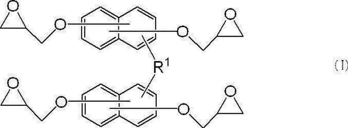
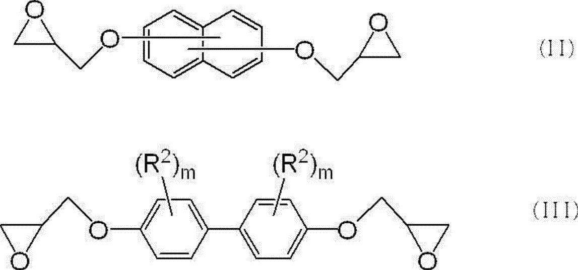

前記樹脂シートに熱を与えて前記樹脂シートを硬化させる工程と、を有する樹脂シート積層体硬化物の製造方法。
前記半導体素子上に配置される<11>に記載の樹脂シート硬化物と、を備える半導体装置。
本明細書において「工程」との語は、独立した工程だけではなく、他の工程と明確に区別できない場合であってもその工程の所期の目的が達成されれば、本用語に含まれる。また「~」を用いて示された数値範囲は、「~」の前後に記載される数値をそれぞれ最小値及び最大値として含む範囲を示す。更に組成物中の各成分の含有量は、組成物中に各成分に該当する物質が複数存在する場合、特に断らない限り、組成物中に存在する当該複数の物質の合計量を意味する。
本明細書において「層」との語は、平面図として観察したときに、全面に形成されている形状の構成に加え、一部に形成されている形状の構成も包含される。
本明細書において「積層」との語は、層を積み重ねることを示し、二以上の層が結合されていてもよく、二以上の層が着脱可能であってもよい。
樹脂組成物は、ナフタレン環を2つ含み前記2つのナフタレン環がアルキレン鎖で連結されている構造を分子中に有する3官能以上の第1のエポキシ樹脂と、メソゲン構造を分子中に有する2官能の第2のエポキシ樹脂と、硬化剤と、を含有する。樹脂組成物は、必要に応じてその他の成分を更に含んでいてもよい。
硬化後において熱伝導性が向上するのは、硬化した樹脂の規則性が従来の樹脂と比較して高まるためである。これには硬化による架橋密度の増加及びエポキシ樹脂の主鎖に含まれるメソゲン構造の結晶性骨格が分子間力によりスタッキングしていることが寄与している。また、このスタッキングと架橋密度の増加はそれぞれが独立して起こる現象ではなく、並列して起こる現象である。これは、特定の第1のエポキシ樹脂及び硬化剤を硬化した硬化物又は特定の第2のエポキシ樹脂と硬化剤とを硬化した硬化物と、第1のエポキシ樹脂、第2のエポキシ樹脂及び硬化剤を含む樹脂組成物を硬化した硬化物とを比較すると明らかであり、特定の第1のエポキシ樹脂及び特定の第2のエポキシ樹脂を混合して用いた樹脂組成物の方が熱伝導性に優れる。一般的にセラミックス、金属の結晶等は異物のない単一な物質の方が結晶の規則性が高まるため、熱伝導率は高くなる。樹脂も同様であり、単一のエポキシ樹脂を用いた場合の方が高い熱伝導率を示すのが通常である。しかし、実際は特定のエポキシ樹脂を混合した方が熱伝導率については高い値を示すと考えられる。
高温での接着性については、本樹脂系では高い架橋密度を狙ったものではなく、一方で、ガラス転移温度は高いので、樹脂組成物の使用温度としてやや高い180℃まで良好なピール強度を示すと考えられる。
樹脂組成物は、エポキシ樹脂として、ナフタレン環を2つ含み前記2つのナフタレン環がアルキレン鎖で連結されている構造を分子中に有する3官能以上の第1のエポキシ樹脂と、メソゲン構造を分子中に有する2官能の第2のエポキシ樹脂と、を含有する。樹脂組成物は、必要に応じて、エポキシ樹脂として、第1のエポキシ樹脂及び第2のエポキシ樹脂以外のその他のエポキシ樹脂を含有してもよい。

ナフタレン環におけるR1の結合する位置は特に限定されるものではなく、1位の位置であっても2位の位置であってもよく、1位の位置が好ましい。R1の結合する位置は、各ナフタレン環において同じ位置であってもよいし、異なる位置であってもよい。
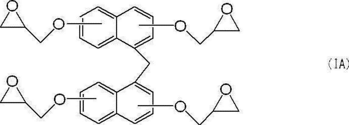
メソゲン構造を有するエポキシ樹脂が特定の温度で硬化した後に良好な熱伝導性を得られることが知られている。なお、メソゲン構造を有するエポキシ樹脂を用いることで、エポキシ樹脂が特定の温度で硬化剤と反応し樹脂硬化物を形成した場合に、樹脂硬化物中にメソゲン構造に由来する規則性のある高次構造を形成することがある。また、高次構造は、樹脂組成物の硬化後にメソゲン構造により分子が配列している状態を意味する。

R2として表されるアルキル基としては、メチル基、エチル基、ブチル基等が挙げられる。
R2として表されるアリール基としては、フェニル基等が挙げられる。
R2として表されるアラルキル基としては、ベンジル基等が挙げられる。
R2で表されるアルキル基、アリール基及びアラルキル基は、必要に応じて置換基を更に有していてもよい。該置換基としては、アルキル基、アリール基、ハロゲン原子、水酸基等を挙げることができる。
R2としては、メチル基、及びエチル基が好ましい。
エポキシ樹脂は、1種のメソゲン構造を含んでいるものであっても、2種のメソゲン構造を含んでいるものであってもよい。
以下に、好適に用いられるメソゲン構造の具体例を示す。なお、メソゲン構造はこれら具体例に限定されるものではない。
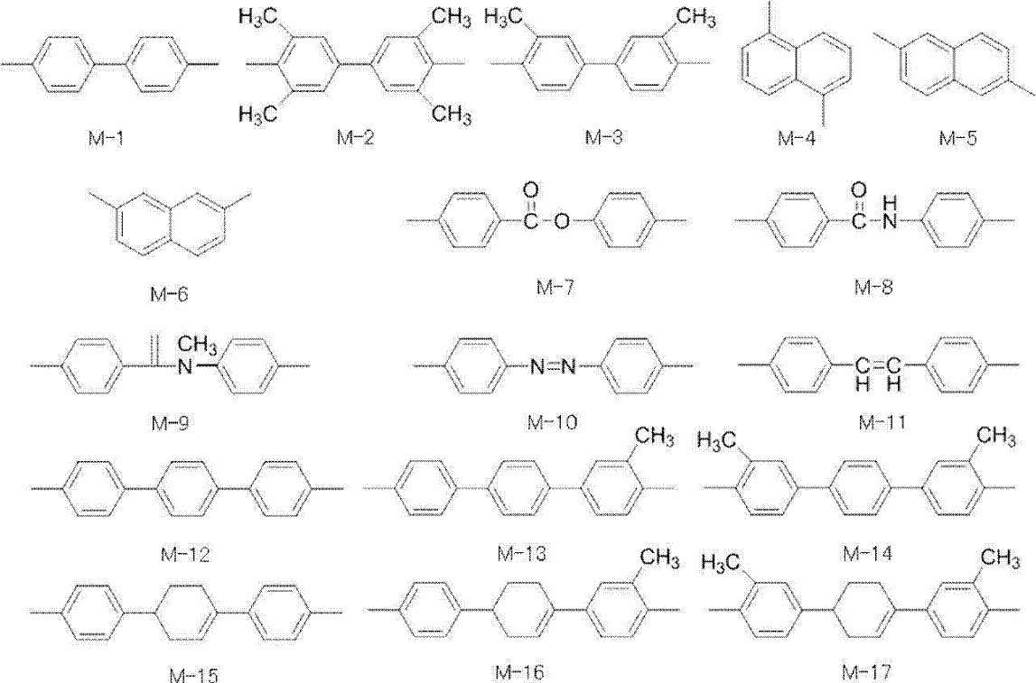
エポキシ樹脂として、一般式(I)で表される化合物と、一般式(II)で表される化合物及び一般式(III)で表される化合物からなる群より選択される少なくとも1種と、を用いると、樹脂組成物中の分子鎖の配向性をより高めることができる傾向にある。その結果、硬化物の熱伝導性及び耐熱性が向上する傾向にある。また、エポキシ樹脂として一般式(I)で表される化合物と、一般式(II)で表される化合物及び一般式(III)で表される化合物からなる群より選択される少なくとも1種とを用い、後述する一般式(IV)で表される構造単位を有するノボラック樹脂を硬化剤として用いることで、特定のエポキシ樹脂との硬化反応による共有結合の形成が密になり、分子鎖の配向性を更に高めることができる。その結果、硬化物の熱伝導性が更に向上する傾向にある。
また、第1のエポキシ樹脂と第2のエポキシ樹脂とを併用することで、メソゲン構造の分子間力とエポキシ樹脂の架橋反応による共有結合形成の相乗効果を働かせることができる。これはどちらの効果に対しても、希釈効果があるためである。つまり、第2のエポキシ樹脂を用いずに第1のエポキシ樹脂のみをエポキシ樹脂として用いると、高架橋密度を達成できる設計になる。しかし、反応途中でエポキシ樹脂の分子鎖が動けなくなり反応停止が起きてしまうことがあり、末端の官能基が余ってしまうことから耐熱特性及び電気特性が低下する恐れがある。逆に、第1のエポキシ樹脂を用いずにメソゲン構造を有する第2のエポキシ樹脂のみをエポキシ樹脂として用いると、エポキシ樹脂の融点が高まり、溶融し難くなる。また、溶融させるために高温にすると、反応が早く起きてしまい、流動不十分な状態で硬化してしまうことから、良好な成形体が得られ難いことがある。また、このようなエポキシ樹脂は粘度が低すぎて、エポキシ樹脂がフィラーと分離することも多い。そのため、エポキシ樹脂が十分に硬化剤と混ざり合わないまま反応が進み、混合が反応が終了してしまうこと、及び、分子間力も十分に働かないままになることがある。また、硬化剤と樹脂の分離も起き易いことから、単体では非常に取り扱い難い。
被着体に十分に濡れないまま硬化反応が進んでしまうと、接着強度も低いものになってしまうことがある。しかし、第1のエポキシ樹脂と第2のエポキシ樹脂とを併用することで、第1のエポキシ樹脂が第2のエポキシ樹脂を希釈する効果及び、第2のエポキシ樹脂が第1のエポキシ樹脂を希釈する効果が相互に働き、樹脂組成物の硬化後における優れた高温での接着性及び熱伝導性を実現可能となる傾向にある。
樹脂組成物においては、第1のエポキシ樹脂と第2のエポキシ樹脂との質量基準の含有比(第1のエポキシ樹脂:第2のエポキシ樹脂)が、25:75~85:15であることが好ましく、30:70~80:20であることがより好ましく、35:65~75:25であることが更に好ましい。
また、第1のエポキシ樹脂として一般式(I)で表される化合物を用い、第2のエポキシ樹脂として一般式(III)で表される化合物を用いた場合の第1のエポキシ樹脂と第2のエポキシ樹脂との質量基準の含有比(第1のエポキシ樹脂:第2のエポキシ樹脂)は、25:75~85:15であってもよく、35:65~75:25であってもよく、40:60~65:35であってもよい。
樹脂組成物は、硬化剤を含有する。使用可能な硬化剤は、エポキシ樹脂と硬化反応が可能な化合物であれば特に制限されるものではない。硬化剤の具体例としては、ノボラック樹脂、芳香族アミン硬化剤、脂肪族アミン硬化剤、メルカプタン硬化剤、酸無水物硬化剤等の重付加型硬化剤などを挙げることができる。また、これらの硬化剤に加えて、イミダゾール、トリフェニルホスフィン、これらの化合物に側鎖を導入した誘導体等の硬化促進剤を併用してもよい。
これらの中でも、ノボラック樹脂が好ましく、下記一般式(IV)で表される構造単位を有するノボラック樹脂(以下、特定ノボラック樹脂と称することがある)がより好ましい。
特定ノボラック樹脂は、硬化剤として作用し、上述のエポキシ樹脂と反応して樹脂硬化物を形成し、絶縁性、接着性及び熱伝導性を発現する。上述の特定のエポキシ樹脂と特定ノボラック樹脂とを含むことで、硬化前にはより優れた柔軟性を示し、硬化後にはより優れた熱伝導性及び高温接着性を示すことができる。
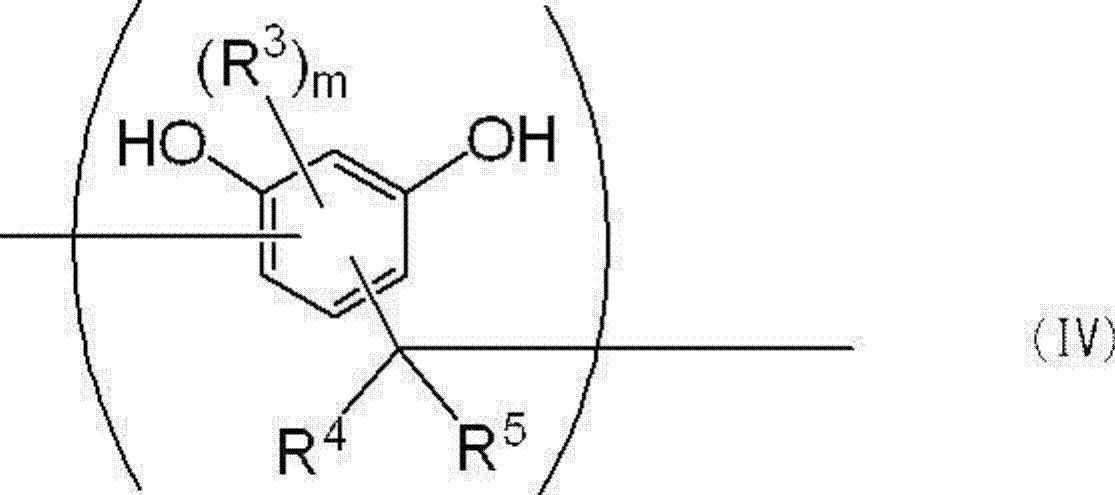


nは1~7の数であり、一般式(IV)で表される構造単位の繰り返し数である。特定ノボラック樹脂が単一の化合物である場合、nは整数である。特定ノボラック樹脂が複数の分子種から構成される場合、nは一般式(IV)で表される構造単位の含有数の平均値であり、有理数となる。特定ノボラック樹脂が一般式(IV)で表される構造単位を有する複数種の化合物を含む場合、nは、接着性と熱伝導性の観点から、その平均値が1.7~6.5であることが好ましく、2.4~6.1であることがより好ましい。

特定ノボラック樹脂の数平均分子量は、ゲルパーミエーションクロマトグラフィー法(GPC)を用いて定法に従い測定する。
特定ノボラック樹脂に含まれるフェノール化合物の含有率としては、5質量%~60質量%が好ましく、10質量%~55質量%がより好ましく、15質量%~50質量%が更に好ましい。
樹脂組成物は、必要に応じてフィラーを含有してもよい。フィラーの材質としては、絶縁性を有する無機化合物粒子であれば特に制限はなく、高い熱伝導性と体積抵抗率を有するものであることが好ましい。具体例としては、酸化アルミニウム、酸化アルミニウムの水和物、酸化マグネシウム、窒化ホウ素、窒化アルミニウム、窒化ケイ素、タルク、マイカ、水酸化アルミニウム、硫酸バリウム等の無機化合物粒子を挙げることができる。中でも、熱伝導性と絶縁性の観点から、酸化アルミニウム、窒化ホウ素、窒化アルミニウム及び水酸化アルミニウムからなる群より選ばれる少なくとも1種の無機化合物粒子であることが好ましい。フィラーは、1種単独で用いても、2種以上を組み合わせて用いてもよい。
撮影した三次元像から、フィラー組織を二値化により抽出して、粒子が球であると仮定して、体積平均粒子径を算出可能である。
また、フィラーに含まれる体積平均粒子径が1μm以下の無機粒子の含有率は、熱伝導性の観点から、フィラーの総体積を100体積%とした場合、0.1体積%~30体積%であることが好ましく、接着性の観点から1体積%~20体積%であることがより好ましい。
樹脂組成物中のフィラーの含有率は、熱伝導性と接着性の観点から、樹脂組成物の全固形分体積中30体積%~90体積%であることが好ましく、熱伝導性の観点から、40体積%~80体積%であることがより好ましい。なお、樹脂組成物の全固形分体積とは、樹脂組成物を構成する成分のうち非揮発性成分の総体積を意味する。
樹脂組成物は、上記成分に加えて必要に応じてその他の成分を含むことができる。その他の成分としては、有機溶剤、硬化促進剤、分散剤等を挙げることができる。
樹脂組成物の製造方法としては、通常行なわれる樹脂組成物の製造方法を特に制限なく用いることができる。エポキシ樹脂及び硬化剤並びに必要に応じて用いられるフィラー、硬化促進剤等を混合する方法としては、通常の撹拌機、らいかい機、三本ロール、ボールミル等の分散機を適宜組み合わせて行うことができる。また、適当な有機溶剤を添加して、分散又は溶解を行うことができる。
なお、樹脂組成物を組成物セットとして用いる場合、第1組成物にはエポキシ樹脂及び硬化剤が含まれ必要に応じて用いられる硬化促進剤が含まれていないことが好ましく、第2組成物には必要に応じて用いられる硬化促進剤が含まれエポキシ樹脂及び硬化剤が含まれていないことが好ましい。また、必要に応じて用いられるフィラー等の成分は、第1組成物及び第2組成物のいずれか一方に含有されていてもよいし、第1組成物及び第2組成物の両方に含有されていてもよい。
樹脂シートは、樹脂組成物を含み、平均厚さが40μm~250μmとされたものである。樹脂シートが樹脂組成物から形成されることで、硬化前の保存安定性と硬化後の熱伝導性に優れる。樹脂組成物の詳細については既述の通りである。
また、樹脂シートは、樹脂組成物を含む第1の樹脂層と、第1の樹脂層上に積層される樹脂組成物を含む第2の樹脂層とを有する積層体であり、前記積層体の一方の面上に金属箔を更に有し、他方の面上にプラスチックフィルム等の保護フィルムを更に有することが好ましい。すなわち樹脂シートは更に金属箔及びプラスチックフィルム等の保護フィルムを有し、金属箔、第1の樹脂層、第2の樹脂層及びプラスチックフィルム等の保護フィルムの順に設けられてなることが好ましい。これによりボイドの穴埋め効果が得られ、絶縁耐圧がより向上する傾向がある。
樹脂シートの製造方法は、樹脂組成物を用いて、平均厚さが40μm~250μmのシート状の樹脂層を形成可能な方法であれば特に制限されず、通常用いられるシート製造方法から適宜選択することができる。樹脂シートの製造方法として具体的には、有機溶剤を含む樹脂組成物を、支持体上に、所望の平均厚さとなるように付与して樹脂組成物層を形成し、形成された樹脂組成物層を乾燥処理して有機溶剤の少なくとも一部を除去して樹脂層を形成する方法等を挙げることができる。
50mm×10mmに切断したBステージシートを直径10mmの円柱に押し付けた際のシートの割れの有無を目視で判定する。試験温度を20℃±3℃とし、試験は一つのサンプルに対して場所を変えながら、5箇所で測定する。5箇所のうち、割れが確認されないのが2箇所以上の場合、直径10mmの円柱の外周面に沿うように折り曲げが可能と判断する。
樹脂シート硬化物は、樹脂シートの熱処理物である。すなわち樹脂シート硬化物は、樹脂シートを熱処理することで樹脂シートを構成する樹脂組成物を硬化させて形成される。従って、樹脂シート硬化物は、第1のエポキシ樹脂、第2のエポキシ樹脂及び硬化剤に由来する構造単位を含有する樹脂硬化物と必要に応じてフィラー等のその他の成分とを含有する。
すなわち、分子中にメソゲン構造を有するエポキシ樹脂と特定ノボラック樹脂とを用いて樹脂硬化物を形成することで、樹脂硬化物中に規則性の高い高次構造を形成することができる。しかし、特定の温度範囲でなければ、規則性の高い構造が得られない場合があることから、所望の熱伝導率が得られないことがある。上述の樹脂シート硬化物を製造する際の熱処理条件によれば、分子中にメソゲン構造を有するエポキシ樹脂と特定ノボラック樹脂とを用いて樹脂硬化物を形成する場合に、規則性の高い構造の硬化物が得られやすく、熱伝導率を向上させやすい傾向にある。
樹脂シート積層体は、樹脂シートと、前記樹脂シートの少なくとも一方の面上に配置される金属板又は放熱板とを有する。樹脂シート積層体を構成する樹脂シートの詳細については既述の通りである。また金属板又は放熱板としては、銅板、アルミ板、セラミックス板等が挙げられる。なお、金属板又は放熱板の厚さは特に限定されず、目的等に応じて適宜選択することができる。また、金属板又は放熱板として、銅箔、アルミニウム箔等の金属箔を使用してもよい。
樹脂シート積層体は、前記樹脂シートの一方の面上に金属板又は放熱板を有し、前記金属板又は放熱板の配置される面とは反対の面に金属箔を有していてもよい。
樹脂シート積層体硬化物は、前記樹脂シート積層体の熱処理物である。樹脂シート積層体硬化物の製造方法は、前記樹脂シートの少なくとも一方の面上に、金属板又は放熱板を配置する工程と、前記樹脂シートに熱を与えて前記樹脂シートを硬化させる工程とを有し、必要に応じてその他の工程を含んで構成される。
半導体装置は、半導体素子と、前記半導体素子上に配置される樹脂シート硬化物とを備える。前記半導体装置は必要に応じてその他の部材を更に有していてもよい。前記半導体素子としては、通常用いられる半導体素子を特に制限なく用いることができる。半導体素子として具体的には、IGBT(Insulated Gate Bipolar Transistor)、サイリスタ等のパワー半導体素子、LED素子などを挙げることができる。以下、図面を参照しながら半導体装置の構成例について説明する。
図1は、ハウジング103内に、パワー半導体素子110が、はんだ層112を介して配置される銅板104と、樹脂シート硬化物102と、グリース層108を介して水冷ジャケット120上に配置される放熱ベース106とで構成されたパワー半導体装置100の構成例を示す模式断面図である。パワー半導体素子110の周囲は、封止樹脂146で封止されている。パワー半導体素子110を含む発熱体が、樹脂シート硬化物102を介して放熱部材と接触していることで、効率よく放熱が行なわれる。なお、放熱ベース106は、熱伝導性を有する銅、アルミニウム等を用いて構成することができる。またパワー半導体素子110としては、IGBT、サイリスタ等を挙げることができる。
LED装置は、LED素子と、樹脂シート硬化物と、基板とがこの順に積層されて構成される。LED装置は、必要に応じてその他の部材を更に有していてもよい。前記基板としては、アルミニウム基板を挙げることができる。
図7は、樹脂シート硬化物を用いて構成されるLEDライトバー400の構成の一例を示す模式断面図である。LEDライトバー400は、ハウジング138と、グリース層136と、アルミニウム基板134と、樹脂シート硬化物132と、LEDチップ130とがこの順に配置され、ビス140で固定されて構成される。発熱体であるLEDチップ130が樹脂シート硬化物132を介してアルミニウム基板134上に配置されることで、効率よく放熱することができる。
(フィラー)
・AA-18:酸化アルミニウム粒子、製品名:AA-18、住友化学(株)製、体積平均粒子径18μm
・AA-3:酸化アルミニウム粒子、製品名:AA-3、住友化学(株)製、体積平均粒子径3μm
・AA-04:酸化アルミニウム粒子、製品名:AA-04、住友化学(株)製、体積平均粒子径0.4μm
・HP:窒化ホウ素粒子、製品名:HP40、水島合金鉄(株)製、体積平均粒子径45μm
・CRN:カテコールレゾルシノールノボラック樹脂、日立化成(株)製、数平均分子量425、フェノール化合物の含有率35%
・TN:2,2’,7,7’-テトラ(2,3-エポキシプロポキシ)-1,1’-メチレンビスナフタレン型エポキシ樹脂、製品名:HP4710、DIC(株)製
・DN:1,6-ビス(2,3-エポキシプロポキシ)ナフタレン型エポキシ樹脂、製品名:HP-4032D、DIC(株)製
・BP:ビフェニル型エポキシ樹脂、型番YL6121H、三菱化学(株)製
・BIS-A/F:ビスフェノールA/F混合型エポキシ樹脂、型番ZX-1059、新日鉄住金化学(株)製
・TPM:トリフェニルメタン型エポキシ樹脂、製品名:EPPN-502H、日本化薬(株)製
・MM:1-{(3-メチル-4-オキシラニルメトキシ)フェニル}-4-(4-オキシラニルメトキシフェニル)-1-シクロヘキセン、合成品
尚、MMは、特開2005-206814号公報を参考にして調製した。
・TPP:トリフェニルホスフィン(硬化促進剤、和光純薬工業(株)製)
・CHN:シクロヘキサノン(和光純薬工業(株)製、1級)
・PETフィルム:製品名A31、帝人デュポンフィルム(株)製
・銅箔:製品名CF-T9D-SV、福田金属箔粉工業(株)製、厚さ35μm
(ノボラック樹脂の合成)
窒素雰囲気下でセパラブルフラスコに、フェノール化合物のモノマーとしてレゾルシノール105g及びカテコール5g、触媒としてシュウ酸0.11g(対モノマー比 0.1%)、並びに溶剤としてメタノール15gをそれぞれ量り取った後、内容物を撹拌し、40℃以下になるように油浴で冷却しながらホルマリン30gを加えた。2時間撹拌した後、油浴の温度を100℃にして、加温しながら水及びメタノールを減圧留去した。水及びメタノールが留出しなくなったことを確認した後、CHNをノボラック樹脂の含有率が35%となるように加えて、カテコールレゾルシノールノボラック樹脂(CRN)溶液を得た。
酸化アルミニウム粒子の混合物(AA-18:AA-3:AA-04;体積基準混合比2.6:2.4:1.0)57.32部と、HP21.12部(AA-04に対する体積基準混合比4.0)と、エポキシ樹脂の硬化剤としてCRN7.38部と、CHN29.01部とを混合した。均一になったことを確認した後に、エポキシ樹脂としてTN2.16部及びDN6.49部と、TPP0.06部とを更に加えて混合した後、20時間~40時間ボールミル粉砕を行って、樹脂組成物として樹脂層形成用塗工液を得た。
上記で得られたBステージシートの両面からPETフィルムを剥離し、その両面に35μm厚の銅箔(福田金属箔粉工業(株)製、CF-T9D-SV)をそれぞれ重ねた後、プレス処理を行った。プレス処理条件は熱板温度150℃、真空度10kPa以下、圧力10MPa、処理時間3分とした。更にボックス型オーブン中、140℃で2時間、165℃で2時間、190℃で2時間、順次加熱処理することにより、両面に銅箔が設けられたCステージ状態の樹脂シート積層体硬化物1を得た。
実施例1において、硬化剤であるCRNを7.13部、エポキシ樹脂であるTNを4.39部、DNを4.39部、用いたこと以外は実施例1と同様にして、Aステージ状態の樹脂シート、Bステージ状態の樹脂シート及び両面に銅箔が設けられたCステージ状態の樹脂シート積層体硬化物2をそれぞれ得た。
実施例1において、硬化剤であるCRNを6.87部、エポキシ樹脂であるTNを6.68部、DNを2.22部、用いたこと以外は実施例1と同様にして、Aステージ状態の樹脂シート、Bステージ状態の樹脂シート及び両面に銅箔が設けられたCステージ状態の樹脂シート積層体硬化物3をそれぞれ得た。
実施例1において、硬化剤であるCRNを6.77部、エポキシ樹脂であるTNを7.62部、DNを1.34部、用いたこと以外は実施例1と同様にして、Aステージ状態の樹脂シート、Bステージ状態の樹脂シート及び両面に銅箔が設けられたCステージ状態の樹脂シート積層体硬化物4をそれぞれ得た。
実施例1において、硬化剤であるCRNを6.52部、エポキシ樹脂であるTNを2.27部、BPを6.81部、用いたこと以外は実施例1と同様にして、Aステージ状態の樹脂シート、Bステージ状態の樹脂シート及び両面に銅箔が設けられたCステージ状態の樹脂シート積層体硬化物5をそれぞれ得た。
実施例1において、硬化剤であるCRNを6.55部、エポキシ樹脂であるTNを4.54部、BPを4.53部、用いたこと以外は実施例1と同様にして、Aステージ状態の樹脂シート、Bステージ状態の樹脂シート及び両面に銅箔が設けられたCステージ状態の樹脂シート積層体硬化物6をそれぞれ得た。
実施例1において、硬化剤であるCRNを6.58部、エポキシ樹脂であるTNを6.79部、BPを2.27部、用いたこと以外は実施例1と同様にして、Aステージ状態の樹脂シート、Bステージ状態の樹脂シート及び両面に銅箔が設けられたCステージ状態の樹脂シート積層体硬化物7をそれぞれ得た。
実施例1において、硬化剤であるCRNを6.74部、エポキシ樹脂であるTNを5.72部、BPを1.91部、DNを1.34部、CHNを25.92部、用いたこと以外は実施例1と同様にして、Aステージ状態の樹脂シート、Bステージ状態の樹脂シート及び両面に銅箔が設けられたCステージ状態の樹脂シート積層体硬化物8をそれぞれ得た。
実施例1において、硬化剤であるCRNを6.59部、エポキシ樹脂であるTNを5.77部、BIS-A/Fを1.35部、BPを1.93部、CHNを25.92部、用いたこと以外は実施例1と同様にして、Aステージ状態の樹脂シート、Bステージ状態の樹脂シート及び両面に銅箔が設けられたCステージ状態の樹脂シート積層体硬化物9をそれぞれ得た。
酸化アルミニウム粒子の混合物(AA-18:AA-3:AA-04;体積基準混合比0.84:0.61:1)30.84部と、HP66.41部(AA-04に対する体積基準混合比9.5)と、エポキシ樹脂の硬化剤としてCRN16.81部と、CHN29.28部とを混合した。均一になったことを確認した後に、エポキシ樹脂としてBP2.40部と、BIS-A/F7.60部と、TN13.00部と、TPP0.08部とを更に加えて混合した後に、20時間~40時間ボールミル粉砕を行って、樹脂組成物として樹脂層形成用塗工液を得た。この塗工液を用いた以外は実施例1と同様にして、Aステージ状態の樹脂シート、Bステージ状態の樹脂シート及び両面に銅箔が設けられたCステージ状態の樹脂シート積層体硬化物10をそれぞれ得た。
酸化アルミニウム粒子の混合物(AA-18:AA-3:AA-04;体積基準混合比0.84:0.61:1)23.97部と、HP51.60部(AA-04に対する体積基準混合比9.5)と、エポキシ樹脂の硬化剤としてCRN15.10部と、CHN31.56部とを混合した。均一になったことを確認した後に、エポキシ樹脂としてBP2.10部と、BIS-A/F6.80部と、TN11.70部と、TPP0.08部とを更に加えて混合した後に、20時間~40時間ボールミル粉砕を行って、樹脂組成物として樹脂層形成用塗工液を得た。この塗工液を用いた以外は実施例1と同様にして、Aステージ状態の樹脂シート、Bステージ状態の樹脂シート及び両面に銅箔が設けられたCステージ状態の樹脂シート積層体硬化物11をそれぞれ得た。
酸化アルミニウム粒子の混合物(AA-18:AA-3:AA-04;体積基準混合比0.84:0.61:1.0)57.32部と、HP21.12部(AA-04に対する体積基準混合比4.0)と、エポキシ樹脂の硬化剤としてCRN6.50部と、CHN34.6部とを混合した。均一になったことを確認した後に、エポキシ樹脂としてBP9.09部と、TPP0.06部とを更に加えて混合した後、20時間~40時間ボールミル粉砕を行って、樹脂組成物として樹脂層形成用塗工液を得た。
上記で得られたBステージシートの両面からPETフィルムを剥離し、その両面に35μm厚の銅箔(福田金属箔粉工業(株)製、CF-T9D-SV)をそれぞれ重ねた後、プレス処理を行った。プレス処理条件は熱板温度150℃、真空度10kPa以下、圧力10MPa、処理時間3分とした。更にボックス型オーブン中、140℃で2時間、165℃で2時間、190℃で2時間、順次加熱処理することにより、両面に銅箔が設けられたCステージ状態の樹脂シート積層体硬化物C1を得た。
比較例1において、硬化剤であるCRNを6.61部、エポキシ樹脂であるTNを9.04部用いたこと以外は比較例1と同様にして、Aステージ状態の樹脂シート、Bステージ状態の樹脂シート及び両面に銅箔が設けられたCステージ状態の樹脂シート積層体硬化物C2をそれぞれ得た。
比較例1において、硬化剤であるCRNを5.83部、エポキシ樹脂であるMMを9.43部用いたこと以外は比較例1と同様にして、Aステージ状態の樹脂シート、Bステージ状態の樹脂シート及び両面に銅箔が設けられたCステージ状態の樹脂シート積層体硬化物C3をそれぞれ得た。
比較例1において、硬化剤であるCRNを6.69部、CHNを29.01部、エポキシ樹脂であるTPMを9.00部用いたこと以外は比較例1と同様にして、Aステージ状態の樹脂シート、Bステージ状態の樹脂シート及び両面に銅箔が設けられたCステージ状態の樹脂シート積層体硬化物C4をそれぞれ得た。
比較例1において、硬化剤であるCRNを6.67部、CHNを29.01部、エポキシ樹脂であるTPMを4.50部、BIS-A/Fを4.50部用いたこと以外は比較例1と同様にして、Aステージ状態の樹脂シート、Bステージ状態の樹脂シート及び両面に銅箔が設けられたCステージ状態の樹脂シート積層体硬化物C5をそれぞれ得た。
比較例1において、硬化剤であるCRNを6.52部、CHNを29.01部、エポキシ樹脂であるTNを6.81部、BIS-A/Fを2.27部用いたこと以外は比較例1と同様にして、Aステージ状態の樹脂シート、Bステージ状態の樹脂シート及び両面に銅箔が設けられたCステージ状態の樹脂シート積層体硬化物C6をそれぞれ得た。
比較例1において、硬化剤であるCRNを6.55部、CHNを29.01部、エポキシ樹脂であるTNを4.53部、BIS-A/Fを4.53部用いたこと以外は比較例1と同様にして、Aステージ状態の樹脂シート、Bステージ状態の樹脂シート及び両面に銅箔が設けられたCステージ状態の樹脂シート積層体硬化物C7をそれぞれ得た。
比較例1において、硬化剤であるCRNを6.58部、CHNを29.01部、エポキシ樹脂であるTNを2.27部、BIS-A/Fを6.79部用いたこと以外は比較例1と同様にして、Aステージ状態の樹脂シート、Bステージ状態の樹脂シート及び両面に銅箔が設けられたCステージ状態の樹脂シート積層体硬化物C8をそれぞれ得た。
上記で得られたCRN、Aステージ状態の樹脂シート、Bステージ状態の樹脂シート及びCステージ状態の樹脂シート積層体硬化物について、以下の評価を行った。評価結果を表1~表2に示す。なお、表1~表2の樹脂組成物における数値の単位は質量部である。
上記合成例で得られたCRNをテトラヒドロフラン(液体クロマトグラフ用)に溶解し、PTFE製フィルタ(クラボウ社製、HPLC前処理用、クロマトディスク、型番:13N、孔径:0.45μm)を通して不溶分を除去した。GPC〔ポンプ:L6200 Pump((株)日立製作所製)、検出器:示差屈折率検出器L3300 RI Monitor((株)日立製作所製)、カラム:TSKgel-G5000HXLとTSKgel-G2000HXL(計2本)(共に東ソー(株)製)を直列に繋いだ、カラム温度:30℃、溶離液:テトラヒドロフラン、流速:1.0ml/分、標準物質:ポリスチレン〕を用い、数平均分子量を測定した。
上記の合成例で得られたCRNを重ジメチルスルホキシド(DMSO-d6)に溶解し、プロトン核磁気共鳴法(1H-NMR)(BRUKER社、AV-300(300MHz))を用いて、1H-NMRスペクトルを測定した。化学シフトの基準は、内部基準物質であるテトラメチルシランを0ppmとした。
上記の実験で得られたCステージ状態の樹脂シート積層体硬化物から、過硫酸ナトリウム溶液を用いて銅箔をエッチング除去した。これを10mm角に切断し、グラファイトスプレーにより黒化処理し、熱拡散率をNETZSCH社製Nanoflash LFA447型を用いて測定した。
測定条件は、測定温度25±1℃、測定電圧270V、Amplitude5000及びパルス幅0.06msとした。
上記で測定された熱拡散率と、アルキメデス法で測定した密度、DSC(示差熱量計)により測定した比熱の積から熱伝導率を算出した。
上記の実験で得られたCステージ状態の樹脂シート積層体硬化物から、過硫酸ナトリウム溶液を用いて銅箔をエッチング除去した。これを30mm×5mmに切断し、(株)ユービーエム製、RHEO SPECTOLERを用いて貯蔵弾性率及び損失弾性率の温度依存性を測定した。損失弾性率にて、貯蔵弾性率を除した値でtanδを定義し、このピークに達した時の温度をガラス転移温度とした。測定条件は昇温速度3℃/分、測定温度30℃~300℃、周波数10Hz、スパン間距離20mm、歪み1μm、大気中とした。
100mm×100mm×0.2mmのBステージシートの両面からPETフィルムを剥がした後、その両面に100mm×100mm×0.035mmの銅箔を重ねてプレスにて貼り合わせ、硬化処理してCステージ化した。これを100mm×25mmに切断し、片面をテープで保護し、エッチング処理にて反対側の銅箔を除去し、100mm×10mmの銅パターンを作製した。この銅パターンを試験速度50mm/分、測定温度23℃(ピール強度)、150℃(150℃ピール強度)及び180℃(180℃ピール強度)の条件にて、(株)島津製作所製、AGC-100型で引っ張ることで、銅箔の引き剥がし強度を測定した。一つのサンプルにつき、3回測定を行い、平均値をピール強度とした。
なお、貼り合わせ及び硬化処理は以下のようにして行った。真空熱プレス(熱板温度120℃、真空度1kPa以下、圧力10MPa、処理時間3分)を行って銅板を接着した後、ボックス型オーブン中で、140℃で2時間、165℃で2時間、190℃で2時間のステップキュアにより硬化処理を行った。
Bステージシートの平均厚さを以下のようにして測定した。Bステージシートを支持体がついたまま100mm角に切り出し、(株)ミツトヨ製、マイクロメータ IP65にて9点の厚さを測定した。支持体であるPETフィルム及びアルミ箔の厚さは、Bステージ化しても変わらないとして差し引いて、樹脂層の厚さをそれぞれ求め、その算術平均値をBステージシートのそれぞれの平均厚さとした。
上記で得られたCステージ状態の樹脂シート積層体硬化物から、過硫酸ナトリウム溶液を用いて銅箔をエッチング除去した。以上により、樹脂シート硬化物を得た。樹脂シート硬化物を100mm角に切り出し、これを(株)ミツトヨ製、マイクロメータ IP65にて、9点厚さを測定し、その算術平均値を樹脂シート硬化物の平均厚さとした
50mm×10mmに切断したBステージシートを直径10mmの円柱に押し付けた際のシートの割れの有無を目視で判定し、柔軟性とした。試験温度を20℃±3℃とし、試験数は場所を変えながら5回行うこととした。評価基準は以下の通りである。
A:割れが確認されないのが2箇所以上。
B:割れが確認されないのが1箇所以下。
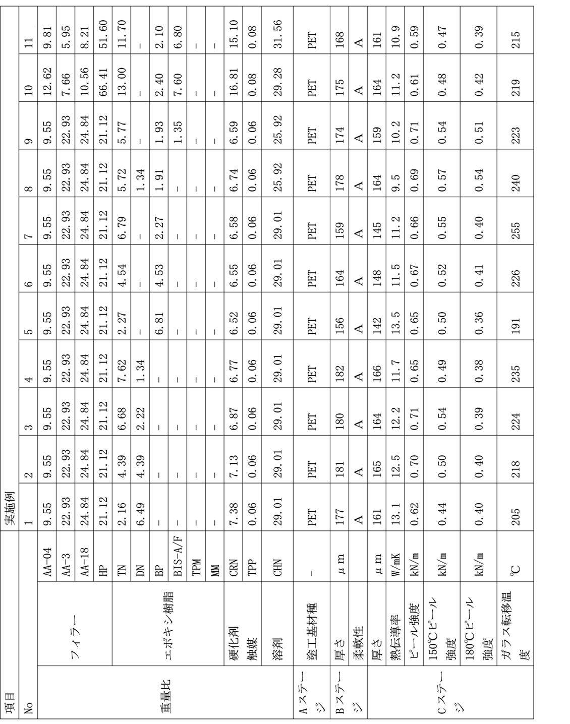
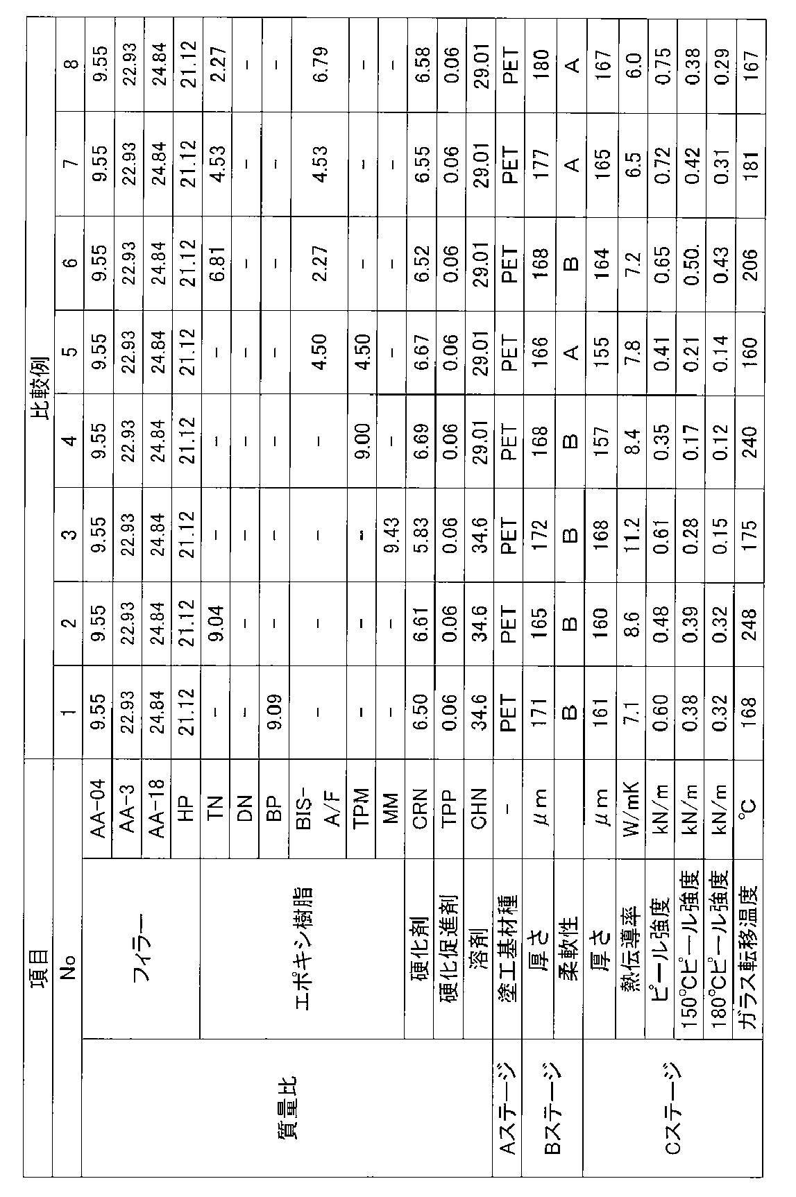
表1及び表2から、一般式(I)に示すエポキシ樹脂と一般式(II)に示すエポキシ樹脂及び一般式(III)に示すエポキシ樹脂からなる群より選択される少なくとも一種と特定ノボラック樹脂とを含有する樹脂組成物並びにこの樹脂組成物から形成されたBステージ状態の樹脂シート及びその硬化物であるCステージ状態の樹脂シート硬化物は、それぞれ優れた熱伝導性と接着性を併せ持つことがわかる。
尚、日本出願2014-058833の開示はその全体が参照により本明細書に取り込まれる。また、本明細書に記載された全ての文献、特許出願、及び技術規格は、個々の文献、特許出願、及び技術規格が参照により取り込まれることが具体的かつ個々に記された場合と同程度に、本明細書中に参照により取り込まれる。
Claims (17)
- ナフタレン環を2つ含み前記2つのナフタレン環がアルキレン鎖で連結されている構造を分子中に有する3官能以上の第1のエポキシ樹脂と、メソゲン構造を分子中に有する2官能の第2のエポキシ樹脂と、硬化剤と、を含有する樹脂組成物。
- 前記第1のエポキシ樹脂が、下記一般式(I)で表される化合物を含む請求項1に記載の樹脂組成物。

(一般式(I)において、R1は、炭素数が1~7のアルキレン基を表す。) - 前記第2のエポキシ樹脂が、下記一般式(II)で表される化合物及び下記一般式(III)で表される化合物からなる群より選択される少なくとも1種を含む請求項1又は請求項2に記載の樹脂組成物。

(一般式(III)において、R2は、各々独立して、アルキル基、アリール基又はアラルキル基を表す。mは、各々独立して、0~2の整数を表す。) - 前記第1のエポキシ樹脂と前記第2のエポキシ樹脂との質量基準の含有比(第1のエポキシ樹脂:第2のエポキシ樹脂)が、25:75~85:15である請求項1~請求項3のいずれか1項に記載の樹脂組成物。
- 前記硬化剤が、下記一般式(IV)で表される構造単位を有するノボラック樹脂を含む請求項1~請求項4のいずれか1項に記載の樹脂組成物。

(一般式(IV)において、R3は、各々独立して、アルキル基、アリール基又はアラルキル基を表す。R4及びR5は、各々独立して、水素原子、アルキル基、アリール基又はアラルキル基を表す。mは0~2の整数を表す。) - 体積平均粒子径が20μm~80μmの窒化ホウ素粒子と、体積平均粒子径が1μm以下の無機粒子とをフィラーとして更に含有する請求項1~請求項5のいずれか1項に記載の樹脂組成物。
- 請求項1~請求項6のいずれか1項に記載の樹脂組成物を含み、平均厚さが40μm~250μmである樹脂シート。
- Bステージ状態において、直径10mmの円柱の外周面に沿うように折り曲げが可能な請求項7に記載の樹脂シート。
- 請求項1~請求項6のいずれか1項に記載の樹脂組成物を含む第1の樹脂層と、前記第1の樹脂層上に積層される請求項1~請求項6のいずれか1項に記載の樹脂組成物を含む第2の樹脂層と、を有する請求項7又は請求項8に記載の樹脂シート。
- 一方の面上に金属箔を有し、前記金属箔を有する面とは反対の面上にプラスチックフィルムを有する請求項7~請求項9のいずれか1項に記載の樹脂シート。
- 請求項7~請求項10のいずれか1項に記載の樹脂シートの熱処理物である樹脂シート硬化物。
- 請求項7~請求項9のいずれか1項に記載の樹脂シートと、前記樹脂シートの少なくとも一方の面上に配置される金属板又は放熱板と、を有する樹脂シート積層体。
- 前記樹脂シートの前記金属板又は放熱板の配置される面とは反対の面に被着体を更に有する請求項12に記載の樹脂シート積層体。
- 請求項12又は請求項13に記載の樹脂シート積層体の熱処理物である樹脂シート積層体硬化物。
- 請求項7~請求項9のいずれか1項に記載の樹脂シートの少なくとも一方の面上に、金属板又は放熱板を配置する工程と、
前記樹脂シートに熱を与えて前記樹脂シートを硬化させる工程と、を有する樹脂シート積層体硬化物の製造方法。 - 半導体素子と、
前記半導体素子上に配置される請求項11に記載の樹脂シート硬化物と、を備える半導体装置。 - LED素子と、請求項11に記載の樹脂シート硬化物と、基板と、がこの順に積層されるLED装置。
Priority Applications (3)
| Application Number | Priority Date | Filing Date | Title |
|---|---|---|---|
| JP2016508806A JPWO2015141797A1 (ja) | 2014-03-20 | 2015-03-19 | 樹脂組成物、樹脂シート、樹脂シート硬化物、樹脂シート積層体、樹脂シート積層体硬化物及びその製造方法、半導体装置並びにled装置 |
| CN201580014106.XA CN106103531A (zh) | 2014-03-20 | 2015-03-19 | 树脂组合物、树脂片、树脂片固化物、树脂片层叠体、树脂片层叠体固化物及其制造方法、半导体装置以及led装置 |
| EP15765417.9A EP3121210A4 (en) | 2014-03-20 | 2015-03-19 | Resin composition, resin sheet, resin sheet cured product, resin sheet laminate, resin sheet laminate cured product and method for producing same, semiconductor device, and led device. |
Applications Claiming Priority (2)
| Application Number | Priority Date | Filing Date | Title |
|---|---|---|---|
| JP2014058833 | 2014-03-20 | ||
| JP2014-058833 | 2014-03-20 |
Publications (1)
| Publication Number | Publication Date |
|---|---|
| WO2015141797A1 true WO2015141797A1 (ja) | 2015-09-24 |
Family
ID=54144759
Family Applications (1)
| Application Number | Title | Priority Date | Filing Date |
|---|---|---|---|
| PCT/JP2015/058334 WO2015141797A1 (ja) | 2014-03-20 | 2015-03-19 | 樹脂組成物、樹脂シート、樹脂シート硬化物、樹脂シート積層体、樹脂シート積層体硬化物及びその製造方法、半導体装置並びにled装置 |
Country Status (5)
| Country | Link |
|---|---|
| EP (1) | EP3121210A4 (ja) |
| JP (1) | JPWO2015141797A1 (ja) |
| CN (1) | CN106103531A (ja) |
| TW (1) | TW201542672A (ja) |
| WO (1) | WO2015141797A1 (ja) |
Cited By (10)
| Publication number | Priority date | Publication date | Assignee | Title |
|---|---|---|---|---|
| CN106832222A (zh) * | 2015-12-03 | 2017-06-13 | 财团法人工业技术研究院 | 环氧树脂组合物及包含该组合物的热界面材料 |
| WO2017122350A1 (ja) * | 2016-01-15 | 2017-07-20 | 日立化成株式会社 | エポキシ樹脂組成物、熱伝導材料前駆体、bステージシート、プリプレグ、放熱材料、積層板、金属基板及びプリント配線板 |
| WO2017145624A1 (ja) * | 2016-02-26 | 2017-08-31 | 日立化成株式会社 | 接着フィルム及びダイシング・ダイボンディングフィルム |
| WO2017208907A1 (ja) * | 2016-06-02 | 2017-12-07 | 日立化成株式会社 | 樹脂組成物及び積層体の製造方法 |
| WO2017209210A1 (ja) * | 2016-06-02 | 2017-12-07 | 日立化成株式会社 | エポキシ樹脂組成物、bステージシート、硬化エポキシ樹脂組成物、樹脂シート、樹脂付金属箔、及び金属基板 |
| WO2018168556A1 (ja) * | 2017-03-15 | 2018-09-20 | 日立化成株式会社 | エポキシ樹脂、エポキシ樹脂組成物、エポキシ樹脂硬化物及び複合材料 |
| JP2019178300A (ja) * | 2018-03-30 | 2019-10-17 | Tdk株式会社 | 樹脂組成物、樹脂板、コア材及び放熱基板 |
| WO2020045560A1 (ja) * | 2018-08-31 | 2020-03-05 | Jnc株式会社 | 組成物、硬化物、積層体および電子機器 |
| JP2020041047A (ja) * | 2018-09-10 | 2020-03-19 | 日立化成株式会社 | エポキシ樹脂、エポキシ樹脂組成物、エポキシ樹脂硬化物及び複合材料 |
| WO2021172387A1 (ja) * | 2020-02-27 | 2021-09-02 | 住友ベークライト株式会社 | 熱硬化性樹脂組成物、樹脂シートおよび金属ベース基板 |
Families Citing this family (3)
| Publication number | Priority date | Publication date | Assignee | Title |
|---|---|---|---|---|
| WO2017122460A1 (ja) * | 2016-01-13 | 2017-07-20 | 太陽インキ製造株式会社 | ドライフィルムおよびプリント配線板 |
| KR20210038556A (ko) * | 2018-08-03 | 2021-04-07 | 미쯔비시 케미컬 주식회사 | 적층체 및 에폭시 수지 시트의 제조 방법 |
| CN114929827A (zh) * | 2019-12-27 | 2022-08-19 | 3M创新有限公司 | 耐高温可b阶化环氧粘合剂和由其制造的制品 |
Citations (5)
| Publication number | Priority date | Publication date | Assignee | Title |
|---|---|---|---|---|
| JP2007023273A (ja) * | 2005-06-17 | 2007-02-01 | Hitachi Chem Co Ltd | 封止用エポキシ樹脂成形材料及び電子部品装置 |
| WO2012133587A1 (ja) * | 2011-03-28 | 2012-10-04 | 日立化成工業株式会社 | 樹脂組成物、樹脂シート、樹脂シート硬化物、樹脂シート積層体、樹脂シート積層体硬化物及びその製造方法、半導体装置、並びにled装置 |
| JP2014012763A (ja) * | 2012-07-04 | 2014-01-23 | Ajinomoto Co Inc | 樹脂組成物 |
| JP2014145017A (ja) * | 2013-01-29 | 2014-08-14 | Toray Ind Inc | エポキシ樹脂組成物、成形材料および繊維強化複合材料 |
| WO2014208694A1 (ja) * | 2013-06-27 | 2014-12-31 | 日立化成株式会社 | 樹脂組成物、樹脂シート、樹脂シート硬化物、樹脂シート構造体、樹脂シート構造体硬化物、樹脂シート構造体硬化物の製造方法、半導体装置、及びled装置 |
Family Cites Families (4)
| Publication number | Priority date | Publication date | Assignee | Title |
|---|---|---|---|---|
| JP5047024B2 (ja) * | 2008-03-25 | 2012-10-10 | 三菱電機株式会社 | 熱伝導性樹脂組成物、熱伝導性樹脂シート及びパワーモジュール |
| JP5397476B2 (ja) * | 2009-09-29 | 2014-01-22 | 日立化成株式会社 | 樹脂組成物、樹脂シート、ならびに、樹脂硬化物およびその製造方法 |
| JP5141853B2 (ja) * | 2011-03-28 | 2013-02-13 | 日立化成工業株式会社 | 多層樹脂シート、樹脂シート積層体、多層樹脂シート硬化物及びその製造方法、金属箔付き多層樹脂シート、並びに半導体装置 |
| JP5644823B2 (ja) * | 2012-09-21 | 2014-12-24 | 味の素株式会社 | 樹脂組成物 |
-
2015
- 2015-03-19 CN CN201580014106.XA patent/CN106103531A/zh active Pending
- 2015-03-19 JP JP2016508806A patent/JPWO2015141797A1/ja active Pending
- 2015-03-19 WO PCT/JP2015/058334 patent/WO2015141797A1/ja active Application Filing
- 2015-03-19 EP EP15765417.9A patent/EP3121210A4/en not_active Withdrawn
- 2015-03-20 TW TW104109021A patent/TW201542672A/zh unknown
Patent Citations (5)
| Publication number | Priority date | Publication date | Assignee | Title |
|---|---|---|---|---|
| JP2007023273A (ja) * | 2005-06-17 | 2007-02-01 | Hitachi Chem Co Ltd | 封止用エポキシ樹脂成形材料及び電子部品装置 |
| WO2012133587A1 (ja) * | 2011-03-28 | 2012-10-04 | 日立化成工業株式会社 | 樹脂組成物、樹脂シート、樹脂シート硬化物、樹脂シート積層体、樹脂シート積層体硬化物及びその製造方法、半導体装置、並びにled装置 |
| JP2014012763A (ja) * | 2012-07-04 | 2014-01-23 | Ajinomoto Co Inc | 樹脂組成物 |
| JP2014145017A (ja) * | 2013-01-29 | 2014-08-14 | Toray Ind Inc | エポキシ樹脂組成物、成形材料および繊維強化複合材料 |
| WO2014208694A1 (ja) * | 2013-06-27 | 2014-12-31 | 日立化成株式会社 | 樹脂組成物、樹脂シート、樹脂シート硬化物、樹脂シート構造体、樹脂シート構造体硬化物、樹脂シート構造体硬化物の製造方法、半導体装置、及びled装置 |
Non-Patent Citations (1)
| Title |
|---|
| See also references of EP3121210A4 * |
Cited By (17)
| Publication number | Priority date | Publication date | Assignee | Title |
|---|---|---|---|---|
| CN106832222B (zh) * | 2015-12-03 | 2019-06-18 | 财团法人工业技术研究院 | 环氧树脂组合物及包含该组合物的热界面材料 |
| CN106832222A (zh) * | 2015-12-03 | 2017-06-13 | 财团法人工业技术研究院 | 环氧树脂组合物及包含该组合物的热界面材料 |
| WO2017122350A1 (ja) * | 2016-01-15 | 2017-07-20 | 日立化成株式会社 | エポキシ樹脂組成物、熱伝導材料前駆体、bステージシート、プリプレグ、放熱材料、積層板、金属基板及びプリント配線板 |
| WO2017145624A1 (ja) * | 2016-02-26 | 2017-08-31 | 日立化成株式会社 | 接着フィルム及びダイシング・ダイボンディングフィルム |
| WO2017208907A1 (ja) * | 2016-06-02 | 2017-12-07 | 日立化成株式会社 | 樹脂組成物及び積層体の製造方法 |
| WO2017209210A1 (ja) * | 2016-06-02 | 2017-12-07 | 日立化成株式会社 | エポキシ樹脂組成物、bステージシート、硬化エポキシ樹脂組成物、樹脂シート、樹脂付金属箔、及び金属基板 |
| JPWO2018168556A1 (ja) * | 2017-03-15 | 2020-01-16 | 日立化成株式会社 | エポキシ樹脂、エポキシ樹脂組成物、エポキシ樹脂硬化物及び複合材料 |
| WO2018168556A1 (ja) * | 2017-03-15 | 2018-09-20 | 日立化成株式会社 | エポキシ樹脂、エポキシ樹脂組成物、エポキシ樹脂硬化物及び複合材料 |
| US11466119B2 (en) | 2017-03-15 | 2022-10-11 | Showa Denko Materials Co., Ltd. | Epoxy resin, epoxy resin composition, epoxy resin cured product, and composite material |
| JP2019178300A (ja) * | 2018-03-30 | 2019-10-17 | Tdk株式会社 | 樹脂組成物、樹脂板、コア材及び放熱基板 |
| WO2020045560A1 (ja) * | 2018-08-31 | 2020-03-05 | Jnc株式会社 | 組成物、硬化物、積層体および電子機器 |
| JP2020041047A (ja) * | 2018-09-10 | 2020-03-19 | 日立化成株式会社 | エポキシ樹脂、エポキシ樹脂組成物、エポキシ樹脂硬化物及び複合材料 |
| JP7243091B2 (ja) | 2018-09-10 | 2023-03-22 | 株式会社レゾナック | エポキシ樹脂、エポキシ樹脂組成物、エポキシ樹脂硬化物及び複合材料 |
| WO2021172387A1 (ja) * | 2020-02-27 | 2021-09-02 | 住友ベークライト株式会社 | 熱硬化性樹脂組成物、樹脂シートおよび金属ベース基板 |
| JPWO2021172387A1 (ja) * | 2020-02-27 | 2021-09-02 | ||
| JP7231068B2 (ja) | 2020-02-27 | 2023-03-01 | 住友ベークライト株式会社 | 熱硬化性樹脂組成物、樹脂シートおよび金属ベース基板 |
| JP7468596B2 (ja) | 2020-02-27 | 2024-04-16 | 住友ベークライト株式会社 | 熱硬化性樹脂組成物、樹脂シートおよび金属ベース基板 |
Also Published As
| Publication number | Publication date |
|---|---|
| TW201542672A (zh) | 2015-11-16 |
| CN106103531A (zh) | 2016-11-09 |
| EP3121210A4 (en) | 2017-12-06 |
| JPWO2015141797A1 (ja) | 2017-04-13 |
| EP3121210A1 (en) | 2017-01-25 |
Similar Documents
| Publication | Publication Date | Title |
|---|---|---|
| WO2015141797A1 (ja) | 樹脂組成物、樹脂シート、樹脂シート硬化物、樹脂シート積層体、樹脂シート積層体硬化物及びその製造方法、半導体装置並びにled装置 | |
| JP6048039B2 (ja) | 樹脂組成物、樹脂シート、樹脂シート硬化物、樹脂シート積層体、樹脂シート積層体硬化物及びその製造方法、半導体装置、並びにled装置 | |
| WO2014208694A1 (ja) | 樹脂組成物、樹脂シート、樹脂シート硬化物、樹脂シート構造体、樹脂シート構造体硬化物、樹脂シート構造体硬化物の製造方法、半導体装置、及びled装置 | |
| JP5397476B2 (ja) | 樹脂組成物、樹脂シート、ならびに、樹脂硬化物およびその製造方法 | |
| TWI526311B (zh) | 多層樹脂薄片及其製造方法,多層樹脂薄片硬化物之製造方法及高熱傳導樹脂薄片層合體及其製造方法 | |
| KR101936449B1 (ko) | 다층 수지 시트, 수지 시트 적층체, 다층 수지 시트 경화물 및 그 제조 방법, 금속박이 형성된 다층 수지 시트, 그리고 반도체 장치 | |
| CN107312161B (zh) | 环氧树脂组合物、半固化或固化环氧树脂组合物及它们的制造方法、使用这些组合物的产品 | |
| KR102081876B1 (ko) | 수지 조성물, 수지 시트, 금속박 구비 수지 시트, 수지 경화물 시트, 구조체, 및 동력용 또는 광원용 반도체 디바이스 | |
| US20130189514A1 (en) | Multilayer resin sheet and process for production thereof, resin sheet laminate and process for production thereof, cured multilayer resin sheet, metal-foil-cladded multilayer resin sheet, and semiconductor device | |
| JP6222209B2 (ja) | 樹脂組成物、樹脂シート、金属箔付き樹脂シート、樹脂硬化物シート、構造体、および動力用又は光源用半導体デバイス | |
| JP2016079304A (ja) | 樹脂シート、樹脂シート硬化物、樹脂シート積層体、樹脂シート積層体硬化物及びその製造方法、半導体装置並びにled装置 | |
| TWI455657B (zh) | 多層樹脂薄片及樹脂薄片層合體 | |
| JP6536045B2 (ja) | 樹脂組成物、樹脂シート及び樹脂シート硬化物 | |
| JP2017066336A (ja) | 樹脂組成物、樹脂シート、樹脂シート硬化物、樹脂シート積層体、樹脂シート積層体硬化物及びその製造方法、半導体装置並びにled装置 |
Legal Events
| Date | Code | Title | Description |
|---|---|---|---|
| 121 | Ep: the epo has been informed by wipo that ep was designated in this application |
Ref document number: 15765417 Country of ref document: EP Kind code of ref document: A1 |
|
| ENP | Entry into the national phase |
Ref document number: 2016508806 Country of ref document: JP Kind code of ref document: A |
|
| NENP | Non-entry into the national phase |
Ref country code: DE |
|
| REEP | Request for entry into the european phase |
Ref document number: 2015765417 Country of ref document: EP |
|
| WWE | Wipo information: entry into national phase |
Ref document number: 2015765417 Country of ref document: EP |