WO2015141646A1 - はずみ車及びエンジン - Google Patents
はずみ車及びエンジン Download PDFInfo
- Publication number
- WO2015141646A1 WO2015141646A1 PCT/JP2015/057773 JP2015057773W WO2015141646A1 WO 2015141646 A1 WO2015141646 A1 WO 2015141646A1 JP 2015057773 W JP2015057773 W JP 2015057773W WO 2015141646 A1 WO2015141646 A1 WO 2015141646A1
- Authority
- WO
- WIPO (PCT)
- Prior art keywords
- flywheel
- main body
- engine
- crankshaft
- rear end
- Prior art date
Links
Images


Classifications
-
- F—MECHANICAL ENGINEERING; LIGHTING; HEATING; WEAPONS; BLASTING
- F16—ENGINEERING ELEMENTS AND UNITS; GENERAL MEASURES FOR PRODUCING AND MAINTAINING EFFECTIVE FUNCTIONING OF MACHINES OR INSTALLATIONS; THERMAL INSULATION IN GENERAL
- F16F—SPRINGS; SHOCK-ABSORBERS; MEANS FOR DAMPING VIBRATION
- F16F15/00—Suppression of vibrations in systems; Means or arrangements for avoiding or reducing out-of-balance forces, e.g. due to motion
- F16F15/30—Flywheels
- F16F15/31—Flywheels characterised by means for varying the moment of inertia
-
- F—MECHANICAL ENGINEERING; LIGHTING; HEATING; WEAPONS; BLASTING
- F16—ENGINEERING ELEMENTS AND UNITS; GENERAL MEASURES FOR PRODUCING AND MAINTAINING EFFECTIVE FUNCTIONING OF MACHINES OR INSTALLATIONS; THERMAL INSULATION IN GENERAL
- F16C—SHAFTS; FLEXIBLE SHAFTS; ELEMENTS OR CRANKSHAFT MECHANISMS; ROTARY BODIES OTHER THAN GEARING ELEMENTS; BEARINGS
- F16C3/00—Shafts; Axles; Cranks; Eccentrics
- F16C3/04—Crankshafts, eccentric-shafts; Cranks, eccentrics
- F16C3/06—Crankshafts
- F16C3/08—Crankshafts made in one piece
-
- F—MECHANICAL ENGINEERING; LIGHTING; HEATING; WEAPONS; BLASTING
- F16—ENGINEERING ELEMENTS AND UNITS; GENERAL MEASURES FOR PRODUCING AND MAINTAINING EFFECTIVE FUNCTIONING OF MACHINES OR INSTALLATIONS; THERMAL INSULATION IN GENERAL
- F16F—SPRINGS; SHOCK-ABSORBERS; MEANS FOR DAMPING VIBRATION
- F16F15/00—Suppression of vibrations in systems; Means or arrangements for avoiding or reducing out-of-balance forces, e.g. due to motion
- F16F15/30—Flywheels
-
- F—MECHANICAL ENGINEERING; LIGHTING; HEATING; WEAPONS; BLASTING
- F02—COMBUSTION ENGINES; HOT-GAS OR COMBUSTION-PRODUCT ENGINE PLANTS
- F02B—INTERNAL-COMBUSTION PISTON ENGINES; COMBUSTION ENGINES IN GENERAL
- F02B61/00—Adaptations of engines for driving vehicles or for driving propellers; Combinations of engines with gearing
- F02B61/04—Adaptations of engines for driving vehicles or for driving propellers; Combinations of engines with gearing for driving propellers
-
- F—MECHANICAL ENGINEERING; LIGHTING; HEATING; WEAPONS; BLASTING
- F16—ENGINEERING ELEMENTS AND UNITS; GENERAL MEASURES FOR PRODUCING AND MAINTAINING EFFECTIVE FUNCTIONING OF MACHINES OR INSTALLATIONS; THERMAL INSULATION IN GENERAL
- F16F—SPRINGS; SHOCK-ABSORBERS; MEANS FOR DAMPING VIBRATION
- F16F2230/00—Purpose; Design features
- F16F2230/32—Modular design
Definitions
- the present invention relates to a flywheel and an engine.
- Patent Document 1 discloses an invention relating to a flywheel, which includes a weight segment that is detachably attached to a flywheel body and that freely adjusts the moment of inertia.
- the flywheel body of Patent Document 1 is designed so that the inertial force can be changed by stacking and installing weight segments in the outer shell of the flywheel body.
- a weight segment is installed in the outer shell portion, so the outer shell portion must be enlarged. For this reason, the total length of the flywheel body has increased, and as a result, it has been necessary to enlarge the engine room in which the engine is installed.
- Patent Document 1 does not consider the positional relationship between the flywheel body and the engine body and the direction in which the weight segments are stacked.
- the distance between the flywheel body and the engine body is large, or when weight segments are stacked in the direction opposite to the engine body side, the amount of deflection of the crankshaft provided in the engine body increases, so the main bearing that supports the crankshaft It was the cause of damage.
- the distance between the flywheel body and the engine body is close, or when weight segments are stacked on the engine body side, the maintenance space between the engine body and the flywheel body cannot be secured. Work such as removing the wheel itself was necessary.
- flywheels for large engines such as ships are heavy, work for removing the flywheels has been required.
- the present invention has an object to provide a flywheel capable of appropriately changing the moment of inertia while simplifying engine maintenance.
- the flywheel according to the first aspect of the present invention is a flywheel comprising a main body portion and a split member that is detachably fixed to the main body portion, when the split member is fixed to the main body portion.
- the dividing member forms a part of the outer peripheral surface. According to this configuration, by removing the dividing member from the main body, a space can be formed in the portion where the dividing member is fixed, and the parts arranged around the flywheel can be easily used as the working space. Can be handled.
- the engine which concerns on the 2nd aspect of this invention is provided with the flywheel which concerns on the said 1st aspect, and the crankshaft in which the said main-body part is installed.
- the flywheel of the engine according to the second aspect is configured so that the main body portion is installed at a front end portion of the crankshaft and the engine is opposed to the engine when the dividing member is fixed to the main body portion. A part of the surface may be formed. According to this configuration, by removing the dividing member from the main body portion, a space can be formed between the engine main body and the main body portion, and the space is used as a work space, and the components arranged between the flywheel and the engine main body. Can be handled easily.
- the engine according to the second aspect further includes an intermediate shaft connected to a rear end portion connected to the crankshaft, and the flywheel has the main body portion installed at the rear end portion of the crankshaft.
- the split member When the split member is fixed to the main body, a part of the intermediate shaft side surface facing the intermediate shaft is formed. According to this configuration, the intermediate shaft can be detached from the crankshaft by removing the dividing member from the main body.
- the weight of the split member can be added to the flywheel without increasing the thickness and diameter of the flywheel. The moment of inertia of the flywheel can be increased.
- the split member may be attached to and detached from the main body portion in a direction perpendicular to the rotation axis. According to this configuration, when the dividing member is attached or detached, it is not necessary to move the dividing member in the direction of the rotation axis, and therefore it is not necessary to increase the axial length of the engine for attaching or detaching the dividing member.
- the dividing member may be attached to and detached from the main body portion in a direction perpendicular to the axial direction. According to this configuration, when the dividing member is attached or detached, it is not necessary to move the dividing member in the axial direction, so that it is not necessary to increase the axial length of the engine for attaching or detaching the dividing member.
- the present invention in order to reduce the torsional vibration of the crankshaft, a large inertial force may be required, and when increasing the inertial force, the parts between the flywheel and the engine body are different from the conventional flywheel that cannot be divided. As a result, it is possible to secure a working space for assembly and maintenance of the machine, and it is not necessary to increase the distance between the center of gravity of the flywheel and the main bearing, so that the amount of deflection of the crankshaft is not increased.
- FIG. 1 is a schematic view showing an engine according to a first embodiment of the present invention. It is a perspective view which shows the flywheel which concerns on 1st Embodiment of this invention. It is a perspective view which shows the state from which the division member of the flywheel was removed. It is a top view which shows the flywheel which concerns on 2nd Embodiment of this invention. It is a top view which shows the flywheel which concerns on 3rd Embodiment of this invention. It is the schematic which shows the engine which concerns on 4th Embodiment of this invention. It is a top view which shows the flywheel which concerns on 4th Embodiment of this invention. It is a perspective view which shows the flywheel which concerns on 4th Embodiment of this invention.
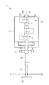
- the engine 1 is, for example, a marine diesel engine, and is disposed inside the hull of the ship, and includes a crankshaft 2 and an engine body 3 as shown in FIG.
- the crankshaft 2 includes a pin portion connected to one end of the connecting rod, a journal portion supported by the pin portion and disposed on the axis 10, and an arm portion connecting the pin portion and the journal portion.
- the engine body 3 includes a base plate 6 and a main bearing 7.
- the base plate 6 is fixed to the hull and forms a storage space 8 therein.
- the crankshaft 2 has a pin portion and an arm portion stored in a storage space 8 inside the engine body 3, and both ends are disposed outside the storage space 8.
- the main bearings 7 are each disposed in the storage space 8, and the crankshaft 2 can rotate about the axis 10.
- the engine body 3 further includes a connecting rod (not shown) corresponding to the pin portion and a piston (not shown). Each piston is supported so as to be linearly movable.
- the connecting rod has a small end coupled to the cross head pin and a large end coupled to the pin portion of the crankshaft 2.
- the engine body 3 reciprocates the pistons by burning fuel inside a cylinder (not shown).
- the connecting rod rotates the crankshaft 2 by transmitting the reciprocating motion of the piston to the pin portion of the crankshaft 2.
- the engine body 3 further includes a thrust bearing 11, a longitudinal vibration damper 12, and a rear end side oil seal 15.
- the thrust bearing 11 is disposed on the rear end side of the crankshaft 2 and receives a thrust force so that the crankshaft 2 does not move in the axial direction.
- the longitudinal vibration damper 12 is disposed on the front end side of the crankshaft 2 and forms oil chambers 12a and 12b filled with a lubricant between the crankshaft 2 and the axis of the crankshaft 2 as shown in FIG. Damping direction vibration.
- the rear end side oil seal 15 is disposed in a portion where the rear end side of the crankshaft 2 penetrates the casing of the engine body 3, and the lubricant in the storage space 8 leaks to the outside through a gap connecting to the storage space 8. prevent.
- the engine 1 includes a flywheel 16 on the front end side of the engine 1.
- the flywheel 16 is formed in a disk shape.
- the flywheel 16 has a circular bottom surface disposed perpendicular to the axis, and a center of gravity disposed on the axis.
- the flywheel 16 is fixed to the front end of the crankshaft 2. Note that the flywheel 16 may be disk-shaped and does not necessarily have to be a perfect circle.
- the casing 18 is disposed on the front end side of the engine body 3 and forms a space in which the flywheel 16 is stored.
- the ship equipped with the engine 1 includes a propeller shaft 21, a propeller 22, and an intermediate shaft 23.
- the propeller shaft 21 is formed in a rod shape, one end is disposed outside the hull, the other end is disposed inside the hull, and is rotatably supported by the hull.
- the propeller 22 is formed in an airfoil shape and is fixed to an end portion of the propeller shaft 21 disposed outside the hull.
- the propeller 22 propels the hull by being rotated together with the propeller shaft 21.
- the intermediate shaft 23 is formed in a rod shape. One end of the intermediate shaft 23 is joined to the rear end portion of the crankshaft 2, and the other end is joined to an end portion disposed inside the hull of the propeller shaft 21.
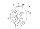
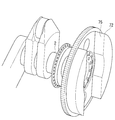
- FIG. 2 shows the flywheel 16.
- the flywheel 16 has an engine body side surface 24 and a side surface 25.
- the engine body side surface 24 is one of the two bottom surfaces of the flywheel 16.
- the side surface 25 is a side surface of the flywheel 16 having a disk shape.
- the flywheel 16 is arranged so that the axis 26 of the disc overlaps the axis 10, and the engine body side surface 24 is arranged to face the engine body 3.
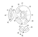
- the flywheel 16 includes a main body 27, a first divided member 28, and a second divided member 29. Moreover, as shown in FIG. 3, the fastening part 31 is formed in the main-body part 27. As shown in FIG. The main body 27 is fixed to the crankshaft 2 by fixing the fastening portion 31 to the front end of the crankshaft 2 using bolts.
- the main body 27 has an engine main body side surface 32, a side surface 33, a first split member mounting surface 34, and a second split member mounting surface 35.
- the first divided member mounting surface 34 and the second divided member mounting surface 35 are adjacent to each other.
- the main body 27 is further formed with a convex portion 30 that protrudes toward the engine main body 3 from the first split member mounting surface 34 and the second split member mounting surface 35.
- the engine main body side surface 32 is formed on the convex portion 30 so as to be parallel to the first divided member attaching surface 34 and the second divided member attaching surface 35. That is, the engine main body side surface 32 is disposed closer to the engine main body 3 than the first split member mounting surface 34 and the second split member mounting surface 35.
- a plurality of first screw holes 36 are formed in the first divided member mounting surface 34.
- a plurality of second screw holes 37 are formed in the second split member mounting surface 35.
- the first divided member attachment surface 34 and the second divided member attachment surface 35 do not necessarily have to be parallel to the engine body side surface 32, and the first divided member 28 and the second divided member 29 are the main body portion 27. Any surface that can be attached to the surface may be used.
- the first divided member 28 is formed in a fan-like plate shape, and has an engine main body side surface 41 and side surfaces 42.
- the first divided member 28 has a plurality of first through holes 43 corresponding to the plurality of first screw holes 36.
- the first through hole 43 coincides with the position of the first screw hole 36 when the first divided member 28 is attached to the first divided member attachment surface 34, and the first through hole 43 and the axis of the first screw hole 36.
- the direction is parallel to the axis 26.
- the second divided member 29 is formed in a fan-like plate shape, and has an engine main body side surface 44 and a side surface 45.
- the second divided member 29 has a plurality of second through holes 46 corresponding to the plurality of second screw holes 37.
- the second through hole 46 coincides with the position of the second screw hole 37 when the second divided member 29 is attached to the second divided member attachment surface 35, and the axis of the second through hole 46 and the second screw hole 37.
- the direction is parallel to the axis 26.
- the shapes of the first divided member 28 and the second divided member 29 are fan-shaped, but the shapes are matched to the shapes of the main body 27, the first divided member 28, and the second divided member 29, respectively. It can be deformed.
- a plurality of first bolts are inserted into the plurality of first screw holes 36, and a plurality of second bolts are inserted into the plurality of second screw holes 37, respectively.
- first divided member 28 is attached to the first divided member attachment surface 34 of the main body 27, the plurality of first bolts are arranged in parallel to the axis 26.
- the first divided member 28 is fixed to the main body portion 27 by the first bolt passing through the first through hole 43 and being fastened to the plurality of first screw holes 36.
- the second divided member 29 is attached to the second divided member attachment surface 35 of the main body 27, the plurality of second bolts are arranged in parallel to the axis 26.
- the second divided member 29 is fixed to the main body portion 27 by the second bolt passing through the second through hole 46 and being fastened to the second screw hole 37.
- the engine main body side surface 32 of the main body portion 27 When the first split member 28 and the second split member 29 are attached to the main body portion 27, the engine main body side surface 32 of the main body portion 27, the engine main body side surface 41 of the first split member 28, and the second split member 29.
- the engine main body side surface 44 of the flywheel constitutes the engine main body side surface 24 of the flywheel 16.
- the side surface 33 of the main body 27, the side surface 42 of the first divided member 28, and the side surface 45 of the second divided member 29 are 16 side surfaces 25 are formed.
- the flywheel 16 is provided on the front end side of the engine 1
- the present invention is not limited to this example. That is, a rear end side flywheel similar to the flywheel 16 may be provided on the rear end side of the engine 1.
- the rear end side flywheel may have a disk shape and does not necessarily have to be a perfect circle.
- the circular bottom surface is arranged perpendicular to the axis, and the center of gravity is arranged on the axis.
- the rear end side flywheel is fixed to the end on the rear end side of the crankshaft 2.
- the dividing member is detachably provided on the engine body side.
- the engine 1 generates rotational power by burning fuel, and rotates the crankshaft 2 around the axis.
- the propeller shaft 21 propels the hull by rotating the propeller 22 using the rotational power transmitted from the crankshaft 2 via the intermediate shaft 23.
- the rotational speed of the crankshaft 2 fluctuates due to the reciprocating timing of the plurality of pistons of the engine body 3 or the resistance applied to the propeller 22 fluctuates, and torsional vibration occurs.
- the flywheel 16 rotates around the axis 10 together with the crankshaft 2 when the crankshaft 2 rotates.
- the flywheel 16 applies torque to the crankshaft 2 so that fluctuations in the rotational speed of the crankshaft 2 become small when the rotational speed of the crankshaft 2 changes due to the moment of inertia of the flywheel 16. 2 torsional vibration generated.
- the rear end side flywheel also reduces the rotational fluctuation of the crankshaft 2 and the torsional vibration generated in the crankshaft 2 in the same manner as the flywheel 16.
- the crankshaft 2 is fixed at a predetermined angle, and the first divided member 28 and the second divided member 29 of the flywheel 16 are arranged at predetermined positions.
- the crankshaft 2 is fixed at a predetermined angle, the first split member 28 and the second split member 29 are removed from the main body 27.
- the predetermined angle refers to an angle at which the space formed when the first divided member 28 and the second divided member 29 are removed becomes a space where workers can easily work, or the first divided member 28. And the angle at which the second split member 29 can be easily removed.
- the flywheel 16 can be brought closer to the engine body 3, and the distance between the center of gravity of the flywheel 16 and the main bearing of the engine body 3 can be shortened. As a result, bending that occurs in the crankshaft 2 can be reduced, the crankshaft 2 can be prevented from hitting the main bearing 7, and damage to the main bearing 7 can be prevented.
- the rear end side flywheel also has the same effect as the flywheel 16.
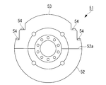
- the flywheel 51 according to the present embodiment is applied to, for example, a flywheel provided on the front end side.
- the flywheel 51 is formed in a disk shape, and includes a main body portion 52, a dividing member 53, and a plurality of bolts 54.
- the main body 52 is fixed to the crankshaft 2 and has a mounting surface 52a including a diameter direction of a disk formed by the flywheel 51.
- the dividing member 53 is formed in a semicircular plate shape.
- the split wheel 53 is attached to the attachment surface 52a of the main body 52, whereby the flywheel 51 is formed.
- the dividing member 53 forms a part of the side surface (side surface of the disk) of the flywheel 51 and faces the engine body 3 of the flywheel 51 (on the disk side). Part of the bottom surface).
- Each of the plurality of bolts 54 is arranged in a direction perpendicular to the mounting surface 52a of the main body 52.
- the bolt 54 penetrates the split member 53 and is fastened to the main body portion 52, whereby the split member 53 is fixed to the main body portion 52 and both are integrated.
- the engine including the flywheel 51 according to the present embodiment can easily maintain the longitudinal vibration damper 12 by removing the dividing member 53.
- the flywheel 51 is not limited to the front end side, and can be applied to a flywheel provided on the rear end side.
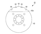
- the flywheel 61 according to the present embodiment is applied to, for example, a flywheel provided on the front end side.
- the flywheel 61 is formed in a disc shape and includes a main body 62, a dividing member 63, and a plurality of bolts 64.
- the flywheel 61 may be disc-shaped and does not necessarily have to be a perfect circle.
- the main body 62 is fixed to the crankshaft 2, and a mounting surface 62 a is formed on a string corresponding to a center angle smaller than 180 degrees of the flywheel 61.
- the split member 63 When the split member 63 is viewed from the front, it has a shape surrounded by an arc corresponding to a central angle smaller than 180 degrees and a chord corresponding to the central angle.
- the flywheel 61 By attaching the dividing member 63 to the attachment surface 62 a of the main body 62, the flywheel 61 is formed.
- the split member 63 When attached to the main body 62, the split member 63 forms a part of the side surface (side surface of the disk) of the flywheel 61 and faces the engine body 3 of the flywheel 61 (on the disk side). Part of the bottom surface).
- the plurality of bolts 64 are respectively arranged in a direction perpendicular to the mounting surface 62a of the main body 62.
- the bolt 64 penetrates the split member 63 and is fastened to the main body portion 62, whereby the split member 63 is fixed to the main body portion 62 and both are integrated.
- the engine including the flywheel 61 can easily maintain the longitudinal vibration damper 12 by removing the dividing member 63.
- the flywheel 61 is not limited to the front end side, and can be applied to a flywheel provided on the rear end side.
- FIG. 6 is a schematic view showing an engine and a propeller according to a fourth embodiment of the present invention.
- a rear end flywheel 71 is installed between the intermediate shaft 23 and the engine body 3.
- the rear end side flywheel 71 is formed in a disk shape and includes a main body 72, a first divided member 73, a second divided member 74, and the like. It should be noted that the rear end side flywheel 71 may be disc-shaped and does not necessarily have to be a perfect circle.
- the main body 72 is fixed to the crankshaft 2 and has a notch 75.
- the notch 75 is formed on the intermediate shaft side surface facing the intermediate shaft 23 (see FIG. 6) of the two bottom surfaces of the disk formed by the rear end side flywheel 71.
- the notch 75 is formed in a string corresponding to a center angle smaller than 180 degrees of the rear end side flywheel 71.
- the first divided member 73 is attached to one side of the notch 75 with respect to the shaft of the rear end side flywheel 71, and the second divided member 74 is included in the notch 75.
- the rear end side flywheel 71 is attached to the other shaft.
- the intermediate shaft 23 is moved toward the center of the main body 72 so that the end of the intermediate shaft 23 passes through the notch 75 of the main body 72. Thereby, the intermediate shaft 23 can be attached and fixed to the crankshaft 2. Thereafter, the first divided member 73 and the second divided member 74 are attached to the main body 72.
- the intermediate shaft 23 can be taken out from the main body 72 by rotating the flywheel 71 on the rear end side and positioning one of the first divided member 73 and the second divided member 74 above the shaft. That is, the intermediate shaft 23 can be set to a removable position by rotating the rear end side flywheel 71 by 90 ° at the maximum.
- the cutout 75 may be formed in the main body portion only in one of the radial directions with respect to the axis of the rear end side flywheel 71 and only the first divided member 73 may be attached to and detached from the main body portion. That is, the main body portion of this modification has a shape in which the main body portion 72 and the second divided member 74 of the above embodiment are integrated.
- the intermediate shaft 23 can be removed upward from the main body only when the rear end side flywheel 71 is rotated so that the first split member 73 is positioned above the shaft.
Landscapes
- Engineering & Computer Science (AREA)
- General Engineering & Computer Science (AREA)
- Mechanical Engineering (AREA)
- Physics & Mathematics (AREA)
- Acoustics & Sound (AREA)
- Aviation & Aerospace Engineering (AREA)
- Ocean & Marine Engineering (AREA)
- Chemical & Material Sciences (AREA)
- Combustion & Propulsion (AREA)
- Shafts, Cranks, Connecting Bars, And Related Bearings (AREA)
- Connection Of Motors, Electrical Generators, Mechanical Devices, And The Like (AREA)
Abstract
本発明によるエンジンは、軸線を中心に回転するクランク軸と、円板形状を有し、中心にてクランク軸の軸線に接続されたはずみ車(16)とを備え、はずみ車(16)は、クランク軸に固定される本体部(27)と、本体部(27)に着脱可能に固定される第1分割部材(28)及び第2分割部材(29)とを有し、第1分割部材(28)及び第2分割部材(29)は、本体部(27)に固定されたときに、はずみ車(16)の側面の一部と、はずみ車(16)の二つの円形状底面のうちエンジン本体に対向する底面の一部を形成する。
Description
本発明は、はずみ車及びエンジンに関する。
エンジン(機関)のクランク軸は、主軸受を介してエンジン本体の台板によって支えられ、はずみ車(フライホイール)は、クランク軸の前端側又は後端側に取り付けられる。はずみ車は、燃焼行程における余分なエネルギーを吸収しつつ、他の行程で、はずみ車の回転慣性力のエネルギーを用いることで、クランク軸の回転を円滑にさせる。下記の特許文献1には、フライホイールに関する発明であって、フライホイールボディに脱着自在に取り付けられたウェイトセグメントを備え、慣性モーメントを自由に調整することが開示されている。
特許文献1のフライホイールボディは、フライホイールボディの外殻部の中にウェイトセグメントを積み重ねて設置することで、慣性力を変化させることができるように設計されている。このようなフライホイールボディを船舶に採用した場合、外殻部の中にウェイトセグメントを設置することとなるため、外殻部を大きくしなければならない。このため、フライホイールボディの全長が大きくなり、結果としてエンジンが設置される機関室を大きくする必要が生じていた。
また、特許文献1は、フライホイールボディと機関本体との位置関係やウェイトセグメントを積み重ねる方向について一切考慮されていない。フライホイールボディと機関本体との間隔が大きい場合、又は機関本体側とは反対方向にウェイトセグメントを積み重ねる場合は、機関本体に設けられるクランク軸のたわみ量が大きくなるため、クランク軸を支える主軸受に方当たりして損傷の原因となっていた。一方、フライホイールボディと機関本体との間隔が近い場合、又は機関本体側にウェイトセグメントを積み重ねる場合は、機関本体とフライホイールボディとの間のメンテナンススペースが確保できなくなるため、メンテナンスのたびにフライホイール自体を外す等の作業が必要になっていた。さらに船舶等の大型機関用のフライホイールは重量も大きいため、フライホイールを外すための工事が必要となっていた。
本発明は、慣性モーメントを適切に変化できる一方、エンジンメンテナンスの簡易化が可能なはずみ車を提供することを目的とする。
本発明の第1の態様に係るはずみ車は、本体部と、前記本体部に着脱可能に固定される分割部材と、を備えるはずみ車であって、前記分割部材が前記本体部に固定されたときに、前記分割部材が外周面の一部を形成する。
この構成によれば、本体部から分割部材を取り外すことにより、分割部材が固定されていた部分に空間を形成することができ、その空間を作業スペースとして、はずみ車の周辺に配置された部品を容易に取り扱うことができる。
この構成によれば、本体部から分割部材を取り外すことにより、分割部材が固定されていた部分に空間を形成することができ、その空間を作業スペースとして、はずみ車の周辺に配置された部品を容易に取り扱うことができる。
本発明の第2の態様に係るエンジンは、前記第1の態様に係るはずみ車と、前記本体部が設置されるクランク軸と、を備える。
この構成によれば、本体部から分割部材を取り外すことにより、分割部材が固定されていた部分に空間を形成することができ、その空間を作業スペースとして、クランク軸の周辺に配置された部品を容易に取り扱うことができる。
この構成によれば、本体部から分割部材を取り外すことにより、分割部材が固定されていた部分に空間を形成することができ、その空間を作業スペースとして、クランク軸の周辺に配置された部品を容易に取り扱うことができる。
前記第2の態様に係るエンジンの前記はずみ車は、前記本体部が前記クランク軸の前端部に設置されるとともに、前記分割部材が前記本体部に固定されたときに、前記エンジンに対向するエンジン側表面の一部を形成してもよい。
この構成によれば、本体部から分割部材を取り外すことにより、エンジン本体と本体部と間に空間を形成することができ、その空間を作業スペースとして、はずみ車とエンジン本体の間に配置された部品を容易に取り扱うことができる。
この構成によれば、本体部から分割部材を取り外すことにより、エンジン本体と本体部と間に空間を形成することができ、その空間を作業スペースとして、はずみ車とエンジン本体の間に配置された部品を容易に取り扱うことができる。
前記第2の態様に係るエンジンは、前記クランク軸に接続される後端部に接続される中間軸をさらに備え、前記はずみ車は、前記本体部が前記クランク軸の後端部に設置されるとともに、前記分割部材が前記本体部に固定されたときに、前記中間軸に対向する中間軸側表面の一部を形成する。
この構成によれば、本体部から分割部材を取り外すことにより、クランク軸から中間軸を脱着することができる。中間軸がクランク軸に着脱されるときに中間軸が通過する領域に分割部材を固定することで、分割部材分の重量をはずみ車に追加することができ、はずみ車の厚さや直径を増加させることなく、はずみ車の慣性モーメントを増加させることができる。
この構成によれば、本体部から分割部材を取り外すことにより、クランク軸から中間軸を脱着することができる。中間軸がクランク軸に着脱されるときに中間軸が通過する領域に分割部材を固定することで、分割部材分の重量をはずみ車に追加することができ、はずみ車の厚さや直径を増加させることなく、はずみ車の慣性モーメントを増加させることができる。
前記第2の態様に係るエンジンにおいて、前記分割部材は、前記回転軸に対して垂直方向に、前記本体部に着脱されてもよい。
この構成によれば、分割部材の着脱の際、回転軸方向に分割部材を移動させなくてもよいため、分割部材の着脱のためにエンジンの軸方向の長さを増加させる必要がない。
前記第2の態様に係るエンジンにおいて、前記分割部材は、軸線方向に対して垂直方向に、前記本体部に着脱されてもよい。
この構成によれば、分割部材の着脱の際、軸線方向に分割部材を移動させなくてもよいため、分割部材の着脱のためにエンジンの軸方向の長さを増加させる必要がない。
この構成によれば、分割部材の着脱の際、回転軸方向に分割部材を移動させなくてもよいため、分割部材の着脱のためにエンジンの軸方向の長さを増加させる必要がない。
前記第2の態様に係るエンジンにおいて、前記分割部材は、軸線方向に対して垂直方向に、前記本体部に着脱されてもよい。
この構成によれば、分割部材の着脱の際、軸線方向に分割部材を移動させなくてもよいため、分割部材の着脱のためにエンジンの軸方向の長さを増加させる必要がない。
本発明によれば、クランク軸のねじり振動を低減するために、大きな慣性力が必要な場合があり、慣性力を増加させる場合において、分割できない従来のはずみ車と異なり、はずみ車とエンジン本体間の部品の組立やメンテナンスのための作業スペースを確保することができ、かつ、はずみ車の重心位置と主軸受の距離を離す必要がないため、クランク軸のたわみ量を増加させない。
<第1実施形態>
以下、図面を参照して、本発明の第1実施形態に係るエンジンを説明する。エンジン1は、例えば舶用ディーゼル機関であり、船舶の船体内部に配置され、図1に示されているように、クランク軸2とエンジン本体3とを備えている。クランク軸2は、連接棒の一端と接続されるピン部と、ピン部に支持され軸線10上に配置されるジャーナル部、及び、ピン部及びジャーナル部を結ぶアーム部を備えている。
以下、図面を参照して、本発明の第1実施形態に係るエンジンを説明する。エンジン1は、例えば舶用ディーゼル機関であり、船舶の船体内部に配置され、図1に示されているように、クランク軸2とエンジン本体3とを備えている。クランク軸2は、連接棒の一端と接続されるピン部と、ピン部に支持され軸線10上に配置されるジャーナル部、及び、ピン部及びジャーナル部を結ぶアーム部を備えている。
エンジン本体3は、台板6と主軸受7とを備えている。台板6は、船体に固定されており、内部に収納空間8を形成している。クランク軸2は、ピン部及びアーム部がエンジン本体3内部の収納空間8に収納され、かつ、両端が収納空間8の外部に配置されている。主軸受7は、それぞれ、収納空間8に配置され、軸線10を中心にクランク軸2が回転することができる。
エンジン本体3は、さらに、ピン部に対応する連接棒(図示せず)とピストン(図示せず)とを備えている。ピストンは、それぞれ、直線運動可能に支持されている。連接棒は、小端部がクロスヘッドピンに結合され、大端部がクランク軸2のピン部に結合されている。エンジン本体3は、シリンダ(図示せず)内部で燃料を燃焼させることにより、ピストンをそれぞれ往復運動させる。連接棒は、ピストンの往復運動をクランク軸2のピン部に伝達することにより、クランク軸2を回転させる。
エンジン本体3は、さらに、スラスト軸受11と、縦振動ダンパー12と、後端側オイルシール15とを備えている。スラスト軸受11は、クランク軸2の後端側に配置され、クランク軸2が軸線方向に移動しないようにスラスト力を受けている。縦振動ダンパー12は、クランク軸2の前端側に配置され、図1に示すように、クランク軸2との間に潤滑剤で満たされた油室12a、12bを形成し、クランク軸2における軸線方向の振動を減衰させる。
後端側オイルシール15は、クランク軸2の後端側がエンジン本体3のケーシングを貫通する部分に配置され、収納空間8と接続する隙間を、収納空間8内の潤滑剤が外部に漏洩することを防ぐ。
エンジン1は、エンジン1の前端側に、はずみ車16を備えている。はずみ車16は、円板状に形成されている。はずみ車16は、円形状の底面が軸線に対して垂直に配置され、かつ、重心が軸線上に配置される。はずみ車16は、クランク軸2の前端側の端に固定されている。なお、はずみ車16は円板状であればよく、必ずしも真円である必要はない。
ケーシング18は、エンジン本体3の前端側に配置され、はずみ車16が収納される空間を形成している。
エンジン1を備える船舶は、プロペラ軸21とプロペラ22と中間軸23とを備えている。プロペラ軸21は、棒状に形成され、一端が船体の外部に配置され、他端が船体の内部に配置され、回転可能に船体に支持されている。プロペラ22は、翼形に形成され、プロペラ軸21の船体の外部に配置されている端部に固定されている。プロペラ22は、プロペラ軸21とともに回転されることにより、船体を推進させる。中間軸23は、棒状に形成されている。中間軸23は、一端がクランク軸2の後端部に接合され、他端がプロペラ軸21の船体の内部に配置されている端部に接合されている。
図2は、はずみ車16を示している。はずみ車16は、エンジン本体側表面24と側面25を有する。エンジン本体側表面24は、はずみ車16の2つの底面のうちの1つである。側面25は、円板状を有するはずみ車16の側面である。はずみ車16は、円板の軸線26が軸線10に重なるように配置され、かつ、エンジン本体側表面24がエンジン本体3に対向して配置されている。
はずみ車16は、本体部27と、第1分割部材28と、第2分割部材29とを備えている。また、本体部27は、図3に示すように、締結部分31が形成されている。本体部27は、ボルトを用いて締結部分31がクランク軸2の前端に固定されることにより、クランク軸2に固定される。
本体部27は、エンジン本体側表面32と、側面33と、第1分割部材取り付け面34と、第2分割部材取り付け面35とが形成されている。第1分割部材取り付け面34及び第2分割部材取り付け面35は、互いに隣接している。本体部27は、さらに、第1分割部材取り付け面34及び第2分割部材取り付け面35よりエンジン本体3の側に突出する凸部30が形成されている。エンジン本体側表面32は、第1分割部材取り付け面34及び第2分割部材取り付け面35に平行になるように凸部30に形成されている。すなわち、エンジン本体側表面32は、第1分割部材取り付け面34及び第2分割部材取り付け面35よりエンジン本体3の側に配置されている。第1分割部材取り付け面34には、複数の第1ねじ穴36が形成されている。第2分割部材取り付け面35には、複数の第2ねじ穴37が形成されている。なお、第1分割部材取り付け面34及び第2分割部材取り付け面35は、必ずしもエンジン本体側表面32に平行な面でなくてもよく、第1分割部材28及び第2分割部材29が本体部27に取り付け可能な面であればよい。
第1分割部材28は、図3に示すように、扇形の板状に形成され、エンジン本体側表面41と側面42とが形成されている。第1分割部材28は、複数の第1ねじ穴36に対応する複数の第1貫通孔43が形成されている。第1貫通孔43は、第1分割部材取り付け面34に第1分割部材28が取り付けられたとき、第1ねじ穴36の位置と一致し、第1貫通孔43と第1ねじ穴36の軸方向は、軸線26に対して平行である。
第2分割部材29は、図3に示すように、扇形の板状に形成され、エンジン本体側表面44と側面45とが形成されている。第2分割部材29は、複数の第2ねじ穴37に対応する複数の第2貫通孔46が形成されている。第2貫通孔46は、第2分割部材取り付け面35に第2分割部材29が取り付けられたとき、第2ねじ穴37の位置と一致し、第2貫通孔46と第2ねじ穴37の軸方向は、軸線26に対して平行である。
なお、本実施形態では、第1分割部材28及び第2分割部材29の形状を扇形としたが、本体部27、第1分割部材28及び第2分割部材29のそれぞれの形状に合わせて形状を変形することができる。
なお、本実施形態では、第1分割部材28及び第2分割部材29の形状を扇形としたが、本体部27、第1分割部材28及び第2分割部材29のそれぞれの形状に合わせて形状を変形することができる。
はずみ車16は、複数の第1ねじ穴36それぞれに複数の第1ボルトが挿入され、複数の第2ねじ穴37それぞれに複数の第2ボルトが挿入される。本体部27の第1分割部材取り付け面34に第1分割部材28が取り付けられたとき、複数の第1ボルトは、軸線26に対して平行に配置される。第1ボルトが第1貫通孔43を貫通して複数の第1ねじ穴36に締結されることにより、第1分割部材28が本体部27に固定される。本体部27の第2分割部材取り付け面35に第2分割部材29が取り付けられたとき、複数の第2ボルトは、軸線26に対して平行に配置される。第2ボルトが第2貫通孔46を貫通して第2ねじ穴37に締結されることにより、第2分割部材29が本体部27に固定される。
第1分割部材28と第2分割部材29が本体部27に取り付けられたとき、本体部27のエンジン本体側表面32と、第1分割部材28のエンジン本体側表面41と、第2分割部材29のエンジン本体側表面44は、はずみ車16のエンジン本体側表面24を構成する。第1分割部材28と第2分割部材29が本体部27に取り付けられたとき、本体部27の側面33と、第1分割部材28の側面42と、第2分割部材29の側面45は、はずみ車16の側面25を構成する。
なお、上述した説明では、エンジン1の前端側にはずみ車16を備える場合について説明したが、本発明はこの例に限定されない。すなわち、エンジン1の後端側にはずみ車16と同様の後端側はずみ車が設けられてもよい。なお、後端側はずみ車は円板状であればよく、必ずしも真円である必要はない。後端側はずみ車は、円形状の底面が軸線に対して垂直に配置され、かつ、重心が軸線上に配置される。後端側はずみ車は、クランク軸2の後端側の端に固定される。また、後端側はずみ車においても、はずみ車16と同様に、分割部材がエンジン本体側に着脱可能に設けられる。
エンジン1は、燃料を燃焼させることにより回転動力を生成し、軸線周りにクランク軸2を回転させる。プロペラ軸21は、中間軸23を介してクランク軸2から伝達される回転動力を用いて、プロペラ22を回転させることにより、船体を推進させる。このとき、クランク軸2は、エンジン本体3の複数のピストンが往復運動するタイミングがずれていたり、プロペラ22に印加される抵抗が変動することにより、回転速度が変動し、ねじり振動が発生する。
はずみ車16は、クランク軸2が回転することにより、クランク軸2とともに軸線10周りに回転する。これにより、はずみ車16は、はずみ車16の慣性モーメントにより、クランク軸2の回転速度が変化したときに、クランク軸2の回転速度の変動が小さくなるようにクランク軸2にトルクを印加し、クランク軸2に発生するねじり振動を低減する。
なお、後端側はずみ車が設けられる場合、後端側はずみ車も、はずみ車16と同様に、クランク軸2が回転する回転変動を低減し、クランク軸2に発生するねじり振動を低減する。
なお、後端側はずみ車が設けられる場合、後端側はずみ車も、はずみ車16と同様に、クランク軸2が回転する回転変動を低減し、クランク軸2に発生するねじり振動を低減する。
次に、本実施形態に係るエンジン1のエンジンメンテナンス方法について説明する。
エンジン1が停止して回転動力を生成していないとき、クランク軸2を所定の角度に固定し、はずみ車16の第1分割部材28と第2分割部材29を所定の位置に配置する。クランク軸2が所定の角度に固定されているとき、第1分割部材28と第2分割部材29が本体部27から取り外される。ここで、所定の角度とは、第1分割部材28と第2分割部材29を取り外したとき形成される空間が、作業員の作業しやすい空間となるような角度、又は、第1分割部材28と第2分割部材29を取り外しやすい角度である。
エンジン1が停止して回転動力を生成していないとき、クランク軸2を所定の角度に固定し、はずみ車16の第1分割部材28と第2分割部材29を所定の位置に配置する。クランク軸2が所定の角度に固定されているとき、第1分割部材28と第2分割部材29が本体部27から取り外される。ここで、所定の角度とは、第1分割部材28と第2分割部材29を取り外したとき形成される空間が、作業員の作業しやすい空間となるような角度、又は、第1分割部材28と第2分割部材29を取り外しやすい角度である。
第1分割部材28と第2分割部材29が本体部27から取り外されることにより、本体部27とエンジン1との間にスペースが形成される。これにより、分割できない従来のはずみ車が設置されている場合と異なり、作業者は形成されたスペースに体の一部を入れることができ、縦振動ダンパー12を取り扱ったり、メンテナンスしたりすることができる。
その結果、作業スペースを設けるため、はずみ車16の重心をエンジン本体3から離れるようにはずみ車16を設置する必要がなく、エンジン1のサイズを増加させずに、メンテナンス性を向上させることができる。また、作業スペースを設けずに、エンジン本体3側にはずみ車16の厚さを大きくすることができるため、エンジン1のサイズを増加させずに、クランク軸2のねじり振動を低減するための大きな慣性力を得ることができる。
また、従来のはずみ車と比較して、はずみ車16をエンジン本体3に近づけることができ、はずみ車16の重心とエンジン本体3の主軸受との距離を短くすることができる。その結果、クランク軸2に生じる撓みを低減することができ、クランク軸2が主軸受7に片当りすることを低減し、主軸受7の損傷を防止することができる。
なお、後端側はずみ車についても、はずみ車16と同様の作用効果を奏する。
<第2実施形態>
次に、本発明の第2実施形態に係るはずみ車について説明する。
本実施形態に係るはずみ車51は、例えば前端側に設けられるはずみ車に適用される。はずみ車51は、図4に示されているように、円板状に形成され、本体部52と、分割部材53と、複数のボルト54とを備えている。本体部52は、クランク軸2に固定され、はずみ車51が形成する円板の直径方向を含む取り付け面52aが形成されている。分割部材53は、半円の板状に形成されている。分割部材53が本体部52の取り付け面52aに取り付けられることにより、はずみ車51が形成される。本体部52に取り付けられたとき、分割部材53は、はずみ車51の側面(円板の側面)の一部を形成し、かつ、はずみ車51のエンジン本体3に対向するエンジン本体側表面(円板の底面)の一部を形成する。
複数のボルト54は、それぞれ、本体部52の取り付け面52aに対して垂直方向に配置される。ボルト54は、分割部材53を貫通し、本体部52に締結されることにより、分割部材53が本体部52に固定され、両者が一体化する。
本実施形態に係るはずみ車51を備えたエンジンも、第1実施形態におけるエンジン1と同様に、分割部材53を取り外すことにより、縦振動ダンパー12を容易にメンテナンスできる。はずみ車51をエンジン本体3に近づけることで、クランク軸2の撓みを低減することができ、主軸受7の損傷を防止することができる。
はずみ車51は、前端側に限られず、後端側に設けられるはずみ車にも適用できる。
はずみ車51は、前端側に限られず、後端側に設けられるはずみ車にも適用できる。
<第3実施形態>
次に、本発明の第3実施形態に係るはずみ車について説明する。
本実施形態に係るはずみ車61は、例えば前端側に設けられるはずみ車に適用される。はずみ車61は、図5に示されているように、円板状に形成され、本体部62と、分割部材63と、複数のボルト64とを備えている。なお、はずみ車61は円板状であればよく、必ずしも真円である必要はない。本体部62は、クランク軸2に固定され、はずみ車61の180度より小さい中心角に対応する弦に取り付け面62aが形成されている。分割部材63を正面視すると、180度より小さい中心角に対応する円弧とその中心角に対応する弦とに囲まれた形状を有する。分割部材63が本体部62の取り付け面62aに取り付けられることにより、はずみ車61が形成される。本体部62に取り付けられたとき、分割部材63は、はずみ車61の側面(円板の側面)の一部を形成し、かつ、はずみ車61のエンジン本体3に対向するエンジン本体側表面(円板の底面)の一部を形成する。
複数のボルト64は、それぞれ、本体部62の取り付け面62aに対して垂直方向に配置される。ボルト64は、分割部材63を貫通し、本体部62に締結されることにより、分割部材63が本体部62に固定され、両者が一体化する。
本実施形態に係るはずみ車61を備えたエンジンも、第1実施形態におけるエンジン1と同様に、分割部材63を取り外すことにより、縦振動ダンパー12を容易にメンテナンスできる。はずみ車61をエンジン本体3に近づけることで、クランク軸2の撓みを低減することができ、主軸受7の損傷を防止することができる。
はずみ車61は、前端側に限られず、後端側に設けられるはずみ車にも適用できる。
はずみ車61は、前端側に限られず、後端側に設けられるはずみ車にも適用できる。
<第4実施形態>
次に、本発明の第4実施形態に係るはずみ車について説明する。図6は、本発明の第4実施形態に係るエンジン及びプロペラを示す概略図である。
本実施形態では、中間軸23とエンジン本体3の間に後端側はずみ車71が設置される。後端側はずみ車71は、図7に示されているように、円板状に形成され、本体部72と、第1分割部材73と、第2分割部材74などを備えている。なお、後端側はずみ車71は円板状であればよく、必ずしも真円である必要はない。本体部72は、図8に示されているように、クランク軸2に固定され、切り欠き75が形成されている。切り欠き75は、後端側はずみ車71が形成する円板の二つの底面のうちの中間軸23(図6参照)に対向する中間軸側表面に形成される。切り欠き75は、後端側はずみ車71の180度より小さい中心角に対応する弦に形成されている。
第1分割部材73は、図7に示されているように、切り欠き75のうち、後端側はずみ車71の軸に対して一方に取り付けられ、第2分割部材74は、切り欠き75のうち、後端側はずみ車71の軸に対して他方に取り付けられる。第1分割部材73と第2分割部材74は、本体部72の切り欠き75に取り付けられたとき、後端側はずみ車71の側面を形成し、かつ、後端側はずみ車71の中間軸側表面を形成する。
次に、本実施形態に係るエンジンのエンジンメンテナンス方法について説明する。
クランク軸2から中間軸23を取り外すとき、まず、クランク軸2を所定の角度に固定し、後端側はずみ車71の第1分割部材73と第2分割部材74を所定の位置に配置する。クランク軸2が所定の角度に固定されているときに、第1分割部材73と第2分割部材74のいずれか一方が本体部72から上方へ取り外される。これにより、中間軸23の端部が、切り欠き75を通過することが可能となる。第1分割部材73又は第2分割部材74が本体部72から取り外されているとき、作業者は、中間軸23をクランク軸2から取り外し、中間軸23の端部が本体部72の切り欠き75を通過するように、中間軸23を本体部72の径方向外側へ移動させる。これにより、中間軸23をクランク軸2から取り出すことができる。
クランク軸2から中間軸23を取り外すとき、まず、クランク軸2を所定の角度に固定し、後端側はずみ車71の第1分割部材73と第2分割部材74を所定の位置に配置する。クランク軸2が所定の角度に固定されているときに、第1分割部材73と第2分割部材74のいずれか一方が本体部72から上方へ取り外される。これにより、中間軸23の端部が、切り欠き75を通過することが可能となる。第1分割部材73又は第2分割部材74が本体部72から取り外されているとき、作業者は、中間軸23をクランク軸2から取り外し、中間軸23の端部が本体部72の切り欠き75を通過するように、中間軸23を本体部72の径方向外側へ移動させる。これにより、中間軸23をクランク軸2から取り出すことができる。
反対に、中間軸23をクランク軸2に取り付ける場合、中間軸23の端部が本体部72の切り欠き75を通過するように、中間軸23を本体部72の中心側へ移動させる。これにより、中間軸23をクランク軸2に取り付け固定できる。その後、第1分割部材73と第2分割部材74が、本体部72に取り付けられる。
後端側はずみ車71を回転させ、第1分割部材73と第2分割部材74のいずれか一方を軸に対して上側に位置させることで、中間軸23を本体部72から取り出すことができる。すなわち、後端側はずみ車71を最大でも90°だけ回転することによって、中間軸23を取り外し可能な位置に設定できる。
後端側はずみ車71を回転させ、第1分割部材73と第2分割部材74のいずれか一方を軸に対して上側に位置させることで、中間軸23を本体部72から取り出すことができる。すなわち、後端側はずみ車71を最大でも90°だけ回転することによって、中間軸23を取り外し可能な位置に設定できる。
従来の後端側はずみ車では、中間軸を取り出すため、本体部に中間軸を通過させることが可能な切り欠きを設けているのみであった。そのため、慣性モーメントを増加させるためには、はずみ車の厚さを厚くするか直径を大きくする必要があった。一方、本実施形態によれば、切り欠き75に第1分割部材73と第2分割部材74が設置されることから、従来の後端側はずみ車に比較して、厚さや直径を増加させることなく、後端側はずみ車71の慣性モーメントを増加させることができる。そして、大きな慣性力を得ることで、クランク軸2のねじり振動を低減することができる。
なお、上記実施形態では、本体部72に対して二つの分割部材、すなわち、第1分割部材73及び第2分割部材74を着脱可能にした例について説明したが、本発明はこの例に限定されない。例えば、切り欠き75は、本体部において、後端側はずみ車71の軸に対して径方向の一方にのみ形成され、本体部に第1分割部材73のみが着脱されるようにしてもよい。すなわち、この変形例の本体部は、上記実施形態の本体部72と第2分割部材74が一体化した形状を有する。本変形例では、第1分割部材73が軸に対して上側に位置するように後端側はずみ車71を回転させたときだけ、中間軸23を本体部から上方へ取り出すことができる。
1 :エンジン
2 :クランク軸
3 :エンジン本体
6 :台板
7 :主軸受
8 :収納空間
10:軸線
11:スラスト軸受
12:縦振動ダンパー
15:後端側オイルシール
16:はずみ車
18:ケーシング
21:プロペラ軸
22:プロペラ
23:中間軸
24:エンジン本体側表面
25:側面
26:軸線
27:本体部
28:第1分割部材
29:第2分割部材
31:締結部分
32:エンジン本体側表面
33:側面
34:第1分割部材取り付け面
35:第2分割部材取り付け面
36:第1ねじ穴
37:第2ねじ穴
41:エンジン本体側表面
42:側面
43:第1貫通孔
44:エンジン本体側表面
45:側面
46:第2貫通孔
51:はずみ車
52:本体部
53:分割部材
54:ボルト
61:はずみ車
62:本体部
63:分割部材
64:ボルト
71:後端側はずみ車
72:本体部
73:第1分割部材
74:第2分割部材
75:切り欠き
Claims (5)
- 本体部と、
前記本体部に着脱可能に固定される分割部材と、を備えるはずみ車であって、
前記分割部材が前記本体部に固定されたときに、前記分割部材が外周面の一部を形成するはずみ車。 - 請求項1に記載のはずみ車と、
前記本体部が設置されるクランク軸と、
を備えるエンジン。 - 前記はずみ車は、前記本体部が前記クランク軸の前端部に設置されるとともに、前記分割部材が前記本体部に固定されたときに、前記エンジンに対向するエンジン側表面の一部を形成する請求項2に記載のエンジン。
- 前記クランク軸に接続される後端部に接続される中間軸をさらに備え、
前記はずみ車は、前記本体部が前記クランク軸の後端部に設置されるとともに、前記分割部材が前記本体部に固定されたときに、前記中間軸に対向する中間軸側表面の一部を形成する請求項2又は3のいずれかに記載のエンジン。 - 前記分割部材は、軸線方向にに対して垂直方向に、前記本体部に着脱される請求項2から請求項4のいずれか一項に記載のエンジン。
Priority Applications (2)
| Application Number | Priority Date | Filing Date | Title |
|---|---|---|---|
| CN201580003500.3A CN105899844B (zh) | 2014-03-18 | 2015-03-16 | 飞轮以及船舶用柴油机 |
| KR1020167017288A KR101836022B1 (ko) | 2014-03-18 | 2015-03-16 | 관성 바퀴 및 선박용 디젤 기관 |
Applications Claiming Priority (2)
| Application Number | Priority Date | Filing Date | Title |
|---|---|---|---|
| JP2014-055062 | 2014-03-18 | ||
| JP2014055062A JP5931945B2 (ja) | 2014-03-18 | 2014-03-18 | はずみ車および舶用ディーゼル機関 |
Publications (1)
| Publication Number | Publication Date |
|---|---|
| WO2015141646A1 true WO2015141646A1 (ja) | 2015-09-24 |
Family
ID=54144613
Family Applications (1)
| Application Number | Title | Priority Date | Filing Date |
|---|---|---|---|
| PCT/JP2015/057773 WO2015141646A1 (ja) | 2014-03-18 | 2015-03-16 | はずみ車及びエンジン |
Country Status (4)
| Country | Link |
|---|---|
| JP (1) | JP5931945B2 (ja) |
| KR (1) | KR101836022B1 (ja) |
| CN (1) | CN105899844B (ja) |
| WO (1) | WO2015141646A1 (ja) |
Citations (5)
| Publication number | Priority date | Publication date | Assignee | Title |
|---|---|---|---|---|
| JPS51153901U (ja) * | 1975-06-03 | 1976-12-08 | ||
| JPS57102744U (ja) * | 1980-12-17 | 1982-06-24 | ||
| JPS61181142U (ja) * | 1985-05-02 | 1986-11-12 | ||
| JPH0234847U (ja) * | 1988-08-30 | 1990-03-06 | ||
| JP2012215146A (ja) * | 2011-04-01 | 2012-11-08 | Isuzu Motors Ltd | 動力装置とそれを搭載した車両、および共振音を低減する方法 |
Family Cites Families (9)
| Publication number | Priority date | Publication date | Assignee | Title |
|---|---|---|---|---|
| JPS63118442A (ja) | 1986-11-06 | 1988-05-23 | 三井建設株式会社 | 間仕切壁の組付け構造 |
| JPH0191045U (ja) * | 1987-12-07 | 1989-06-15 | ||
| JPH02154832A (ja) * | 1988-12-02 | 1990-06-14 | Honda Motor Co Ltd | エンジン用フライホイール |
| JP2545504Y2 (ja) * | 1991-12-11 | 1997-08-25 | 日野自動車工業株式会社 | トーショナルダンパ付き燃料噴射ポンプ |
| GB2290122B (en) * | 1994-06-10 | 1998-02-18 | Nigel Hurrion | Engine |
| JPH0893853A (ja) * | 1994-09-29 | 1996-04-12 | Mitsubishi Heavy Ind Ltd | 回転軸系捩り振動用動吸振器 |
| KR200184252Y1 (ko) | 1999-12-29 | 2000-06-01 | 대우중공업주식회사 | 가변 발란스 웨이트를 갖는 크랭크축 |
| JP2004053008A (ja) * | 2002-05-31 | 2004-02-19 | Fukoku Co Ltd | ビスカスダンパ |
| CN202182146U (zh) * | 2011-08-03 | 2012-04-04 | 吴能建 | 一种风冷柴油机飞轮组件 |
-
2014
- 2014-03-18 JP JP2014055062A patent/JP5931945B2/ja active Active
-
2015
- 2015-03-16 CN CN201580003500.3A patent/CN105899844B/zh active Active
- 2015-03-16 WO PCT/JP2015/057773 patent/WO2015141646A1/ja active Application Filing
- 2015-03-16 KR KR1020167017288A patent/KR101836022B1/ko active IP Right Grant
Patent Citations (5)
| Publication number | Priority date | Publication date | Assignee | Title |
|---|---|---|---|---|
| JPS51153901U (ja) * | 1975-06-03 | 1976-12-08 | ||
| JPS57102744U (ja) * | 1980-12-17 | 1982-06-24 | ||
| JPS61181142U (ja) * | 1985-05-02 | 1986-11-12 | ||
| JPH0234847U (ja) * | 1988-08-30 | 1990-03-06 | ||
| JP2012215146A (ja) * | 2011-04-01 | 2012-11-08 | Isuzu Motors Ltd | 動力装置とそれを搭載した車両、および共振音を低減する方法 |
Also Published As
| Publication number | Publication date |
|---|---|
| KR101836022B1 (ko) | 2018-03-07 |
| JP2015175516A (ja) | 2015-10-05 |
| KR20160084473A (ko) | 2016-07-13 |
| CN105899844B (zh) | 2017-10-24 |
| JP5931945B2 (ja) | 2016-06-08 |
| CN105899844A (zh) | 2016-08-24 |
Similar Documents
| Publication | Publication Date | Title |
|---|---|---|
| US9915317B2 (en) | Centrifugal pendulum | |
| CN106068400A (zh) | 扭转振动阻尼器 | |
| US20110017168A1 (en) | Weighted centrifugal clutch | |
| US7004294B2 (en) | Vibration absorber assembly | |
| JP6597652B2 (ja) | 内燃機関のバランス装置 | |
| JP4933761B2 (ja) | ピストンエンジンおよびピストンエンジンを駆動的に連結する方法 | |
| EP3284969A1 (en) | Vibration-damping device | |
| JPH0861431A (ja) | ダンパー組立体 | |
| JP4947793B2 (ja) | クランク装置 | |
| KR101714208B1 (ko) | 개별 회전 관성질량을 갖춘 토셔널 댐퍼와 이를 적용한 크랭크샤프트 | |
| RU2012158019A (ru) | Способ компенсации моментов масс узла привода и узел привода для осуществления способа | |
| JP5931945B2 (ja) | はずみ車および舶用ディーゼル機関 | |
| KR101490948B1 (ko) | 차량용 댐퍼 풀리 조립체 | |
| US20080016930A1 (en) | Coupling plate for engine-driven generator | |
| JP5180806B2 (ja) | 携帯型作業機の振動吸収継手 | |
| KR102515669B1 (ko) | 현가 시스템 | |
| JP2017129189A (ja) | エンジン | |
| KR101421018B1 (ko) | 다기통 엔진의 크랭크 축 | |
| CN202158136U (zh) | 一种新型二级平衡机构 | |
| JP6969711B1 (ja) | 推力発生装置 | |
| WO2023119354A1 (ja) | 発電専用のエンジン発電機ユニット | |
| JP7075316B2 (ja) | トーショナルダンパ | |
| JP7231381B2 (ja) | トルクコンバータ | |
| KR20090063484A (ko) | 엔진의 플라이휠 | |
| JP6613201B2 (ja) | 車両用駆動装置 |
Legal Events
| Date | Code | Title | Description |
|---|---|---|---|
| 121 | Ep: the epo has been informed by wipo that ep was designated in this application |
Ref document number: 15765932 Country of ref document: EP Kind code of ref document: A1 |
|
| ENP | Entry into the national phase |
Ref document number: 20167017288 Country of ref document: KR Kind code of ref document: A |
|
| NENP | Non-entry into the national phase |
Ref country code: DE |
|
| 122 | Ep: pct application non-entry in european phase |
Ref document number: 15765932 Country of ref document: EP Kind code of ref document: A1 |