WO2015141451A1 - コネクタ - Google Patents
コネクタ Download PDFInfo
- Publication number
- WO2015141451A1 WO2015141451A1 PCT/JP2015/056032 JP2015056032W WO2015141451A1 WO 2015141451 A1 WO2015141451 A1 WO 2015141451A1 JP 2015056032 W JP2015056032 W JP 2015056032W WO 2015141451 A1 WO2015141451 A1 WO 2015141451A1
- Authority
- WO
- WIPO (PCT)
- Prior art keywords
- connector
- shell
- contact
- folded
- rear direction
- Prior art date
Links
Images

Classifications
-
- H—ELECTRICITY
- H01—ELECTRIC ELEMENTS
- H01R—ELECTRICALLY-CONDUCTIVE CONNECTIONS; STRUCTURAL ASSOCIATIONS OF A PLURALITY OF MUTUALLY-INSULATED ELECTRICAL CONNECTING ELEMENTS; COUPLING DEVICES; CURRENT COLLECTORS
- H01R13/00—Details of coupling devices of the kinds covered by groups H01R12/70 or H01R24/00 - H01R33/00
- H01R13/648—Protective earth or shield arrangements on coupling devices, e.g. anti-static shielding
- H01R13/658—High frequency shielding arrangements, e.g. against EMI [Electro-Magnetic Interference] or EMP [Electro-Magnetic Pulse]
- H01R13/6581—Shield structure
- H01R13/6582—Shield structure with resilient means for engaging mating connector
-
- H—ELECTRICITY
- H01—ELECTRIC ELEMENTS
- H01R—ELECTRICALLY-CONDUCTIVE CONNECTIONS; STRUCTURAL ASSOCIATIONS OF A PLURALITY OF MUTUALLY-INSULATED ELECTRICAL CONNECTING ELEMENTS; COUPLING DEVICES; CURRENT COLLECTORS
- H01R12/00—Structural associations of a plurality of mutually-insulated electrical connecting elements, specially adapted for printed circuits, e.g. printed circuit boards [PCB], flat or ribbon cables, or like generally planar structures, e.g. terminal strips, terminal blocks; Coupling devices specially adapted for printed circuits, flat or ribbon cables, or like generally planar structures; Terminals specially adapted for contact with, or insertion into, printed circuits, flat or ribbon cables, or like generally planar structures
- H01R12/70—Coupling devices
- H01R12/71—Coupling devices for rigid printing circuits or like structures
- H01R12/72—Coupling devices for rigid printing circuits or like structures coupling with the edge of the rigid printed circuits or like structures
- H01R12/721—Coupling devices for rigid printing circuits or like structures coupling with the edge of the rigid printed circuits or like structures cooperating directly with the edge of the rigid printed circuits
-
- H—ELECTRICITY
- H01—ELECTRIC ELEMENTS
- H01R—ELECTRICALLY-CONDUCTIVE CONNECTIONS; STRUCTURAL ASSOCIATIONS OF A PLURALITY OF MUTUALLY-INSULATED ELECTRICAL CONNECTING ELEMENTS; COUPLING DEVICES; CURRENT COLLECTORS
- H01R24/00—Two-part coupling devices, or either of their cooperating parts, characterised by their overall structure
- H01R24/60—Contacts spaced along planar side wall transverse to longitudinal axis of engagement
Definitions
- the present invention relates to a connector provided with a shell having a shell contact portion that contacts a part of the mating connector.
- a connector (not shown) disclosed in Patent Document 1 includes this type of shell.
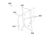
- the shell 900 of Patent Document 1 includes a main portion 910 having a front end 912, a folded portion 920 folded from the front end 912, and a spring portion 930 extending from the folded portion 920.
- the spring portion 930 is provided with a contact 932 that contacts a mating shell (not shown).
- the position of the contact 932 is too far from the front end 912 of the shell 900. For this reason, the contact (not shown) of the connector (not shown) and the contact (not shown) of the mating connector (not shown) before the contact 932 is connected to the mating shell (not shown). May connect to each other.
- an object of the present invention is to provide a connector having a structure in which the position of the contact is close to the front end of the shell.
- the connector includes a contact, a holding member that holds the contact, a shell, and a front protective member that is separate from the holding member.
- the shell has a shell main portion and a shell contact portion.
- the shell main portion at least partially covers the holding member.
- the shell contact portion is integrally formed with the shell main portion.
- the shell main part has a front end.
- the front end of the shell main portion includes a raised end portion.
- the shell contact portion has a folded portion and a spring portion.
- the folded portion protrudes forward in the front-rear direction from the starting end portion of the shell, and has a U-shaped cross section in a plane including the front-rear direction.
- the spring part includes a first part extending backward from the folded part, a second part extending forward, and a connecting part that connects the first part and the second part to each other. Yes.
- the second part is provided with a contact point that contacts a part of the mating connector.
- the front protection member is attached to the shell and has at least a protection part positioned in front of the folded part.
- the spring part according to the present invention has a first part extending backward from the folded part and a second part extending forward. Accordingly, the path length between the folded portion and the contact can be increased while bringing the contact close to the front end of the shell.
- the protection part according to the present invention is located in front of the folded part and protects the folded part. Thereby, it is possible to prevent the operator from hooking a finger or the like on the folded portion.
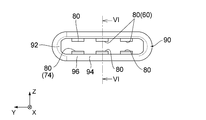
- FIG. 6 is a cross-sectional view showing the shell and the front protection member of FIG. 5 along the line VI--VI.
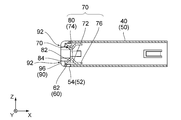
- FIG. 4 is an enlarged perspective view showing a front end of the connector shell of FIG. 3 and its vicinity.
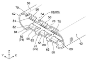
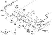
- FIG. 8 is an enlarged perspective view showing the shell of FIG. FIG. 8 is another enlarged perspective view showing the shell of FIG. 10 is a perspective view showing a part of a shell of Patent Document 1.
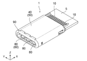
- the connector 1 according to the embodiment of the present invention is connected to a cable (not shown) through a paddle board 5. Further, the connector 1 is a mating connector (not shown) inserted at least partially from the ⁇ X side (front side) to the + X side (rear side) (backward) in the X direction (front-rear direction). And is to be fitted.
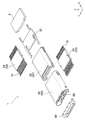
- the illustrated connector 1 includes a plurality of contacts 10 made of a conductor, a holding member 20 made of an insulator, a ground member 30 made of a conductor, a metal shell 40, and a front protective member 90 made of an insulator. And.
- the holding member 20 includes a main member 22 and two sub members 24. Each of the sub members 24 holds one row of contacts 10.
- the main member 22 accommodates the ground member 30 and the two sub members 24 together.
- the ground member 30 is sandwiched between two sub members 24 in the main member 22.
- the shell 40 is formed by pressing a single metal plate and then bending the pressed metal plate.
- the shell 40 has a shell main portion 50 and a shell contact portion 60.
- the shell main portion 50 covers the holding member 20.
- the shell contact portion 60 is formed integrally with the shell main portion 50.
- the shell main portion 50 has a substantially cylindrical shape extending in the X direction.
- the shell main portion 50 has a shape that is long in the Y direction (pitch direction), that is, a shape that is crushed in the Z direction (vertical direction).
- the front end 52 ( ⁇ X side end portion) of the shell main portion 50 includes a plurality of starting end portions 54 and a plurality of adjacent portions 56.
- the adjacent portion 56 is located adjacent to the starting end portion 54.
- the adjacent portion 56 has a size larger than that of the starting end portion 54 in the YZ plane orthogonal to the X direction.
- the starting end portion 54 and the adjacent portion 56 are divided into two sets.
- One set is located on the + Z side (upper side) of the shell main portion 50, and the other set is located on the ⁇ Z side (lower side) of the shell main portion 50.
- the group located on the + Z side has two starting end portions 54 and three adjacent portions 56.
- the group located on the ⁇ Z side has two starting end portions 54 and three adjacent portions 56.
- the shell contact portion 60 of the present embodiment is composed of two parts, a + Z side (upper side) part and a ⁇ Z side (lower side) part. Each of the two portions extends from the front end 52 of the shell main portion 50. Specifically, each of the two portions of the shell contact portion 60 includes two folded portions 62 and a spring portion 70.
- each of the folded-back portions 62 has a U-shaped cross section in the XZ plane. Each of the folded portions 62 protrudes in the ⁇ X direction (forward) from the starting end portion 54 of the shell main portion 50.
- Each of the spring parts 70 has two first parts 72, three second parts 74, and a connecting part 76 that connects the first part 72 and the second part 74 to each other in the Y direction.
- Each of the first portions 72 extends from the folded portion 62 in the + X direction (toward the rear).
- the illustrated first portion 72 has a relatively small and elongated plate shape.
- the connecting portion 76 extends from the + X side end (rear end) of the first portion 72 in the Y direction, and has a relatively large and slender plate shape.
- Each of the second portions 74 extends from the connecting portion 76 in the ⁇ X direction (toward the front).
- the plurality of second parts 74 included in the common spring part 70 are spaced apart from each other in the Y direction.
- the second portion 74 and the first portion 72 are located at different positions in the Y direction.
- Each of the second parts 74 is formed by bending a plate wider than the first part 72 so as to have a V-shape.
- the second part 74 is provided with a contact 80 and an invitation part 82.
- the contact 80 is the apex of the second part 74 on the inner side in the Z direction.
- the contact 80 is in contact with a part of a counterpart connector (not shown) (specifically, a counterpart ground portion, a counterpart shield portion, a counterpart shell, etc.).
- the invitation portion 82 is located on the ⁇ X side (front) of the contact 80.
- the invitation portion 82 has a surface that intersects the X direction.
- the second part 74 corresponds to the adjacent part 56.
- the second portion 74 can be made relatively long. If the adjacent part 56 is positioned behind the start part 54, the second part 74 can be made longer. However, in this case, a large opening may be formed at the front end of the shell 40. Therefore, as in the present embodiment, the position of the adjacent portion 56 in the X direction is preferably the same as the position of the starting end portion 54 in the X direction.
- the front end 84 of the second portion 74 (that is, the front end of the invitation portion 82) is located on the ⁇ X side (forward) of the start end portion 54.
- the contact 80 is located relatively forward.
- the entire spring portion 70 functions as a support spring that elastically supports the contact 80.
- the spring length of the support spring is determined by the path length from the folded portion 62 to the contact 80. Compared with a spring that simply extends toward the + X side of the shell 40, the spring portion 70 of the present embodiment can obtain a sufficient spring length while the contact point 80 is positioned relatively on the front side.
- a plurality of second parts 74 are spaced apart from each other in the Y direction.
- the plurality of contacts 80 are located at different positions in the Y direction. Therefore, the contact 80 can be reliably brought into contact with the mating connector (not shown) without being affected by variations in the shape of the mating connector (not shown). In other words, the contact 80 according to the present embodiment exhibits high contact reliability.
- each of the contacts 80 has a size larger than that of the folded portion 62 in the Y direction. Therefore, the shell 40 can contact a ground portion (not shown) of a mating connector (not shown) with a relatively large area.
- the front protective member 90 forms a closed circuit in the YZ plane orthogonal to the X direction.
- the front protection member 90 is closed in the YZ plane.
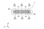
- the front protection member 90 has a flat annular shape when viewed from the ⁇ X side (front side).
- the front protection member 90 has a flat front end 92.
- the front end 92 of the front protective member 90 of the present embodiment forms a surface parallel to the YZ plane.
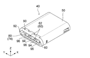
- the front protective member 90 includes a plurality of protection portions 94 and a plurality of buckling prevention portions 96.
- the protection part 94 is located on the ⁇ X side (front) of the folded part 62, respectively.
- the protective portion 94 of the present embodiment completely hides the folded portion 62 when the connector 1 is viewed from the ⁇ X side (front).
- the protection part 94 of the front protection member 90 protects the folded part 62 as described above. For this reason, it can prevent that the folding
- the buckling prevention portions 96 are provided corresponding to the second portions 74, respectively. More specifically, as shown in FIG. 6, the buckling prevention portion 96 is located on the ⁇ X side (front) of the front end 84 of the second portion 74 (that is, the front end of the invitation portion 82). As can be understood from FIGS. 2, 4, and 6, the buckling prevention portion 96 according to the present embodiment has the front end 84 of the second portion 74 when the connector 1 is viewed from the ⁇ X side (front). It is completely hidden. Therefore, when the connector 1 and the mating connector (not shown) are fitted, a part of the mating connector (not shown) hits the front end 84 of the second portion 74 and the second portion 74 buckles. Can be prevented.
- the holding member 20 of the above-described embodiment is divided into a total of three members including the main member 22 and the two sub members 24, the present invention is not limited to this.
- the holding member 20 may be composed of a single member.
- the connector 1 of the above-described embodiment includes the ground member 30, the present invention is not limited to this.
- the connector 1 may not include the ground member 30.
- the shell contact portion 60 of the above-described embodiment is divided into an upper part and a lower part, the present invention is not limited to this.
- the shell contact part 60 may have only the upper part.
- the upper portion may be pressed against the lower side of the shell main portion 50.
- the shell contact portion 60 includes the plurality of folded portions 62 and the plurality of contacts 80
- the present invention is not limited to this.
- the number of the folded portions 62 and the number of the contacts 80 may each be one.
- it is preferable that the number of the folded portions 62 and the number of the contacts 80 are each 2 or more.
- first part 72 and the second part 74 in the above-described embodiment are located at different positions in the Y direction, the present invention is not limited to this.
- the first part 72 and the second part 74 may be provided so as to overlap each other in the Z direction.
- the first portion 72 and the second portion 74 are positioned at different positions in the Y direction as in this embodiment, so that the relatively low profile is achieved. It is preferable to constitute a spring.
- the front protection member 90 of the above-described embodiment forms a closed circuit
- the present invention is not limited to this.
- the front protection member 90 may be divided into two members. These two members may protect the + Z side (upper side) portion of the shell contact portion 60 and the ⁇ Z side (lower side) portion of the shell contact portion 60, respectively.
- the front protection member 90 forms a closed circuit.
- the front protective member 90 of the above-described embodiment has the flat front end 92
- the present invention is not limited to this.
- the front protection member 90 may have some unevenness.
- the front end 92 is preferably flat.
- the protection part 94 of the above-described embodiment completely hides the folded part 62 when the connector 1 is viewed from the ⁇ X side (front)
- the present invention is not limited to this.
- the protective part 94 is positioned on the ⁇ X side (front) of the folded part 62 to prevent the folded part 62 from being caught, the folded part 62 is not seen when the connector 1 is viewed from the ⁇ X side (front). It may be partially visible.
- the present invention is based on Japanese Patent Application No. 2014-054780 filed with the Japan Patent Office on March 18, 2014, the contents of which are incorporated herein by reference.
Landscapes
- Details Of Connecting Devices For Male And Female Coupling (AREA)
Abstract
相手側コネクタと嵌合するコネクタは、シェル(40)とフロント保護部材(90)とを備える。シェル(40)は、シェル主部(50)とシェル接触部(60)とを有する。シェル主部(50)は、起端部(54)を含む前端(52)を有する。シェル接触部(60)は、折り返し部(62)とバネ部(70)とを有する。折り返し部(62)は、起端部(54)から前後方向において前方に突出すると共に、前後方向を含む面内においてU字状の断面を有する。バネ部(70)は、折り返し部(62)から後方に向かって延びる第1部(72)と、前方に向かって延びる第2部(74)と、第1部(72)及び第2部(74)を連結する連結部(76)とを有する。第2部(74)には接点(80)が設けられる。フロント保護部材(90)は、シェル(40)に取り付けられ、折り返し部(62)の前方に位置する保護部(94)を有する。
Description
本発明は、相手側コネクタの一部と接触するシェル接触部を有するシェルを備えたコネクタに関する。
例えば、特許文献1に開示されたコネクタ(図示せず)は、この種のシェルを備えている。図10に示されるように、特許文献1のシェル900は、前端912を有する主部910と、前端912から折り返された折り返し部920と、折り返し部920から延びるバネ部930とを有している。バネ部930には、相手側シェル(図示せず)に接触する接点932が設けられている。このように折り返し部920を設ける場合、主部910にバネ部930を形成する際に切り込み(開口)を形成する必要がない。このため、シェルのシールド特性が損なわれない。
特許文献1のシェル900においては、接点932の位置がシェル900の前端912から離れ過ぎている。このため、コネクタ(図示せず)のコンタクト(図示せず)と相手側コネクタ(図示せず)のコンタクト(図示せず)とが、接点932が相手側シェル(図示せず)と接続する前に互いに接続する可能性がある。
そこで、本発明は、接点の位置をシェルの前端に近づけた構造を有するコネクタを提供することを目的とする。
本発明の一の側面は、前後方向において前側から後方に向かって少なくとも部分的に挿入された相手側コネクタと嵌合するコネクタを提供する。前記コネクタは、コンタクトと、コンタクトを保持する保持部材と、シェルと、前記保持部材とは別体のフロント保護部材とを備えている。前記シェルは、シェル主部と、シェル接触部とを有している。前記シェル主部は、前記保持部材を、少なくとも部分的に覆っている。前記シェル接触部は、前記シェル主部と一体形成されている。前記シェル主部は、前端を有している。前記シェル主部の前記前端には、起端部が含まれている。前記シェル接触部は、折り返し部と、バネ部とを有している。前記折り返し部は、前記シェルの前記起端部から前記前後方向において前方に突出すると共に、前記前後方向を含む面内においてU字状の断面を有している。前記バネ部は、前記折り返し部から後方に向かって延びる第1部と、前方に向かって延びる第2部と、前記第1部と前記第2部とを互いに連結する連結部とを有している。前記第2部には、前記相手側コネクタの一部と接触する接点が設けられている。前記フロント保護部材は、前記シェルに取り付けられており、且つ、前記折り返し部の前方に位置する保護部を少なくとも有している。
本発明によるバネ部は、折り返し部から後方に向かって延びる第1部と、前方に向かって延びる第2部とを有している。これにより、接点をシェルの前端に近づけつつ、折り返し部と接点との間の経路長を長くできる。
加えて、本発明による保護部は、折り返し部の前方に位置し、折り返し部を保護する。これにより、作業者が指などを折り返し部にひっかけてしまうことを防止できる。
添付の図面を参照しながら下記の最良の実施の形態の説明を検討することにより、本発明の目的が正しく理解され、且つその構成についてより完全に理解されるであろう。
本発明については多様な変形や様々な形態にて実現することが可能であるが、その一例として、図面に示すような特定の実施の形態について、以下に詳細に説明する。図面及び実施の形態は、本発明をここに開示した特定の形態に限定するものではなく、添付の請求の範囲に明示されている範囲内においてなされる全ての変形例、均等物、代替例をその対象に含むものとする。
図1乃至図3を参照すると、本発明の実施の形態によるコネクタ1は、パドルボード5を介してケーブル(図示せず)に接続されるものである。また、コネクタ1は、X方向(前後方向)において-X側(前側)から+X側(後側)へ向かって(後方に向かって)少なくとも部分的に挿入された相手側コネクタ(図示せず)と嵌合するものである。図示されたコネクタ1は、導電体からなる複数のコンタクト10と、絶縁体からなる保持部材20と、導電体からなるグランド部材30と、金属製のシェル40と、絶縁体からなるフロント保護部材90とを備えている。
コンタクト10は2列に分けられている。保持部材20は、主部材22と、2つの副部材24とからなる。副部材24の夫々は、1列のコンタクト10を保持している。主部材22は、グランド部材30と2つの副部材24とをまとめて収容している。グランド部材30は、主部材22内において、2つの副部材24に挟まれている。
図3に示されるように、シェル40は、一枚の金属板をプレスした後、プレスされた金属板を曲げ加工して形成されている。シェル40は、シェル主部50と、シェル接触部60とを有している。シェル主部50は、保持部材20を覆っている。シェル接触部60は、シェル主部50と一体形成されている。
図3に示されるように、シェル主部50は、X方向に延びる略筒状の形状を有している。また、シェル主部50は、Y方向(ピッチ方向)に長い形状、即ち、Z方向(上下方向)に潰れたような形状を有している。図7乃至図9に示されるように、シェル主部50の前端52(-X側端部)には、複数の起端部54と、複数の隣接部56とが含まれている。隣接部56は、起端部54に隣接して位置している。隣接部56は、X方向と直交するYZ平面内において起端部54よりも大きなサイズを有している。図7から理解されるように、本実施の形態において、起端部54と隣接部56とは2組に分けられている。一方の組は、シェル主部50の+Z側(上側)に位置しており、他方の組は、シェル主部50の-Z側(下側)に位置している。+Z側に位置する組は、2つの起端部54と3つの隣接部56とを有している。同様に、-Z側に位置する組は、2つの起端部54と3つの隣接部56とを有している。
図6乃至図9に示されるように、本実施の形態のシェル接触部60は、+Z側(上側)の部位および-Z側(下側)の部位の2つの部位からなる。2つの部位の夫々は、シェル主部50の前端52から延びている。詳しくは、シェル接触部60の2つの部位の夫々は、2つの折り返し部62と、バネ部70とを有している。
図7乃至図9から理解されるように、折り返し部62の夫々は、XZ平面内においてU字状の断面を有している。折り返し部62の夫々は、シェル主部50の起端部54から-X方向(前方)に突出している。
バネ部70の夫々は、2つの第1部72と、3つの第2部74と、第1部72と第2部74とをY方向において互いに連結する連結部76とを有している。第1部72の夫々は、折り返し部62から+X方向に(後方に向かって)延びている。図示された第1部72は、比較的小さく細長い板状の形状を有している。連結部76は、第1部72の+X側端部(後端)からY方向に延びており、比較的大きく細長い板状の形状を有している。第2部74の夫々は、連結部76から-X方向に(前方に向かって)延びている。共通のバネ部70に含まれる複数の第2部74は、Y方向において互いに離間して配置されている。また、第2部74と第1部72とは、Y方向において互いに異なる位置に位置している。
第2部74の夫々は、第1部72と比較して幅広の板を、V字形状を有するように曲げて形成されている。第2部74には、接点80と、誘い部82とが設けられている。接点80は、Z方向内側における第2部74の頂点である。接点80は、相手側コネクタ(図示せず)の一部(具体的には、相手側グランド部、相手側シールド部、相手側シェルなど)と接触する。誘い部82は、接点80の-X側(前方)に位置している。誘い部82は、X方向と交差する面を有している。シェル40の展開図を想像すると理解されるように、第2部74は、隣接部56と夫々対応している。図7から理解されるように、隣接部56を折り返し部62の-X側端部(前端)の+X側(後方)に位置させたことから、第2部74を、比較的長くできる。隣接部56を起端部54の後方に位置させれば、第2部74をより長くできる。但し、この場合、シェル40の前端に大きな開口ができるおそれがある。従って、本実施の形態のように、隣接部56のX方向における位置が、起端部54のX方向における位置と同じであることが好ましい。
図6に示されるように、第2部74の前端84(即ち、誘い部82の前端)は、起端部54の-X側(前方)に位置している。この配置から理解されるように、接点80は、比較的前側に位置している。
本実施の形態によれば、バネ部70全体が接点80を弾性支持する支持バネとして機能する。この支持バネのバネ長は、折り返し部62から接点80までの経路長によって決まる。本実施の形態のバネ部70は、単純にシェル40の+X側に向かって延びるバネと比較して、接点80を比較的前側に位置させつつ十分なバネ長を得ることができる。
図9を参照すると、複数の第2部74がY方向において互いに離間配置されている。この配置から理解されるように、本実施の形態においては、複数の接点80がY方向において互いに異なる位置に位置している。従って、接点80は、相手側コネクタ(図示せず)の形状的なバラつき等に影響されず、相手側コネクタ(図示せず)に確実に接触できる。換言すれば、本実施の形態による接点80は、高い接触信頼性を発揮する。
また、接点80の夫々は、Y方向において、折り返し部62よりも大きなサイズを有している。従って、シェル40は、相手側コネクタ(図示せず)のグランド部(図示せず)に、比較的大きな面積で接触できる。
図4及び図5に示されるように、フロント保護部材90は、X方向と直交するYZ平面内において閉路を形成している。換言すれば、フロント保護部材90は、YZ平面内において閉じている。より具体的には、フロント保護部材90は、-X側(前側)から見た場合に、扁平した環状の形状を有している。図4乃至図6から理解されるように、フロント保護部材90は、平坦な前端92を有している。特に、本実施の形態のフロント保護部材90の前端92は、YZ平面と平行な面を形成している。
図4及び図5に示されるように、フロント保護部材90は、複数の保護部94と、複数の座屈防止部96とを有している。
図4及び図5から理解されるように、保護部94は、夫々、折り返し部62の-X側(前方)に位置している。図2、図4及び図5から理解されるように、本実施の形態の保護部94は、コネクタ1を-X側(前方)から見た場合に、折り返し部62を完全に隠している。フロント保護部材90の保護部94は、折り返し部62を上述のように保護している。このため、突出している折り返し部62が外部の物に引っ掛かりその物を傷つけることを防止できる。更に、シェル40の破損も防止できる。
図4に示されるように、座屈防止部96は、夫々、第2部74に対応して設けられている。より具体的には、図6に示されるように、座屈防止部96は、第2部74の前端84(即ち、誘い部82の前端)の-X側(前方)に位置している。図2、図4及び図6から理解されるように、本実施の形態の座屈防止部96は、コネクタ1を-X側(前方)から見た場合に、第2部74の前端84を完全に隠している。従って、コネクタ1と相手側コネクタ(図示せず)との嵌合の際に、相手側コネクタ(図示せず)の一部が第2部74の前端84に突き当たり第2部74が座屈することを防止できる。
本発明は、上述した具体的な説明に限定されることなく、以下に説明するように、様々に変形可能である。
上述した実施の形態の保持部材20は、主部材22と2つの副部材24の計3つの部材に分割されているが、本発明はこれに限定されない。例えば、保持部材20は単一の部材から構成されていてもよい。
上述した実施の形態のコネクタ1は、グランド部材30を備えているが、本発明はこれに限定されない。コネクタ1は、グランド部材30を備えていなくてもよい。
上述した実施の形態のシェル接触部60は、上側の部位と下側の部位に分けられているが、本発明はこれに限定されない。例えば、シェル接触部60は、上側の部位のみを有していてもよい。この場合、上側の部位を、シェル主部50の下側に押しつけてもよい。
上述した実施の形態のシェル接触部60は、複数の折り返し部62と複数の接点80とを有しているが、本発明はこれに限定されない。例えば、折り返し部62の数および接点80の数の夫々は、1つであってもよい。但し、接触する際のバランスや上述した接触信頼性を考慮すると、折り返し部62の数および接点80の数の夫々は、2以上であることが好ましい。
上述した実施の形態の第1部72と第2部74とは、Y方向において互いに異なる位置に位置しているが、本発明はこれに限定されない。例えば、第1部72と第2部74とは、Z方向において互いに重なるように設けられていてもよい。但し、コネクタ1内のスペースの利用効率を高めるためには、本実施の形態のように、第1部72と第2部74とをY方向において互いに異なる位置に位置させて比較的低背のバネを構成することが好ましい。
上述した実施の形態のフロント保護部材90は、閉路を形成しているが、本発明はこれに限定されない。例えば、フロント保護部材90は、2つの部材に分割されていてもよい。この2つの部材は、シェル接触部60の+Z側(上側)の部位と、シェル接触部60の-Z側(下側)の部位とを夫々保護してもよい。但し、シェル40への取り付けを考慮すると、フロント保護部材90は閉路を形成している方が好ましい。
上述した実施の形態のフロント保護部材90は、平坦な前端92を有しているが、本発明はこれに限定されない。例えば、フロント保護部材90は、ある程度の凹凸を有していてもよい。但し、外部の物との関係を考慮すると、前端92は平坦である方が好ましい。
上述した実施の形態の保護部94は、コネクタ1を-X側(前方)から見た場合に、折り返し部62を完全に隠しているが、本発明はこれに限定されない。例えば、保護部94が折り返し部62の-X側(前方)に位置して折り返し部62への引っ掛かりを防止する限り、コネクタ1を-X側(前方)から見た場合に、折り返し部62が部分的に見えてもよい。
本発明は2014年3月18日に日本国特許庁に提出された日本特許出願第2014-054780号に基づいており、その内容は参照することにより本明細書の一部をなす。
本発明の最良の実施の形態について説明したが、当業者には明らかなように、本発明の精神を逸脱しない範囲で実施の形態を変形することが可能であり、そのような実施の形態は本発明の範囲に属するものである。
1 コネクタ
5 パドルボード
10 コンタクト
20 保持部材
22 主部材
24 副部材
30 グランド部材
40 シェル
50 シェル主部
52 前端
54 起端部
56 隣接部
60 シェル接触部
62 折り返し部
70 バネ部
72 第1部
74 第2部
76 連結部
80 接点
82 誘い部
84 前端
90 フロント保護部材
92 前端
94 保護部
96 座屈防止部
900 シェル
910 主部
912 前端
920 折り返し部
930 バネ部
932 接点
5 パドルボード
10 コンタクト
20 保持部材
22 主部材
24 副部材
30 グランド部材
40 シェル
50 シェル主部
52 前端
54 起端部
56 隣接部
60 シェル接触部
62 折り返し部
70 バネ部
72 第1部
74 第2部
76 連結部
80 接点
82 誘い部
84 前端
90 フロント保護部材
92 前端
94 保護部
96 座屈防止部
900 シェル
910 主部
912 前端
920 折り返し部
930 バネ部
932 接点
Claims (8)
- 前後方向において前側から後方に向かって少なくとも部分的に挿入された相手側コネクタと嵌合するコネクタであって、
前記コネクタは、コンタクトと、コンタクトを保持する保持部材と、シェルと、前記保持部材とは別体のフロント保護部材とを備えており、
前記シェルは、シェル主部と、シェル接触部とを有しており、
前記シェル主部は、前記保持部材を、少なくとも部分的に覆っており、
前記シェル接触部は、前記シェル主部と一体形成されており、
前記シェル主部は、前端を有しており、
前記シェル主部の前記前端には、起端部が含まれており、
前記シェル接触部は、折り返し部と、バネ部とを有しており、
前記折り返し部は、前記シェルの前記起端部から前記前後方向において前方に突出すると共に、前記前後方向を含む面内においてU字状の断面を有しており、
前記バネ部は、前記折り返し部から後方に向かって延びる第1部と、前方に向かって延びる第2部と、前記第1部と前記第2部とを互いに連結する連結部とを有しており、
前記第2部には、前記相手側コネクタの一部と接触する接点が設けられており、
前記フロント保護部材は、前記シェルに取り付けられており、且つ、前記折り返し部の前方に位置する保護部を少なくとも有している
コネクタ。 - 請求項1記載のコネクタであって、
前記フロント保護部材は、前記前後方向と直交する面内において閉路を形成しており、
前記フロント保護部材は、前記コネクタを前側から見た場合に、前記シェル主部の前記前端の全体を隠すように位置している
コネクタ。 - 請求項1又は請求項2記載のコネクタであって、
前記バネ部には、複数の前記第2部が設けられており、
前記複数の第2部の夫々に前記接点が設けられており、
前記複数の前記第2部は、前記前後方向と直交するピッチ方向において、互いに異なる位置に位置している
コネクタ。 - 請求項1乃至請求項3のいずれかに記載のコネクタであって、
前記連結部は、前記第1部と前記第2部とを前記ピッチ方向において連結しており、
前記第1部と前記第2部とは、前記前後方向と直交するピッチ方向において互いに離れて位置している
コネクタ。 - 請求項4記載のコネクタであって、
前記接点は、前記ピッチ方向において、前記折り返し部よりも大きなサイズを有している
コネクタ。 - 請求項1乃至請求項5のいずれかに記載のコネクタであって、
前記フロント保護部材は、平坦な前端を有している
コネクタ。 - 請求項1乃至請求項6のいずれかに記載のコネクタであって、
前記第2部は、前記接点の前方に位置する誘い部を有しており、
前記フロント保護部材は、座屈防止部を有しており、
前記座屈防止部は、前記コネクタを前側から見た場合に、前記誘い部の前端を隠すように位置している
コネクタ。 - 請求項1乃至請求項7のいずれかに記載のコネクタであって、
前記第2部の前端は、前記前後方向において、前記起端部の前方に位置している
コネクタ。
Priority Applications (1)
| Application Number | Priority Date | Filing Date | Title |
|---|---|---|---|
| CN201580013839.1A CN106104945B (zh) | 2014-03-18 | 2015-03-02 | 连接器 |
Applications Claiming Priority (2)
| Application Number | Priority Date | Filing Date | Title |
|---|---|---|---|
| JP2014-054780 | 2014-03-18 | ||
| JP2014054780A JP6247572B2 (ja) | 2014-03-18 | 2014-03-18 | コネクタ |
Publications (1)
| Publication Number | Publication Date |
|---|---|
| WO2015141451A1 true WO2015141451A1 (ja) | 2015-09-24 |
Family
ID=54144426
Family Applications (1)
| Application Number | Title | Priority Date | Filing Date |
|---|---|---|---|
| PCT/JP2015/056032 WO2015141451A1 (ja) | 2014-03-18 | 2015-03-02 | コネクタ |
Country Status (4)
| Country | Link |
|---|---|
| JP (1) | JP6247572B2 (ja) |
| CN (1) | CN106104945B (ja) |
| TW (1) | TWI525927B (ja) |
| WO (1) | WO2015141451A1 (ja) |
Families Citing this family (3)
| Publication number | Priority date | Publication date | Assignee | Title |
|---|---|---|---|---|
| WO2015186498A1 (ja) | 2014-06-02 | 2015-12-10 | 日本航空電子工業株式会社 | コネクタ |
| CN205944586U (zh) | 2016-07-26 | 2017-02-08 | 番禺得意精密电子工业有限公司 | 电连接器组件 |
| WO2020076785A1 (en) * | 2018-10-09 | 2020-04-16 | Samtec, Inc. | Cable connector systems |
Citations (6)
| Publication number | Priority date | Publication date | Assignee | Title |
|---|---|---|---|---|
| JPH08130052A (ja) * | 1994-10-28 | 1996-05-21 | Smk Corp | 角型コネクタのソケット |
| JP2002164133A (ja) * | 2000-11-28 | 2002-06-07 | Jst Mfg Co Ltd | モジュラジャック |
| JP3112259U (ja) * | 2004-08-19 | 2005-08-04 | 鴻海精密工業股▲ふん▼有限公司 | 電気コネクタ |
| JP2007157378A (ja) * | 2005-12-01 | 2007-06-21 | Molex Inc | コネクタ用シールドケース |
| US20090247014A1 (en) * | 2008-03-25 | 2009-10-01 | Hon Hai Precision Ind. Co., Ltd. | Electrical connector having a shell with a portion retained in an insulative housing |
| JP3173526U (ja) * | 2011-08-30 | 2012-02-09 | 東莞宇球電子有限公司 | Lvdsコネクタ |
Family Cites Families (3)
| Publication number | Priority date | Publication date | Assignee | Title |
|---|---|---|---|---|
| US5057028A (en) * | 1986-11-18 | 1991-10-15 | E. I. Du Pont De Nemours And Company | Receptacle having a nosepeice to receive cantilevered spring contacts |
| US20130048367A1 (en) * | 2011-08-22 | 2013-02-28 | Zlatan Ljubijankic | Emi shielding members for connector cage |
| US8684769B2 (en) * | 2012-05-24 | 2014-04-01 | Hon Hai Precision Industry Co., Ltd. | Electrical connector having terminal portions in specific arrangement and a grounding plate for excellent high-frequency characteristics |
-
2014
- 2014-03-18 JP JP2014054780A patent/JP6247572B2/ja active Active
-
2015
- 2015-03-02 CN CN201580013839.1A patent/CN106104945B/zh active Active
- 2015-03-02 WO PCT/JP2015/056032 patent/WO2015141451A1/ja active Application Filing
- 2015-03-04 TW TW104106785A patent/TWI525927B/zh active
Patent Citations (6)
| Publication number | Priority date | Publication date | Assignee | Title |
|---|---|---|---|---|
| JPH08130052A (ja) * | 1994-10-28 | 1996-05-21 | Smk Corp | 角型コネクタのソケット |
| JP2002164133A (ja) * | 2000-11-28 | 2002-06-07 | Jst Mfg Co Ltd | モジュラジャック |
| JP3112259U (ja) * | 2004-08-19 | 2005-08-04 | 鴻海精密工業股▲ふん▼有限公司 | 電気コネクタ |
| JP2007157378A (ja) * | 2005-12-01 | 2007-06-21 | Molex Inc | コネクタ用シールドケース |
| US20090247014A1 (en) * | 2008-03-25 | 2009-10-01 | Hon Hai Precision Ind. Co., Ltd. | Electrical connector having a shell with a portion retained in an insulative housing |
| JP3173526U (ja) * | 2011-08-30 | 2012-02-09 | 東莞宇球電子有限公司 | Lvdsコネクタ |
Also Published As
| Publication number | Publication date |
|---|---|
| CN106104945B (zh) | 2018-10-02 |
| JP2015176853A (ja) | 2015-10-05 |
| TWI525927B (zh) | 2016-03-11 |
| CN106104945A (zh) | 2016-11-09 |
| JP6247572B2 (ja) | 2017-12-13 |
| TW201547113A (zh) | 2015-12-16 |
Similar Documents
| Publication | Publication Date | Title |
|---|---|---|
| US9548553B2 (en) | Terminal with front end protection | |
| WO2015186498A1 (ja) | コネクタ | |
| KR101226382B1 (ko) | 단자 피팅 | |
| JP6265857B2 (ja) | コネクタ及びコネクタ組立体 | |
| JP2011222263A (ja) | 端子金具の接続構造 | |
| US20160064871A1 (en) | Female connector for high-speed transmission with grounding | |
| JP5454447B2 (ja) | コネクタ | |
| US9419385B2 (en) | Cable connector assembly with improved shell | |
| WO2015141451A1 (ja) | コネクタ | |
| JP2015228345A (ja) | コネクタ | |
| JP2017084625A5 (ja) | ||
| JP6776085B2 (ja) | コネクタ | |
| JP2019067726A5 (ja) | ||
| JP2012079505A (ja) | コネクタ組立体 | |
| JP2016018595A5 (ja) | ||
| US9595770B2 (en) | Terminal fitting | |
| US8568170B2 (en) | Electrical connector | |
| JP5854276B2 (ja) | 雌端子 | |
| JP2015176853A5 (ja) | ||
| JP4769738B2 (ja) | コネクタ | |
| US20140080363A1 (en) | Connector | |
| CN107534239A (zh) | 电线用连接器 | |
| JP6904940B2 (ja) | コネクタ | |
| US8864522B2 (en) | Universal serial bus connector | |
| JP7222694B2 (ja) | コンタクトおよびコネクタ |
Legal Events
| Date | Code | Title | Description |
|---|---|---|---|
| 121 | Ep: the epo has been informed by wipo that ep was designated in this application |
Ref document number: 15764664 Country of ref document: EP Kind code of ref document: A1 |
|
| NENP | Non-entry into the national phase |
Ref country code: DE |
|
| 122 | Ep: pct application non-entry in european phase |
Ref document number: 15764664 Country of ref document: EP Kind code of ref document: A1 |