WO2015141335A1 - Buse, appareil de fabrication par couches additives et procédé pour la fabrication d'un produit de fabrication par couches additives - Google Patents
Buse, appareil de fabrication par couches additives et procédé pour la fabrication d'un produit de fabrication par couches additives Download PDFInfo
- Publication number
- WO2015141335A1 WO2015141335A1 PCT/JP2015/053680 JP2015053680W WO2015141335A1 WO 2015141335 A1 WO2015141335 A1 WO 2015141335A1 JP 2015053680 W JP2015053680 W JP 2015053680W WO 2015141335 A1 WO2015141335 A1 WO 2015141335A1
- Authority
- WO
- WIPO (PCT)
- Prior art keywords
- material supply
- powder
- nozzle
- unit
- supply unit
- Prior art date
Links
Images

Classifications
-
- B—PERFORMING OPERATIONS; TRANSPORTING
- B22—CASTING; POWDER METALLURGY
- B22F—WORKING METALLIC POWDER; MANUFACTURE OF ARTICLES FROM METALLIC POWDER; MAKING METALLIC POWDER; APPARATUS OR DEVICES SPECIALLY ADAPTED FOR METALLIC POWDER
- B22F7/00—Manufacture of composite layers, workpieces, or articles, comprising metallic powder, by sintering the powder, with or without compacting wherein at least one part is obtained by sintering or compression
- B22F7/02—Manufacture of composite layers, workpieces, or articles, comprising metallic powder, by sintering the powder, with or without compacting wherein at least one part is obtained by sintering or compression of composite layers
-
- B—PERFORMING OPERATIONS; TRANSPORTING
- B22—CASTING; POWDER METALLURGY
- B22F—WORKING METALLIC POWDER; MANUFACTURE OF ARTICLES FROM METALLIC POWDER; MAKING METALLIC POWDER; APPARATUS OR DEVICES SPECIALLY ADAPTED FOR METALLIC POWDER
- B22F10/00—Additive manufacturing of workpieces or articles from metallic powder
- B22F10/20—Direct sintering or melting
- B22F10/25—Direct deposition of metal particles, e.g. direct metal deposition [DMD] or laser engineered net shaping [LENS]
-
- B—PERFORMING OPERATIONS; TRANSPORTING
- B22—CASTING; POWDER METALLURGY
- B22F—WORKING METALLIC POWDER; MANUFACTURE OF ARTICLES FROM METALLIC POWDER; MAKING METALLIC POWDER; APPARATUS OR DEVICES SPECIALLY ADAPTED FOR METALLIC POWDER
- B22F10/00—Additive manufacturing of workpieces or articles from metallic powder
- B22F10/30—Process control
- B22F10/36—Process control of energy beam parameters
- B22F10/364—Process control of energy beam parameters for post-heating, e.g. remelting
-
- B—PERFORMING OPERATIONS; TRANSPORTING
- B22—CASTING; POWDER METALLURGY
- B22F—WORKING METALLIC POWDER; MANUFACTURE OF ARTICLES FROM METALLIC POWDER; MAKING METALLIC POWDER; APPARATUS OR DEVICES SPECIALLY ADAPTED FOR METALLIC POWDER
- B22F12/00—Apparatus or devices specially adapted for additive manufacturing; Auxiliary means for additive manufacturing; Combinations of additive manufacturing apparatus or devices with other processing apparatus or devices
- B22F12/50—Means for feeding of material, e.g. heads
- B22F12/53—Nozzles
-
- B—PERFORMING OPERATIONS; TRANSPORTING
- B29—WORKING OF PLASTICS; WORKING OF SUBSTANCES IN A PLASTIC STATE IN GENERAL
- B29C—SHAPING OR JOINING OF PLASTICS; SHAPING OF MATERIAL IN A PLASTIC STATE, NOT OTHERWISE PROVIDED FOR; AFTER-TREATMENT OF THE SHAPED PRODUCTS, e.g. REPAIRING
- B29C64/00—Additive manufacturing, i.e. manufacturing of three-dimensional [3D] objects by additive deposition, additive agglomeration or additive layering, e.g. by 3D printing, stereolithography or selective laser sintering
- B29C64/10—Processes of additive manufacturing
- B29C64/141—Processes of additive manufacturing using only solid materials
- B29C64/153—Processes of additive manufacturing using only solid materials using layers of powder being selectively joined, e.g. by selective laser sintering or melting
-
- B—PERFORMING OPERATIONS; TRANSPORTING
- B29—WORKING OF PLASTICS; WORKING OF SUBSTANCES IN A PLASTIC STATE IN GENERAL
- B29C—SHAPING OR JOINING OF PLASTICS; SHAPING OF MATERIAL IN A PLASTIC STATE, NOT OTHERWISE PROVIDED FOR; AFTER-TREATMENT OF THE SHAPED PRODUCTS, e.g. REPAIRING
- B29C64/00—Additive manufacturing, i.e. manufacturing of three-dimensional [3D] objects by additive deposition, additive agglomeration or additive layering, e.g. by 3D printing, stereolithography or selective laser sintering
- B29C64/10—Processes of additive manufacturing
- B29C64/188—Processes of additive manufacturing involving additional operations performed on the added layers, e.g. smoothing, grinding or thickness control
-
- B—PERFORMING OPERATIONS; TRANSPORTING
- B29—WORKING OF PLASTICS; WORKING OF SUBSTANCES IN A PLASTIC STATE IN GENERAL
- B29C—SHAPING OR JOINING OF PLASTICS; SHAPING OF MATERIAL IN A PLASTIC STATE, NOT OTHERWISE PROVIDED FOR; AFTER-TREATMENT OF THE SHAPED PRODUCTS, e.g. REPAIRING
- B29C64/00—Additive manufacturing, i.e. manufacturing of three-dimensional [3D] objects by additive deposition, additive agglomeration or additive layering, e.g. by 3D printing, stereolithography or selective laser sintering
- B29C64/20—Apparatus for additive manufacturing; Details thereof or accessories therefor
- B29C64/205—Means for applying layers
- B29C64/209—Heads; Nozzles
-
- B—PERFORMING OPERATIONS; TRANSPORTING
- B33—ADDITIVE MANUFACTURING TECHNOLOGY
- B33Y—ADDITIVE MANUFACTURING, i.e. MANUFACTURING OF THREE-DIMENSIONAL [3-D] OBJECTS BY ADDITIVE DEPOSITION, ADDITIVE AGGLOMERATION OR ADDITIVE LAYERING, e.g. BY 3-D PRINTING, STEREOLITHOGRAPHY OR SELECTIVE LASER SINTERING
- B33Y10/00—Processes of additive manufacturing
-
- B—PERFORMING OPERATIONS; TRANSPORTING
- B33—ADDITIVE MANUFACTURING TECHNOLOGY
- B33Y—ADDITIVE MANUFACTURING, i.e. MANUFACTURING OF THREE-DIMENSIONAL [3-D] OBJECTS BY ADDITIVE DEPOSITION, ADDITIVE AGGLOMERATION OR ADDITIVE LAYERING, e.g. BY 3-D PRINTING, STEREOLITHOGRAPHY OR SELECTIVE LASER SINTERING
- B33Y30/00—Apparatus for additive manufacturing; Details thereof or accessories therefor
-
- B—PERFORMING OPERATIONS; TRANSPORTING
- B22—CASTING; POWDER METALLURGY
- B22F—WORKING METALLIC POWDER; MANUFACTURE OF ARTICLES FROM METALLIC POWDER; MAKING METALLIC POWDER; APPARATUS OR DEVICES SPECIALLY ADAPTED FOR METALLIC POWDER
- B22F10/00—Additive manufacturing of workpieces or articles from metallic powder
- B22F10/50—Treatment of workpieces or articles during build-up, e.g. treatments applied to fused layers during build-up
-
- B—PERFORMING OPERATIONS; TRANSPORTING
- B22—CASTING; POWDER METALLURGY
- B22F—WORKING METALLIC POWDER; MANUFACTURE OF ARTICLES FROM METALLIC POWDER; MAKING METALLIC POWDER; APPARATUS OR DEVICES SPECIALLY ADAPTED FOR METALLIC POWDER
- B22F10/00—Additive manufacturing of workpieces or articles from metallic powder
- B22F10/80—Data acquisition or data processing
- B22F10/85—Data acquisition or data processing for controlling or regulating additive manufacturing processes
-
- B—PERFORMING OPERATIONS; TRANSPORTING
- B22—CASTING; POWDER METALLURGY
- B22F—WORKING METALLIC POWDER; MANUFACTURE OF ARTICLES FROM METALLIC POWDER; MAKING METALLIC POWDER; APPARATUS OR DEVICES SPECIALLY ADAPTED FOR METALLIC POWDER
- B22F12/00—Apparatus or devices specially adapted for additive manufacturing; Auxiliary means for additive manufacturing; Combinations of additive manufacturing apparatus or devices with other processing apparatus or devices
- B22F12/22—Driving means
- B22F12/226—Driving means for rotary motion
-
- B—PERFORMING OPERATIONS; TRANSPORTING
- B22—CASTING; POWDER METALLURGY
- B22F—WORKING METALLIC POWDER; MANUFACTURE OF ARTICLES FROM METALLIC POWDER; MAKING METALLIC POWDER; APPARATUS OR DEVICES SPECIALLY ADAPTED FOR METALLIC POWDER
- B22F12/00—Apparatus or devices specially adapted for additive manufacturing; Auxiliary means for additive manufacturing; Combinations of additive manufacturing apparatus or devices with other processing apparatus or devices
- B22F12/30—Platforms or substrates
- B22F12/33—Platforms or substrates translatory in the deposition plane
-
- B—PERFORMING OPERATIONS; TRANSPORTING
- B22—CASTING; POWDER METALLURGY
- B22F—WORKING METALLIC POWDER; MANUFACTURE OF ARTICLES FROM METALLIC POWDER; MAKING METALLIC POWDER; APPARATUS OR DEVICES SPECIALLY ADAPTED FOR METALLIC POWDER
- B22F12/00—Apparatus or devices specially adapted for additive manufacturing; Auxiliary means for additive manufacturing; Combinations of additive manufacturing apparatus or devices with other processing apparatus or devices
- B22F12/40—Radiation means
- B22F12/44—Radiation means characterised by the configuration of the radiation means
-
- B—PERFORMING OPERATIONS; TRANSPORTING
- B22—CASTING; POWDER METALLURGY
- B22F—WORKING METALLIC POWDER; MANUFACTURE OF ARTICLES FROM METALLIC POWDER; MAKING METALLIC POWDER; APPARATUS OR DEVICES SPECIALLY ADAPTED FOR METALLIC POWDER
- B22F12/00—Apparatus or devices specially adapted for additive manufacturing; Auxiliary means for additive manufacturing; Combinations of additive manufacturing apparatus or devices with other processing apparatus or devices
- B22F12/40—Radiation means
- B22F12/49—Scanners
-
- B—PERFORMING OPERATIONS; TRANSPORTING
- B22—CASTING; POWDER METALLURGY
- B22F—WORKING METALLIC POWDER; MANUFACTURE OF ARTICLES FROM METALLIC POWDER; MAKING METALLIC POWDER; APPARATUS OR DEVICES SPECIALLY ADAPTED FOR METALLIC POWDER
- B22F12/00—Apparatus or devices specially adapted for additive manufacturing; Auxiliary means for additive manufacturing; Combinations of additive manufacturing apparatus or devices with other processing apparatus or devices
- B22F12/70—Gas flow means
-
- B—PERFORMING OPERATIONS; TRANSPORTING
- B22—CASTING; POWDER METALLURGY
- B22F—WORKING METALLIC POWDER; MANUFACTURE OF ARTICLES FROM METALLIC POWDER; MAKING METALLIC POWDER; APPARATUS OR DEVICES SPECIALLY ADAPTED FOR METALLIC POWDER
- B22F12/00—Apparatus or devices specially adapted for additive manufacturing; Auxiliary means for additive manufacturing; Combinations of additive manufacturing apparatus or devices with other processing apparatus or devices
- B22F12/80—Plants, production lines or modules
- B22F12/82—Combination of additive manufacturing apparatus or devices with other processing apparatus or devices
- B22F12/86—Serial processing with multiple devices grouped
-
- B—PERFORMING OPERATIONS; TRANSPORTING
- B22—CASTING; POWDER METALLURGY
- B22F—WORKING METALLIC POWDER; MANUFACTURE OF ARTICLES FROM METALLIC POWDER; MAKING METALLIC POWDER; APPARATUS OR DEVICES SPECIALLY ADAPTED FOR METALLIC POWDER
- B22F12/00—Apparatus or devices specially adapted for additive manufacturing; Auxiliary means for additive manufacturing; Combinations of additive manufacturing apparatus or devices with other processing apparatus or devices
- B22F12/90—Means for process control, e.g. cameras or sensors
-
- Y—GENERAL TAGGING OF NEW TECHNOLOGICAL DEVELOPMENTS; GENERAL TAGGING OF CROSS-SECTIONAL TECHNOLOGIES SPANNING OVER SEVERAL SECTIONS OF THE IPC; TECHNICAL SUBJECTS COVERED BY FORMER USPC CROSS-REFERENCE ART COLLECTIONS [XRACs] AND DIGESTS
- Y02—TECHNOLOGIES OR APPLICATIONS FOR MITIGATION OR ADAPTATION AGAINST CLIMATE CHANGE
- Y02P—CLIMATE CHANGE MITIGATION TECHNOLOGIES IN THE PRODUCTION OR PROCESSING OF GOODS
- Y02P10/00—Technologies related to metal processing
- Y02P10/25—Process efficiency
Definitions
- Embodiments of the present invention relate to a nozzle, an additive manufacturing apparatus, and a method for producing an additive.
- the lamination modeling apparatus which forms a lamination-molded article is known.
- the lamination molding apparatus melts the powder by supplying powder of the material from the nozzle and emitting laser light to form a layer of the material, and stacks the layers to form a laminate.
- the nozzle for the layered modeling apparatus of the embodiment includes a material supply unit and a support unit.
- the material supply section is provided with a material supply port for discharging powder of the material.
- the support movably supports the material supply so as to change the direction in which the powder is discharged.
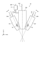
- FIG. 1 is a view showing an example of a schematic configuration of the layered manufacturing apparatus of the first embodiment.
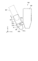
- FIG. 2 is a side view showing an example of a schematic configuration of the nozzle of the first embodiment.
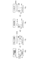
- FIG. 3 is explanatory drawing in which an example of the procedure of the modeling process (manufacturing method) by the lamination-modeling apparatus of 1st Embodiment was shown.
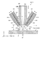
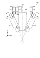
- FIG. 4 is a schematic cross-sectional view of an example of the nozzle according to the first embodiment, in which the powder of the material is supplied in the first direction.
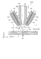
- FIG. 5 is a schematic cross-sectional view of an example of the nozzle of the first embodiment, showing a state in which powder of material is supplied in a second direction.
- FIG. 1 is a view showing an example of a schematic configuration of the layered manufacturing apparatus of the first embodiment.
- FIG. 2 is a side view showing an example of a schematic configuration of the nozzle of the first embodiment.
- FIG. 3 is explanatory drawing in which an example of
- FIG. 6 is a side view showing an example of a schematic configuration of a part of a modified nozzle.
- FIG. 7 is a side view showing an example of a schematic configuration of a nozzle according to the second embodiment.
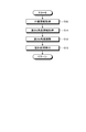
- FIG. 8 is a flow chart showing an example of the procedure of the modeling process (manufacturing method) by the layered modeling apparatus of the second embodiment.
- the layered modeling apparatus 1 includes a processing tank 11, a stage 12, a moving device 13, a nozzle device 14, an optical device 15, a measuring device 16, a control device 17 and the like.
- the layered manufacturing apparatus 1 models the layered molded article 100 having a predetermined shape by layering the material 121 supplied by the nozzle device 14 on the target object 110 disposed on the stage 12.
- the object 110 is an object to which the material 121 is supplied by the nozzle device 14 and includes a base 110a and a layer 110b. A plurality of layers 110b are stacked on the top surface of the base 110a.
- the material 121 is a powdered metal material, a resin material, or the like. One or more materials 121 may be used for shaping.
- the main chamber 21 is provided with an air inlet 21a and an air outlet 21b.
- an inert gas such as nitrogen or argon is supplied into the main chamber 21 through the air supply port 21a.
- the exhaust device By the operation of the exhaust device (not shown), the gas in the main chamber 21 is discharged from the main chamber 21 via the exhaust port 21 b.
- a transfer device (not shown) is provided in the main chamber 21 .
- a transfer device 24 is provided from the main chamber 21 to the sub chamber 22.
- the transfer device delivers the layered object 100 processed in the main chamber 21 to the transfer device 24.
- the transfer device 24 transfers the layered object 100 transferred from the transfer device into the sub chamber 22. That is, the laminate-molded article 100 processed in the main chamber 21 is accommodated in the sub-chamber 22. After the layered object 100 is accommodated in the sub chamber 22, the door 23 is closed, and the sub chamber 22 and the main chamber 21 are separated.
- a stage 12 In the main chamber 21, a stage 12, a moving device 13, a part of the nozzle device 14, a measuring device 16 and the like are provided.
- Stage 12 supports object 110.
- the moving device 13 (first moving mechanism) can move the stage 12 in three axial directions orthogonal to each other.
- the nozzle device 14 supplies the material 121 to the object 110 positioned on the stage 12. Further, the nozzle 33 of the nozzle device 14 irradiates the target object 110 positioned on the stage 12 with the laser beam 200.
- the nozzle device 14 can supply the plurality of materials 121 in parallel, and can selectively supply one of the plurality of materials 121. Further, the nozzle 33 irradiates the laser light 200 in parallel with the supply of the material 121.
- the laser beam 200 is an example of an energy ray. Note that energy rays other than laser light may be used.
- the energy beam may be any material that can melt the material, such as a laser beam, and may be an electron beam or an electromagnetic wave in a microwave to ultraviolet region.
- the nozzle device 14 has a supply device 31, a supply device 31A, a nozzle 33, a supply pipe 34, and the like.
- the material 121 is fed from the feeding device 31 to the nozzle 33 through the feeding pipe 34. Further, the gas is sent from the supply device 31A to the nozzle 33 through the supply pipe 34A.
- the supply device 31 includes a tank 31a and a supply unit 31b.
- the material 121 is accommodated in the tank 31a.
- the supply unit 31 b supplies a predetermined amount of the material 121 of the tank 31 a.
- the supply device 31 supplies a carrier gas (gas) containing the powdery material 121.
- the carrier gas is, for example, an inert gas such as nitrogen or argon.
- the supply device 31A includes a supply unit 31b.
- the supply device 31A supplies the same kind of gas as the supply device 31 supplies.
- the nozzle 33 has an emission unit 330 and one or more (for example, two) material supply units 331.
- the X direction, the Y direction, and the Z direction orthogonal to one another are defined.
- the X direction is the horizontal direction in FIG. 2
- the Y direction is the direction perpendicular to the paper surface in FIG. 2
- the Z direction is the vertical direction in FIG.
- the top surfaces of the stage 12, the laminate-molded article 100, the object 110, the base 110a, and the layer 110b extend substantially along the planes of the X direction and the Y direction.
- the nozzle 33 and the stage 12 move relative to each other, and the material along the plane in the X direction and the Y direction 121 layers 110 b are formed. Then, the layers 110b of the material 121 are sequentially stacked in the Z direction, whereby the three-dimensional layered object 100 is formed.
- the X direction and the Y direction may be referred to as a horizontal direction, a horizontal direction, or the like.
- the Z direction may be referred to as the vertical direction, the vertical direction, the height direction, the thickness direction, the vertical direction or the like.
- the emitting unit 330 is connected to the optical system 42 via the cable 210.
- the laser beam 200 is emitted from the emission unit 330 toward the modeling position.
- the powder of the material 121 is supplied to each of the material supply portions 331 from the supply device 31 via the supply pipe 34, and the gas is supplied from the supply device 31A via the air supply pipe 34A. From the material supply unit 331, the material is supplied toward the modeling position, and the gas is supplied separately from the material.
- the gas supplied separately from the material functions as a shield gas.
- the material supply unit 331 is supported by the emission unit 330 so as to be rotatable around the rotation center Ax.
- the axial direction of the rotation center Ax is set, for example, to a direction along a plane orthogonal to the emission direction of the laser beam 200, and the material supply portion 331 rotates to supply the powder of the material 121 (aperture portion 333).
- the axial direction (see FIG. 4), the opening direction, and the Z direction) are set to change along the optical path of the laser beam 200 in a state of intersecting the optical path.
- the rotation angle of the material supply unit 331 may be configured to be set manually, or may be configured to change automatically (electrically).
- the aspect of the movable support of the material supply part 331 regarding the change of the direction to which the powder of the material 121 is supplied is not limited to the structure of this embodiment,
- the material supply part 331 can slide to the radiation
- the material supply unit 331 may be supported so as to be movable along the emission direction of the laser beam 200 (vertical direction in FIG. 2).
- the emitting unit 330 is an example of a support unit.
- the moving device 71 can change the position of the nozzle 33.
- the movement device 71 changes the position of the nozzle 33 along the emission direction of the laser beam 200, thereby changing the distance between the nozzle 33 and the shaping position.
- the moving device 71 is connected to the control device 17 via a signal line 220.
- the moving device 71 can move the nozzle 33 in the vertical direction in FIG.
- the moving device 71 can be configured to include, for example, a linear actuator, a motor, a link mechanism, and the like.
- the optical device 15 includes a light source 41 and an optical system 42.
- the light source 41 has an oscillating element (not shown), and emits the laser beam 200 by oscillation of the oscillating element.
- the light source 41 can change the power density of the emitted laser beam.
- the light source 41 is connected to the optical system 42 via a cable 210.
- the laser beam 200 emitted from the light source 41 passes through the optical system 42 and enters the nozzle 33.
- the nozzle 33 irradiates the laser beam 200 onto the object 110 or the material 121 ejected toward the object 110.
- the optical system 42 includes a first lens 51, a second lens 52, a third lens 53, a fourth lens 54, a galvano scanner 55, and the like.
- the first lens 51, the second lens 52, the third lens 53, and the fourth lens 54 are fixed.
- the optical system 42 is a direction (for example, an orthogonal direction) in which the first lens 51, the second lens 52, the third lens 53, and the fourth lens 54 cross the two axial directions, specifically, the optical path.
- a movable adjustment device is a direction (for example, an orthogonal direction) in which the first lens 51, the second lens 52, the third lens 53, and the fourth lens 54 cross the two axial directions, specifically, the optical path.
- a movable adjustment device for example, an orthogonal direction
- the first lens 51 converts the laser beam 200 incident through the cable 210 into parallel light.
- the converted laser beam 200 enters the galvano scanner 55.
- the second lens 52 converges the laser beam 200 emitted from the galvano scanner 55.
- the laser beam 200 converged by the second lens 52 passes through the cable 210 and reaches the nozzle 33.
- the third lens 53 converges the laser beam 200 emitted from the galvano scanner 55.
- the laser beam 200 converged by the third lens 53 is irradiated onto the object 110.
- the fourth lens 54 converges the laser beam 200 emitted from the galvano scanner 55.
- the laser beam 200 converged by the fourth lens 54 is irradiated onto the object 110.
- the galvano scanner 55 divides the parallel light converted by the first lens 51 into light entering each of the second lens 52, the third lens 53, and the fourth lens 54.
- the galvano scanner 55 includes a first galvano mirror 57, a second galvano mirror 58, and a third galvano mirror 59.
- Each of the galvano mirrors 57, 58, 59 can split the light and change the tilt angle (emission angle).
- the first galvano mirror 57 allows a part of the laser beam 200 that has passed through the first lens 51 to pass, and emits the passed laser beam 200 to the second galvano mirror 58.
- the first galvano mirror 57 reflects the other part of the laser beam 200 and emits the reflected laser beam 200 to the fourth lens 54.
- the first galvano mirror 57 changes the irradiation position of the laser beam 200 that has passed through the fourth lens 54 according to the tilt angle.
- the second galvano mirror 58 allows a part of the laser beam 200 that has passed through the first galvano mirror 57 to pass, and emits the passed laser beam 200 to the third galvano mirror 59.
- the second galvano mirror 58 reflects the other part of the laser beam 200 and emits the reflected laser beam 200 to the third lens 53.
- the second galvanometer mirror 58 changes the irradiation position of the laser beam 200 that has passed through the third lens 53 according to the tilt angle.
- the third galvanometer mirror 59 emits a part of the laser beam 200 that has passed through the second galvanometer mirror 58 to the second lens 52.
- the first galvano mirror 57, the second galvano mirror 58, and the third lens 53 constitute a melting device 45.
- the melting device 45 heats the material 121 (123) supplied from the nozzle 33 to the object 110 by the irradiation of the laser beam 200, thereby forming the layer 110b and performing the annealing process.
- a removal device 46 for the material 121 is configured.
- the removal device 46 removes unnecessary portions formed on the base 110 a or in the layer 110 b by the irradiation of the laser beam 200.
- the removing device 46 has a predetermined shape of the laminate-molded article 100, such as an unnecessary part generated due to the scattering of the material 121 when the material 121 is supplied by the nozzle 33, an unnecessary part generated when forming the layer 110b, etc. Remove sites different from The removal device 46 emits laser light 200 having a power density sufficient to remove the unnecessary portion.
- the measuring device 16 measures the shape of the solidified layer 110 b and the shape of the layered laminate 100 formed.
- the measuring device 16 transmits information of the measured shape to the control device 17.
- the measuring device 16 includes, for example, a camera 61 and an image processing device 62.
- the image processing device 62 performs image processing based on the information measured by the camera 61.
- the measuring device 16 measures the shapes of the layer 110 b and the laminate-molded article 100 by, for example, an interference method or a light cutting method.
- the moving device 71 (first moving mechanism) can move the nozzle 33 in three axial directions orthogonal to each other.
- the control device 17 connects the moving device 13, the transport device 24, the supply device 31, the supply device 31A, the light source 41, the galvano scanner 55, the image processing device 62, and the moving device 71 (see FIG. 2) via the signal line 220. It is electrically connected.
- the controller 17 controls the moving device 13 to move the stage 12 in three axial directions.
- the control device 17 controls the transfer device 24 to transfer the shaped laminated three-dimensional object 100 to the sub chamber 22.
- the control device 17 controls the supply device 31 to adjust the presence / absence and the supply amount of the material 121.
- the control device 17 controls the light source 41 to adjust the power density of the laser beam 200 emitted from the light source 41.
- the control device 17 controls the galvano scanner 55 to adjust the tilt angles of the first galvano mirror 57, the second galvano mirror 58, and the third galvano mirror 59. Further, the control device 17 controls the position of the nozzle 33 by controlling the moving device 71.
- the control device 17 includes a storage unit 17a.
- the storage unit 17a stores data indicating the shape (reference shape) of the layered object 100 to be formed.
- the storage unit 17a also stores data indicating the heights of the nozzle 33 and the stage 12 for each of three-dimensional processing positions (each point).
- the control device 17 may have a function of selectively supplying a plurality of different materials 121 from the nozzle 33 and adjusting (changing) the ratio of the plurality of materials 121.
- the control device 17 controls the supply device 31 and the like so that the layer 110b of the material 121 is formed at the ratio based on the data indicating the ratio of each material 121 stored in the storage unit 17a.
- this function it is possible to form a graded material (gradient functional material) in which the ratio of the plurality of materials 121 changes (decreases or gradually increases) depending on the position (place) of the layered structure 100.
- the control device 17 has the ratio of the material 121 set (stored) corresponding to each position of the three-dimensional coordinates of the layered object 100,
- the control device 31 By controlling the supply device 31, it is possible to model the laminate-molded article 100 as a gradient material (gradient functional material) in which the ratio of the material 121 changes in any three-dimensional direction.
- the amount of change (rate of change) of the ratio of the material 121 per unit length can also be set variously.
- the control device 17 has a function of determining the shape of the material 121. For example, the control device 17 compares the shape of the layer 110b acquired by the measuring device 16 or the shape of the laminate-molded article 100 with the reference shape stored in the storage unit 17a to determine whether a region having a predetermined shape is not formed. Decide whether or not.
- control device 17 has a function of trimming the material 121 into a predetermined shape by removing an unnecessary portion which is determined to be a portion which is not a predetermined shape by the determination of the shape of the material 121. For example, when the material 121 is scattered and attached to a portion different from the predetermined shape, the control device 17 firstly transmits the laser beam 200 emitted from the fourth lens 54 via the first galvano mirror 57. The light source 41 is controlled to have a power density capable of evaporating the material 121. Next, the control device 17 controls the first galvano mirror 57 to irradiate the laser light 200 to the portion to evaporate the material 121.
- FIG. 3 a method of manufacturing the laminate-molded article 100 by the laminate-molding apparatus 1 will be described.
- the control device 17 controls the supply devices 31 and 31A and the like so that the material 121 is supplied from the nozzle 33 in a predetermined range, and the light source 41 and the galvano scanner 55 so that the supplied material 121 is melted by the laser light 200. Control etc.
- a predetermined amount of the melted material 123 is supplied in the range where the layer 110b on the base 110a is formed.
- the material 123 When the material 123 is jetted to the base 110a or the layer 110b, the material 123 deforms into a collection of the material 123 such as a layer or a thin film.
- the material 123 may be laminated in a granular form into a granular assembly by being cooled by a gas (gas) carrying the material 121 or by heat transfer to the assembly of the material 121.
- the control device 17 controls the light source 41, the melting device 45, and the like so that the laser light 200 is irradiated to the collection of the material 123 on the base 110a. As a result, the assembly of the material 123 is remelted into the layer 110b.
- the controller 17 controls the measuring device 16 to measure the material 123 on the base 110a on which the annealing process has been performed.
- the control device 17 compares the shape of the layer 110 b acquired by the measuring device 16 or the layered object 100 with the reference shape stored in the storage unit 17 a.
- trimming is performed.
- the control device 17 evaporates the unnecessary material 123, for example, when it is found that the material 123 on the base 110a adheres to a position different from the predetermined shape by the shape measurement and comparison with the reference shape. Control the light source 41, the removing device 46, and the like. On the other hand, the control device 17 does not perform trimming when it is found that the layer 110 b has a predetermined shape by the shape measurement and comparison with the reference shape.
- the layered manufacturing apparatus 1 forms a new layer 110b on the layer 110b.
- the additive manufacturing apparatus 1 forms the additive product 100 by repeatedly stacking the layers 110 b.
- the nozzle 33 has an emission part 330 and one or more (for example, two) material supply parts 331.
- the emitting unit 330 has an elongated shape, and is made of, for example, a material having high heat resistance such as boron nitride (ceramic material).
- the longitudinal direction (axial direction) of the emitting unit 330 is, for example, along the Z direction.
- the lateral direction (width direction) of the emitting unit 330 is, for example, along the X direction and the Y direction.
- the emitting unit 330 has, for example, a cylindrical appearance.
- the emission part 330 has the lower surface 330a, the side surface 330b, etc. as an outer surface (surface).
- the lower surface 330 a is located at a longitudinal end (lower end) of the emission unit 330 and may also be referred to as an end surface.
- the lower surface 330 a faces the stage 12, the layered object 100, the object 110, and the like.
- the lower surface 330a is formed in a planar shape.
- the side surface 330 b is located at the end in the short direction of the emission unit 330 and may be referred to as a circumferential surface.
- the side surface 330 b is formed in a cylindrical surface shape.
- An opening 332 is opened at the center of the lower surface 330 a of the emission unit 330.
- the opening 332 extends in the longitudinal direction of the emission unit 330.
- the cross section of the opening 332 along the short direction, ie, the cross section orthogonal to the longitudinal direction is circular.
- the diameter of the opening 332 may be formed to gradually decrease toward the distal end.
- the laser beam 200 is introduced into the opening 332 via a cable 210 (see FIG. 1) or the like.
- the opening 332 is a passage of the laser beam 200, and is an example of an emission port.
- the material supply unit 331 has an elongated shape, and is made of, for example, a metal material.
- the longitudinal direction (axial direction) of the material supply portion 331 is, for example, along the direction (diagonal direction) intersecting with the XY plane and the Z direction.
- the material supply portion 331 has a cylindrical appearance with a tapered portion.
- the material supply part 331 has the lower surface 331a, the side surface 331b, etc. as an outer surface (surface).
- the lower surface 331 a is located at a longitudinal end (lower end) of the material supply portion 331 and may also be referred to as an end face.
- the lower surface 331 a faces the stage 12, the layered object 100, the object 110, and the like.
- the lower surface 331 a is formed in a planar shape.
- the side surface 331 b is located at the short end of the material supply portion 331 and may also be referred to as a circumferential surface.
- the side surface 331 b is formed in a cylindrical surface shape.
- Openings 333 and 334 are opened in the lower surface 331 a of the material supply unit 331.
- the openings 333 and 334 respectively extend in parallel with each other along the longitudinal direction of the material supply portion 331.
- the opening 333 is located on the center side (central axis side) of the emission unit 330 than the opening 334.
- the cross sections of the openings 333 and 334 along the short direction, that is, the cross sections orthogonal to the longitudinal direction are circular.
- the supply device 31 is connected to the opening 333 via a supply pipe 34 (see FIG. 1) and the like.
- the opening 333 is a passage of the powder of the material 121 supplied to the processing region (the forming position Ps).
- the opening portion 334 is connected to the supply device 31A through the supply pipe 34A (see FIG. 1) and the like.
- the opening 334 is a passage for gas supplied to the processing region.
- the gas supplied from the opening 334 is used, for example, as a shield gas.
- the cross section of the opening 334 along the short direction may have a shape (for example, an arc shape, a C shape, or the like) surrounding the opening 333 from the opposite side to the opening 332.
- the laser beam 200 (optical path) emitted from the emission unit 330 toward the object 110 is focused toward the object 110. Therefore, by changing the distance between the nozzle 33 and the object 110 (the distance in the Z direction), that is, the position of the nozzle 33 in the Z direction, the light diameter D1 of the laser beam 200 at the modeling position Ps (irradiation position) D2 can be changed.
- the light diameter of the laser beam 200 is the smallest in the most condensed state, and from this state, the distance between the nozzle 33 and the object 110 increases as the distance between the nozzle 33 and the object 110 increases, and the distance between the nozzle 33 and the object 110 decreases. It becomes so big.
- FIG. 4 shows that the nozzle 33 is positioned at the position P1
- FIG. 5 shows that the nozzle 33 is positioned at a position P2 farther from the surface of the object 110 than the position P1.
- the distance H2 between the lower surface 330a of the emission unit 330 and the modeling position Ps (the surface of the object 110) in the state where the nozzle 33 is positioned at the position P2 (FIG. 5) is the position P1 (FIG. 4). It is larger than the distance H1 in the positioned state (H2> H1).
- the light diameter D1 at the shaping position Ps of the laser beam 200 in the state in which the nozzle 33 is positioned at the position P1 (FIG.
- the layered manufacturing apparatus 1 is more likely to change the position of the nozzle 33, for example, as shown in FIG. 4 for a portion (modeling position Ps) where modeling with higher accuracy is required.
- the shaping process can be performed with a smaller light diameter D1, and for a portion (modeling position Ps) where more rapid shaping is required, as shown in FIG. 5, the shaping process can be performed with a larger light diameter D2.
- the powder of the material 121 from the material supply unit 331 is The light is obliquely supplied toward the optical path of the laser beam 200.
- the posture (angle) of the material supply unit 331 with respect to the emission unit 330 is fixed (constant)
- the direction (direction) of the powder of the material 121 supplied from the material supply unit 331 remains unchanged. Therefore, the distance from the lower surface 330 a of the emitting unit 330 to the supply position of the powder of the material 121 does not change.
- the material supply unit 331 of the present embodiment is configured such that the direction (direction) to which the powder of the material 121 is supplied can be changed. As shown in FIGS. 4 and 5, when the nozzle 33 is positioned at the position P1 (FIG. 4), the angle .alpha.1 between the emitting portion 330 and the material supply portion 331 is the nozzle 33 at the position P2 (FIG.
- the angle ⁇ 2 in the positioned state is larger than the angle ⁇ 2 in the positioned state.
- the angle ⁇ 1 and ⁇ 2 (posture) of the material supply portion 331 in accordance with the position of the nozzle 33, the direction in which the powder of the material 121 is supplied from the opening 333 is the modeling position Ps. It can be understood that it is possible to suppress the displacement.
- the posture (angle) of the material supply unit 331 with respect to the emission unit 330 is fixed.
- the posture of the material supply portion 331 can be fixed using a fixing tool (a coupler, for example, a screw, not shown). In this case, the posture of the material supply portion 331 can be changed (adjusted) by releasing or relaxing the fixation by the fixing tool.
- the direction in which the powder of the material 121 is supplied from the material supply unit 331 can be changed by rotating (moving) the material supply unit 331. Therefore, for example, the powder of the material 121 is likely to be supplied more reliably or more efficiently.
- one nozzle 33 can be used instead of the plurality of nozzles used in the conventional device. Accordingly, advantages such as an increase in the supply efficiency of the powder of the material 121 and the smaller size of the layered manufacturing apparatus 1 can be obtained.
- the nozzle 33 has a plurality of material supply parts 331 capable of changing the direction in which the powder of the material 121 is supplied. Therefore, compared to the case where the powder of the material 121 is supplied from one material supply unit 331, for example, the powder of the material 121 can be supplied more quickly, or the unevenness (variation) of the powder of the material 121 is reduced. The advantages are obtained.
- the powder of the material 121 is supplied from the material supply unit 331 to the modeling position Ps (first modeling position) in FIG. 4 in the first direction, and the laser beam 200 from the emission unit 330 By being emitted, modeling at the modeling position Ps (first modeling position) is performed, and the material 121 from the material supply unit 331 to the modeling position Ps (second modeling position) in FIG. 5 in the second direction.
- the modeling at the modeling position Ps (second modeling position) is performed.
- the powder of the material 121 can be more reliably or efficiently supplied according to the modeling position Ps.
- the nozzle 33A of this modification shown in FIG. 6 has the same configuration as that of the above embodiment. Therefore, the same result (effect) based on the same composition as the above-mentioned embodiment is obtained also in this modification.
- the nozzle 33 ⁇ / b> A of this modification can have a plurality of material supply units 331.
- the material supply unit 331 is detachably supported by the emission unit 330 (support unit). Specifically, a tapered surface 331 c is formed at the end of the side surface 331 b of the material supply portion 331.
- the emission unit 330 is provided with a holder 335 for detachably supporting the material supply unit 331.
- the holder 335 has an arm portion 335a and a movable portion 335b.
- the arm part 335 a protrudes from the emitting part 330.
- the arm part 335 a is fixed to the emitting part 330.
- the movable portion 335b is rotatably supported by the arm portion 335a around the rotation center Ax.
- the axial direction of the rotation center Ax is set to, for example, a direction along a plane orthogonal to the emission direction of the laser beam 200, and the material supply portion 331 mounted on the movable portion 335b together with the movable portion 335b rotates.
- the supply direction (the axial direction of the opening 333, the opening direction, the Z direction) of the powder of the material 121 is set to change along the optical path in a state where it intersects the optical path of the laser beam 200.
- the movable portion 335b is fixed to the emission portion 330, for example, in a set posture (angle).
- the movable portion 335 b is formed in an annular shape (ring shape), and has a mortar-shaped support surface 335 c (inner surface) in the ring.
- the support surface 335 c has a shape (curvature radius, inclination, etc.) corresponding to the tapered surface 331 c provided in the material supply portion 331.
- the material supply portion 331 is inserted into the movable portion 335b from the upper side of FIG. 6 toward the lower side of FIG. 6 to a position where the support surface 335c contacts the tapered surface 331c.
- the movable portion 335 b is fixed (coupled) by, for example, a screw (not shown).
- the material supply portion 331 can be removed from the movable portion 335 b by releasing the fixing by the fixing tool.
- the angle between the arm portion 335a and the movable portion 335b may also be fixed by fixing the fixing tool.
- the material supply part 331 can be replaced more easily, for example, by comprising the material supply part 331 so that attachment or detachment is possible to the output part 330 (support part).
- the holder 335 is an example of a support.
- the structure made detachable is not limited to the said modification.
- the nozzle 33B of this modification has the same configuration as that of the above-described embodiment and modification. Therefore, the same result (effect) based on the same composition as the above-mentioned embodiment and modification is obtained also in this embodiment.
- the nozzle 33 ⁇ / b> B of the present embodiment is provided with a moving device 81 that changes the posture of the material supply unit 331.
- the moving device 81 is electrically connected to the control device 17 (see FIG. 1) via a signal line 220.
- the moving device 81 can be configured to include, for example, a linear actuator, a motor, a link mechanism, and the like.
- the control device 17 controls the moving device 81 such that the material supply unit 331 has a desired attitude.
- the control device 17 can control the control device 17 so that the posture of the material supply unit 331 does not change (is maintained) during the modeling process.
- Information (data) used for controlling the attitude of the moving device 81 is stored in the storage unit 17 a (FIG. 1) of the control device 17.
- the moving device 81 is an example of a second moving device.
- the control device 17 acquires position information of the modeling position Ps (see FIG. 4) by the nozzle 33B (S10).
- the position information may be, for example, information corresponding to three-dimensional position coordinates of the modeling position Ps, may be information for each layer 110b, or may be information for each area in the layer 110b. Good.
- the control device 17 acquires information on the height of the nozzle 33B and the angle of the material supply unit 331, which correspond to the modeling position Ps (S11).
- the information on height and angle used in S11 is stored in the storage unit 17a in association with the position information.
- the height information may be, for example, a control amount of the moving device 71
- the angle information may be, for example, a control amount of the moving device 81.
- the height information and the angle information may be data indicating the height and the angle itself, or may be information of a parameter corresponding to the height and the angle.
- the control device 17 controls the moving devices 71 and 81 based on the information on the height and the information on the angle acquired in S11 (S12).
- the nozzle 33B that is, the emitting unit 330 and the material supply unit 331 become the desired position and posture (angle) corresponding to the modeling position Ps. That is, as shown in FIGS.
- the laser beam 200 is irradiated with light diameters D1 and D2 corresponding to the modeling position Ps, and the material 121 is oriented in a direction corresponding to the modeling position Ps.
- the state where powder of is supplied is obtained.
- the light diameters D1 and D2 can be set in association with position information.
- the control device 17 executes the forming process on the forming position Ps by the nozzle 33B which has become the desired position and posture (S13).
- the layered shaping apparatus 1 forms the layer 110 b (see FIGS. 4 and 5) by performing such a process.
- the control device 17 supplies the powder of the material 121 from the material supply unit 331 in the same direction.
- the moving device 81 (second moving mechanism) is controlled to change.
- the powder of the material 121 can be supplied to the shaping position Ps more reliably or efficiently.
- the light diameter of the laser beam 200 at the modeling position Ps changes in accordance with the change in the distance between the modeling position Ps and the nozzle 33B (the material supply portion 331). Therefore, the light diameter of the laser beam 200 is easily changed relatively easily. Therefore, it is easy to increase the accuracy and efficiency of modeling. And, even in the case of having the function of changing the light diameter, the powder of the material 121 can be supplied to the modeling position Ps more reliably or more efficiently.
- the direction in which the powder of the material 121 is supplied from the material supply unit 331 changes in accordance with the change in the light diameter of the laser light 200. Therefore, it is easy to obtain a state in which the powder of the material 121 is supplied more reliably or more efficiently in response to the change of the light diameter.
- the change of the light diameter of the laser beam 200 can be realized regardless of the movement of the nozzle 33B. That is, even when the light diameter of the laser beam 200 changes without moving the nozzle 33B, the powder of the material 121 can be supplied to the modeling position Ps more reliably or more efficiently.
- the embodiment and modification of the present invention were illustrated, the above-mentioned embodiment and modification are an example, and limiting the scope of the invention is not intended. These embodiments and modifications can be implemented in other various forms, and various omissions, substitutions, combinations, and changes can be made without departing from the scope of the invention. These embodiments and modifications thereof are included in the scope and the gist of the invention, and are included in the invention described in the claims and the equivalent scope thereof.
- the present invention can be realized by other than the configuration and control (technical features) disclosed in the above-described embodiments and modifications. Furthermore, according to the present invention, at least one of various results (including effects and derivative effects) obtained by the technical features can be obtained. For example, the direction in which the powder of the material is supplied may be changed depending on the inside of the material supply unit or the change of the carrier gas without changing the posture or the position of the material supply unit.
- the layered manufacturing apparatus may be configured or used so that powder of different materials is supplied from each of a plurality of material supply units, in which case powder of materials supplied from each material supply unit
- the amount and ratio of the body may be variably controlled.
- the ratio of materials is two-dimensional or three-dimensional because each of the plurality of material supply units supplies the powder of the material in the supply amount that changes according to the three-dimensional modeling position. It can be configured such that a gradually changing gradient material (gradient functional material) is formed.
- the supply position (direction, posture, angle, position, etc. of the material supply unit) of the material by each material supply unit may be controlled to be different depending on the type of material and the flow rate (supply amount, discharge amount). Good.
Landscapes
- Engineering & Computer Science (AREA)
- Chemical & Material Sciences (AREA)
- Materials Engineering (AREA)
- Manufacturing & Machinery (AREA)
- Mechanical Engineering (AREA)
- Physics & Mathematics (AREA)
- Optics & Photonics (AREA)
- Automation & Control Theory (AREA)
- Composite Materials (AREA)
- Powder Metallurgy (AREA)
Abstract
La buse de l'appareil de fabrication par couches additives selon un mode de réalisation est pourvue de sections d'alimentation de matériau et d'une section de support. La section d'alimentation de matériau est pourvue d'un orifice d'alimentation en matériau à partir duquel une poudre du matériau est alimentée. La section de support supporte les sections d'alimentation de matériau de manière à être mobile de sorte que l'orientation dans laquelle la poudre est alimentée peut être modifiée.
Priority Applications (3)
| Application Number | Priority Date | Filing Date | Title |
|---|---|---|---|
| US15/038,630 US20160311027A1 (en) | 2014-03-18 | 2015-02-10 | Nozzle, layered object manufacturing apparatus, and method for manufacture layered object |
| CN201580010373.XA CN106061716B (zh) | 2014-03-18 | 2015-02-10 | 喷嘴、层叠造型装置及层叠造型物的制造方法 |
| DE112015001289.3T DE112015001289T5 (de) | 2014-03-18 | 2015-02-10 | Düse, Vorrichtung zur Herstellung eines Schichtobjekts und Verfahren zur Herstellung eines Schichtobjekts |
Applications Claiming Priority (2)
| Application Number | Priority Date | Filing Date | Title |
|---|---|---|---|
| JP2014055661A JP5931948B2 (ja) | 2014-03-18 | 2014-03-18 | ノズル、積層造形装置、および積層造形物の製造方法 |
| JP2014-055661 | 2014-03-18 |
Publications (1)
| Publication Number | Publication Date |
|---|---|
| WO2015141335A1 true WO2015141335A1 (fr) | 2015-09-24 |
Family
ID=54144315
Family Applications (1)
| Application Number | Title | Priority Date | Filing Date |
|---|---|---|---|
| PCT/JP2015/053680 WO2015141335A1 (fr) | 2014-03-18 | 2015-02-10 | Buse, appareil de fabrication par couches additives et procédé pour la fabrication d'un produit de fabrication par couches additives |
Country Status (5)
| Country | Link |
|---|---|
| US (1) | US20160311027A1 (fr) |
| JP (1) | JP5931948B2 (fr) |
| CN (1) | CN106061716B (fr) |
| DE (1) | DE112015001289T5 (fr) |
| WO (1) | WO2015141335A1 (fr) |
Cited By (3)
| Publication number | Priority date | Publication date | Assignee | Title |
|---|---|---|---|---|
| WO2017158738A1 (fr) * | 2016-03-15 | 2017-09-21 | 技術研究組合次世代3D積層造形技術総合開発機構 | Buse de traitement optique et dispositif de traitement optique |
| IT201600103310A1 (it) * | 2016-10-14 | 2018-04-14 | Prima Ind Spa | Macchina operatrice laser per la produzione additiva tramite trattamento termico laser, in particolare fusione, e relativo procedimento |
| IT201600103343A1 (it) * | 2016-10-14 | 2018-04-14 | Prima Ind Spa | Macchina operatrice laser per la produzione additiva tramite trattamento termico laser, in particolare fusione, e relativo procedimento |
Families Citing this family (25)
| Publication number | Priority date | Publication date | Assignee | Title |
|---|---|---|---|---|
| CN106794517B (zh) * | 2014-05-30 | 2020-06-23 | 普瑞玛工业股份有限公司 | 用于通过激光烧结来添加制造的激光操作机器及对应的方法 |
| JP6536199B2 (ja) * | 2015-06-16 | 2019-07-03 | セイコーエプソン株式会社 | 3次元形成装置 |
| FR3041278B1 (fr) * | 2015-09-23 | 2017-11-03 | Manutech-Usd | Systeme et procede de fabrication additive par fusion laser d'un lit de poudre |
| US20180162053A1 (en) | 2016-03-25 | 2018-06-14 | Technology Research Association For Future Additive Manufacturing | Three-dimensional laminating and shaping apparatus, control method of three-dimensional laminating and shaping apparatus, and control program of three-dimensional laminating and shaping apparatus |
| EP3530382B1 (fr) * | 2016-10-21 | 2023-06-28 | Adira AddCreative, SA | Système d'impression tridimensionnelle |
| KR101935768B1 (ko) * | 2016-11-23 | 2019-01-08 | 창원대학교 산학협력단 | 레이저 클래딩 장치의 헤드부 |
| KR101966954B1 (ko) * | 2017-04-18 | 2019-04-09 | 한국기계연구원 | 3차원 형상 제조를 위한 분말공급장치 |
| DE102017215841A1 (de) * | 2017-09-07 | 2019-03-07 | Sauer Gmbh | Pulverdüse für eine Laserbearbeitungsmaschine |
| CN107696480B (zh) * | 2017-09-26 | 2019-04-26 | 哈尔滨工业大学 | 一种前置送粉式电子束增材制造装置 |
| US20210220948A1 (en) | 2017-12-12 | 2021-07-22 | Nikon Corporation | Processing apparatus, processing method, marking method, modeling apparatus, modeling method, computer program and recording medium |
| JP7120253B2 (ja) * | 2017-12-12 | 2022-08-17 | 株式会社ニコン | 処理装置及び処理方法、加工方法、並びに、造形装置及び造形方法 |
| JP7066131B2 (ja) * | 2018-03-07 | 2022-05-13 | 慶應義塾 | レーザ積層造形方法及びレーザ積層造形装置 |
| JP7063670B2 (ja) * | 2018-03-26 | 2022-05-09 | 技術研究組合次世代3D積層造形技術総合開発機構 | ノズルおよび積層造形装置 |
| US11577317B2 (en) | 2018-07-16 | 2023-02-14 | Massachusetts Institute Of Technology | Spatial porosity and composition control in additive manufacturing |
| US11249460B2 (en) | 2018-10-19 | 2022-02-15 | Mitsubishi Electric Corporation | Numerical control device and method for controlling additive manufacturing apparatus |
| JP7321624B2 (ja) * | 2018-12-25 | 2023-08-07 | エルジー・ケム・リミテッド | 成形装置及び成形体の製造方法 |
| DE102019104781A1 (de) * | 2019-02-26 | 2020-08-27 | Trumpf Laser- Und Systemtechnik Gmbh | Verfahren und Vorrichtung zur Herstellung von dreidimensionalen Bauteilen durch selektives Verfestigen |
| CN110091503B (zh) * | 2019-03-29 | 2020-09-18 | 西北大学 | 适用于条形光斑的同轴送粉喷嘴 |
| JP7274948B2 (ja) * | 2019-06-11 | 2023-05-17 | ニデックマシンツール株式会社 | 三次元積層装置および方法 |
| JP7362306B2 (ja) * | 2019-06-11 | 2023-10-17 | ニデックマシンツール株式会社 | 三次元積層装置および方法 |
| FR3097164A1 (fr) * | 2019-06-17 | 2020-12-18 | Beam | Systeme et procede d’ajout de matiere sur une surface determinee d’une piece au moyen d’un faisceau laser oriente par une tete a balayage laser et d’une injection de poudre laterale |
| DE102019124518A1 (de) * | 2019-09-12 | 2021-03-18 | Trumpf Laser- Und Systemtechnik Gmbh | Materialabscheidungseinheit mit mehrfacher Materialfokuszone sowie Verfahren zum Auftragschweißen |
| WO2022018853A1 (fr) * | 2020-07-22 | 2022-01-27 | 株式会社ニコン | Système de traitement |
| EP4101574A1 (fr) | 2021-06-10 | 2022-12-14 | Laser Zentrum Hannover e.V. | Dispositif d'application de fusion par résistance électrique, en particulier de soudage par résistance ou de brassage par résistance, procédé d'application assistée par faisceau laser respectif d'une matière supplémentaire, ainsi qu'utilisation d'un dispositif |
| DE102021122972A1 (de) | 2021-09-06 | 2023-03-09 | Rheinisch-Westfälische Technische Hochschule (RWTH) Aachen, Körperschaft des öffentlichen Rechts | Düsenvorrichtung und Verfahren zum Laserauftragsschweißen |
Citations (5)
| Publication number | Priority date | Publication date | Assignee | Title |
|---|---|---|---|---|
| JPH09295350A (ja) * | 1996-05-01 | 1997-11-18 | Mitsubishi Heavy Ind Ltd | 立体造形方法およびその装置 |
| JP2002018967A (ja) * | 2000-07-11 | 2002-01-22 | Canon Inc | 目的物生成装置 |
| JP2005105414A (ja) * | 2003-09-11 | 2005-04-21 | Shunji Murano | ライン状均一吐出装置、霧化装置、薄膜形成装置、パターン形成装置、三次元造形装置および洗浄装置。 |
| JP2006176880A (ja) * | 2004-12-21 | 2006-07-06 | United Technol Corp <Utc> | コールドスプレープロセスおよび装置 |
| JP2013000708A (ja) * | 2011-06-21 | 2013-01-07 | Asahi Sunac Corp | 粉体塗装装置 |
Family Cites Families (37)
| Publication number | Priority date | Publication date | Assignee | Title |
|---|---|---|---|---|
| JPS6190735A (ja) * | 1984-10-09 | 1986-05-08 | Res Dev Corp Of Japan | 圧粉体の製造法並びにその製造装置 |
| JP3152326B2 (ja) * | 1993-12-24 | 2001-04-03 | 株式会社ケーネットシステムズ | 積層造形方法および積層造形装置 |
| US6596224B1 (en) * | 1996-05-24 | 2003-07-22 | Massachusetts Institute Of Technology | Jetting layers of powder and the formation of fine powder beds thereby |
| GB9611582D0 (en) * | 1996-06-04 | 1996-08-07 | Thin Film Technology Consultan | 3D printing and forming of structures |
| US6144008A (en) * | 1996-11-22 | 2000-11-07 | Rabinovich; Joshua E. | Rapid manufacturing system for metal, metal matrix composite materials and ceramics |
| JP3161362B2 (ja) * | 1997-05-01 | 2001-04-25 | 富士ゼロックス株式会社 | 微小構造体、その製造方法、その製造装置、基板および成形型 |
| US6441338B1 (en) * | 1999-04-19 | 2002-08-27 | Joshua E. Rabinovich | Rapid manufacturing of steel rule dies and other 3-dimensional products, apparatus, process and products |
| US6811744B2 (en) * | 1999-07-07 | 2004-11-02 | Optomec Design Company | Forming structures from CAD solid models |
| DE10053742C5 (de) * | 2000-10-30 | 2006-06-08 | Concept Laser Gmbh | Vorrichtung zum Sintern, Abtragen und/oder Beschriften mittels elektromagnetischer gebündelter Strahlung sowie Verfahren zum Betrieb der Vorrichtung |
| JP2003080604A (ja) * | 2001-09-10 | 2003-03-19 | Fuji Photo Film Co Ltd | 積層造形装置 |
| US7045738B1 (en) * | 2002-10-01 | 2006-05-16 | Southern Methodist University | Powder delivery system and method |
| EP1695778B1 (fr) * | 2003-12-11 | 2013-07-10 | Keijirou Yamamoto | Procede et dispositif de moulage de lamines |
| US7342195B2 (en) * | 2006-07-26 | 2008-03-11 | Honeywell International, Inc. | Customizable ion fusion formation system and process |
| GB0704753D0 (en) * | 2007-03-13 | 2007-04-18 | Airbus Uk Ltd | Preparation of a component for use in a joint |
| DE102007043146B4 (de) * | 2007-09-05 | 2013-06-06 | Fraunhofer-Gesellschaft zur Förderung der angewandten Forschung e.V. | Bearbeitungskopf mit integrierter Pulverzuführung zum Auftragsschweißen mit Laserstrahlung |
| US8425973B2 (en) * | 2007-11-29 | 2013-04-23 | 3M Innovative Properties Company | Three-dimensional fabrication |
| US8033811B2 (en) * | 2008-07-25 | 2011-10-11 | Stratasys, Inc. | Pantograph assembly for digital manufacturing system |
| US8666142B2 (en) * | 2008-11-18 | 2014-03-04 | Global Filtration Systems | System and method for manufacturing |
| EP2283932B1 (fr) * | 2008-12-11 | 2015-02-11 | Mimaki Engineering Co., Ltd. | Imprimante tridimensionnelle à jet d encre |
| JP5308845B2 (ja) * | 2009-01-29 | 2013-10-09 | 株式会社日本マイクロニクス | 金属微粒子の噴射ノズル |
| US8342833B2 (en) * | 2009-03-31 | 2013-01-01 | Microjet Technology Co., Ltd. | Three-dimensional object forming apparatus |
| US8474395B2 (en) * | 2009-09-11 | 2013-07-02 | John E. Meredith | Device for lining or repairing offset chimneys including a reticulated centering device with an upper and lower centering guide |
| EP3479933A1 (fr) * | 2009-09-17 | 2019-05-08 | Sciaky Inc. | Appareil de fabrication additive par des faisceaux d'électrons |
| AU2010318559B2 (en) * | 2009-11-13 | 2015-08-20 | Sciaky, Inc. | Electron beam layer manufacturing using scanning electron monitored closed loop control |
| JP2011158627A (ja) * | 2010-01-29 | 2011-08-18 | Fujifilm Corp | 印画用シートの製造方法、印画用シート及びプリント装置 |
| GB201005272D0 (en) * | 2010-03-30 | 2010-05-12 | Airbus Operations Ltd | Method of forming a joint |
| DE102010013732A1 (de) * | 2010-03-31 | 2011-10-06 | Voxeljet Technology Gmbh | Vorrichtung zum Herstellen dreidimensionaler Modelle |
| US9283593B2 (en) * | 2011-01-13 | 2016-03-15 | Siemens Energy, Inc. | Selective laser melting / sintering using powdered flux |
| CH705662A1 (de) * | 2011-11-04 | 2013-05-15 | Alstom Technology Ltd | Prozess zur Herstellung von Gegenständen aus einer durch Gamma-Prime-Ausscheidung verfestigten Superlegierung auf Nickelbasis durch selektives Laserschmelzen (SLM). |
| CN102554471B (zh) * | 2011-12-13 | 2014-09-03 | 西安交通大学 | 用于激光直接成形的角度可调式四管送粉喷嘴 |
| US8915728B2 (en) * | 2012-01-27 | 2014-12-23 | United Technologies Corporation | Multi-dimensional component build system and process |
| US20130287934A1 (en) * | 2012-04-30 | 2013-10-31 | Pallant Satnarine Ramsundar | Liquid Metal Digital Manufacturing System |
| US20130342592A1 (en) * | 2012-06-26 | 2013-12-26 | Apple Inc. | Inkjet printer for printing on a three-dimensional object and related apparatus and method |
| US20140054817A1 (en) * | 2012-08-24 | 2014-02-27 | Mission Street Manufacturing, Inc. | Three-dimensional printer |
| FR2998496B1 (fr) * | 2012-11-27 | 2021-01-29 | Association Pour La Rech Et Le Developpement De Methodes Et Processus Industriels Armines | Procede de fabrication additive d'une piece par fusion selective ou frittage selectif de lits de poudre a compacite optimisee par faisceau de haute energie |
| JP2014125643A (ja) * | 2012-12-25 | 2014-07-07 | Honda Motor Co Ltd | 三次元造形装置および三次元造形方法 |
| CN103060801B (zh) * | 2013-01-29 | 2014-11-05 | 西安交通大学 | 一种用于变光斑工艺的同轴送粉喷嘴 |
-
2014
- 2014-03-18 JP JP2014055661A patent/JP5931948B2/ja active Active
-
2015
- 2015-02-10 WO PCT/JP2015/053680 patent/WO2015141335A1/fr active Application Filing
- 2015-02-10 CN CN201580010373.XA patent/CN106061716B/zh active Active
- 2015-02-10 US US15/038,630 patent/US20160311027A1/en not_active Abandoned
- 2015-02-10 DE DE112015001289.3T patent/DE112015001289T5/de not_active Ceased
Patent Citations (5)
| Publication number | Priority date | Publication date | Assignee | Title |
|---|---|---|---|---|
| JPH09295350A (ja) * | 1996-05-01 | 1997-11-18 | Mitsubishi Heavy Ind Ltd | 立体造形方法およびその装置 |
| JP2002018967A (ja) * | 2000-07-11 | 2002-01-22 | Canon Inc | 目的物生成装置 |
| JP2005105414A (ja) * | 2003-09-11 | 2005-04-21 | Shunji Murano | ライン状均一吐出装置、霧化装置、薄膜形成装置、パターン形成装置、三次元造形装置および洗浄装置。 |
| JP2006176880A (ja) * | 2004-12-21 | 2006-07-06 | United Technol Corp <Utc> | コールドスプレープロセスおよび装置 |
| JP2013000708A (ja) * | 2011-06-21 | 2013-01-07 | Asahi Sunac Corp | 粉体塗装装置 |
Cited By (11)
| Publication number | Priority date | Publication date | Assignee | Title |
|---|---|---|---|---|
| WO2017158738A1 (fr) * | 2016-03-15 | 2017-09-21 | 技術研究組合次世代3D積層造形技術総合開発機構 | Buse de traitement optique et dispositif de traitement optique |
| JPWO2017158738A1 (ja) * | 2016-03-15 | 2018-03-29 | 技術研究組合次世代3D積層造形技術総合開発機構 | 光加工用ノズルおよび光加工装置 |
| US10850350B2 (en) | 2016-03-15 | 2020-12-01 | Technology Research Association For Future Additive Manufacturing | Optical processing nozzle and optical processing apparatus |
| IT201600103310A1 (it) * | 2016-10-14 | 2018-04-14 | Prima Ind Spa | Macchina operatrice laser per la produzione additiva tramite trattamento termico laser, in particolare fusione, e relativo procedimento |
| IT201600103343A1 (it) * | 2016-10-14 | 2018-04-14 | Prima Ind Spa | Macchina operatrice laser per la produzione additiva tramite trattamento termico laser, in particolare fusione, e relativo procedimento |
| WO2018069808A1 (fr) * | 2016-10-14 | 2018-04-19 | Prima Industrie S.P.A. | Machine de travail au laser pour impression 3d par traitement thermique au laser, en particulier par fusion, et procédé correspondant |
| WO2018069809A1 (fr) * | 2016-10-14 | 2018-04-19 | Prima Industrie S.P.A. | Machine de travail au laser pour une fabrication additive par traitement thermique au laser, en particulier par fusion, et procédé correspondant |
| CN110312584A (zh) * | 2016-10-14 | 2019-10-08 | 普瑞玛工业股份有限公司 | 通过激光热处理、特别是通过熔合的用于增材制造的激光操作机器以及对应方法 |
| CN110312583A (zh) * | 2016-10-14 | 2019-10-08 | 普瑞玛工业股份有限公司 | 通过激光热处理、特别是通过熔合的用于增材制造的激光操作机器以及对应方法 |
| CN110312583B (zh) * | 2016-10-14 | 2022-07-08 | 普瑞玛工业股份有限公司 | 通过激光热处理、特别是通过熔合的用于增材制造的激光操作机器以及对应方法 |
| CN110312584B (zh) * | 2016-10-14 | 2022-09-09 | 普瑞玛工业股份有限公司 | 通过激光热处理、特别是通过熔合的用于增材制造的激光操作机器以及对应方法 |
Also Published As
| Publication number | Publication date |
|---|---|
| CN106061716B (zh) | 2018-07-31 |
| CN106061716A (zh) | 2016-10-26 |
| JP2015178192A (ja) | 2015-10-08 |
| DE112015001289T5 (de) | 2016-12-29 |
| JP5931948B2 (ja) | 2016-06-08 |
| US20160311027A1 (en) | 2016-10-27 |
Similar Documents
| Publication | Publication Date | Title |
|---|---|---|
| WO2015141335A1 (fr) | Buse, appareil de fabrication par couches additives et procédé pour la fabrication d'un produit de fabrication par couches additives | |
| JP5931947B2 (ja) | ノズルおよび積層造形装置 | |
| CN110214075B (zh) | 在增材制造设备中对材料进行预热 | |
| JP6042390B2 (ja) | ノズル、積層造形装置、粉体供給方法及び積層造形方法 | |
| US10898971B2 (en) | Three-dimensional deposition device and three-dimensional deposition method | |
| US10780634B2 (en) | Nozzle, processing apparatus, and additive manufacturing apparatus | |
| JP6840581B2 (ja) | 積層造形装置、処理装置、及び積層造形方法 | |
| JP2021504581A (ja) | 重なり合う光ビームによる付加製造 | |
| US11534968B2 (en) | Nozzle and additive manufacturing apparatus | |
| US20160311059A1 (en) | Nozzle device and manufacturing method of layered object | |
| JP6017400B2 (ja) | 積層造形装置及び積層造形物の製造方法 | |
| CN112955270A (zh) | 层叠造形装置 | |
| US20180369961A1 (en) | Treatment of solidified layer | |
| WO2016147446A1 (fr) | Appareil de façonnage de stratifié et procédé de façonnage de stratifié | |
| JP6227080B2 (ja) | 積層造形装置及び積層造形物の製造方法 | |
| JP6283053B2 (ja) | 積層造形装置 | |
| CN114630721B (zh) | 层叠造形装置 | |
| US20210078102A1 (en) | Coating method and coating structure | |
| CN111201099A (zh) | 制造三维工件的设备和方法 |
Legal Events
| Date | Code | Title | Description |
|---|---|---|---|
| 121 | Ep: the epo has been informed by wipo that ep was designated in this application |
Ref document number: 15764092 Country of ref document: EP Kind code of ref document: A1 |
|
| WWE | Wipo information: entry into national phase |
Ref document number: 15038630 Country of ref document: US |
|
| WWE | Wipo information: entry into national phase |
Ref document number: 112015001289 Country of ref document: DE |
|
| 122 | Ep: pct application non-entry in european phase |
Ref document number: 15764092 Country of ref document: EP Kind code of ref document: A1 |