WO2015141335A1 - Nozzle, additive layer manufacturing apparatus, and method for manufacturing additive layer manufacturing product - Google Patents
Nozzle, additive layer manufacturing apparatus, and method for manufacturing additive layer manufacturing product Download PDFInfo
- Publication number
- WO2015141335A1 WO2015141335A1 PCT/JP2015/053680 JP2015053680W WO2015141335A1 WO 2015141335 A1 WO2015141335 A1 WO 2015141335A1 JP 2015053680 W JP2015053680 W JP 2015053680W WO 2015141335 A1 WO2015141335 A1 WO 2015141335A1
- Authority
- WO
- WIPO (PCT)
- Prior art keywords
- material supply
- powder
- nozzle
- unit
- supply unit
- Prior art date
Links
Images

Classifications
-
- B—PERFORMING OPERATIONS; TRANSPORTING
- B22—CASTING; POWDER METALLURGY
- B22F—WORKING METALLIC POWDER; MANUFACTURE OF ARTICLES FROM METALLIC POWDER; MAKING METALLIC POWDER; APPARATUS OR DEVICES SPECIALLY ADAPTED FOR METALLIC POWDER
- B22F7/00—Manufacture of composite layers, workpieces, or articles, comprising metallic powder, by sintering the powder, with or without compacting wherein at least one part is obtained by sintering or compression
- B22F7/02—Manufacture of composite layers, workpieces, or articles, comprising metallic powder, by sintering the powder, with or without compacting wherein at least one part is obtained by sintering or compression of composite layers
-
- B—PERFORMING OPERATIONS; TRANSPORTING
- B22—CASTING; POWDER METALLURGY
- B22F—WORKING METALLIC POWDER; MANUFACTURE OF ARTICLES FROM METALLIC POWDER; MAKING METALLIC POWDER; APPARATUS OR DEVICES SPECIALLY ADAPTED FOR METALLIC POWDER
- B22F10/00—Additive manufacturing of workpieces or articles from metallic powder
- B22F10/20—Direct sintering or melting
- B22F10/25—Direct deposition of metal particles, e.g. direct metal deposition [DMD] or laser engineered net shaping [LENS]
-
- B—PERFORMING OPERATIONS; TRANSPORTING
- B22—CASTING; POWDER METALLURGY
- B22F—WORKING METALLIC POWDER; MANUFACTURE OF ARTICLES FROM METALLIC POWDER; MAKING METALLIC POWDER; APPARATUS OR DEVICES SPECIALLY ADAPTED FOR METALLIC POWDER
- B22F10/00—Additive manufacturing of workpieces or articles from metallic powder
- B22F10/30—Process control
- B22F10/36—Process control of energy beam parameters
- B22F10/364—Process control of energy beam parameters for post-heating, e.g. remelting
-
- B—PERFORMING OPERATIONS; TRANSPORTING
- B22—CASTING; POWDER METALLURGY
- B22F—WORKING METALLIC POWDER; MANUFACTURE OF ARTICLES FROM METALLIC POWDER; MAKING METALLIC POWDER; APPARATUS OR DEVICES SPECIALLY ADAPTED FOR METALLIC POWDER
- B22F12/00—Apparatus or devices specially adapted for additive manufacturing; Auxiliary means for additive manufacturing; Combinations of additive manufacturing apparatus or devices with other processing apparatus or devices
- B22F12/50—Means for feeding of material, e.g. heads
- B22F12/53—Nozzles
-
- B—PERFORMING OPERATIONS; TRANSPORTING
- B29—WORKING OF PLASTICS; WORKING OF SUBSTANCES IN A PLASTIC STATE IN GENERAL
- B29C—SHAPING OR JOINING OF PLASTICS; SHAPING OF MATERIAL IN A PLASTIC STATE, NOT OTHERWISE PROVIDED FOR; AFTER-TREATMENT OF THE SHAPED PRODUCTS, e.g. REPAIRING
- B29C64/00—Additive manufacturing, i.e. manufacturing of three-dimensional [3D] objects by additive deposition, additive agglomeration or additive layering, e.g. by 3D printing, stereolithography or selective laser sintering
- B29C64/10—Processes of additive manufacturing
- B29C64/141—Processes of additive manufacturing using only solid materials
- B29C64/153—Processes of additive manufacturing using only solid materials using layers of powder being selectively joined, e.g. by selective laser sintering or melting
-
- B—PERFORMING OPERATIONS; TRANSPORTING
- B29—WORKING OF PLASTICS; WORKING OF SUBSTANCES IN A PLASTIC STATE IN GENERAL
- B29C—SHAPING OR JOINING OF PLASTICS; SHAPING OF MATERIAL IN A PLASTIC STATE, NOT OTHERWISE PROVIDED FOR; AFTER-TREATMENT OF THE SHAPED PRODUCTS, e.g. REPAIRING
- B29C64/00—Additive manufacturing, i.e. manufacturing of three-dimensional [3D] objects by additive deposition, additive agglomeration or additive layering, e.g. by 3D printing, stereolithography or selective laser sintering
- B29C64/10—Processes of additive manufacturing
- B29C64/188—Processes of additive manufacturing involving additional operations performed on the added layers, e.g. smoothing, grinding or thickness control
-
- B—PERFORMING OPERATIONS; TRANSPORTING
- B29—WORKING OF PLASTICS; WORKING OF SUBSTANCES IN A PLASTIC STATE IN GENERAL
- B29C—SHAPING OR JOINING OF PLASTICS; SHAPING OF MATERIAL IN A PLASTIC STATE, NOT OTHERWISE PROVIDED FOR; AFTER-TREATMENT OF THE SHAPED PRODUCTS, e.g. REPAIRING
- B29C64/00—Additive manufacturing, i.e. manufacturing of three-dimensional [3D] objects by additive deposition, additive agglomeration or additive layering, e.g. by 3D printing, stereolithography or selective laser sintering
- B29C64/20—Apparatus for additive manufacturing; Details thereof or accessories therefor
- B29C64/205—Means for applying layers
- B29C64/209—Heads; Nozzles
-
- B—PERFORMING OPERATIONS; TRANSPORTING
- B33—ADDITIVE MANUFACTURING TECHNOLOGY
- B33Y—ADDITIVE MANUFACTURING, i.e. MANUFACTURING OF THREE-DIMENSIONAL [3-D] OBJECTS BY ADDITIVE DEPOSITION, ADDITIVE AGGLOMERATION OR ADDITIVE LAYERING, e.g. BY 3-D PRINTING, STEREOLITHOGRAPHY OR SELECTIVE LASER SINTERING
- B33Y10/00—Processes of additive manufacturing
-
- B—PERFORMING OPERATIONS; TRANSPORTING
- B33—ADDITIVE MANUFACTURING TECHNOLOGY
- B33Y—ADDITIVE MANUFACTURING, i.e. MANUFACTURING OF THREE-DIMENSIONAL [3-D] OBJECTS BY ADDITIVE DEPOSITION, ADDITIVE AGGLOMERATION OR ADDITIVE LAYERING, e.g. BY 3-D PRINTING, STEREOLITHOGRAPHY OR SELECTIVE LASER SINTERING
- B33Y30/00—Apparatus for additive manufacturing; Details thereof or accessories therefor
-
- B—PERFORMING OPERATIONS; TRANSPORTING
- B22—CASTING; POWDER METALLURGY
- B22F—WORKING METALLIC POWDER; MANUFACTURE OF ARTICLES FROM METALLIC POWDER; MAKING METALLIC POWDER; APPARATUS OR DEVICES SPECIALLY ADAPTED FOR METALLIC POWDER
- B22F10/00—Additive manufacturing of workpieces or articles from metallic powder
- B22F10/50—Treatment of workpieces or articles during build-up, e.g. treatments applied to fused layers during build-up
-
- B—PERFORMING OPERATIONS; TRANSPORTING
- B22—CASTING; POWDER METALLURGY
- B22F—WORKING METALLIC POWDER; MANUFACTURE OF ARTICLES FROM METALLIC POWDER; MAKING METALLIC POWDER; APPARATUS OR DEVICES SPECIALLY ADAPTED FOR METALLIC POWDER
- B22F10/00—Additive manufacturing of workpieces or articles from metallic powder
- B22F10/80—Data acquisition or data processing
- B22F10/85—Data acquisition or data processing for controlling or regulating additive manufacturing processes
-
- B—PERFORMING OPERATIONS; TRANSPORTING
- B22—CASTING; POWDER METALLURGY
- B22F—WORKING METALLIC POWDER; MANUFACTURE OF ARTICLES FROM METALLIC POWDER; MAKING METALLIC POWDER; APPARATUS OR DEVICES SPECIALLY ADAPTED FOR METALLIC POWDER
- B22F12/00—Apparatus or devices specially adapted for additive manufacturing; Auxiliary means for additive manufacturing; Combinations of additive manufacturing apparatus or devices with other processing apparatus or devices
- B22F12/22—Driving means
- B22F12/226—Driving means for rotary motion
-
- B—PERFORMING OPERATIONS; TRANSPORTING
- B22—CASTING; POWDER METALLURGY
- B22F—WORKING METALLIC POWDER; MANUFACTURE OF ARTICLES FROM METALLIC POWDER; MAKING METALLIC POWDER; APPARATUS OR DEVICES SPECIALLY ADAPTED FOR METALLIC POWDER
- B22F12/00—Apparatus or devices specially adapted for additive manufacturing; Auxiliary means for additive manufacturing; Combinations of additive manufacturing apparatus or devices with other processing apparatus or devices
- B22F12/30—Platforms or substrates
- B22F12/33—Platforms or substrates translatory in the deposition plane
-
- B—PERFORMING OPERATIONS; TRANSPORTING
- B22—CASTING; POWDER METALLURGY
- B22F—WORKING METALLIC POWDER; MANUFACTURE OF ARTICLES FROM METALLIC POWDER; MAKING METALLIC POWDER; APPARATUS OR DEVICES SPECIALLY ADAPTED FOR METALLIC POWDER
- B22F12/00—Apparatus or devices specially adapted for additive manufacturing; Auxiliary means for additive manufacturing; Combinations of additive manufacturing apparatus or devices with other processing apparatus or devices
- B22F12/40—Radiation means
- B22F12/44—Radiation means characterised by the configuration of the radiation means
-
- B—PERFORMING OPERATIONS; TRANSPORTING
- B22—CASTING; POWDER METALLURGY
- B22F—WORKING METALLIC POWDER; MANUFACTURE OF ARTICLES FROM METALLIC POWDER; MAKING METALLIC POWDER; APPARATUS OR DEVICES SPECIALLY ADAPTED FOR METALLIC POWDER
- B22F12/00—Apparatus or devices specially adapted for additive manufacturing; Auxiliary means for additive manufacturing; Combinations of additive manufacturing apparatus or devices with other processing apparatus or devices
- B22F12/40—Radiation means
- B22F12/49—Scanners
-
- B—PERFORMING OPERATIONS; TRANSPORTING
- B22—CASTING; POWDER METALLURGY
- B22F—WORKING METALLIC POWDER; MANUFACTURE OF ARTICLES FROM METALLIC POWDER; MAKING METALLIC POWDER; APPARATUS OR DEVICES SPECIALLY ADAPTED FOR METALLIC POWDER
- B22F12/00—Apparatus or devices specially adapted for additive manufacturing; Auxiliary means for additive manufacturing; Combinations of additive manufacturing apparatus or devices with other processing apparatus or devices
- B22F12/70—Gas flow means
-
- B—PERFORMING OPERATIONS; TRANSPORTING
- B22—CASTING; POWDER METALLURGY
- B22F—WORKING METALLIC POWDER; MANUFACTURE OF ARTICLES FROM METALLIC POWDER; MAKING METALLIC POWDER; APPARATUS OR DEVICES SPECIALLY ADAPTED FOR METALLIC POWDER
- B22F12/00—Apparatus or devices specially adapted for additive manufacturing; Auxiliary means for additive manufacturing; Combinations of additive manufacturing apparatus or devices with other processing apparatus or devices
- B22F12/80—Plants, production lines or modules
- B22F12/82—Combination of additive manufacturing apparatus or devices with other processing apparatus or devices
- B22F12/86—Serial processing with multiple devices grouped
-
- B—PERFORMING OPERATIONS; TRANSPORTING
- B22—CASTING; POWDER METALLURGY
- B22F—WORKING METALLIC POWDER; MANUFACTURE OF ARTICLES FROM METALLIC POWDER; MAKING METALLIC POWDER; APPARATUS OR DEVICES SPECIALLY ADAPTED FOR METALLIC POWDER
- B22F12/00—Apparatus or devices specially adapted for additive manufacturing; Auxiliary means for additive manufacturing; Combinations of additive manufacturing apparatus or devices with other processing apparatus or devices
- B22F12/90—Means for process control, e.g. cameras or sensors
-
- Y—GENERAL TAGGING OF NEW TECHNOLOGICAL DEVELOPMENTS; GENERAL TAGGING OF CROSS-SECTIONAL TECHNOLOGIES SPANNING OVER SEVERAL SECTIONS OF THE IPC; TECHNICAL SUBJECTS COVERED BY FORMER USPC CROSS-REFERENCE ART COLLECTIONS [XRACs] AND DIGESTS
- Y02—TECHNOLOGIES OR APPLICATIONS FOR MITIGATION OR ADAPTATION AGAINST CLIMATE CHANGE
- Y02P—CLIMATE CHANGE MITIGATION TECHNOLOGIES IN THE PRODUCTION OR PROCESSING OF GOODS
- Y02P10/00—Technologies related to metal processing
- Y02P10/25—Process efficiency
Definitions
- Embodiments of the present invention relate to a nozzle, an additive manufacturing apparatus, and a method for producing an additive.
- the lamination modeling apparatus which forms a lamination-molded article is known.
- the lamination molding apparatus melts the powder by supplying powder of the material from the nozzle and emitting laser light to form a layer of the material, and stacks the layers to form a laminate.
- the nozzle for the layered modeling apparatus of the embodiment includes a material supply unit and a support unit.
- the material supply section is provided with a material supply port for discharging powder of the material.
- the support movably supports the material supply so as to change the direction in which the powder is discharged.
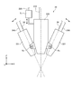
- FIG. 1 is a view showing an example of a schematic configuration of the layered manufacturing apparatus of the first embodiment.
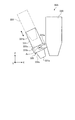
- FIG. 2 is a side view showing an example of a schematic configuration of the nozzle of the first embodiment.
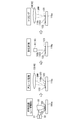
- FIG. 3 is explanatory drawing in which an example of the procedure of the modeling process (manufacturing method) by the lamination-modeling apparatus of 1st Embodiment was shown.
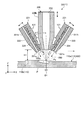
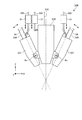
- FIG. 4 is a schematic cross-sectional view of an example of the nozzle according to the first embodiment, in which the powder of the material is supplied in the first direction.
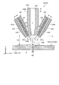
- FIG. 5 is a schematic cross-sectional view of an example of the nozzle of the first embodiment, showing a state in which powder of material is supplied in a second direction.
- FIG. 1 is a view showing an example of a schematic configuration of the layered manufacturing apparatus of the first embodiment.
- FIG. 2 is a side view showing an example of a schematic configuration of the nozzle of the first embodiment.
- FIG. 3 is explanatory drawing in which an example of
- FIG. 6 is a side view showing an example of a schematic configuration of a part of a modified nozzle.
- FIG. 7 is a side view showing an example of a schematic configuration of a nozzle according to the second embodiment.
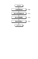
- FIG. 8 is a flow chart showing an example of the procedure of the modeling process (manufacturing method) by the layered modeling apparatus of the second embodiment.
- the layered modeling apparatus 1 includes a processing tank 11, a stage 12, a moving device 13, a nozzle device 14, an optical device 15, a measuring device 16, a control device 17 and the like.
- the layered manufacturing apparatus 1 models the layered molded article 100 having a predetermined shape by layering the material 121 supplied by the nozzle device 14 on the target object 110 disposed on the stage 12.
- the object 110 is an object to which the material 121 is supplied by the nozzle device 14 and includes a base 110a and a layer 110b. A plurality of layers 110b are stacked on the top surface of the base 110a.
- the material 121 is a powdered metal material, a resin material, or the like. One or more materials 121 may be used for shaping.
- the main chamber 21 is provided with an air inlet 21a and an air outlet 21b.
- an inert gas such as nitrogen or argon is supplied into the main chamber 21 through the air supply port 21a.
- the exhaust device By the operation of the exhaust device (not shown), the gas in the main chamber 21 is discharged from the main chamber 21 via the exhaust port 21 b.
- a transfer device (not shown) is provided in the main chamber 21 .
- a transfer device 24 is provided from the main chamber 21 to the sub chamber 22.
- the transfer device delivers the layered object 100 processed in the main chamber 21 to the transfer device 24.
- the transfer device 24 transfers the layered object 100 transferred from the transfer device into the sub chamber 22. That is, the laminate-molded article 100 processed in the main chamber 21 is accommodated in the sub-chamber 22. After the layered object 100 is accommodated in the sub chamber 22, the door 23 is closed, and the sub chamber 22 and the main chamber 21 are separated.
- a stage 12 In the main chamber 21, a stage 12, a moving device 13, a part of the nozzle device 14, a measuring device 16 and the like are provided.
- Stage 12 supports object 110.
- the moving device 13 (first moving mechanism) can move the stage 12 in three axial directions orthogonal to each other.
- the nozzle device 14 supplies the material 121 to the object 110 positioned on the stage 12. Further, the nozzle 33 of the nozzle device 14 irradiates the target object 110 positioned on the stage 12 with the laser beam 200.
- the nozzle device 14 can supply the plurality of materials 121 in parallel, and can selectively supply one of the plurality of materials 121. Further, the nozzle 33 irradiates the laser light 200 in parallel with the supply of the material 121.
- the laser beam 200 is an example of an energy ray. Note that energy rays other than laser light may be used.
- the energy beam may be any material that can melt the material, such as a laser beam, and may be an electron beam or an electromagnetic wave in a microwave to ultraviolet region.
- the nozzle device 14 has a supply device 31, a supply device 31A, a nozzle 33, a supply pipe 34, and the like.
- the material 121 is fed from the feeding device 31 to the nozzle 33 through the feeding pipe 34. Further, the gas is sent from the supply device 31A to the nozzle 33 through the supply pipe 34A.
- the supply device 31 includes a tank 31a and a supply unit 31b.
- the material 121 is accommodated in the tank 31a.
- the supply unit 31 b supplies a predetermined amount of the material 121 of the tank 31 a.
- the supply device 31 supplies a carrier gas (gas) containing the powdery material 121.
- the carrier gas is, for example, an inert gas such as nitrogen or argon.
- the supply device 31A includes a supply unit 31b.
- the supply device 31A supplies the same kind of gas as the supply device 31 supplies.
- the nozzle 33 has an emission unit 330 and one or more (for example, two) material supply units 331.
- the X direction, the Y direction, and the Z direction orthogonal to one another are defined.
- the X direction is the horizontal direction in FIG. 2
- the Y direction is the direction perpendicular to the paper surface in FIG. 2
- the Z direction is the vertical direction in FIG.
- the top surfaces of the stage 12, the laminate-molded article 100, the object 110, the base 110a, and the layer 110b extend substantially along the planes of the X direction and the Y direction.
- the nozzle 33 and the stage 12 move relative to each other, and the material along the plane in the X direction and the Y direction 121 layers 110 b are formed. Then, the layers 110b of the material 121 are sequentially stacked in the Z direction, whereby the three-dimensional layered object 100 is formed.
- the X direction and the Y direction may be referred to as a horizontal direction, a horizontal direction, or the like.
- the Z direction may be referred to as the vertical direction, the vertical direction, the height direction, the thickness direction, the vertical direction or the like.
- the emitting unit 330 is connected to the optical system 42 via the cable 210.
- the laser beam 200 is emitted from the emission unit 330 toward the modeling position.
- the powder of the material 121 is supplied to each of the material supply portions 331 from the supply device 31 via the supply pipe 34, and the gas is supplied from the supply device 31A via the air supply pipe 34A. From the material supply unit 331, the material is supplied toward the modeling position, and the gas is supplied separately from the material.
- the gas supplied separately from the material functions as a shield gas.
- the material supply unit 331 is supported by the emission unit 330 so as to be rotatable around the rotation center Ax.
- the axial direction of the rotation center Ax is set, for example, to a direction along a plane orthogonal to the emission direction of the laser beam 200, and the material supply portion 331 rotates to supply the powder of the material 121 (aperture portion 333).
- the axial direction (see FIG. 4), the opening direction, and the Z direction) are set to change along the optical path of the laser beam 200 in a state of intersecting the optical path.
- the rotation angle of the material supply unit 331 may be configured to be set manually, or may be configured to change automatically (electrically).
- the aspect of the movable support of the material supply part 331 regarding the change of the direction to which the powder of the material 121 is supplied is not limited to the structure of this embodiment,
- the material supply part 331 can slide to the radiation
- the material supply unit 331 may be supported so as to be movable along the emission direction of the laser beam 200 (vertical direction in FIG. 2).
- the emitting unit 330 is an example of a support unit.
- the moving device 71 can change the position of the nozzle 33.
- the movement device 71 changes the position of the nozzle 33 along the emission direction of the laser beam 200, thereby changing the distance between the nozzle 33 and the shaping position.
- the moving device 71 is connected to the control device 17 via a signal line 220.
- the moving device 71 can move the nozzle 33 in the vertical direction in FIG.
- the moving device 71 can be configured to include, for example, a linear actuator, a motor, a link mechanism, and the like.
- the optical device 15 includes a light source 41 and an optical system 42.
- the light source 41 has an oscillating element (not shown), and emits the laser beam 200 by oscillation of the oscillating element.
- the light source 41 can change the power density of the emitted laser beam.
- the light source 41 is connected to the optical system 42 via a cable 210.
- the laser beam 200 emitted from the light source 41 passes through the optical system 42 and enters the nozzle 33.
- the nozzle 33 irradiates the laser beam 200 onto the object 110 or the material 121 ejected toward the object 110.
- the optical system 42 includes a first lens 51, a second lens 52, a third lens 53, a fourth lens 54, a galvano scanner 55, and the like.
- the first lens 51, the second lens 52, the third lens 53, and the fourth lens 54 are fixed.
- the optical system 42 is a direction (for example, an orthogonal direction) in which the first lens 51, the second lens 52, the third lens 53, and the fourth lens 54 cross the two axial directions, specifically, the optical path.
- a movable adjustment device is a direction (for example, an orthogonal direction) in which the first lens 51, the second lens 52, the third lens 53, and the fourth lens 54 cross the two axial directions, specifically, the optical path.
- a movable adjustment device for example, an orthogonal direction
- the first lens 51 converts the laser beam 200 incident through the cable 210 into parallel light.
- the converted laser beam 200 enters the galvano scanner 55.
- the second lens 52 converges the laser beam 200 emitted from the galvano scanner 55.
- the laser beam 200 converged by the second lens 52 passes through the cable 210 and reaches the nozzle 33.
- the third lens 53 converges the laser beam 200 emitted from the galvano scanner 55.
- the laser beam 200 converged by the third lens 53 is irradiated onto the object 110.
- the fourth lens 54 converges the laser beam 200 emitted from the galvano scanner 55.
- the laser beam 200 converged by the fourth lens 54 is irradiated onto the object 110.
- the galvano scanner 55 divides the parallel light converted by the first lens 51 into light entering each of the second lens 52, the third lens 53, and the fourth lens 54.
- the galvano scanner 55 includes a first galvano mirror 57, a second galvano mirror 58, and a third galvano mirror 59.
- Each of the galvano mirrors 57, 58, 59 can split the light and change the tilt angle (emission angle).
- the first galvano mirror 57 allows a part of the laser beam 200 that has passed through the first lens 51 to pass, and emits the passed laser beam 200 to the second galvano mirror 58.
- the first galvano mirror 57 reflects the other part of the laser beam 200 and emits the reflected laser beam 200 to the fourth lens 54.
- the first galvano mirror 57 changes the irradiation position of the laser beam 200 that has passed through the fourth lens 54 according to the tilt angle.
- the second galvano mirror 58 allows a part of the laser beam 200 that has passed through the first galvano mirror 57 to pass, and emits the passed laser beam 200 to the third galvano mirror 59.
- the second galvano mirror 58 reflects the other part of the laser beam 200 and emits the reflected laser beam 200 to the third lens 53.
- the second galvanometer mirror 58 changes the irradiation position of the laser beam 200 that has passed through the third lens 53 according to the tilt angle.
- the third galvanometer mirror 59 emits a part of the laser beam 200 that has passed through the second galvanometer mirror 58 to the second lens 52.
- the first galvano mirror 57, the second galvano mirror 58, and the third lens 53 constitute a melting device 45.
- the melting device 45 heats the material 121 (123) supplied from the nozzle 33 to the object 110 by the irradiation of the laser beam 200, thereby forming the layer 110b and performing the annealing process.
- a removal device 46 for the material 121 is configured.
- the removal device 46 removes unnecessary portions formed on the base 110 a or in the layer 110 b by the irradiation of the laser beam 200.
- the removing device 46 has a predetermined shape of the laminate-molded article 100, such as an unnecessary part generated due to the scattering of the material 121 when the material 121 is supplied by the nozzle 33, an unnecessary part generated when forming the layer 110b, etc. Remove sites different from The removal device 46 emits laser light 200 having a power density sufficient to remove the unnecessary portion.
- the measuring device 16 measures the shape of the solidified layer 110 b and the shape of the layered laminate 100 formed.
- the measuring device 16 transmits information of the measured shape to the control device 17.
- the measuring device 16 includes, for example, a camera 61 and an image processing device 62.
- the image processing device 62 performs image processing based on the information measured by the camera 61.
- the measuring device 16 measures the shapes of the layer 110 b and the laminate-molded article 100 by, for example, an interference method or a light cutting method.
- the moving device 71 (first moving mechanism) can move the nozzle 33 in three axial directions orthogonal to each other.
- the control device 17 connects the moving device 13, the transport device 24, the supply device 31, the supply device 31A, the light source 41, the galvano scanner 55, the image processing device 62, and the moving device 71 (see FIG. 2) via the signal line 220. It is electrically connected.
- the controller 17 controls the moving device 13 to move the stage 12 in three axial directions.
- the control device 17 controls the transfer device 24 to transfer the shaped laminated three-dimensional object 100 to the sub chamber 22.
- the control device 17 controls the supply device 31 to adjust the presence / absence and the supply amount of the material 121.
- the control device 17 controls the light source 41 to adjust the power density of the laser beam 200 emitted from the light source 41.
- the control device 17 controls the galvano scanner 55 to adjust the tilt angles of the first galvano mirror 57, the second galvano mirror 58, and the third galvano mirror 59. Further, the control device 17 controls the position of the nozzle 33 by controlling the moving device 71.
- the control device 17 includes a storage unit 17a.
- the storage unit 17a stores data indicating the shape (reference shape) of the layered object 100 to be formed.
- the storage unit 17a also stores data indicating the heights of the nozzle 33 and the stage 12 for each of three-dimensional processing positions (each point).
- the control device 17 may have a function of selectively supplying a plurality of different materials 121 from the nozzle 33 and adjusting (changing) the ratio of the plurality of materials 121.
- the control device 17 controls the supply device 31 and the like so that the layer 110b of the material 121 is formed at the ratio based on the data indicating the ratio of each material 121 stored in the storage unit 17a.
- this function it is possible to form a graded material (gradient functional material) in which the ratio of the plurality of materials 121 changes (decreases or gradually increases) depending on the position (place) of the layered structure 100.
- the control device 17 has the ratio of the material 121 set (stored) corresponding to each position of the three-dimensional coordinates of the layered object 100,
- the control device 31 By controlling the supply device 31, it is possible to model the laminate-molded article 100 as a gradient material (gradient functional material) in which the ratio of the material 121 changes in any three-dimensional direction.
- the amount of change (rate of change) of the ratio of the material 121 per unit length can also be set variously.
- the control device 17 has a function of determining the shape of the material 121. For example, the control device 17 compares the shape of the layer 110b acquired by the measuring device 16 or the shape of the laminate-molded article 100 with the reference shape stored in the storage unit 17a to determine whether a region having a predetermined shape is not formed. Decide whether or not.
- control device 17 has a function of trimming the material 121 into a predetermined shape by removing an unnecessary portion which is determined to be a portion which is not a predetermined shape by the determination of the shape of the material 121. For example, when the material 121 is scattered and attached to a portion different from the predetermined shape, the control device 17 firstly transmits the laser beam 200 emitted from the fourth lens 54 via the first galvano mirror 57. The light source 41 is controlled to have a power density capable of evaporating the material 121. Next, the control device 17 controls the first galvano mirror 57 to irradiate the laser light 200 to the portion to evaporate the material 121.
- FIG. 3 a method of manufacturing the laminate-molded article 100 by the laminate-molding apparatus 1 will be described.
- the control device 17 controls the supply devices 31 and 31A and the like so that the material 121 is supplied from the nozzle 33 in a predetermined range, and the light source 41 and the galvano scanner 55 so that the supplied material 121 is melted by the laser light 200. Control etc.
- a predetermined amount of the melted material 123 is supplied in the range where the layer 110b on the base 110a is formed.
- the material 123 When the material 123 is jetted to the base 110a or the layer 110b, the material 123 deforms into a collection of the material 123 such as a layer or a thin film.
- the material 123 may be laminated in a granular form into a granular assembly by being cooled by a gas (gas) carrying the material 121 or by heat transfer to the assembly of the material 121.
- the control device 17 controls the light source 41, the melting device 45, and the like so that the laser light 200 is irradiated to the collection of the material 123 on the base 110a. As a result, the assembly of the material 123 is remelted into the layer 110b.
- the controller 17 controls the measuring device 16 to measure the material 123 on the base 110a on which the annealing process has been performed.
- the control device 17 compares the shape of the layer 110 b acquired by the measuring device 16 or the layered object 100 with the reference shape stored in the storage unit 17 a.
- trimming is performed.
- the control device 17 evaporates the unnecessary material 123, for example, when it is found that the material 123 on the base 110a adheres to a position different from the predetermined shape by the shape measurement and comparison with the reference shape. Control the light source 41, the removing device 46, and the like. On the other hand, the control device 17 does not perform trimming when it is found that the layer 110 b has a predetermined shape by the shape measurement and comparison with the reference shape.
- the layered manufacturing apparatus 1 forms a new layer 110b on the layer 110b.
- the additive manufacturing apparatus 1 forms the additive product 100 by repeatedly stacking the layers 110 b.
- the nozzle 33 has an emission part 330 and one or more (for example, two) material supply parts 331.
- the emitting unit 330 has an elongated shape, and is made of, for example, a material having high heat resistance such as boron nitride (ceramic material).
- the longitudinal direction (axial direction) of the emitting unit 330 is, for example, along the Z direction.
- the lateral direction (width direction) of the emitting unit 330 is, for example, along the X direction and the Y direction.
- the emitting unit 330 has, for example, a cylindrical appearance.
- the emission part 330 has the lower surface 330a, the side surface 330b, etc. as an outer surface (surface).
- the lower surface 330 a is located at a longitudinal end (lower end) of the emission unit 330 and may also be referred to as an end surface.
- the lower surface 330 a faces the stage 12, the layered object 100, the object 110, and the like.
- the lower surface 330a is formed in a planar shape.
- the side surface 330 b is located at the end in the short direction of the emission unit 330 and may be referred to as a circumferential surface.
- the side surface 330 b is formed in a cylindrical surface shape.
- An opening 332 is opened at the center of the lower surface 330 a of the emission unit 330.
- the opening 332 extends in the longitudinal direction of the emission unit 330.
- the cross section of the opening 332 along the short direction, ie, the cross section orthogonal to the longitudinal direction is circular.
- the diameter of the opening 332 may be formed to gradually decrease toward the distal end.
- the laser beam 200 is introduced into the opening 332 via a cable 210 (see FIG. 1) or the like.
- the opening 332 is a passage of the laser beam 200, and is an example of an emission port.
- the material supply unit 331 has an elongated shape, and is made of, for example, a metal material.
- the longitudinal direction (axial direction) of the material supply portion 331 is, for example, along the direction (diagonal direction) intersecting with the XY plane and the Z direction.
- the material supply portion 331 has a cylindrical appearance with a tapered portion.
- the material supply part 331 has the lower surface 331a, the side surface 331b, etc. as an outer surface (surface).
- the lower surface 331 a is located at a longitudinal end (lower end) of the material supply portion 331 and may also be referred to as an end face.
- the lower surface 331 a faces the stage 12, the layered object 100, the object 110, and the like.
- the lower surface 331 a is formed in a planar shape.
- the side surface 331 b is located at the short end of the material supply portion 331 and may also be referred to as a circumferential surface.
- the side surface 331 b is formed in a cylindrical surface shape.
- Openings 333 and 334 are opened in the lower surface 331 a of the material supply unit 331.
- the openings 333 and 334 respectively extend in parallel with each other along the longitudinal direction of the material supply portion 331.
- the opening 333 is located on the center side (central axis side) of the emission unit 330 than the opening 334.
- the cross sections of the openings 333 and 334 along the short direction, that is, the cross sections orthogonal to the longitudinal direction are circular.
- the supply device 31 is connected to the opening 333 via a supply pipe 34 (see FIG. 1) and the like.
- the opening 333 is a passage of the powder of the material 121 supplied to the processing region (the forming position Ps).
- the opening portion 334 is connected to the supply device 31A through the supply pipe 34A (see FIG. 1) and the like.
- the opening 334 is a passage for gas supplied to the processing region.
- the gas supplied from the opening 334 is used, for example, as a shield gas.
- the cross section of the opening 334 along the short direction may have a shape (for example, an arc shape, a C shape, or the like) surrounding the opening 333 from the opposite side to the opening 332.
- the laser beam 200 (optical path) emitted from the emission unit 330 toward the object 110 is focused toward the object 110. Therefore, by changing the distance between the nozzle 33 and the object 110 (the distance in the Z direction), that is, the position of the nozzle 33 in the Z direction, the light diameter D1 of the laser beam 200 at the modeling position Ps (irradiation position) D2 can be changed.
- the light diameter of the laser beam 200 is the smallest in the most condensed state, and from this state, the distance between the nozzle 33 and the object 110 increases as the distance between the nozzle 33 and the object 110 increases, and the distance between the nozzle 33 and the object 110 decreases. It becomes so big.
- FIG. 4 shows that the nozzle 33 is positioned at the position P1
- FIG. 5 shows that the nozzle 33 is positioned at a position P2 farther from the surface of the object 110 than the position P1.
- the distance H2 between the lower surface 330a of the emission unit 330 and the modeling position Ps (the surface of the object 110) in the state where the nozzle 33 is positioned at the position P2 (FIG. 5) is the position P1 (FIG. 4). It is larger than the distance H1 in the positioned state (H2> H1).
- the light diameter D1 at the shaping position Ps of the laser beam 200 in the state in which the nozzle 33 is positioned at the position P1 (FIG.
- the layered manufacturing apparatus 1 is more likely to change the position of the nozzle 33, for example, as shown in FIG. 4 for a portion (modeling position Ps) where modeling with higher accuracy is required.
- the shaping process can be performed with a smaller light diameter D1, and for a portion (modeling position Ps) where more rapid shaping is required, as shown in FIG. 5, the shaping process can be performed with a larger light diameter D2.
- the powder of the material 121 from the material supply unit 331 is The light is obliquely supplied toward the optical path of the laser beam 200.
- the posture (angle) of the material supply unit 331 with respect to the emission unit 330 is fixed (constant)
- the direction (direction) of the powder of the material 121 supplied from the material supply unit 331 remains unchanged. Therefore, the distance from the lower surface 330 a of the emitting unit 330 to the supply position of the powder of the material 121 does not change.
- the material supply unit 331 of the present embodiment is configured such that the direction (direction) to which the powder of the material 121 is supplied can be changed. As shown in FIGS. 4 and 5, when the nozzle 33 is positioned at the position P1 (FIG. 4), the angle .alpha.1 between the emitting portion 330 and the material supply portion 331 is the nozzle 33 at the position P2 (FIG.
- the angle ⁇ 2 in the positioned state is larger than the angle ⁇ 2 in the positioned state.
- the angle ⁇ 1 and ⁇ 2 (posture) of the material supply portion 331 in accordance with the position of the nozzle 33, the direction in which the powder of the material 121 is supplied from the opening 333 is the modeling position Ps. It can be understood that it is possible to suppress the displacement.
- the posture (angle) of the material supply unit 331 with respect to the emission unit 330 is fixed.
- the posture of the material supply portion 331 can be fixed using a fixing tool (a coupler, for example, a screw, not shown). In this case, the posture of the material supply portion 331 can be changed (adjusted) by releasing or relaxing the fixation by the fixing tool.
- the direction in which the powder of the material 121 is supplied from the material supply unit 331 can be changed by rotating (moving) the material supply unit 331. Therefore, for example, the powder of the material 121 is likely to be supplied more reliably or more efficiently.
- one nozzle 33 can be used instead of the plurality of nozzles used in the conventional device. Accordingly, advantages such as an increase in the supply efficiency of the powder of the material 121 and the smaller size of the layered manufacturing apparatus 1 can be obtained.
- the nozzle 33 has a plurality of material supply parts 331 capable of changing the direction in which the powder of the material 121 is supplied. Therefore, compared to the case where the powder of the material 121 is supplied from one material supply unit 331, for example, the powder of the material 121 can be supplied more quickly, or the unevenness (variation) of the powder of the material 121 is reduced. The advantages are obtained.
- the powder of the material 121 is supplied from the material supply unit 331 to the modeling position Ps (first modeling position) in FIG. 4 in the first direction, and the laser beam 200 from the emission unit 330 By being emitted, modeling at the modeling position Ps (first modeling position) is performed, and the material 121 from the material supply unit 331 to the modeling position Ps (second modeling position) in FIG. 5 in the second direction.
- the modeling at the modeling position Ps (second modeling position) is performed.
- the powder of the material 121 can be more reliably or efficiently supplied according to the modeling position Ps.
- the nozzle 33A of this modification shown in FIG. 6 has the same configuration as that of the above embodiment. Therefore, the same result (effect) based on the same composition as the above-mentioned embodiment is obtained also in this modification.
- the nozzle 33 ⁇ / b> A of this modification can have a plurality of material supply units 331.
- the material supply unit 331 is detachably supported by the emission unit 330 (support unit). Specifically, a tapered surface 331 c is formed at the end of the side surface 331 b of the material supply portion 331.
- the emission unit 330 is provided with a holder 335 for detachably supporting the material supply unit 331.
- the holder 335 has an arm portion 335a and a movable portion 335b.
- the arm part 335 a protrudes from the emitting part 330.
- the arm part 335 a is fixed to the emitting part 330.
- the movable portion 335b is rotatably supported by the arm portion 335a around the rotation center Ax.
- the axial direction of the rotation center Ax is set to, for example, a direction along a plane orthogonal to the emission direction of the laser beam 200, and the material supply portion 331 mounted on the movable portion 335b together with the movable portion 335b rotates.
- the supply direction (the axial direction of the opening 333, the opening direction, the Z direction) of the powder of the material 121 is set to change along the optical path in a state where it intersects the optical path of the laser beam 200.
- the movable portion 335b is fixed to the emission portion 330, for example, in a set posture (angle).
- the movable portion 335 b is formed in an annular shape (ring shape), and has a mortar-shaped support surface 335 c (inner surface) in the ring.
- the support surface 335 c has a shape (curvature radius, inclination, etc.) corresponding to the tapered surface 331 c provided in the material supply portion 331.
- the material supply portion 331 is inserted into the movable portion 335b from the upper side of FIG. 6 toward the lower side of FIG. 6 to a position where the support surface 335c contacts the tapered surface 331c.
- the movable portion 335 b is fixed (coupled) by, for example, a screw (not shown).
- the material supply portion 331 can be removed from the movable portion 335 b by releasing the fixing by the fixing tool.
- the angle between the arm portion 335a and the movable portion 335b may also be fixed by fixing the fixing tool.
- the material supply part 331 can be replaced more easily, for example, by comprising the material supply part 331 so that attachment or detachment is possible to the output part 330 (support part).
- the holder 335 is an example of a support.
- the structure made detachable is not limited to the said modification.
- the nozzle 33B of this modification has the same configuration as that of the above-described embodiment and modification. Therefore, the same result (effect) based on the same composition as the above-mentioned embodiment and modification is obtained also in this embodiment.
- the nozzle 33 ⁇ / b> B of the present embodiment is provided with a moving device 81 that changes the posture of the material supply unit 331.
- the moving device 81 is electrically connected to the control device 17 (see FIG. 1) via a signal line 220.
- the moving device 81 can be configured to include, for example, a linear actuator, a motor, a link mechanism, and the like.
- the control device 17 controls the moving device 81 such that the material supply unit 331 has a desired attitude.
- the control device 17 can control the control device 17 so that the posture of the material supply unit 331 does not change (is maintained) during the modeling process.
- Information (data) used for controlling the attitude of the moving device 81 is stored in the storage unit 17 a (FIG. 1) of the control device 17.
- the moving device 81 is an example of a second moving device.
- the control device 17 acquires position information of the modeling position Ps (see FIG. 4) by the nozzle 33B (S10).
- the position information may be, for example, information corresponding to three-dimensional position coordinates of the modeling position Ps, may be information for each layer 110b, or may be information for each area in the layer 110b. Good.
- the control device 17 acquires information on the height of the nozzle 33B and the angle of the material supply unit 331, which correspond to the modeling position Ps (S11).
- the information on height and angle used in S11 is stored in the storage unit 17a in association with the position information.
- the height information may be, for example, a control amount of the moving device 71
- the angle information may be, for example, a control amount of the moving device 81.
- the height information and the angle information may be data indicating the height and the angle itself, or may be information of a parameter corresponding to the height and the angle.
- the control device 17 controls the moving devices 71 and 81 based on the information on the height and the information on the angle acquired in S11 (S12).
- the nozzle 33B that is, the emitting unit 330 and the material supply unit 331 become the desired position and posture (angle) corresponding to the modeling position Ps. That is, as shown in FIGS.
- the laser beam 200 is irradiated with light diameters D1 and D2 corresponding to the modeling position Ps, and the material 121 is oriented in a direction corresponding to the modeling position Ps.
- the state where powder of is supplied is obtained.
- the light diameters D1 and D2 can be set in association with position information.
- the control device 17 executes the forming process on the forming position Ps by the nozzle 33B which has become the desired position and posture (S13).
- the layered shaping apparatus 1 forms the layer 110 b (see FIGS. 4 and 5) by performing such a process.
- the control device 17 supplies the powder of the material 121 from the material supply unit 331 in the same direction.
- the moving device 81 (second moving mechanism) is controlled to change.
- the powder of the material 121 can be supplied to the shaping position Ps more reliably or efficiently.
- the light diameter of the laser beam 200 at the modeling position Ps changes in accordance with the change in the distance between the modeling position Ps and the nozzle 33B (the material supply portion 331). Therefore, the light diameter of the laser beam 200 is easily changed relatively easily. Therefore, it is easy to increase the accuracy and efficiency of modeling. And, even in the case of having the function of changing the light diameter, the powder of the material 121 can be supplied to the modeling position Ps more reliably or more efficiently.
- the direction in which the powder of the material 121 is supplied from the material supply unit 331 changes in accordance with the change in the light diameter of the laser light 200. Therefore, it is easy to obtain a state in which the powder of the material 121 is supplied more reliably or more efficiently in response to the change of the light diameter.
- the change of the light diameter of the laser beam 200 can be realized regardless of the movement of the nozzle 33B. That is, even when the light diameter of the laser beam 200 changes without moving the nozzle 33B, the powder of the material 121 can be supplied to the modeling position Ps more reliably or more efficiently.
- the embodiment and modification of the present invention were illustrated, the above-mentioned embodiment and modification are an example, and limiting the scope of the invention is not intended. These embodiments and modifications can be implemented in other various forms, and various omissions, substitutions, combinations, and changes can be made without departing from the scope of the invention. These embodiments and modifications thereof are included in the scope and the gist of the invention, and are included in the invention described in the claims and the equivalent scope thereof.
- the present invention can be realized by other than the configuration and control (technical features) disclosed in the above-described embodiments and modifications. Furthermore, according to the present invention, at least one of various results (including effects and derivative effects) obtained by the technical features can be obtained. For example, the direction in which the powder of the material is supplied may be changed depending on the inside of the material supply unit or the change of the carrier gas without changing the posture or the position of the material supply unit.
- the layered manufacturing apparatus may be configured or used so that powder of different materials is supplied from each of a plurality of material supply units, in which case powder of materials supplied from each material supply unit
- the amount and ratio of the body may be variably controlled.
- the ratio of materials is two-dimensional or three-dimensional because each of the plurality of material supply units supplies the powder of the material in the supply amount that changes according to the three-dimensional modeling position. It can be configured such that a gradually changing gradient material (gradient functional material) is formed.
- the supply position (direction, posture, angle, position, etc. of the material supply unit) of the material by each material supply unit may be controlled to be different depending on the type of material and the flow rate (supply amount, discharge amount). Good.
Abstract
The nozzle of the additive layer manufacturing apparatus according to an embodiment is provided with material-supplying sections and a support section. The material-supplying section is provided with a material supply port from which a powder of the material is supplied. The support section supports the material-supplying sections so as to be movable so that the orientation in which powder is supplied can be changed.
Description
本発明の実施形態は、ノズル、積層造形装置、および積層造形物の製造方法に関する。
Embodiments of the present invention relate to a nozzle, an additive manufacturing apparatus, and a method for producing an additive.
従来、積層造形物を形成する積層造形装置が知られている。積層造形装置は、ノズルから材料の粉体を供給するとともにレーザ光を出射することにより粉体を溶融させて材料の層を形成し、当該層を積み重ねることにより積層造形物を形成する。
DESCRIPTION OF RELATED ART Conventionally, the lamination modeling apparatus which forms a lamination-molded article is known. The lamination molding apparatus melts the powder by supplying powder of the material from the nozzle and emitting laser light to form a layer of the material, and stacks the layers to form a laminate.
この種の装置では、例えば、造形位置への材料の供給をより確実にあるいはより効率よく行うことができれば、有意義である。
In this type of apparatus, for example, it is significant if the supply of the material to the shaping position can be performed more reliably or more efficiently.
実施形態の積層造形装置用のノズルは、材料供給部と、支持部と、を備える。材料供給部には、材料の粉体を吐出する材料供給口が設けられる。支持部は、粉体を吐出する向きを変えられるよう材料供給部を移動可能に支持する。
The nozzle for the layered modeling apparatus of the embodiment includes a material supply unit and a support unit. The material supply section is provided with a material supply port for discharging powder of the material. The support movably supports the material supply so as to change the direction in which the powder is discharged.
以下、本発明の例示的な実施形態および変形例が開示される。以下に示される実施形態および変形例の構成や制御(技術的特徴)、ならびに当該構成や制御によってもたらされる作用および結果(効果)は、一例である。
In the following, exemplary embodiments and variants of the invention are disclosed. Configurations and controls (technical features) of the embodiments and modifications described below, and operations and results (effects) provided by the configurations and controls are examples.
また、以下に開示される実施形態や変形例には、同様の構成要素が含まれる。以下では、同様の構成要素には共通の符号が付与されるとともに、重複する説明が省略される。
In addition, the same constituent elements are included in the embodiments and modifications disclosed below. Below, while a common code | symbol is provided to the same component, the overlapping description is abbreviate | omitted.
<第1実施形態>
図1に示されるように、積層造形装置1は、処理槽11や、ステージ12、移動装置13、ノズル装置14、光学装置15、計測装置16、制御装置17等を備えている。 First Embodiment
As shown in FIG. 1, thelayered modeling apparatus 1 includes a processing tank 11, a stage 12, a moving device 13, a nozzle device 14, an optical device 15, a measuring device 16, a control device 17 and the like.
図1に示されるように、積層造形装置1は、処理槽11や、ステージ12、移動装置13、ノズル装置14、光学装置15、計測装置16、制御装置17等を備えている。 First Embodiment
As shown in FIG. 1, the
積層造形装置1は、ステージ12上に配置された対象物110に、ノズル装置14で供給される材料121を層状に積み重ねることにより、所定の形状の積層造形物100を造形する。
The layered manufacturing apparatus 1 models the layered molded article 100 having a predetermined shape by layering the material 121 supplied by the nozzle device 14 on the target object 110 disposed on the stage 12.
対象物110は、ノズル装置14によって材料121が供給される対象であって、ベース110aおよび層110bを含む。複数の層110bがベース110aの上面に積層される。材料121は、粉末状の金属材料や樹脂材料等である。造形には、一つ以上の材料121が用いられうる。
The object 110 is an object to which the material 121 is supplied by the nozzle device 14 and includes a base 110a and a layer 110b. A plurality of layers 110b are stacked on the top surface of the base 110a. The material 121 is a powdered metal material, a resin material, or the like. One or more materials 121 may be used for shaping.
処理槽11には、主室21と副室22とが設けられている。副室22は、主室21と隣接して設けられている。主室21と副室22との間には扉部23が設けられている。扉部23が開かれた場合、主室21と副室22とが連通され、扉部23が閉じられた場合、主室21が気密状態になる。
A main chamber 21 and a sub chamber 22 are provided in the processing tank 11. The sub chamber 22 is provided adjacent to the main chamber 21. A door 23 is provided between the main chamber 21 and the sub chamber 22. When the door 23 is opened, the main chamber 21 and the auxiliary chamber 22 communicate with each other, and when the door 23 is closed, the main chamber 21 becomes airtight.
主室21には、給気口21aおよび排気口21bが設けられている。給気装置(図示されず)の動作により、主室21内に給気口21aを介して窒素やアルゴン等の不活性ガスが供給される。排気装置(図示されず)の動作により、主室21から排気口21bを介して主室21内のガスが排出される。
The main chamber 21 is provided with an air inlet 21a and an air outlet 21b. By the operation of the air supply device (not shown), an inert gas such as nitrogen or argon is supplied into the main chamber 21 through the air supply port 21a. By the operation of the exhaust device (not shown), the gas in the main chamber 21 is discharged from the main chamber 21 via the exhaust port 21 b.
また、主室21内には、移送装置(図示されず)が設けられている。また、主室21から副室22にかけて、搬送装置24が設けられている。移送装置は、主室21で処理された積層造形物100を、搬送装置24に渡す。搬送装置24は、移送装置から渡された積層造形物100を副室22内に搬送する。すなわち、副室22には、主室21で処理された積層造形物100が収容される。積層造形物100が副室22に収容された後、扉部23が閉じられ、副室22と主室21とが隔絶される。
Further, in the main chamber 21, a transfer device (not shown) is provided. In addition, a transfer device 24 is provided from the main chamber 21 to the sub chamber 22. The transfer device delivers the layered object 100 processed in the main chamber 21 to the transfer device 24. The transfer device 24 transfers the layered object 100 transferred from the transfer device into the sub chamber 22. That is, the laminate-molded article 100 processed in the main chamber 21 is accommodated in the sub-chamber 22. After the layered object 100 is accommodated in the sub chamber 22, the door 23 is closed, and the sub chamber 22 and the main chamber 21 are separated.
主室21内には、ステージ12や、移動装置13、ノズル装置14の一部、計測装置16等が設けられている。
In the main chamber 21, a stage 12, a moving device 13, a part of the nozzle device 14, a measuring device 16 and the like are provided.
ステージ12は、対象物110を支持する。移動装置13(第一の移動機構)は、ステージ12を、互いに直交する3軸方向に移動することができる。
Stage 12 supports object 110. The moving device 13 (first moving mechanism) can move the stage 12 in three axial directions orthogonal to each other.
ノズル装置14は、ステージ12上に位置された対象物110に材料121を供給する。また、ノズル装置14のノズル33は、ステージ12上に位置された対象物110にレーザ光200を照射する。ノズル装置14は、複数の材料121を並行して供給することができるし、複数の材料121のうち一つを選択的に供給することができる。また、ノズル33は、材料121の供給と並行してレーザ光200を照射する。レーザ光200は、エネルギ線の一例である。なお、レーザ光以外のエネルギ線を用いてもよい。エネルギ線は、レーザ光のように材料を溶融できるものであればよく、電子ビームや、マイクロ波から紫外線領域の電磁波などであってもよい。
The nozzle device 14 supplies the material 121 to the object 110 positioned on the stage 12. Further, the nozzle 33 of the nozzle device 14 irradiates the target object 110 positioned on the stage 12 with the laser beam 200. The nozzle device 14 can supply the plurality of materials 121 in parallel, and can selectively supply one of the plurality of materials 121. Further, the nozzle 33 irradiates the laser light 200 in parallel with the supply of the material 121. The laser beam 200 is an example of an energy ray. Note that energy rays other than laser light may be used. The energy beam may be any material that can melt the material, such as a laser beam, and may be an electron beam or an electromagnetic wave in a microwave to ultraviolet region.
ノズル装置14は、供給装置31や、供給装置31A、ノズル33、供給管34等を有している。材料121は、供給装置31から供給管34を経てノズル33へ送られる。また、気体は、供給装置31Aから、供給管34Aを経てノズル33へ送られる。
The nozzle device 14 has a supply device 31, a supply device 31A, a nozzle 33, a supply pipe 34, and the like. The material 121 is fed from the feeding device 31 to the nozzle 33 through the feeding pipe 34. Further, the gas is sent from the supply device 31A to the nozzle 33 through the supply pipe 34A.
供給装置31は、タンク31aと、供給部31bと、を含む。タンク31aには、材料121が収容される。供給部31bは、タンク31aの材料121を所定量供給する。供給装置31は、粉状の材料121が含まれたキャリアガス(気体)を供給する。キャリアガスは、例えば、窒素やアルゴン等の不活性ガスである。また、供給装置31Aは、供給部31bを含む。供給装置31Aは、供給装置31が供給するのと同種のガス(気体)を供給する。
The supply device 31 includes a tank 31a and a supply unit 31b. The material 121 is accommodated in the tank 31a. The supply unit 31 b supplies a predetermined amount of the material 121 of the tank 31 a. The supply device 31 supplies a carrier gas (gas) containing the powdery material 121. The carrier gas is, for example, an inert gas such as nitrogen or argon. Further, the supply device 31A includes a supply unit 31b. The supply device 31A supplies the same kind of gas as the supply device 31 supplies.
図2にも示されるように、ノズル33は、出射部330と、一つ以上(例えば二つ)の材料供給部331と、を有する。以下では、説明の便宜上、互いに直交するX方向、Y方向、およびZ方向が規定される。X方向は、図2では左右方向であり、Y方向は、図2は紙面と垂直な方向であり、Z方向は、図2では上下方向である。ステージ12、積層造形物100、対象物110、ベース110a、および層110bの上面は、X方向とY方向との平面に略沿って広がる。積層造形装置1では、ノズル33およびステージ12のうち少なくとも一方がX方向およびY方向に移動することによりノズル33とステージ12とが相対的に移動し、X方向およびY方向の平面に沿って材料121の層110bが形成される。そして、材料121の層110bが順次Z方向に積層されることで、立体的な積層造形物100が形成される。X方向およびY方向は、水平方向や横方向等と称されうる。Z方向は、鉛直方向や、垂直方向、高さ方向、厚さ方向、縦方向等と称されうる。
As also shown in FIG. 2, the nozzle 33 has an emission unit 330 and one or more (for example, two) material supply units 331. In the following, for convenience of explanation, the X direction, the Y direction, and the Z direction orthogonal to one another are defined. The X direction is the horizontal direction in FIG. 2, the Y direction is the direction perpendicular to the paper surface in FIG. 2, and the Z direction is the vertical direction in FIG. The top surfaces of the stage 12, the laminate-molded article 100, the object 110, the base 110a, and the layer 110b extend substantially along the planes of the X direction and the Y direction. In the layered manufacturing apparatus 1, when at least one of the nozzle 33 and the stage 12 moves in the X direction and the Y direction, the nozzle 33 and the stage 12 move relative to each other, and the material along the plane in the X direction and the Y direction 121 layers 110 b are formed. Then, the layers 110b of the material 121 are sequentially stacked in the Z direction, whereby the three-dimensional layered object 100 is formed. The X direction and the Y direction may be referred to as a horizontal direction, a horizontal direction, or the like. The Z direction may be referred to as the vertical direction, the vertical direction, the height direction, the thickness direction, the vertical direction or the like.
出射部330は、ケーブル210を介して光学系42に接続されている。出射部330からは、造形位置に向けて、レーザ光200が出射される。また、材料供給部331のそれぞれには、供給装置31から供給管34を介して材料121の粉体が供給されるとともに、供給装置31Aから給気管34Aを介して気体が供給される。材料供給部331からは、造形位置に向けて材料が供給されるとともに、材料とは別に気体が供給される。材料とは別に供給される気体はシールドガスとして機能する。
The emitting unit 330 is connected to the optical system 42 via the cable 210. The laser beam 200 is emitted from the emission unit 330 toward the modeling position. Further, the powder of the material 121 is supplied to each of the material supply portions 331 from the supply device 31 via the supply pipe 34, and the gas is supplied from the supply device 31A via the air supply pipe 34A. From the material supply unit 331, the material is supplied toward the modeling position, and the gas is supplied separately from the material. The gas supplied separately from the material functions as a shield gas.
また、材料供給部331は、出射部330に、それぞれ、回転中心Ax回りに回動可能に支持されている。材料供給部331が回動することにより、材料121の粉体が供給される向き(角度、方向)が変化する。回転中心Axの軸方向は、例えば、レーザ光200の出射方向と直交する面に沿う方向に設定され、材料供給部331が回動することにより、材料121の粉体の供給方向(開口部333(図4参照)の軸方向、開口方向、Z方向)が、レーザ光200の光路と交わった状態で当該光路に沿って変化するよう、設定される。材料供給部331の回動角度は、手動で設定されるように構成されてもよいし、自動的(電気的に)に変化するように構成されてもよい。なお、材料121の粉体が供給される向きの変化に関する材料供給部331の可動支持の態様は、本実施形態の構造には限定されず、例えば、材料供給部331は出射部330にスライド可能、すなわち移動可能に、支持されてもよい。一例としては、材料供給部331は、レーザ光200の出射方向(図2の上下方向)に沿って移動可能に支持されてもよい。出射部330は、支持部の一例である。
In addition, the material supply unit 331 is supported by the emission unit 330 so as to be rotatable around the rotation center Ax. By rotating the material supply unit 331, the direction (angle, direction) in which the powder of the material 121 is supplied changes. The axial direction of the rotation center Ax is set, for example, to a direction along a plane orthogonal to the emission direction of the laser beam 200, and the material supply portion 331 rotates to supply the powder of the material 121 (aperture portion 333). The axial direction (see FIG. 4), the opening direction, and the Z direction) are set to change along the optical path of the laser beam 200 in a state of intersecting the optical path. The rotation angle of the material supply unit 331 may be configured to be set manually, or may be configured to change automatically (electrically). In addition, the aspect of the movable support of the material supply part 331 regarding the change of the direction to which the powder of the material 121 is supplied is not limited to the structure of this embodiment, For example, the material supply part 331 can slide to the radiation | emission part 330 That is, movably supported. As one example, the material supply unit 331 may be supported so as to be movable along the emission direction of the laser beam 200 (vertical direction in FIG. 2). The emitting unit 330 is an example of a support unit.
移動装置71は、ノズル33の位置を変化させることができる。移動装置71により、ノズル33の位置が、レーザ光200の出射方向に沿って変化することで、ノズル33と造形位置との距離が変化する。移動装置71は、信号線220を介して制御装置17に接続されている。移動装置71は、ノズル33を図2の上下方向に動かすことができる。移動装置71は、例えば、リニアアクチュエータや、モータ、リンク機構等を有して構成されうる。
The moving device 71 can change the position of the nozzle 33. The movement device 71 changes the position of the nozzle 33 along the emission direction of the laser beam 200, thereby changing the distance between the nozzle 33 and the shaping position. The moving device 71 is connected to the control device 17 via a signal line 220. The moving device 71 can move the nozzle 33 in the vertical direction in FIG. The moving device 71 can be configured to include, for example, a linear actuator, a motor, a link mechanism, and the like.
また、図1に示されるように、光学装置15は、光源41と、光学系42と、を備えている。光源41は、発振素子(図示されず)を有し、発振素子の発振によりレーザ光200を出射する。光源41は、出射するレーザ光のパワー密度を変更することができる。
Further, as shown in FIG. 1, the optical device 15 includes a light source 41 and an optical system 42. The light source 41 has an oscillating element (not shown), and emits the laser beam 200 by oscillation of the oscillating element. The light source 41 can change the power density of the emitted laser beam.
光源41は、ケーブル210を介して光学系42に接続されている。光源41から出射されたレーザ光200は、光学系42を経てノズル33に入る。ノズル33は、レーザ光200を、対象物110や、対象物110に向けて噴射された材料121に照射する。
The light source 41 is connected to the optical system 42 via a cable 210. The laser beam 200 emitted from the light source 41 passes through the optical system 42 and enters the nozzle 33. The nozzle 33 irradiates the laser beam 200 onto the object 110 or the material 121 ejected toward the object 110.
光学系42は、具体的には、第1レンズ51や、第2レンズ52、第3レンズ53、第4レンズ54、ガルバノスキャナ55等を、備えている。第1レンズ51、第2レンズ52、第3レンズ53、および第4レンズ54は、固定されている。なお、光学系42は、第1レンズ51、第2レンズ52、第3レンズ53、および第4レンズ54を、2軸方向、具体的には光路に対して交叉する方向(例えば、直交方向)に移動可能な調整装置を備えてもよい。
Specifically, the optical system 42 includes a first lens 51, a second lens 52, a third lens 53, a fourth lens 54, a galvano scanner 55, and the like. The first lens 51, the second lens 52, the third lens 53, and the fourth lens 54 are fixed. The optical system 42 is a direction (for example, an orthogonal direction) in which the first lens 51, the second lens 52, the third lens 53, and the fourth lens 54 cross the two axial directions, specifically, the optical path. And a movable adjustment device.
第1レンズ51は、ケーブル210を介して入射されたレーザ光200を平行光に変換する。変換されたレーザ光200は、ガルバノスキャナ55に入射する。
The first lens 51 converts the laser beam 200 incident through the cable 210 into parallel light. The converted laser beam 200 enters the galvano scanner 55.
第2レンズ52は、ガルバノスキャナ55から出射されたレーザ光200を収束する。第2レンズ52で収束されたレーザ光200は、ケーブル210を経てノズル33に至る。
The second lens 52 converges the laser beam 200 emitted from the galvano scanner 55. The laser beam 200 converged by the second lens 52 passes through the cable 210 and reaches the nozzle 33.
第3レンズ53は、ガルバノスキャナ55から出射されたレーザ光200を収束する。第3レンズ53で収束されたレーザ光200は、対象物110上に照射される。
The third lens 53 converges the laser beam 200 emitted from the galvano scanner 55. The laser beam 200 converged by the third lens 53 is irradiated onto the object 110.
第4レンズ54は、ガルバノスキャナ55から出射されたレーザ光200を収束する。第4レンズ54で収束されたレーザ光200は、対象物110上に照射される。
The fourth lens 54 converges the laser beam 200 emitted from the galvano scanner 55. The laser beam 200 converged by the fourth lens 54 is irradiated onto the object 110.
ガルバノスキャナ55は、第1レンズ51で変換された平行光を、第2レンズ52、第3レンズ53、および第4レンズ54のそれぞれに入る光に分ける。ガルバノスキャナ55は、第1ガルバノミラー57と、第2ガルバノミラー58と、第3ガルバノミラー59と、を備えている。各ガルバノミラー57,58,59は、光を分けるとともに、傾斜角度(出射角度)を変化することができる。
The galvano scanner 55 divides the parallel light converted by the first lens 51 into light entering each of the second lens 52, the third lens 53, and the fourth lens 54. The galvano scanner 55 includes a first galvano mirror 57, a second galvano mirror 58, and a third galvano mirror 59. Each of the galvano mirrors 57, 58, 59 can split the light and change the tilt angle (emission angle).
第1ガルバノミラー57は、第1レンズ51を通過したレーザ光200の一部を通過させ、通過したレーザ光200を第2ガルバノミラー58に出射する。また、第1ガルバノミラー57は、レーザ光200の他部を反射させ、反射したレーザ光200を第4レンズ54に出射する。第1ガルバノミラー57は、その傾斜角度によって、第4レンズ54を通過したレーザ光200の照射位置を変化させる。
The first galvano mirror 57 allows a part of the laser beam 200 that has passed through the first lens 51 to pass, and emits the passed laser beam 200 to the second galvano mirror 58. The first galvano mirror 57 reflects the other part of the laser beam 200 and emits the reflected laser beam 200 to the fourth lens 54. The first galvano mirror 57 changes the irradiation position of the laser beam 200 that has passed through the fourth lens 54 according to the tilt angle.
第2ガルバノミラー58は、第1ガルバノミラー57を通過したレーザ光200の一部を通過させ、通過したレーザ光200を第3ガルバノミラー59に出射する。また、第2ガルバノミラー58は、レーザ光200の他部を反射させ、反射したレーザ光200を第3レンズ53に出射する。第2ガルバノミラー58は、その傾斜角度によって、第3レンズ53を通過したレーザ光200の照射位置を変化させる。
The second galvano mirror 58 allows a part of the laser beam 200 that has passed through the first galvano mirror 57 to pass, and emits the passed laser beam 200 to the third galvano mirror 59. The second galvano mirror 58 reflects the other part of the laser beam 200 and emits the reflected laser beam 200 to the third lens 53. The second galvanometer mirror 58 changes the irradiation position of the laser beam 200 that has passed through the third lens 53 according to the tilt angle.
第3ガルバノミラー59は、第2ガルバノミラー58を通過したレーザ光200の一部を第2レンズ52に出射する。
The third galvanometer mirror 59 emits a part of the laser beam 200 that has passed through the second galvanometer mirror 58 to the second lens 52.
光学系42では、第1ガルバノミラー57、第2ガルバノミラー58、および第3レンズ53によって、溶融装置45が構成されている。溶融装置45は、レーザ光200の照射によって、ノズル33から対象物110に供給された材料121(123)を加熱することにより、層110bを形成するとともにアニール処理を行う。
In the optical system 42, the first galvano mirror 57, the second galvano mirror 58, and the third lens 53 constitute a melting device 45. The melting device 45 heats the material 121 (123) supplied from the nozzle 33 to the object 110 by the irradiation of the laser beam 200, thereby forming the layer 110b and performing the annealing process.
また、光学系42では、材料121の除去装置46が構成されている。除去装置46は、ベース110a上または層110bに形成された不要な部位をレーザ光200の照射によって除去する。除去装置46は、具体的には、ノズル33による材料121の供給時における材料121の飛散によって発生する不要部位や、層110bの形成時に発生する不要部位等の、積層造形物100の所定の形状とは異なる部位を除去する。除去装置46は、当該不要部位を除去するのに足りるパワー密度を有するレーザ光200を出射する。
Further, in the optical system 42, a removal device 46 for the material 121 is configured. The removal device 46 removes unnecessary portions formed on the base 110 a or in the layer 110 b by the irradiation of the laser beam 200. Specifically, the removing device 46 has a predetermined shape of the laminate-molded article 100, such as an unnecessary part generated due to the scattering of the material 121 when the material 121 is supplied by the nozzle 33, an unnecessary part generated when forming the layer 110b, etc. Remove sites different from The removal device 46 emits laser light 200 having a power density sufficient to remove the unnecessary portion.
計測装置16は、固化した層110bの形状および造形された積層造形物100の形状を計測する。計測装置16は、計測した形状の情報を制御装置17に送信する。計測装置16は、例えば、カメラ61と、画像処理装置62と、を備えている。画像処理装置62は、カメラ61で計測した情報に基づいて画像処理を行う。なお、計測装置16は、例えば、干渉方式や光切断方式等によって、層110bおよび積層造形物100の形状を計測する。
The measuring device 16 measures the shape of the solidified layer 110 b and the shape of the layered laminate 100 formed. The measuring device 16 transmits information of the measured shape to the control device 17. The measuring device 16 includes, for example, a camera 61 and an image processing device 62. The image processing device 62 performs image processing based on the information measured by the camera 61. The measuring device 16 measures the shapes of the layer 110 b and the laminate-molded article 100 by, for example, an interference method or a light cutting method.
移動装置71(第一の移動機構)は、ノズル33を互いに直交する3軸方向に移動することができる。
The moving device 71 (first moving mechanism) can move the nozzle 33 in three axial directions orthogonal to each other.
制御装置17は、移動装置13、搬送装置24、供給装置31、供給装置31A、光源41、ガルバノスキャナ55、画像処理装置62、および移動装置71(図2参照)に、信号線220を介して電気的に接続されている。
The control device 17 connects the moving device 13, the transport device 24, the supply device 31, the supply device 31A, the light source 41, the galvano scanner 55, the image processing device 62, and the moving device 71 (see FIG. 2) via the signal line 220. It is electrically connected.
制御装置17は、移動装置13を制御することで、ステージ12を3軸方向に移動させる。制御装置17は、搬送装置24を制御することで、造形した積層造形物100を副室22に搬送する。制御装置17は、供給装置31を制御することで、材料121の供給の有無ならびに供給量を調整する。制御装置17は、光源41を制御することで、光源41から出射されるレーザ光200のパワー密度を調整する。制御装置17は、ガルバノスキャナ55を制御することで、第1ガルバノミラー57、第2ガルバノミラー58、および第3ガルバノミラー59の傾斜角度を調整する。また、制御装置17は、移動装置71を制御することで、ノズル33の位置を制御する。
The controller 17 controls the moving device 13 to move the stage 12 in three axial directions. The control device 17 controls the transfer device 24 to transfer the shaped laminated three-dimensional object 100 to the sub chamber 22. The control device 17 controls the supply device 31 to adjust the presence / absence and the supply amount of the material 121. The control device 17 controls the light source 41 to adjust the power density of the laser beam 200 emitted from the light source 41. The control device 17 controls the galvano scanner 55 to adjust the tilt angles of the first galvano mirror 57, the second galvano mirror 58, and the third galvano mirror 59. Further, the control device 17 controls the position of the nozzle 33 by controlling the moving device 71.
制御装置17は、記憶部17aを備えている。記憶部17aには、造形する積層造形物100の形状(参照形状)を示すデータ等が記憶されている。また、記憶部17aには、3次元の処理位置(各点)毎のノズル33とステージ12との高さを示すデータ等が記憶されている。
The control device 17 includes a storage unit 17a. The storage unit 17a stores data indicating the shape (reference shape) of the layered object 100 to be formed. The storage unit 17a also stores data indicating the heights of the nozzle 33 and the stage 12 for each of three-dimensional processing positions (each point).
制御装置17は、ノズル33から複数の異なる材料121を選択的に供給し、複数の材料121の比率を調整(変更)する機能を備えることができる。例えば、制御装置17は、記憶部17aに記憶された各材料121の比率を示すデータに基づいて、当該比率で材料121の層110bが形成されるよう、供給装置31等を制御する。この機能により、積層造形物100の位置(場所)によって複数の材料121の比率が変化(漸減または漸増)する傾斜材料(傾斜機能材料)を造形することができる。具体的には、例えば、層110bの形成に際し、制御装置17が、積層造形物100の3次元座標の各位置に対応して設定された(記憶された)材料121の比率となるように、供給装置31を制御することにより、積層造形物100を、材料121の比率が3次元の任意の方向に変化する傾斜材料(傾斜機能材料)として造形することが可能である。単位長さあたりの材料121の比率の変化量(変化率)も、種々に設定することが可能である。
The control device 17 may have a function of selectively supplying a plurality of different materials 121 from the nozzle 33 and adjusting (changing) the ratio of the plurality of materials 121. For example, the control device 17 controls the supply device 31 and the like so that the layer 110b of the material 121 is formed at the ratio based on the data indicating the ratio of each material 121 stored in the storage unit 17a. With this function, it is possible to form a graded material (gradient functional material) in which the ratio of the plurality of materials 121 changes (decreases or gradually increases) depending on the position (place) of the layered structure 100. Specifically, for example, in forming the layer 110 b, the control device 17 has the ratio of the material 121 set (stored) corresponding to each position of the three-dimensional coordinates of the layered object 100, By controlling the supply device 31, it is possible to model the laminate-molded article 100 as a gradient material (gradient functional material) in which the ratio of the material 121 changes in any three-dimensional direction. The amount of change (rate of change) of the ratio of the material 121 per unit length can also be set variously.
制御装置17は、材料121の形状を判断する機能を備えている。例えば、制御装置17は、計測装置16で取得された層110bまたは積層造形物100の形状と、記憶部17aに記憶された参照形状と比較することで、所定の形状でない部位が形成されているか否かを判断する。
The control device 17 has a function of determining the shape of the material 121. For example, the control device 17 compares the shape of the layer 110b acquired by the measuring device 16 or the shape of the laminate-molded article 100 with the reference shape stored in the storage unit 17a to determine whether a region having a predetermined shape is not formed. Decide whether or not.
また、制御装置17は、材料121の形状の判断により所定の形状でない部位と判断された不要な部位を除去することで、材料121を所定の形状にトリミングする機能を備えている。例えば、制御装置17は、まず、所定の形状とは異なる部位に材料121が飛散して付着している場合に、第1ガルバノミラー57を介して第4レンズ54から出射されたレーザ光200が材料121を蒸発可能なパワー密度となるように光源41を制御する。次いで、制御装置17は、第1ガルバノミラー57を制御して、レーザ光200を、当該部位に照射して材料121を蒸発させる。
Further, the control device 17 has a function of trimming the material 121 into a predetermined shape by removing an unnecessary portion which is determined to be a portion which is not a predetermined shape by the determination of the shape of the material 121. For example, when the material 121 is scattered and attached to a portion different from the predetermined shape, the control device 17 firstly transmits the laser beam 200 emitted from the fourth lens 54 via the first galvano mirror 57. The light source 41 is controlled to have a power density capable of evaporating the material 121. Next, the control device 17 controls the first galvano mirror 57 to irradiate the laser light 200 to the portion to evaporate the material 121.
次に、図3を参照し、積層造形装置1による積層造形物100の製造方法について説明する。図3に示されるように、まずは、材料121の供給およびレーザ光200の照射が行われる。制御装置17は、材料121がノズル33から所定の範囲に供給されるよう供給装置31,31A等を制御するとともに、供給された材料121がレーザ光200によって溶融するよう、光源41やガルバノスキャナ55等を制御する。これにより、図3に示されるように、ベース110a上の層110bを形成する範囲に、溶融した材料123が所定の量だけ供給される。材料123は、ベース110aや層110bに噴射されると、変形して層状または薄膜状等の材料123の集合となる。あるいは、材料123は、材料121を運ぶガス(気体)によって冷却されるか若しくは材料121の集合への伝熱によって冷却されることにより、粒状で積層され、粒状の集合となる。
Next, with reference to FIG. 3, a method of manufacturing the laminate-molded article 100 by the laminate-molding apparatus 1 will be described. As shown in FIG. 3, first, the supply of the material 121 and the irradiation of the laser light 200 are performed. The control device 17 controls the supply devices 31 and 31A and the like so that the material 121 is supplied from the nozzle 33 in a predetermined range, and the light source 41 and the galvano scanner 55 so that the supplied material 121 is melted by the laser light 200. Control etc. As a result, as shown in FIG. 3, a predetermined amount of the melted material 123 is supplied in the range where the layer 110b on the base 110a is formed. When the material 123 is jetted to the base 110a or the layer 110b, the material 123 deforms into a collection of the material 123 such as a layer or a thin film. Alternatively, the material 123 may be laminated in a granular form into a granular assembly by being cooled by a gas (gas) carrying the material 121 or by heat transfer to the assembly of the material 121.
次に、積層造形装置1では、アニール処理が行われる。制御装置17は、ベース110a上の材料123の集合にレーザ光200が照射されるよう、光源41や溶融装置45等を制御する。これにより、材料123の集合が再溶融されて層110bになる。
Next, in the layered modeling apparatus 1, an annealing process is performed. The control device 17 controls the light source 41, the melting device 45, and the like so that the laser light 200 is irradiated to the collection of the material 123 on the base 110a. As a result, the assembly of the material 123 is remelted into the layer 110b.
次に、積層造形装置1では、形状計測が行われる。制御装置17は、アニール処理が行われたベース110a上の材料123を計測するよう、計測装置16を制御する。制御装置17は、計測装置16で取得された層110bまたは積層造形物100の形状と、記憶部17aに記憶された参照形状と比較する。
Next, in the layered modeling apparatus 1, shape measurement is performed. The controller 17 controls the measuring device 16 to measure the material 123 on the base 110a on which the annealing process has been performed. The control device 17 compares the shape of the layer 110 b acquired by the measuring device 16 or the layered object 100 with the reference shape stored in the storage unit 17 a.
次に、積層造形装置1では、トリミングが行われる。制御装置17は、形状計測ならびに参照形状との比較により、例えば、ベース110a上の材料123が所定の形状とは異なる位置に付着していたことが判明した場合には、不要な材料123が蒸発するよう、光源41や除去装置46等を制御する。一方、制御装置17は、形状計測ならびに参照形状との比較により、層110bが所定の形状であったことが判明した場合には、トリミングを行わない。
Next, in the additive manufacturing device 1, trimming is performed. The control device 17 evaporates the unnecessary material 123, for example, when it is found that the material 123 on the base 110a adheres to a position different from the predetermined shape by the shape measurement and comparison with the reference shape. Control the light source 41, the removing device 46, and the like. On the other hand, the control device 17 does not perform trimming when it is found that the layer 110 b has a predetermined shape by the shape measurement and comparison with the reference shape.
上述した層110bの形成が終了すると、積層造形装置1は、当該層110bの上に、新たな層110bを形成する。積層造形装置1は、層110bを反復的に積み重ねることにより、積層造形物100を造形する。
When the formation of the layer 110b described above is completed, the layered manufacturing apparatus 1 forms a new layer 110b on the layer 110b. The additive manufacturing apparatus 1 forms the additive product 100 by repeatedly stacking the layers 110 b.
ここで、図4,5が参照され、本実施形態の例示的なノズル33の詳細な構成および機能が説明される。ノズル33は、出射部330と、一つ以上(例えば二つ)の材料供給部331と、を有する。出射部330は、細長い形状を有し、例えば、窒化ホウ素(セラミック材料)等、耐熱性の高い材料で構成される。出射部330の長手方向(軸方向)は、例えば、Z方向に沿う。出射部330の短手方向(幅方向)は、例えば、X方向およびY方向に沿う。出射部330は、例えば、円柱状の外観を呈している。また、出射部330のレーザ光200の出射方向の端部には、出射方向に向かうにつれて細くなる先細り部分が設けられている。出射部330は、外面(面)としての、下面330aや、側面330b等を有する。下面330aは、出射部330の長手方向の端部(下端)に位置され、端面とも称されうる。下面330aは、ステージ12や、積層造形物100、対象物110等と面する。下面330aは、平面状に形成されている。側面330bは、出射部330の短手方向の端部に位置され、周面とも称され得る。側面330bは、円柱面状に形成されている。
Here, with reference to FIGS. 4 and 5, the detailed configuration and function of the exemplary nozzle 33 of the present embodiment will be described. The nozzle 33 has an emission part 330 and one or more (for example, two) material supply parts 331. The emitting unit 330 has an elongated shape, and is made of, for example, a material having high heat resistance such as boron nitride (ceramic material). The longitudinal direction (axial direction) of the emitting unit 330 is, for example, along the Z direction. The lateral direction (width direction) of the emitting unit 330 is, for example, along the X direction and the Y direction. The emitting unit 330 has, for example, a cylindrical appearance. In addition, at the end of the emission direction of the laser beam 200 of the emission unit 330, a tapered portion is provided which becomes thinner toward the emission direction. The emission part 330 has the lower surface 330a, the side surface 330b, etc. as an outer surface (surface). The lower surface 330 a is located at a longitudinal end (lower end) of the emission unit 330 and may also be referred to as an end surface. The lower surface 330 a faces the stage 12, the layered object 100, the object 110, and the like. The lower surface 330a is formed in a planar shape. The side surface 330 b is located at the end in the short direction of the emission unit 330 and may be referred to as a circumferential surface. The side surface 330 b is formed in a cylindrical surface shape.
出射部330の下面330aの中央部には、開口部332が開口されている。開口部332は、出射部330の長手方向に沿って延びている。開口部332の、短手方向に沿う断面、すなわち長手方向と直交する断面は、円形である。開口部332の直径は、先端側に向けて徐々に小さくなるよう形成されてもよい。開口部332には、ケーブル210(図1参照)等を介してレーザ光200が導入される。開口部332は、レーザ光200の通路であり、出射口の一例である。
An opening 332 is opened at the center of the lower surface 330 a of the emission unit 330. The opening 332 extends in the longitudinal direction of the emission unit 330. The cross section of the opening 332 along the short direction, ie, the cross section orthogonal to the longitudinal direction is circular. The diameter of the opening 332 may be formed to gradually decrease toward the distal end. The laser beam 200 is introduced into the opening 332 via a cable 210 (see FIG. 1) or the like. The opening 332 is a passage of the laser beam 200, and is an example of an emission port.
材料供給部331は、細長い形状を有し、例えば金属材料で構成される。材料供給部331の長手方向(軸方向)は、例えば、XY平面ならびにZ方向と交差した方向(斜め方向)に沿っている。材料供給部331は、先細り部分を有した円柱状の外観を呈している。材料供給部331は、外面(面)としての、下面331aや、側面331b等を有する。下面331aは、材料供給部331の長手方向の端部(下端)に位置され、端面とも称されうる。下面331aは、ステージ12や、積層造形物100、対象物110等と面する。下面331aは、平面状に形成されている。側面331bは、材料供給部331の短手方向の端部に位置され、周面とも称され得る。側面331bは、円柱面状に形成されている。
The material supply unit 331 has an elongated shape, and is made of, for example, a metal material. The longitudinal direction (axial direction) of the material supply portion 331 is, for example, along the direction (diagonal direction) intersecting with the XY plane and the Z direction. The material supply portion 331 has a cylindrical appearance with a tapered portion. The material supply part 331 has the lower surface 331a, the side surface 331b, etc. as an outer surface (surface). The lower surface 331 a is located at a longitudinal end (lower end) of the material supply portion 331 and may also be referred to as an end face. The lower surface 331 a faces the stage 12, the layered object 100, the object 110, and the like. The lower surface 331 a is formed in a planar shape. The side surface 331 b is located at the short end of the material supply portion 331 and may also be referred to as a circumferential surface. The side surface 331 b is formed in a cylindrical surface shape.
材料供給部331の下面331aには、開口部333,334が開口されている。開口部333,334は、それぞれ、材料供給部331の長手方向に沿って互いに平行に延びている。開口部333は開口部334よりも出射部330の中心側(中心軸側)に位置されている。開口部333,334の、短手方向に沿う断面、すなわち長手方向と直交する断面は、円形である。
Openings 333 and 334 are opened in the lower surface 331 a of the material supply unit 331. The openings 333 and 334 respectively extend in parallel with each other along the longitudinal direction of the material supply portion 331. The opening 333 is located on the center side (central axis side) of the emission unit 330 than the opening 334. The cross sections of the openings 333 and 334 along the short direction, that is, the cross sections orthogonal to the longitudinal direction are circular.
開口部333には、供給管34(図1参照)等を介して、供給装置31が接続されている。開口部333は、処理領域(造形位置Ps)に供給される材料121の粉体の通路である。また、開口部334は、供給管34A(図1参照)等を介して、供給装置31Aが接続されている。開口部334は、処理領域に供給される気体の通路である。開口部334から供給される気体は、例えば、シールドガスとして用いられる。なお、開口部334の、短手方向に沿う断面は、開口部333を開口部332とは反対側から囲う形状(例えば円弧状や、C字状等)であってもよい。
The supply device 31 is connected to the opening 333 via a supply pipe 34 (see FIG. 1) and the like. The opening 333 is a passage of the powder of the material 121 supplied to the processing region (the forming position Ps). Further, the opening portion 334 is connected to the supply device 31A through the supply pipe 34A (see FIG. 1) and the like. The opening 334 is a passage for gas supplied to the processing region. The gas supplied from the opening 334 is used, for example, as a shield gas. Note that the cross section of the opening 334 along the short direction may have a shape (for example, an arc shape, a C shape, or the like) surrounding the opening 333 from the opposite side to the opening 332.
図4,5に示されるように、出射部330から対象物110に向けて照射されるレーザ光200(光路)は、対象物110に向けて集束されている。このため、ノズル33と対象物110との距離(Z方向の距離)、すなわちノズル33のZ方向の位置を変化させることで、造形位置Ps(照射位置)でのレーザ光200の光径D1,D2を変化させることができる。レーザ光200の光径は、最も集光された状態で最も小さく、この状態からは、ノズル33と対象物110との距離が大きくなるほど大きくなるとともに、ノズル33と対象物110との距離が小さくなるほど大きくなる。図4には、ノズル33が位置P1に位置された状態が示され、図5には、ノズル33が位置P1よりも対象物110の表面から離れた位置P2に位置された状態が示されている。すなわち、ノズル33が位置P2(図5)に位置された状態での出射部330の下面330aと造形位置Ps(対象物110の表面)との間の距離H2は、位置P1(図4)に位置された状態での距離H1より大きい(H2>H1)。この場合に、ノズル33が位置P1(図4)に位置された状態でのレーザ光200の造形位置Psでの光径D1は、ノズル33が位置P2(図5)に位置された状態でのレーザ光200の造形位置Psでの光径D2よりも小さい(D1<D2)。造形位置Psでのレーザ光200の光径が小さいほど、より精度の高いより緻密な造形が可能となり、光径が大きいほど、より迅速な造形が可能となる。よって、本実施形態の積層造形装置1は、ノズル33の位置を変化させることにより、例えば、より精度の高い造形が必要な部位(造形位置Ps)については、図4に示されるように、より小さい光径D1で造形処理を実行し、より迅速な造形が必要な部位(造形位置Ps)については、図5に示されるように、より大きい光径D2で造形処理を実行することができる。これにより、造形処理の精度の向上と造形処理の迅速化とが両立されやすい。
As shown in FIGS. 4 and 5, the laser beam 200 (optical path) emitted from the emission unit 330 toward the object 110 is focused toward the object 110. Therefore, by changing the distance between the nozzle 33 and the object 110 (the distance in the Z direction), that is, the position of the nozzle 33 in the Z direction, the light diameter D1 of the laser beam 200 at the modeling position Ps (irradiation position) D2 can be changed. The light diameter of the laser beam 200 is the smallest in the most condensed state, and from this state, the distance between the nozzle 33 and the object 110 increases as the distance between the nozzle 33 and the object 110 increases, and the distance between the nozzle 33 and the object 110 decreases. It becomes so big. 4 shows that the nozzle 33 is positioned at the position P1, and FIG. 5 shows that the nozzle 33 is positioned at a position P2 farther from the surface of the object 110 than the position P1. There is. That is, the distance H2 between the lower surface 330a of the emission unit 330 and the modeling position Ps (the surface of the object 110) in the state where the nozzle 33 is positioned at the position P2 (FIG. 5) is the position P1 (FIG. 4). It is larger than the distance H1 in the positioned state (H2> H1). In this case, the light diameter D1 at the shaping position Ps of the laser beam 200 in the state in which the nozzle 33 is positioned at the position P1 (FIG. 4) is the state in which the nozzle 33 is positioned at the position P2 (FIG. 5). It is smaller than the light diameter D2 in the modeling position Ps of the laser beam 200 (D1 <D2). The smaller the light diameter of the laser beam 200 at the modeling position Ps, the more precise the more precise modeling becomes possible, and the larger the light diameter, the more rapid modeling becomes possible. Therefore, the layered manufacturing apparatus 1 according to the present embodiment is more likely to change the position of the nozzle 33, for example, as shown in FIG. 4 for a portion (modeling position Ps) where modeling with higher accuracy is required. The shaping process can be performed with a smaller light diameter D1, and for a portion (modeling position Ps) where more rapid shaping is required, as shown in FIG. 5, the shaping process can be performed with a larger light diameter D2. Thereby, it is easy to be compatible with the improvement of the precision of modeling processing, and the speeding-up of modeling processing.
また、本実施形態のように、出射部330の周囲に材料供給部331が配置されたノズル33では、図4,5に示されるように、材料供給部331からの材料121の粉体は、レーザ光200の光路に向けて斜めに供給される。ここで、仮に、材料供給部331の出射部330に対する姿勢(角度)が固定(一定)であったとすると、材料供給部331から供給される材料121の粉体の向き(方向)は不変であるため、材料121の粉体の供給位置の、出射部330の下面330aからの距離は、変化しない。よって、上述したように、例えばレーザ光200の光径を変えるために、ノズル33と対象物110との距離を変化させると、材料121の粉体を造形位置Psに供給するのが難しくなる。具体的には、ノズル33を図4,5の上方へ移動させると材料121の粉体の供給位置も上方へ移動することになる。この点、本実施形態の材料供給部331は、材料121の粉体が供給される向き(方向)を変更できるように、構成されている。図4,5に示されるように、ノズル33が位置P1(図4)に位置された状態での出射部330と材料供給部331との角度α1は、ノズル33が位置P2(図5)に位置された状態での角度α2よりも大きい。このように、ノズル33の位置に応じて材料供給部331の角度α1,α2(姿勢)が適宜に設定されることにより、開口部333から材料121の粉体が供給される向きが造形位置Psからずれるのを抑制できることが、理解できよう。なお、材料121の粉体の供給中は、出射部330に対する材料供給部331の姿勢(角度)は、例えば、固定される。材料供給部331の姿勢は、固定具(結合具、例えばねじ、図示されず)を用いて、固定することができる。この場合、固定具による固定を解除あるいは緩和することにより材料供給部331の姿勢を変更(調整)できる状態となるよう、構成することができる。
Further, as shown in FIGS. 4 and 5, in the nozzle 33 in which the material supply unit 331 is disposed around the emission unit 330 as in the present embodiment, the powder of the material 121 from the material supply unit 331 is The light is obliquely supplied toward the optical path of the laser beam 200. Here, assuming that the posture (angle) of the material supply unit 331 with respect to the emission unit 330 is fixed (constant), the direction (direction) of the powder of the material 121 supplied from the material supply unit 331 remains unchanged. Therefore, the distance from the lower surface 330 a of the emitting unit 330 to the supply position of the powder of the material 121 does not change. Therefore, as described above, when the distance between the nozzle 33 and the object 110 is changed in order to change the light diameter of the laser light 200, for example, it becomes difficult to supply the powder of the material 121 to the modeling position Ps. Specifically, when the nozzle 33 is moved upward in FIGS. 4 and 5, the supply position of the powder of the material 121 is also moved upward. In this respect, the material supply unit 331 of the present embodiment is configured such that the direction (direction) to which the powder of the material 121 is supplied can be changed. As shown in FIGS. 4 and 5, when the nozzle 33 is positioned at the position P1 (FIG. 4), the angle .alpha.1 between the emitting portion 330 and the material supply portion 331 is the nozzle 33 at the position P2 (FIG. 5). It is larger than the angle α2 in the positioned state. As described above, by appropriately setting the angles α1 and α2 (posture) of the material supply portion 331 in accordance with the position of the nozzle 33, the direction in which the powder of the material 121 is supplied from the opening 333 is the modeling position Ps. It can be understood that it is possible to suppress the displacement. During the supply of the powder of the material 121, for example, the posture (angle) of the material supply unit 331 with respect to the emission unit 330 is fixed. The posture of the material supply portion 331 can be fixed using a fixing tool (a coupler, for example, a screw, not shown). In this case, the posture of the material supply portion 331 can be changed (adjusted) by releasing or relaxing the fixation by the fixing tool.
以上のように、本実施形態では、材料供給部331を回動(移動)させることにより、材料供給部331から材料121の粉体が供給される向きを変化させることができる。よって、例えば、材料121の粉体が、より確実にあるいはより効率よく供給されやすい。また、本実施形態によれば、例えば、従来装置で用いられていた複数のノズルに替えて一つのノズル33を用いることができる。よって、材料121の粉体の供給効率が増大したり、積層造形装置1がより小型に構成されたりといった、利点が得られる。
As described above, in the present embodiment, the direction in which the powder of the material 121 is supplied from the material supply unit 331 can be changed by rotating (moving) the material supply unit 331. Therefore, for example, the powder of the material 121 is likely to be supplied more reliably or more efficiently. Further, according to the present embodiment, for example, one nozzle 33 can be used instead of the plurality of nozzles used in the conventional device. Accordingly, advantages such as an increase in the supply efficiency of the powder of the material 121 and the smaller size of the layered manufacturing apparatus 1 can be obtained.
また、ノズル33は、材料121の粉体が供給される向きを変更可能な複数の材料供給部331を有する。よって、一つの材料供給部331から材料121の粉体が供給される場合に比べて、例えば、材料121の粉体をより迅速に供給できたり、材料121の粉体のむら(ばらつき)が減ったりといった、利点が得られる。
Further, the nozzle 33 has a plurality of material supply parts 331 capable of changing the direction in which the powder of the material 121 is supplied. Therefore, compared to the case where the powder of the material 121 is supplied from one material supply unit 331, for example, the powder of the material 121 can be supplied more quickly, or the unevenness (variation) of the powder of the material 121 is reduced. The advantages are obtained.
また、積層造形装置1では、材料供給部331から図4の造形位置Ps(第一の造形位置)へ第一の向きで材料121の粉体が供給されるとともに出射部330からレーザ光200が出射されることにより、当該造形位置Ps(第一の造形位置)での造形が行われ、材料供給部331から図5の造形位置Ps(第二の造形位置)へ第二の向きで材料121の粉体が供給されるとともに出射部330からレーザ光200が出射されることにより、当該造形位置Ps(第二の造形位置)での造形が行われる。よって、例えば、造形位置Psに応じて、材料121の粉体がより確実にあるいはより効率よく供給されうる。
Further, in the layered modeling apparatus 1, the powder of the material 121 is supplied from the material supply unit 331 to the modeling position Ps (first modeling position) in FIG. 4 in the first direction, and the laser beam 200 from the emission unit 330 By being emitted, modeling at the modeling position Ps (first modeling position) is performed, and the material 121 from the material supply unit 331 to the modeling position Ps (second modeling position) in FIG. 5 in the second direction. By supplying the above powder and emitting the laser beam 200 from the emitting unit 330, the modeling at the modeling position Ps (second modeling position) is performed. Thus, for example, the powder of the material 121 can be more reliably or efficiently supplied according to the modeling position Ps.
<第1実施形態の変形例>
図6に示される本変形例のノズル33Aは、上記実施形態と同様の構成を備えている。よって、本変形例でも、上記実施形態と同様の構成に基づく同様の結果(効果)が得られる。なお、図6には、一つの材料供給部331のみが示されているが、本変形例のノズル33Aは、複数の材料供給部331を有することができる。ただし、本変形例では、材料供給部331は、出射部330(支持部)に着脱可能に支持されている。具体的には、材料供給部331の側面331bの先端部分には、テーパ面331cが形成されている。また、出射部330には、材料供給部331を着脱可能に支持するホルダ335が設けられている。ホルダ335は、アーム部335aと、可動部335bと、を有する。アーム部335aは、出射部330から突出している。アーム部335aは、出射部330に固定されている。可動部335bは、アーム部335aに、回動中心Ax回りに回動可能に支持されている。回転中心Axの軸方向は、例えば、レーザ光200の出射方向と直交する面に沿う方向に設定され、可動部335bとともに当該可動部335bに装着された材料供給部331が回動することにより、材料121の粉体の供給方向(開口部333の軸方向、開口方向、Z方向)が、レーザ光200の光路と交わった状態で当該光路に沿って変化するよう、設定される。可動部335bは、材料121の粉体の供給中は、例えば、設定された姿勢(角度)で出射部330に固定される。可動部335bは、環状(リング状)に形成され、環内にすり鉢状の支持面335c(内面)を有している。支持面335cは、材料供給部331に設けられたテーパ面331cと対応した形状(曲率半径、傾斜等)を有している。材料供給部331は、図6の上側から、支持面335cがテーパ面331cと接触する位置まで、図6の下側に向けて可動部335bに挿入され、この位置で、固定具(結合具、例えばねじ、図示されず)によって、可動部335bと固定(結合)される。固定具による固定を解除することにより、材料供給部331を可動部335bから取り外すことができる。なお、固定具を固定することにより、アーム部335aと可動部335bとの角度も固定されるように構成されてもよい。このように、材料供給部331を出射部330(支持部)に着脱可能に構成することにより、例えば、材料供給部331をより容易に交換することができる。よって、例えば、材料供給部331をより容易にメンテナンスできたり、材料供給部331を別の材料121の粉体を供給する材料供給部331により容易に交換できたり、といった、種々の効果が得られる。ホルダ335は、支持部の一例である。なお、着脱可能とする構成は、上記変形例には限定されない。 Modification of First Embodiment
Thenozzle 33A of this modification shown in FIG. 6 has the same configuration as that of the above embodiment. Therefore, the same result (effect) based on the same composition as the above-mentioned embodiment is obtained also in this modification. Although only one material supply unit 331 is shown in FIG. 6, the nozzle 33 </ b> A of this modification can have a plurality of material supply units 331. However, in the present modification, the material supply unit 331 is detachably supported by the emission unit 330 (support unit). Specifically, a tapered surface 331 c is formed at the end of the side surface 331 b of the material supply portion 331. In addition, the emission unit 330 is provided with a holder 335 for detachably supporting the material supply unit 331. The holder 335 has an arm portion 335a and a movable portion 335b. The arm part 335 a protrudes from the emitting part 330. The arm part 335 a is fixed to the emitting part 330. The movable portion 335b is rotatably supported by the arm portion 335a around the rotation center Ax. The axial direction of the rotation center Ax is set to, for example, a direction along a plane orthogonal to the emission direction of the laser beam 200, and the material supply portion 331 mounted on the movable portion 335b together with the movable portion 335b rotates. The supply direction (the axial direction of the opening 333, the opening direction, the Z direction) of the powder of the material 121 is set to change along the optical path in a state where it intersects the optical path of the laser beam 200. During supply of the powder of the material 121, the movable portion 335b is fixed to the emission portion 330, for example, in a set posture (angle). The movable portion 335 b is formed in an annular shape (ring shape), and has a mortar-shaped support surface 335 c (inner surface) in the ring. The support surface 335 c has a shape (curvature radius, inclination, etc.) corresponding to the tapered surface 331 c provided in the material supply portion 331. The material supply portion 331 is inserted into the movable portion 335b from the upper side of FIG. 6 toward the lower side of FIG. 6 to a position where the support surface 335c contacts the tapered surface 331c. The movable portion 335 b is fixed (coupled) by, for example, a screw (not shown). The material supply portion 331 can be removed from the movable portion 335 b by releasing the fixing by the fixing tool. The angle between the arm portion 335a and the movable portion 335b may also be fixed by fixing the fixing tool. Thus, the material supply part 331 can be replaced more easily, for example, by comprising the material supply part 331 so that attachment or detachment is possible to the output part 330 (support part). Therefore, for example, various effects can be obtained, such as maintenance of the material supply unit 331 can be more easily, and the material supply unit 331 can be easily replaced by the material supply unit 331 that supplies powder of another material 121. . The holder 335 is an example of a support. In addition, the structure made detachable is not limited to the said modification.
図6に示される本変形例のノズル33Aは、上記実施形態と同様の構成を備えている。よって、本変形例でも、上記実施形態と同様の構成に基づく同様の結果(効果)が得られる。なお、図6には、一つの材料供給部331のみが示されているが、本変形例のノズル33Aは、複数の材料供給部331を有することができる。ただし、本変形例では、材料供給部331は、出射部330(支持部)に着脱可能に支持されている。具体的には、材料供給部331の側面331bの先端部分には、テーパ面331cが形成されている。また、出射部330には、材料供給部331を着脱可能に支持するホルダ335が設けられている。ホルダ335は、アーム部335aと、可動部335bと、を有する。アーム部335aは、出射部330から突出している。アーム部335aは、出射部330に固定されている。可動部335bは、アーム部335aに、回動中心Ax回りに回動可能に支持されている。回転中心Axの軸方向は、例えば、レーザ光200の出射方向と直交する面に沿う方向に設定され、可動部335bとともに当該可動部335bに装着された材料供給部331が回動することにより、材料121の粉体の供給方向(開口部333の軸方向、開口方向、Z方向)が、レーザ光200の光路と交わった状態で当該光路に沿って変化するよう、設定される。可動部335bは、材料121の粉体の供給中は、例えば、設定された姿勢(角度)で出射部330に固定される。可動部335bは、環状(リング状)に形成され、環内にすり鉢状の支持面335c(内面)を有している。支持面335cは、材料供給部331に設けられたテーパ面331cと対応した形状(曲率半径、傾斜等)を有している。材料供給部331は、図6の上側から、支持面335cがテーパ面331cと接触する位置まで、図6の下側に向けて可動部335bに挿入され、この位置で、固定具(結合具、例えばねじ、図示されず)によって、可動部335bと固定(結合)される。固定具による固定を解除することにより、材料供給部331を可動部335bから取り外すことができる。なお、固定具を固定することにより、アーム部335aと可動部335bとの角度も固定されるように構成されてもよい。このように、材料供給部331を出射部330(支持部)に着脱可能に構成することにより、例えば、材料供給部331をより容易に交換することができる。よって、例えば、材料供給部331をより容易にメンテナンスできたり、材料供給部331を別の材料121の粉体を供給する材料供給部331により容易に交換できたり、といった、種々の効果が得られる。ホルダ335は、支持部の一例である。なお、着脱可能とする構成は、上記変形例には限定されない。 Modification of First Embodiment
The
<第2実施形態>
本変形例のノズル33Bは、上記実施形態や変形例と同様の構成を備えている。よって、本実施形態でも、上記実施形態や変形例と同様の構成に基づく同様の結果(効果)が得られる。ただし、図7に示されるように、本実施形態のノズル33Bは、材料供給部331の姿勢を変化させる移動装置81を備えている。移動装置81は、信号線220を介して制御装置17(図1参照)に電気的に接続されている。移動装置81は、例えば、リニアアクチュエータや、モータ、リンク機構等を有して構成されうる。制御装置17は、材料供給部331が所期の姿勢となるよう、移動装置81を制御する。なお、制御装置17は、造形処理中には材料供給部331の姿勢が変化しないよう(維持されるよう)、制御装置17を制御することができる。制御装置17の記憶部17a(図1)には、移動装置81の姿勢の制御に用いられる情報(データ)が記憶されている。移動装置81は、第二の移動装置の一例である。 Second Embodiment
Thenozzle 33B of this modification has the same configuration as that of the above-described embodiment and modification. Therefore, the same result (effect) based on the same composition as the above-mentioned embodiment and modification is obtained also in this embodiment. However, as shown in FIG. 7, the nozzle 33 </ b> B of the present embodiment is provided with a moving device 81 that changes the posture of the material supply unit 331. The moving device 81 is electrically connected to the control device 17 (see FIG. 1) via a signal line 220. The moving device 81 can be configured to include, for example, a linear actuator, a motor, a link mechanism, and the like. The control device 17 controls the moving device 81 such that the material supply unit 331 has a desired attitude. The control device 17 can control the control device 17 so that the posture of the material supply unit 331 does not change (is maintained) during the modeling process. Information (data) used for controlling the attitude of the moving device 81 is stored in the storage unit 17 a (FIG. 1) of the control device 17. The moving device 81 is an example of a second moving device.
本変形例のノズル33Bは、上記実施形態や変形例と同様の構成を備えている。よって、本実施形態でも、上記実施形態や変形例と同様の構成に基づく同様の結果(効果)が得られる。ただし、図7に示されるように、本実施形態のノズル33Bは、材料供給部331の姿勢を変化させる移動装置81を備えている。移動装置81は、信号線220を介して制御装置17(図1参照)に電気的に接続されている。移動装置81は、例えば、リニアアクチュエータや、モータ、リンク機構等を有して構成されうる。制御装置17は、材料供給部331が所期の姿勢となるよう、移動装置81を制御する。なお、制御装置17は、造形処理中には材料供給部331の姿勢が変化しないよう(維持されるよう)、制御装置17を制御することができる。制御装置17の記憶部17a(図1)には、移動装置81の姿勢の制御に用いられる情報(データ)が記憶されている。移動装置81は、第二の移動装置の一例である。 Second Embodiment
The
ここで、図8が参照されながら、ノズル33Bにおける材料供給部331の姿勢の調整手順(変更手順)が説明される。まず、制御装置17は、ノズル33Bによる造形位置Ps(図4参照)の位置情報を取得する(S10)。位置情報は、例えば、造形位置Psの3次元の位置座標に対応する情報であってもよいし、層110b毎の情報であってもよいし、層110b内の領域毎の情報であってもよい。次に、制御装置17は、造形位置Psに対応した、ノズル33Bの高さおよび材料供給部331の角度の情報を取得する(S11)。S11で用いられる高さおよび角度の情報は、位置情報と対応づけて、記憶部17aに記憶されている。高さの情報は、例えば、移動装置71の制御量であることができ、角度の情報は、例えば、移動装置81の制御量であることができる。なお、高さの情報や角度の情報は、高さや角度そのものを示すデータであってもよいし、高さや角度に対応したパラメータの情報であってもよい。次に、制御装置17は、S11で取得した高さの情報および角度の情報に基づいて、移動装置71,81を制御する(S12)。これにより、ノズル33B、すなわち、出射部330および材料供給部331が、造形位置Psに対応した所期の位置および姿勢(角度)となる。すなわち、図4,5に示されるように、各造形位置Psにおいて、当該造形位置Psに対応した光径D1,D2でレーザ光200が照射されるとともに、造形位置Psに対応した向きで材料121の粉体が供給される状態が、得られる。なお、光径D1,D2は、位置情報に対応づけて設定されうる。次に、制御装置17は、所期の位置ならびに姿勢となったノズル33Bによって、造形位置Psに対して造形処理を実行する(S13)。積層造形装置1は、このような処理を実行することで、層110b(図4,5参照)を形成する。
Here, the adjustment procedure (change procedure) of the posture of the material supply unit 331 in the nozzle 33B will be described with reference to FIG. First, the control device 17 acquires position information of the modeling position Ps (see FIG. 4) by the nozzle 33B (S10). The position information may be, for example, information corresponding to three-dimensional position coordinates of the modeling position Ps, may be information for each layer 110b, or may be information for each area in the layer 110b. Good. Next, the control device 17 acquires information on the height of the nozzle 33B and the angle of the material supply unit 331, which correspond to the modeling position Ps (S11). The information on height and angle used in S11 is stored in the storage unit 17a in association with the position information. The height information may be, for example, a control amount of the moving device 71, and the angle information may be, for example, a control amount of the moving device 81. The height information and the angle information may be data indicating the height and the angle itself, or may be information of a parameter corresponding to the height and the angle. Next, the control device 17 controls the moving devices 71 and 81 based on the information on the height and the information on the angle acquired in S11 (S12). As a result, the nozzle 33B, that is, the emitting unit 330 and the material supply unit 331 become the desired position and posture (angle) corresponding to the modeling position Ps. That is, as shown in FIGS. 4 and 5, at each modeling position Ps, the laser beam 200 is irradiated with light diameters D1 and D2 corresponding to the modeling position Ps, and the material 121 is oriented in a direction corresponding to the modeling position Ps. The state where powder of is supplied is obtained. The light diameters D1 and D2 can be set in association with position information. Next, the control device 17 executes the forming process on the forming position Ps by the nozzle 33B which has become the desired position and posture (S13). The layered shaping apparatus 1 forms the layer 110 b (see FIGS. 4 and 5) by performing such a process.
このように、制御装置17(制御部)は、造形位置Psとノズル33B(材料供給部331)との距離の変化に応じて、材料供給部331から材料121の粉体が供給される向きが変化するよう、移動装置81(第二の移動機構)を制御する。よって、例えば、材料121の粉体が、造形位置Psに、より確実にあるいはより効率よく供給されうる。
As described above, according to the change in the distance between the modeling position Ps and the nozzle 33B (material supply unit 331), the control device 17 (control unit) supplies the powder of the material 121 from the material supply unit 331 in the same direction. The moving device 81 (second moving mechanism) is controlled to change. Thus, for example, the powder of the material 121 can be supplied to the shaping position Ps more reliably or efficiently.
また、積層造形装置1では、造形位置Psとノズル33B(材料供給部331)との距離の変化に応じて、造形位置Psにおけるレーザ光200の光径が変化する。よって、比較的容易にレーザ光200の光径が変更されやすい。よって、造形の精度や効率が高まりやすい。そして、当該光径を変化させる機能を有した場合にあっても、造形位置Psに、より確実にあるいはより効率よく、材料121の粉体が供給されうる。
Further, in the layered modeling apparatus 1, the light diameter of the laser beam 200 at the modeling position Ps changes in accordance with the change in the distance between the modeling position Ps and the nozzle 33B (the material supply portion 331). Therefore, the light diameter of the laser beam 200 is easily changed relatively easily. Therefore, it is easy to increase the accuracy and efficiency of modeling. And, even in the case of having the function of changing the light diameter, the powder of the material 121 can be supplied to the modeling position Ps more reliably or more efficiently.
また、積層造形装置1では、レーザ光200の光径の変化に応じて、材料供給部331から材料121の粉体が供給される向きが変化する。よって、光径の変化に対応して材料121の粉体がより確実にあるいはより効率よく供給される状態が、得られやすい。なお、レーザ光200の光径の変化は、ノズル33Bの移動によらずとも実現されうる。すなわち、ノズル33Bの移動を伴わずにレーザ光200の光径が変化する場合にも、当該造形位置Psに対して、より確実にあるいはより効率よく、材料121の粉体が供給されうる。
Further, in the layered modeling apparatus 1, the direction in which the powder of the material 121 is supplied from the material supply unit 331 changes in accordance with the change in the light diameter of the laser light 200. Therefore, it is easy to obtain a state in which the powder of the material 121 is supplied more reliably or more efficiently in response to the change of the light diameter. The change of the light diameter of the laser beam 200 can be realized regardless of the movement of the nozzle 33B. That is, even when the light diameter of the laser beam 200 changes without moving the nozzle 33B, the powder of the material 121 can be supplied to the modeling position Ps more reliably or more efficiently.
以上、本発明の実施形態および変形例を例示したが、上記実施形態および変形例は一例であって、発明の範囲を限定することは意図していない。これら実施形態および変形例は、その他の様々な形態で実施されることが可能であり、発明の要旨を逸脱しない範囲で、種々の省略、置き換え、組み合わせ、変更を行うことができる。これら実施形態やその変形は、発明の範囲や要旨に含まれるとともに、請求の範囲に記載された発明とその均等の範囲に含まれる。本発明は、上記の実施形態および変形例に開示される構成や制御(技術的特徴)以外によっても実現可能である。また、本発明によれば、技術的特徴によって得られる種々の結果(効果、派生的な効果も含む)のうち少なくとも一つを得ることができる。例えば、材料供給部の姿勢や位置が変わらずに、材料供給部の内部やキャリアガス等の変化によって材料の粉体が供給される向きが変わる構成であってもよい。
As mentioned above, although the embodiment and modification of the present invention were illustrated, the above-mentioned embodiment and modification are an example, and limiting the scope of the invention is not intended. These embodiments and modifications can be implemented in other various forms, and various omissions, substitutions, combinations, and changes can be made without departing from the scope of the invention. These embodiments and modifications thereof are included in the scope and the gist of the invention, and are included in the invention described in the claims and the equivalent scope thereof. The present invention can be realized by other than the configuration and control (technical features) disclosed in the above-described embodiments and modifications. Furthermore, according to the present invention, at least one of various results (including effects and derivative effects) obtained by the technical features can be obtained. For example, the direction in which the powder of the material is supplied may be changed depending on the inside of the material supply unit or the change of the carrier gas without changing the posture or the position of the material supply unit.
また、例えば、積層造形装置は、複数の材料供給部のそれぞれから異なる材料の粉体が供給されるよう構成あるいは使用されてもよいし、その場合、各材料供給部から供給される材料の粉体の量や比率が可変制御されてもよい。例えば、積層造形装置は、複数の材料供給部のそれぞれが、3次元での造形位置に応じて変化する供給量で材料の粉体を供給することにより、材料の比率が2次元的あるいは3次元的に徐々に変化する傾斜材料(傾斜機能材料)が造形されるよう、構成されうる。また、各材料供給部による材料の供給位置(材料供給部の方向、姿勢、角度、位置等)は、材料の種類や流量(供給量、吐出量)に応じてそれぞれ異なるように制御されてもよい。
Also, for example, the layered manufacturing apparatus may be configured or used so that powder of different materials is supplied from each of a plurality of material supply units, in which case powder of materials supplied from each material supply unit The amount and ratio of the body may be variably controlled. For example, in the layered manufacturing apparatus, the ratio of materials is two-dimensional or three-dimensional because each of the plurality of material supply units supplies the powder of the material in the supply amount that changes according to the three-dimensional modeling position. It can be configured such that a gradually changing gradient material (gradient functional material) is formed. Moreover, the supply position (direction, posture, angle, position, etc. of the material supply unit) of the material by each material supply unit may be controlled to be different depending on the type of material and the flow rate (supply amount, discharge amount). Good.
Claims (13)
- 材料の粉体を吐出する材料供給口が設けられた材料供給部と、
前記粉体を吐出する向きを変えられるよう前記材料供給部を移動可能に支持する支持部と、
を備えた、積層造形装置用のノズル。 A material supply portion provided with a material supply port for discharging powder of material;
A support portion movably supporting the material supply portion so as to change a direction in which the powder is discharged;
And a nozzle for a lamination molding apparatus. - 前記材料供給部は、前記支持部に着脱可能に設けられた、請求項1に記載のノズル。 The nozzle according to claim 1, wherein the material supply unit is detachably provided to the support unit.
- 前記材料供給部は、前記支持部にスライド可能に支持された、請求項1に記載のノズル。 The nozzle according to claim 1, wherein the material supply unit is slidably supported by the support unit.
- 前記材料供給部は、前記支持部に、エネルギ線の出射方向に沿ってスライド可能に支持された、請求項3に記載のノズル。 The nozzle according to claim 3, wherein the material supply unit is slidably supported by the support unit along an emission direction of energy rays.
- 複数の前記材料供給部を備えた、請求項1~4のうちいずれか一つに記載のノズル。 5. The nozzle according to any one of the preceding claims, comprising a plurality of said material supplies.
- エネルギ線を発生する光源と、
エネルギ線が出射される出射部と、
材料の粉体を吐出する材料供給口が設けられ、前記材料供給口から前記粉体を吐出する向きが変化可能な材料供給部と、
造形位置と前記材料供給部との相対的な位置を変化させる第一の移動機構と、
を備えた、積層造形装置。 A light source that generates energy rays,
An emitting unit from which energy rays are emitted;
A material supply port provided with a material supply port for discharging a powder of the material, and capable of changing a direction in which the powder is discharged from the material supply port;
A first moving mechanism for changing a relative position between a molding position and the material supply unit;
An additive manufacturing apparatus. - 前記材料供給部は、前記粉体を吐出する向きを変えられるよう移動可能に設けられ、
前記粉体を吐出する向きが変化するように前記材料供給部を移動させる第二の移動機構と、
前記第二の移動機構を制御する制御部と、
を備えた、請求項6に記載の積層造形装置。 The material supply unit is movably provided so as to change the discharge direction of the powder.
A second moving mechanism for moving the material supply unit such that the direction in which the powder is discharged changes;
A control unit that controls the second moving mechanism;
The layered manufacturing apparatus of Claim 6 provided with. - 前記第一の移動機構は、造形位置と前記材料供給部との距離を変化可能であり、
前記制御部は、前記距離の変化に応じて前記粉体を吐出する向きが変化するよう、前記第二の移動機構を制御する、請求項7に記載の積層造形装置。 The first moving mechanism is capable of changing the distance between the molding position and the material supply unit,
The layered manufacturing apparatus according to claim 7, wherein the control unit controls the second moving mechanism such that a direction in which the powder is discharged changes in accordance with a change in the distance. - 前記距離の変化に応じて前記造形位置におけるエネルギ線の光径が変化する、請求項8に記載の積層造形装置。 The layered manufacturing apparatus according to claim 8, wherein a light diameter of an energy ray at the modeling position changes in accordance with a change in the distance.
- 前記制御部は、前記造形位置におけるエネルギ線の光径の変化に応じて前記粉体を吐出する向きが変化するよう、前記第二の移動機構を制御する、請求項7~9のうちいずれか一つに記載の積層造形装置。 10. The control unit according to any one of claims 7 to 9, wherein the control unit controls the second moving mechanism so that the direction in which the powder is discharged changes in accordance with a change in the light diameter of the energy beam at the modeling position. The layered manufacturing apparatus described in one.
- 前記材料供給部は、前記出射部にスライド可能に支持された、請求項7~10のうちいずれか一つに記載の積層造形装置。 The layered molding apparatus according to any one of claims 7 to 10, wherein the material supply unit is slidably supported by the emission unit.
- 前記材料供給部は、前記出射部に、エネルギ線の出射方向に沿ってスライド可能に支持された、請求項11に記載の積層造形装置。 The layered manufacturing apparatus according to claim 11, wherein the material supply unit is slidably supported by the emission unit along an emission direction of energy rays.
- 請求項6~12のうちいずれか一つに記載の積層造形装置の前記材料供給部から第一の造形位置へ第一の角度で材料の粉体を吐出するとともに出射部からエネルギ線が前記第一の造形位置へ出射されて造形する工程と、
前記材料供給部から第二の造形位置へ第二の角度で材料の粉体を吐出するとともに前記出射部からエネルギ線が前記第二の造形位置へ出射されて造形する工程と、
を有した、積層造形物の製造方法。 A powder of material is discharged from the material supply unit of the layered manufacturing apparatus according to any one of claims 6 to 12 to a first formation position at a first angle, and an energy ray is emitted from the emission unit. A step of emitting to a first forming position and forming;
Discharging the powder of the material from the material supply portion to the second shaping position at a second angle and emitting energy rays from the emitting portion to the second shaping position for shaping;
The manufacturing method of the laminate-molded article which had it.
Priority Applications (3)
| Application Number | Priority Date | Filing Date | Title |
|---|---|---|---|
| DE112015001289.3T DE112015001289T5 (en) | 2014-03-18 | 2015-02-10 | Nozzle, device for producing a layered object and method for producing a layered object |
| US15/038,630 US20160311027A1 (en) | 2014-03-18 | 2015-02-10 | Nozzle, layered object manufacturing apparatus, and method for manufacture layered object |
| CN201580010373.XA CN106061716B (en) | 2014-03-18 | 2015-02-10 | Nozzle, stacking styling apparatus and the manufacturing method that moulder is laminated |
Applications Claiming Priority (2)
| Application Number | Priority Date | Filing Date | Title |
|---|---|---|---|
| JP2014055661A JP5931948B2 (en) | 2014-03-18 | 2014-03-18 | Nozzle, additive manufacturing apparatus, and manufacturing method of additive manufacturing |
| JP2014-055661 | 2014-03-18 |
Publications (1)
| Publication Number | Publication Date |
|---|---|
| WO2015141335A1 true WO2015141335A1 (en) | 2015-09-24 |
Family
ID=54144315
Family Applications (1)
| Application Number | Title | Priority Date | Filing Date |
|---|---|---|---|
| PCT/JP2015/053680 WO2015141335A1 (en) | 2014-03-18 | 2015-02-10 | Nozzle, additive layer manufacturing apparatus, and method for manufacturing additive layer manufacturing product |
Country Status (5)
| Country | Link |
|---|---|
| US (1) | US20160311027A1 (en) |
| JP (1) | JP5931948B2 (en) |
| CN (1) | CN106061716B (en) |
| DE (1) | DE112015001289T5 (en) |
| WO (1) | WO2015141335A1 (en) |
Cited By (3)
| Publication number | Priority date | Publication date | Assignee | Title |
|---|---|---|---|---|
| WO2017158738A1 (en) * | 2016-03-15 | 2017-09-21 | 技術研究組合次世代3D積層造形技術総合開発機構 | Nozzle for optical processing and optical processing device |
| IT201600103343A1 (en) * | 2016-10-14 | 2018-04-14 | Prima Ind Spa | LASER OPERATING MACHINE FOR ADDITIVE PRODUCTION THROUGH LASER THERMAL TREATMENT, IN PARTICULAR FUSION, AND ITS PROCEDURE |
| IT201600103310A1 (en) * | 2016-10-14 | 2018-04-14 | Prima Ind Spa | LASER OPERATING MACHINE FOR ADDITIVE PRODUCTION THROUGH LASER THERMAL TREATMENT, IN PARTICULAR FUSION, AND ITS PROCEDURE |
Families Citing this family (25)
| Publication number | Priority date | Publication date | Assignee | Title |
|---|---|---|---|---|
| CN106794517B (en) * | 2014-05-30 | 2020-06-23 | 普瑞玛工业股份有限公司 | Laser-operated machine for additive manufacturing by laser sintering and corresponding method |
| JP6536199B2 (en) * | 2015-06-16 | 2019-07-03 | セイコーエプソン株式会社 | Three-dimensional forming device |
| FR3041278B1 (en) * | 2015-09-23 | 2017-11-03 | Manutech-Usd | SYSTEM AND METHOD FOR ADDITIVE FABRICATION BY LASER FUSION OF A BED OF POWDER |
| US20180162053A1 (en) | 2016-03-25 | 2018-06-14 | Technology Research Association For Future Additive Manufacturing | Three-dimensional laminating and shaping apparatus, control method of three-dimensional laminating and shaping apparatus, and control program of three-dimensional laminating and shaping apparatus |
| JP7060606B2 (en) * | 2016-10-21 | 2022-04-26 | アディラ - メタル フォーミング ソリューションズ,エセ.アー. | 3D printing system |
| KR101935768B1 (en) * | 2016-11-23 | 2019-01-08 | 창원대학교 산학협력단 | A Head part of Laser cladding equipment |
| KR101966954B1 (en) * | 2017-04-18 | 2019-04-09 | 한국기계연구원 | Apparatus for supplying powder for manufacturing three dimensional shapes |
| DE102017215841A1 (en) * | 2017-09-07 | 2019-03-07 | Sauer Gmbh | Powder nozzle for a laser processing machine |
| CN107696480B (en) * | 2017-09-26 | 2019-04-26 | 哈尔滨工业大学 | A kind of preposition powder feeding formula electron beam increasing material manufacturing device |
| JP7120253B2 (en) * | 2017-12-12 | 2022-08-17 | 株式会社ニコン | Processing device and processing method, processing method, and modeling device and modeling method |
| WO2019116454A1 (en) | 2017-12-12 | 2019-06-20 | 株式会社ニコン | Processing device, processing method, marking method, and manufacturing method |
| JP7066131B2 (en) * | 2018-03-07 | 2022-05-13 | 慶應義塾 | Laser laminated modeling method and laser laminated modeling equipment |
| JP7063670B2 (en) * | 2018-03-26 | 2022-05-09 | 技術研究組合次世代3D積層造形技術総合開発機構 | Nozzle and laminated modeling equipment |
| US11577317B2 (en) | 2018-07-16 | 2023-02-14 | Massachusetts Institute Of Technology | Spatial porosity and composition control in additive manufacturing |
| JP6526370B1 (en) * | 2018-10-19 | 2019-06-05 | 三菱電機株式会社 | Numerical control device and control method of additional manufacturing device |
| JP7321624B2 (en) * | 2018-12-25 | 2023-08-07 | エルジー・ケム・リミテッド | Molding apparatus and molded product manufacturing method |
| DE102019104781A1 (en) * | 2019-02-26 | 2020-08-27 | Trumpf Laser- Und Systemtechnik Gmbh | Method and device for the production of three-dimensional components by selective solidification |
| CN110091503B (en) * | 2019-03-29 | 2020-09-18 | 西北大学 | Coaxial powder feeding nozzle suitable for strip-shaped light spots |
| JP7274948B2 (en) * | 2019-06-11 | 2023-05-17 | ニデックマシンツール株式会社 | Three-dimensional lamination apparatus and method |
| JP7362306B2 (en) * | 2019-06-11 | 2023-10-17 | ニデックマシンツール株式会社 | Three-dimensional lamination apparatus and method |
| FR3097164A1 (en) * | 2019-06-17 | 2020-12-18 | Beam | SYSTEM AND METHOD FOR ADDING MATERIAL TO A DETERMINED SURFACE OF A PART BY MEANS OF A LASER BEAM ORIENTED BY A LASER SCAN HEAD AND A LATERAL POWDER INJECTION |
| DE102019124518A1 (en) * | 2019-09-12 | 2021-03-18 | Trumpf Laser- Und Systemtechnik Gmbh | Material separation unit with multiple material focus zone and method for build-up welding |
| EP4186616A4 (en) * | 2020-07-22 | 2024-05-01 | Nikon Corp | Processing system |
| EP4101574A1 (en) | 2021-06-10 | 2022-12-14 | Laser Zentrum Hannover e.V. | Device for electrical resistance deposition, in particular resistance welding or resistance soldering, method for applying an additional material by means of respective laser beams and use of a device |
| DE102021122972A1 (en) * | 2021-09-06 | 2023-03-09 | Rheinisch-Westfälische Technische Hochschule (RWTH) Aachen, Körperschaft des öffentlichen Rechts | Nozzle device and method for laser deposition welding |
Citations (5)
| Publication number | Priority date | Publication date | Assignee | Title |
|---|---|---|---|---|
| JPH09295350A (en) * | 1996-05-01 | 1997-11-18 | Mitsubishi Heavy Ind Ltd | Method and apparatus for solid molding |
| JP2002018967A (en) * | 2000-07-11 | 2002-01-22 | Canon Inc | Target matter forming apparatus |
| JP2005105414A (en) * | 2003-09-11 | 2005-04-21 | Shunji Murano | Linearly and uniformly discharging device, atomizing device, thin film deposition device, pattern forming device, three-dimensional forming device, and cleaning device |
| JP2006176880A (en) * | 2004-12-21 | 2006-07-06 | United Technol Corp <Utc> | Cold spray process and apparatus |
| JP2013000708A (en) * | 2011-06-21 | 2013-01-07 | Asahi Sunac Corp | Powder coating device |
Family Cites Families (37)
| Publication number | Priority date | Publication date | Assignee | Title |
|---|---|---|---|---|
| JPS6190735A (en) * | 1984-10-09 | 1986-05-08 | Res Dev Corp Of Japan | Method and apparatus for manufacturing green compact |
| JP3152326B2 (en) * | 1993-12-24 | 2001-04-03 | 株式会社ケーネットシステムズ | Additive manufacturing method and additive manufacturing apparatus |
| US6596224B1 (en) * | 1996-05-24 | 2003-07-22 | Massachusetts Institute Of Technology | Jetting layers of powder and the formation of fine powder beds thereby |
| GB9611582D0 (en) * | 1996-06-04 | 1996-08-07 | Thin Film Technology Consultan | 3D printing and forming of structures |
| US6144008A (en) * | 1996-11-22 | 2000-11-07 | Rabinovich; Joshua E. | Rapid manufacturing system for metal, metal matrix composite materials and ceramics |
| JP3161362B2 (en) * | 1997-05-01 | 2001-04-25 | 富士ゼロックス株式会社 | Microstructure, its manufacturing method, its manufacturing apparatus, substrate and molding die |
| US6441338B1 (en) * | 1999-04-19 | 2002-08-27 | Joshua E. Rabinovich | Rapid manufacturing of steel rule dies and other 3-dimensional products, apparatus, process and products |
| US6811744B2 (en) * | 1999-07-07 | 2004-11-02 | Optomec Design Company | Forming structures from CAD solid models |
| DE10053742C5 (en) * | 2000-10-30 | 2006-06-08 | Concept Laser Gmbh | Device for sintering, ablating and / or inscribing by means of electromagnetic radiation and method for operating the device |
| JP2003080604A (en) * | 2001-09-10 | 2003-03-19 | Fuji Photo Film Co Ltd | Laminate shaping apparatus |
| US7045738B1 (en) * | 2002-10-01 | 2006-05-16 | Southern Methodist University | Powder delivery system and method |
| WO2005056221A1 (en) * | 2003-12-11 | 2005-06-23 | Keijirou Yamamoto | Laminate molding method and laminate molding device |
| US7342195B2 (en) * | 2006-07-26 | 2008-03-11 | Honeywell International, Inc. | Customizable ion fusion formation system and process |
| GB0704753D0 (en) * | 2007-03-13 | 2007-04-18 | Airbus Uk Ltd | Preparation of a component for use in a joint |
| DE102007043146B4 (en) * | 2007-09-05 | 2013-06-06 | Fraunhofer-Gesellschaft zur Förderung der angewandten Forschung e.V. | Processing head with integrated powder feed for build-up welding with laser radiation |
| CN101883672B (en) * | 2007-11-29 | 2014-03-12 | 3M创新有限公司 | Three-dimensional fabrication |
| US8033811B2 (en) * | 2008-07-25 | 2011-10-11 | Stratasys, Inc. | Pantograph assembly for digital manufacturing system |
| US8666142B2 (en) * | 2008-11-18 | 2014-03-04 | Global Filtration Systems | System and method for manufacturing |
| WO2010067445A1 (en) * | 2008-12-11 | 2010-06-17 | 株式会社ミマキエンジニアリング | Three-dimensional inkjet printer |
| JP5308845B2 (en) * | 2009-01-29 | 2013-10-09 | 株式会社日本マイクロニクス | Metal fine particle injection nozzle |
| US8342833B2 (en) * | 2009-03-31 | 2013-01-01 | Microjet Technology Co., Ltd. | Three-dimensional object forming apparatus |
| US8474395B2 (en) * | 2009-09-11 | 2013-07-02 | John E. Meredith | Device for lining or repairing offset chimneys including a reticulated centering device with an upper and lower centering guide |
| EP2477768B1 (en) * | 2009-09-17 | 2019-04-17 | Sciaky Inc. | Electron beam layer manufacturing |
| US8598523B2 (en) * | 2009-11-13 | 2013-12-03 | Sciaky, Inc. | Electron beam layer manufacturing using scanning electron monitored closed loop control |
| JP2011158627A (en) * | 2010-01-29 | 2011-08-18 | Fujifilm Corp | Method for manufacturing sheet for printing, the sheet for printing, and printing device |
| GB201005272D0 (en) * | 2010-03-30 | 2010-05-12 | Airbus Operations Ltd | Method of forming a joint |
| DE102010013732A1 (en) * | 2010-03-31 | 2011-10-06 | Voxeljet Technology Gmbh | Device for producing three-dimensional models |
| US9283593B2 (en) * | 2011-01-13 | 2016-03-15 | Siemens Energy, Inc. | Selective laser melting / sintering using powdered flux |
| CH705662A1 (en) * | 2011-11-04 | 2013-05-15 | Alstom Technology Ltd | Process for producing articles of a solidified by gamma-prime nickel-base superalloy excretion by selective laser melting (SLM). |
| CN102554471B (en) * | 2011-12-13 | 2014-09-03 | 西安交通大学 | Angle-adjustable four-pipe powder feeding nozzle for laser direct forming |
| US8915728B2 (en) * | 2012-01-27 | 2014-12-23 | United Technologies Corporation | Multi-dimensional component build system and process |
| US20130287934A1 (en) * | 2012-04-30 | 2013-10-31 | Pallant Satnarine Ramsundar | Liquid Metal Digital Manufacturing System |
| US20130342592A1 (en) * | 2012-06-26 | 2013-12-26 | Apple Inc. | Inkjet printer for printing on a three-dimensional object and related apparatus and method |
| US20140054817A1 (en) * | 2012-08-24 | 2014-02-27 | Mission Street Manufacturing, Inc. | Three-dimensional printer |
| FR2998496B1 (en) * | 2012-11-27 | 2021-01-29 | Association Pour La Rech Et Le Developpement De Methodes Et Processus Industriels Armines | ADDITIVE MANUFACTURING PROCESS OF A PART BY SELECTIVE FUSION OR SELECTIVE SINTING OF BEDS OF POWDER WITH COMPACITY OPTIMIZED BY A HIGH ENERGY BEAM |
| JP2014125643A (en) * | 2012-12-25 | 2014-07-07 | Honda Motor Co Ltd | Apparatus for three-dimensional shaping and method for three-dimensional shaping |
| CN103060801B (en) * | 2013-01-29 | 2014-11-05 | 西安交通大学 | Coaxial powder delivery nozzle applied to variable spot technique |
-
2014
- 2014-03-18 JP JP2014055661A patent/JP5931948B2/en active Active
-
2015
- 2015-02-10 DE DE112015001289.3T patent/DE112015001289T5/en not_active Ceased
- 2015-02-10 CN CN201580010373.XA patent/CN106061716B/en active Active
- 2015-02-10 US US15/038,630 patent/US20160311027A1/en not_active Abandoned
- 2015-02-10 WO PCT/JP2015/053680 patent/WO2015141335A1/en active Application Filing
Patent Citations (5)
| Publication number | Priority date | Publication date | Assignee | Title |
|---|---|---|---|---|
| JPH09295350A (en) * | 1996-05-01 | 1997-11-18 | Mitsubishi Heavy Ind Ltd | Method and apparatus for solid molding |
| JP2002018967A (en) * | 2000-07-11 | 2002-01-22 | Canon Inc | Target matter forming apparatus |
| JP2005105414A (en) * | 2003-09-11 | 2005-04-21 | Shunji Murano | Linearly and uniformly discharging device, atomizing device, thin film deposition device, pattern forming device, three-dimensional forming device, and cleaning device |
| JP2006176880A (en) * | 2004-12-21 | 2006-07-06 | United Technol Corp <Utc> | Cold spray process and apparatus |
| JP2013000708A (en) * | 2011-06-21 | 2013-01-07 | Asahi Sunac Corp | Powder coating device |
Cited By (11)
| Publication number | Priority date | Publication date | Assignee | Title |
|---|---|---|---|---|
| WO2017158738A1 (en) * | 2016-03-15 | 2017-09-21 | 技術研究組合次世代3D積層造形技術総合開発機構 | Nozzle for optical processing and optical processing device |
| JPWO2017158738A1 (en) * | 2016-03-15 | 2018-03-29 | 技術研究組合次世代3D積層造形技術総合開発機構 | Optical processing nozzle and optical processing apparatus |
| US10850350B2 (en) | 2016-03-15 | 2020-12-01 | Technology Research Association For Future Additive Manufacturing | Optical processing nozzle and optical processing apparatus |
| IT201600103343A1 (en) * | 2016-10-14 | 2018-04-14 | Prima Ind Spa | LASER OPERATING MACHINE FOR ADDITIVE PRODUCTION THROUGH LASER THERMAL TREATMENT, IN PARTICULAR FUSION, AND ITS PROCEDURE |
| IT201600103310A1 (en) * | 2016-10-14 | 2018-04-14 | Prima Ind Spa | LASER OPERATING MACHINE FOR ADDITIVE PRODUCTION THROUGH LASER THERMAL TREATMENT, IN PARTICULAR FUSION, AND ITS PROCEDURE |
| WO2018069809A1 (en) * | 2016-10-14 | 2018-04-19 | Prima Industrie S.P.A. | Laser operating machine for additive manufacturing by laser thermal treatment, in particular by fusion, and corresponding method |
| WO2018069808A1 (en) * | 2016-10-14 | 2018-04-19 | Prima Industrie S.P.A. | Laser operating machine for additive manufacturing by laser thermal treatment, in particular by fusion, and corresponding method |
| CN110312583A (en) * | 2016-10-14 | 2019-10-08 | 普瑞玛工业股份有限公司 | By laser heat treatment, particularly pass through the laser operations machine and corresponding method for increasing material manufacturing of fusion |
| CN110312584A (en) * | 2016-10-14 | 2019-10-08 | 普瑞玛工业股份有限公司 | By laser heat treatment, particularly pass through the laser operations machine and corresponding method for increasing material manufacturing of fusion |
| CN110312583B (en) * | 2016-10-14 | 2022-07-08 | 普瑞玛工业股份有限公司 | Laser-operated machine for additive manufacturing by laser heat treatment, in particular by fusion, and corresponding method |
| CN110312584B (en) * | 2016-10-14 | 2022-09-09 | 普瑞玛工业股份有限公司 | Laser-operated machine for additive manufacturing by laser heat treatment, in particular by fusion, and corresponding method |
Also Published As
| Publication number | Publication date |
|---|---|
| JP5931948B2 (en) | 2016-06-08 |
| CN106061716A (en) | 2016-10-26 |
| DE112015001289T5 (en) | 2016-12-29 |
| JP2015178192A (en) | 2015-10-08 |
| US20160311027A1 (en) | 2016-10-27 |
| CN106061716B (en) | 2018-07-31 |
Similar Documents
| Publication | Publication Date | Title |
|---|---|---|
| WO2015141335A1 (en) | Nozzle, additive layer manufacturing apparatus, and method for manufacturing additive layer manufacturing product | |
| JP5931947B2 (en) | Nozzle and additive manufacturing apparatus | |
| CN110214075B (en) | Preheating material in an additive manufacturing apparatus | |
| JP6042390B2 (en) | Nozzle, additive manufacturing apparatus, powder supply method, and additive manufacturing method | |
| US10898971B2 (en) | Three-dimensional deposition device and three-dimensional deposition method | |
| US10780634B2 (en) | Nozzle, processing apparatus, and additive manufacturing apparatus | |
| JP6840581B2 (en) | Laminated modeling equipment, processing equipment, and laminated modeling method | |
| JP2021504581A (en) | Additional manufacturing with overlapping light beams | |
| US11534968B2 (en) | Nozzle and additive manufacturing apparatus | |
| US20160311059A1 (en) | Nozzle device and manufacturing method of layered object | |
| JP6017400B2 (en) | Additive manufacturing apparatus and manufacturing method of additive manufacturing | |
| JP6363042B2 (en) | Additive manufacturing equipment | |
| US20180369961A1 (en) | Treatment of solidified layer | |
| JP6227080B2 (en) | Additive manufacturing apparatus and manufacturing method of additive manufacturing | |
| JP6283053B2 (en) | Additive manufacturing equipment | |
| CN114630721B (en) | Lamination shaping device | |
| US20210078102A1 (en) | Coating method and coating structure | |
| CN111201099A (en) | Apparatus and method for manufacturing three-dimensional workpiece |
Legal Events
| Date | Code | Title | Description |
|---|---|---|---|
| 121 | Ep: the epo has been informed by wipo that ep was designated in this application |
Ref document number: 15764092 Country of ref document: EP Kind code of ref document: A1 |
|
| WWE | Wipo information: entry into national phase |
Ref document number: 15038630 Country of ref document: US |
|
| WWE | Wipo information: entry into national phase |
Ref document number: 112015001289 Country of ref document: DE |
|
| 122 | Ep: pct application non-entry in european phase |
Ref document number: 15764092 Country of ref document: EP Kind code of ref document: A1 |