JP2013000708A - Powder coating device - Google Patents
Powder coating device Download PDFInfo
- Publication number
- JP2013000708A JP2013000708A JP2011136932A JP2011136932A JP2013000708A JP 2013000708 A JP2013000708 A JP 2013000708A JP 2011136932 A JP2011136932 A JP 2011136932A JP 2011136932 A JP2011136932 A JP 2011136932A JP 2013000708 A JP2013000708 A JP 2013000708A
- Authority
- JP
- Japan
- Prior art keywords
- powder
- powder coating
- coated
- coating
- container
- Prior art date
- Legal status (The legal status is an assumption and is not a legal conclusion. Google has not performed a legal analysis and makes no representation as to the accuracy of the status listed.)
- Pending
Links
Images


Landscapes
- Electrostatic Spraying Apparatus (AREA)
Abstract
Description
この発明は、摩擦帯電した粉体塗料を被塗装物に吹き付けることなく、高効率で付着させることができる粉体塗装装置に関するものである。 The present invention relates to a powder coating apparatus that can adhere a frictionally charged powder coating material with high efficiency without spraying the object to be coated.
粉体塗装は有機溶剤を含まず、被塗装物に付着しなかったオーバースプレー粉を回収して再使用することができるので、環境にやさしい塗装として、近年多くの製品に採用されている。 Powder coating does not contain organic solvents, and overspray powder that has not adhered to the object to be coated can be collected and reused, so it has been adopted in many products in recent years as an environmentally friendly coating.
当初はガードレール、フェンスなどの道路資材から始まり、冷蔵庫、エアコンの室外機等、家庭内で使用する製品にも多く採用されている。最近は、学校の椅子や机、病院のパーテーションの塗装にも多く用いられている。 It started with road materials such as guardrails and fences, and is widely used in products used at home such as refrigerators and air conditioner outdoor units. Recently, it is often used to paint school chairs, desks, and hospital partitions.
また、粉体塗装は、我が国の基幹産業の一つである自動車の部品の塗装にも多く使用され、ワイパー、ミッション、ドライブシャフト、ブレーキパッド、アルミホイール、ナンバープレートの他、自動車部品を稼働させる小型モーターの絶縁塗装にも使用されている。自動車には、パワーウィンドウ、カーミラー、ドアロック、ヘッドライト、ステアリングロック、パワーシート、シートベルト、電動パーキングブレーキ、トランスファーの他、コックピット、エンジン周辺等に一台当たり100〜200個の小型モーターが使用されている。今後は、ハイブリット車や電気自動車の駆動用モーターへの採用も考えられている。 Powder coating is also used for coating automotive parts, which is one of the key industries in Japan, and operates automotive parts in addition to wipers, missions, drive shafts, brake pads, aluminum wheels, license plates. It is also used for insulation coating of small motors. In automobiles, there are 100 to 200 small motors per car, in the cockpit, around the engine, etc. in addition to power windows, car mirrors, door locks, headlights, steering locks, power seats, seat belts, electric parking brakes and transfers. in use. In the future, it is also considered to be used in drive motors for hybrid cars and electric cars.
一般に粉体塗装は、コロナガンや摩擦帯電ガンを使用し、粉体塗料を被塗装物に吹き付けることによって行っている。 In general, powder coating is performed by using a corona gun or a frictional charging gun and spraying a powder coating on an object to be coated.
コロナガンの場合は、ガン先のコロナ電極と被塗装物との間に電場を作り、そのコロナ放電により、ガンから吐出された粉体塗料を被塗装物に付着させている。 In the case of a corona gun, an electric field is generated between the corona electrode at the tip of the gun and the object to be coated, and the powder paint discharged from the gun is attached to the object by corona discharge.
また、摩擦帯電ガンは、ガン内に、例えば非導電性樹脂チューブが収容されており、この非導電性樹脂チューブ内に粉体塗料を通過させて、非導電性樹脂と粉体塗料との摩擦によって粉体塗料に電荷を与えるものであり、ガン先から吐出した電荷を帯びた粉体塗料は、静電気力で被塗装物に付着する。 In addition, the friction charging gun includes a non-conductive resin tube, for example, in the gun, and the powder paint is passed through the non-conductive resin tube to cause friction between the non-conductive resin and the powder paint. Thus, the charged powder coating discharged from the gun tip adheres to the object to be coated by electrostatic force.
当然、上記の2つの方式とも、図18に示すように、塗装ガン1から被塗装物2に向けて、例えばコンプレッサーのエアーなどの強制エアーによって粉体塗料3を吐出するため、被塗装物2に付着しないオーバースプレー粉が発生する。このため、塗装作業は、塗装ブース4内で行われ、被塗装物2に付着しないオーバースプレー粉を塗装ブース4に設けた吸引口5から吸引回収している。吸引回収したオーバースプレー粉は、精選装置などを通過させて再使用される。
Naturally, in both of the above-described methods, as shown in FIG. 18, the
しかしながら、回収粉の塗料粒度分布は、新粉と大きくかけ離れ、被塗装物2に付着しにくい塗料も多くなる。このため、被塗装物2への付き回りに問題が残り、多数の塗装ガンでの塗装を余儀なくされる。
However, the paint particle size distribution of the recovered powder is greatly different from that of the new powder, and there are many paints that are difficult to adhere to the
摩擦帯電ガンは、コロナガンのように電場がないため、凹凸形状の被塗装物であっても、内面部への粉体塗料の入り込みがよい。 Since the frictional charging gun does not have an electric field like the corona gun, even if it is a concavo-convex object to be coated, it is preferable that the powder coating enters the inner surface.
このため、径方向にティースが狭い間隔で多数並ぶモーターのローターに、絶縁被膜を形成する塗装にも使用することができる。 For this reason, it can be used also for the coating which forms an insulating film in the rotor of a motor in which many teeth are arranged in the radial direction at narrow intervals.
摩擦帯電ガン6でローター2aの塗装を行うには、図19に示すように、塗装ブース4内に、ローター2aを移動させるスクリュー搬送装置7を設け、このスクリュー搬送装置7によって塗装ブース4内を通過するローター2aに対して、摩擦帯電ガン6の分岐する吐出ノズル8から粉体塗料を吹き付けることによって可能である。
In order to coat the
ところが、摩擦帯電ガン6は、帯電チューブ内を強い搬送エアーによって勢いよく通過させることによって、粉体塗料を摩擦帯電させているため、吐出される粉体塗料に含まれる搬送エアーのエアー圧が高く、被塗装物に付着した粉体塗料を吹き飛ばしてしまうので、薄膜塗装には適しているが、厚膜塗装には適さない。
However, since the
図19に示すような摩擦帯電ガン6を使用する塗装装置によってモーターのローター2aの絶縁被膜の塗装を行う場合には、100μm以下の薄膜タイプの塗装は行なえても、200μm以上の厚膜タイプの塗装は行えないという問題があった。
When the insulation coating of the
一方、塗装ガンからの吹き付けによらない粉体塗装装置として、静電流動浸漬装置がある。 On the other hand, there is an electrostatic fluidized immersion device as a powder coating device that does not depend on spraying from a coating gun.
静電流動浸漬装置は、図20に示すように、粉体塗料を収容した粉体容器9に、高圧発生器10によって高電圧が与えられるコロナ電極11を設置し、コロナ電極11によって発生させた電場により、粉体容器9を通過する被塗装物2に、粉体塗料を付着させる装置である。
As shown in FIG. 20, the electrostatic fluid immersion apparatus is provided with a
この静電流動浸漬装置の粉体容器9は、底部が多孔質の樹脂やキャンパス布等の多孔質材料12によって仕切られており、多孔質材料12の下部に流動エアー13を供給して、内部の粉体塗料をあたかも液体のように流動させている。
The powder container 9 of the electrostatic fluidized immersion apparatus has a bottom portion partitioned by a
そして、コロナ電極11は、多孔質材料12の上や、電極の汚れを防ぐために、多孔質材料12の内部や下面に設置され、コロナ電極11と被塗装物2との間で電場を形成するようにしている。
The
この場合、粉体容器9内は、粉体塗料があたかも液体のように流動している流動層14の部分と、流動層14の上方に霧化(クラウド)した状態の霧化層15の部分とが形成される。そして、粉体塗料が液体のように流動している流動層14の部分に被塗装物2を浸漬させても、粉体塗料は被塗装物2に付着しないが、多孔質材料12の付近のコロナ電極11からの電場によって霧化層15の部分の霧化(クラウド)した粉体塗料は被塗装物2に付着する。
In this case, in the powder container 9, the part of the
このような塗装方法の例は、非特許文献1にも開示されている。非特許文献1では、流動化した粉体塗料内に、例えば被塗装物の2/3ほどを浸漬させ、霧化層(クラウド)内で1/3を塗装させ、被塗装物を徐々に上げることにより、残りの箇所を霧化層(クラウド)内を通過させることによって十分に塗装させている。
An example of such a coating method is also disclosed in
このように、流動層14の部分に被塗装物2を浸漬させても、粉体塗料2は被塗装物2に付着しないのは、流動層14は液体のように流動する密な粉体塗料の層であるため、流動層14内の空気が希薄で電場ができないためであると考えられている。
Thus, even if the
コロナ電極11を粉体容器9内に設置する静電流動浸漬装置においては、流動層14の上部の霧化層15のみでの塗装になるため、被塗装物2の大きさが限定される。その第1の理由は、霧化層15の部分はその高さが低く、一般には、100mm程度の被塗装物2までしか塗装ができないとされている。第2の理由は、コロナ電極11と被塗装物2との距離が離れると、電場が形成されなくなるため、一般に被塗装物2とコロナ電極11との距離は250mm程度が最大の距離とされている。
In the electrostatic fluidized immersion apparatus in which the
したがって、コロナ電極11を粉体容器9に設置した静電流動浸漬装置においては、被塗装物2は、図20に示すように、マイクロモーターなどの小さいものに限定される。このため、一般には、粉体塗料が液体のように流動している流動層14内には被塗装物2を浸漬することなく、被塗装物2を、流動層14の上に形成される霧化層15を通過させることにより、霧化層15の粉体塗料を被塗装物2に付着させる塗装を行っているというのが現状である。
Therefore, in the electrostatic fluid immersion apparatus in which the
また、コロナ電極11を粉体容器9に設置した静電流動浸漬装置においては、粉体容器9の材質は、絶縁性のものに限られる。即ち、粉体容器9の材質が、導電性、例えば金属であると、コロナ電極11から放電された、電子は全て近くの粉体容器9の(金属)材料に放電されてしまい、被塗装物2との間で電場を形成することができず、粉体塗料を被塗装物2に付着させることができなくなる。
Moreover, in the electrostatic fluid immersion apparatus in which the
また、コロナ電極11を設置した多孔質材料12から被塗装物2への距離が大きくなると、つまりコロナ電極11から離れると、粉体塗料が浮遊していても、被塗装物2との間での電界が弱くなり、粉体塗料が付着し難くなる。
Further, when the distance from the
さらに、別な塗装方法として静電気を使用しない流動浸漬方式があり、自転車の籠、ネットフェンスなどの塗装に多く採用されている。 In addition, there is a fluid immersion method that does not use static electricity as another painting method, and it is often used for painting bicycle bicycles, net fences, and the like.
この方法は、図21に示すように、被塗装物2を搬送するライン16に沿って、予熱炉17、粉体塗料を流動状態で収容する流動槽18、焼き付け乾燥炉19を設置し、予熱炉17内で被塗装物2を物温で270℃程度に予熱した後、昇降可能な流動槽18の上方に被塗装物2を移動させ、流動槽18を上昇させて流動槽18内に被塗装物2を浸漬させることにより、被塗装物2の表面に粉体塗料を熔融付着させるという方法である。この後、流動槽18を下降させて被塗装物2を取り出し、焼き付け乾燥炉19に供給して、再加熱を約200℃の温度で行って、被塗装物2の表面に付着した塗料の塗膜肌を平滑にする。その後、ライン16から脱荷を行う。
In this method, as shown in FIG. 21, a
この予熱浸漬による方法では、膜厚が400μm以上と非常に厚膜になる。また、使用できる粉体塗料が、塩化ビニル、ポリエチレンなどの熱可塑性樹脂に限られ、エポキシ、ポリエステル系の粉体塗料は一般的に使用することができない。また、予熱後の浸漬により、粉体塗料が垂れた状態になり易い。 In this preheating dipping method, the film thickness is as large as 400 μm or more. Also, the powder coating that can be used is limited to thermoplastic resins such as vinyl chloride and polyethylene, and epoxy and polyester powder coatings cannot generally be used. In addition, the powder coating tends to sag due to the immersion after preheating.
上記のように、粉体塗料を被塗装物に対して吐出して塗装を行う従来の静電塗装方法は、凹凸部のある被塗装物やネットフェンスのように細い線材から形成されたものでは、粉体塗料が当たりにくい箇所ができると、その部分が塗装不良になり易い。 As described above, the conventional electrostatic coating method, in which powder coating is applied to an object to be coated, is not made of a thin wire such as an object to be coated with unevenness or a net fence. If there is a place where the powder paint is hard to hit, the part is likely to be poorly painted.
また、吐出した塗料の多くがオーバースプレー粉になるため、塗着効率が悪いという問題がある。 In addition, since many of the discharged paints become overspray powder, there is a problem that the coating efficiency is poor.
一方、粉体塗料を収容した粉体容器内にコロナ電極を設置した静電流動浸漬装置による塗装方法は、ガン塗装に比べて被塗装物周辺への粉体塗料の滞留時間は多いものの、粉体塗料が絶えずその箇所に留まらないため、特に塗装の難しい凹凸部への入り込みに難がある。また、コロナ電極の電界が被塗装物の凹部に到達し難いし、凹部の周辺に粉体塗料を留めることも難しい。 On the other hand, the coating method using an electrostatic fluidized immersion device in which a corona electrode is installed in a powder container containing a powder coating has a longer residence time of the powder coating around the object to be coated than gun coating. Since the body paint does not always stay there, it is difficult to enter the uneven portions that are particularly difficult to paint. Further, it is difficult for the electric field of the corona electrode to reach the concave portion of the object to be coated, and it is difficult to keep the powder coating around the concave portion.
また、被塗装物を予熱して行う流動浸漬塗装方法は、粉体塗料の使用効率はよいが、被塗装物の予熱が必要であると共に、厚膜になるという問題がある。また、使用できる粉体塗料が限定されるという問題もある。 The fluidized dip coating method in which the object to be coated is preheated is efficient in using the powder paint, but has a problem that the object to be coated needs to be preheated and becomes a thick film. There is also a problem that the powder coating that can be used is limited.
そこで、この発明は、粉体塗料の吹き付け塗装では、粉体塗料が入り込み難い凹凸部を有する被塗装物であっても、凹凸部の内部の隅々まで十分な膜厚で塗装することができ、しかも粉体塗料の使用効率がよい粉体塗装装置を提供することを課題とする。 Therefore, according to the present invention, it is possible to apply a coating film having a sufficient film thickness to every corner of the concavo-convex part even if the object has a concavo-convex part that is difficult for the powder paint to enter by spray coating of the powder paint. In addition, an object is to provide a powder coating apparatus in which the use efficiency of the powder coating is good.
前記の課題を解決するために、この発明に係る粉体塗装装置は、底面の多孔質材料から流動エアーが供給される粉体容器内に粉体塗料を収容し、流動エアーによって粉体容器内の下部に粉体塗料の流動層と、上部に粉体塗料の霧化層を形成し、粉体容器内の流動層の上面に、摩擦帯電ガンによって摩擦帯電させた粉体塗料を吐出する吐出ノズルを設置し、この吐出ノズルから吐出された摩擦帯電した粉体塗料と、霧化層の粉体塗料とを混合し、この混合粉体を被塗装物に接触させて被塗装物に混合粉体を付着させるようにしたものである。 In order to solve the above-mentioned problems, a powder coating apparatus according to the present invention contains a powder coating material in a powder container to which flowing air is supplied from a porous material on the bottom surface, A powder coating fluidized layer is formed in the lower part and an atomized layer of the powder paint is formed in the upper part, and the powder paint that has been frictionally charged by the frictional charging gun is discharged on the upper surface of the fluidized layer in the powder container. A nozzle is installed, and the frictionally charged powder paint discharged from this discharge nozzle is mixed with the powder paint of the atomized layer. The body is attached.
上記混合粉体と被塗装物との接触は、粉体容器の内部で行ってもよいし、粉体容器の上部に、混合粉体の流出通路を形成し、この流出通路内で混合粉体と被塗装物とを接触させてもよい。 The mixed powder and the object to be coated may be contacted inside the powder container, or a mixed powder outflow passage is formed in the upper portion of the powder container, and the mixed powder is formed in the outflow passage. And the object to be coated may be brought into contact with each other.
上記吐出ノズルは、流動層の上面に対し、水平又は上向き、あるいは下向きに向けられている The discharge nozzle is oriented horizontally, upward, or downward with respect to the upper surface of the fluidized bed.
摩擦帯電ガンの吐出ノズルは、多数本に分岐させて粉体容器内に設置することが好ましい。 It is preferable that the discharge nozzles of the frictional charging gun are branched into a large number and installed in the powder container.
上記吐出ノズルの先端を、屈曲可能な角度調整ノズルによって形成してもよい。 The tip of the discharge nozzle may be formed by a bendable angle adjusting nozzle.
上記粉体容器を、円形タンクにしてもよい。 The powder container may be a circular tank.
上記粉体容器は、非導電性樹脂または金属、導電性樹脂などの導電材によって形成することができる。 The powder container can be formed of a non-conductive resin or a conductive material such as a metal or a conductive resin.
この発明の粉体塗装装置は、以上のように、霧化状態の粉体塗料と、摩擦帯電した粉体塗料とを混合することにより、霧化状態の粉体塗料も電荷を帯びたような状態となり、凹凸形状の被塗装物であっても、隅々まで粉体塗料が付着する。 As described above, the powder coating apparatus according to the present invention mixes the atomized powder paint and the frictionally charged powder paint so that the atomized powder paint is also charged. It becomes a state, and even if it is an uneven | corrugated shaped to-be-coated object, a powder coating adheres to every corner.
そして、摩擦帯電ガンから吐出される粉体塗料は、霧化状態の粉体塗料と混合させられることにより、吐出エアーが弱められるため、吐出エアーによる粉体塗料の吹き飛ばしがなく、粉体塗料が十分な厚みで付着する。 The powder paint discharged from the frictional charging gun is mixed with the atomized powder paint, so that the discharge air is weakened. Adhere with sufficient thickness.
以下、この発明の実施の形態を添付図面に基づいて説明する。
図1は、被塗装物20が、モーターのローター20aであるこの発明の第1の実施例である。
Embodiments of the present invention will be described below with reference to the accompanying drawings.
FIG. 1 shows a first embodiment of the present invention in which the object to be coated 20 is a
ローター20aは、図2(a)(b)に示すように、径方向にティース20bが狭い間隔で多数並び、ティース20bの外面に絶縁被膜が設けられる。第1の実施例は、この絶縁被膜を粉体塗装によって形成するものであり、粉体塗料として緑色のエポキシ系粉体塗料を使用している。
As shown in FIGS. 2A and 2B, the
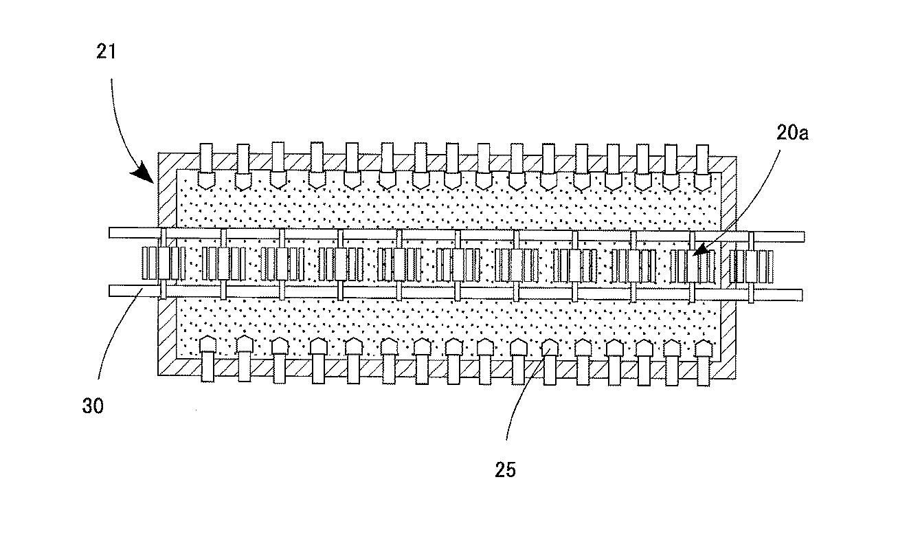
この第1の実施例の粉体塗装装置は、図1に示すように、底面の多孔質材料22を介して流動エアー23が供給される粉体容器21を有する。粉体容器21内には、粉体塗料が収容されている。粉体容器21内の粉体塗料は、下部が底面からの流動エアー23によって液体のような状態で流動する流動層21aになり、上部が霧化状態(クラウド状態)で漂う霧化層21bになる。
As shown in FIG. 1, the powder coating apparatus of the first embodiment has a
粉体容器21内の流動層21aの上面には、摩擦帯電ガン24の多数本に分岐された吐出ノズル25が差し込まれ、この吐出ノズル25から摩擦帯電した粉体塗料が粉体容器21内に供給され、霧化層21bの粉体塗料と混合される。
粉体容器21の材質は、上記の実施例では、ステンレスを採用しているが、導電性樹脂によって形成してもよい。粉体容器21は、接地されており、導電性材料によって形成することにより、粉体容器21の総電荷を少なくすることができる。
The material of the
また、粉体容器21を従来の静電流動浸漬装置と同様に、絶縁材料、例えば、塩化ビニル製のタンクにしても付着量、付き回りに差は生じない。
Further, even if the
粉体容器21の上面には、吸引フード26が設置され、粉体容器21の上面の開口部27から霧化層21bの粉体塗料と混合された摩擦帯電した粉体塗料が引き出されている。
A
吸引フード26によって回収された粉体塗料は、集塵機28を経て塗料タンク29に送られて再利用に供される。
The powder paint collected by the
粉体容器21の上面には、開口部27に沿ってスクリュー搬送装置30が設置され、このスクリュー搬送装置30によって、被塗装物20であるローター20aが回転しながら、開口部27の一端から他端に向かって所定の速度で移送されるようになっている。
On the upper surface of the
粉体容器21の上面の開口部27からは、霧化層21bの粉体塗料と摩擦帯電した粉体塗料とが混合状態で引き出され、この引き出し流路中を被塗装物20であるローター20aが通過し、ローター20aの狭いティース20b間に霧化層21bの粉体塗料と摩擦帯電した粉体塗料とが混合状態で浸入する。
From the
ローター20aのコア軸20cは、スクリュー搬送装置30のチャック31によってマスキングされている。スクリュー搬送装置30のスクリュー32は導電性材料によって形成され、スクリュー32を介して被塗装物20であるローター20aが接地(アース)されている。
The
ローター20aの外面には、霧化層21bの粉体塗料と摩擦帯電した粉体塗料とが付着する。
The powder coating material of the
付着する粉体塗料の膜厚は、ローター20aを移送するスクリュー搬送装置30の速度を変更することにより調整することができる。即ち、ローター20aの移送速度を遅くすれば、粉体塗料の付着時間が長くなるので、それだけ膜厚が厚くなる。反対に移送速度を速くすれば、粉体塗料の付着時間が短くなるので、膜厚が薄くなる。
The film thickness of the adhering powder coating can be adjusted by changing the speed of the
摩擦帯電ガン24の吐出ノズル25は、多数本に分岐され、図3に示すように、ローター20aの移送方向に沿っての対向するように4角形の粉体容器21内に2列に挿し込まれている。
The discharge nozzles 25 of the
吐出ノズル25の向きは、流動層21aの上面に対して、水平、斜め下方、斜め上方に組合せて配置される。
The directions of the
吐出ノズル25の向きを、流動層21aの上面に対して、図4に示すように、水平に、あるいは図5に示すように、斜め上方に向けると、流動層21aの上面から霧状に粉体塗料が立ち昇り難く、反対に、図6に示すように、斜め下方に向けると、流動層21aの上面から霧状に立ち昇り易くなる。したがって、吐出ノズル25の向きを適宜変更することにより、霧化層21bに含まれる粉体塗料の濃度を調整することができる。
When the direction of the
吐出ノズル25は、図7(a)(b)に示すように、向きを自在に変えることができる構造にしてもよい。
As shown in FIGS. 7A and 7B, the
霧化層21bに含まれる粉体塗料の濃度調整は、吐出ノズル25の向きの他、吐出ノズル25から吐出される搬送エアーの量、流動エアー23の量によって行うことができる。
The concentration of the powder coating material contained in the atomized
粉体容器21の側面部には、流動槽21aの高さを一定にするために、オーバーフロー用のスリット33が設置され、オーバーフローした粉体塗料は、塗料タンク29に集められる。この塗料タンク29には、吸引フード26から吸引したオーバースプレー粉が集塵機28を経て回収される。塗料タンク29に集められた粉体塗料は、定量供給装置34を介してインジェクター35によって摩擦帯電ガン24に供給される。
An overflow slit 33 is provided on the side surface of the
また、塗料タンク29には、新粉タンクから粉体塗料が補給される。
The
粉体容器21の上方には、霧化層21bの粉体塗料の濃度を調整するために、ダンパー36を備えた排気ダクト37が設けられ、排気ダクト37は吸引フード26に接続されている。
An
ところで、霧化層21bの粉体塗料が摩擦帯電した粉体塗料と共に、被塗装物20に付着するのは、霧化層21bの粉体塗料と摩擦帯電した粉体塗料とが混合されたことにより、霧化層21bの粉体塗料に疑似帯電が行われたと考えられる。
By the way, the powder coating material of the
このことを実験的に確認するために、図8に示すように、粉体容器21の開口部27の上面に平板のテストピース38を設置し、粉体容器21内の流動層21aの粉体塗料の色を白色にして、摩擦帯電ガン24の吐出ノズル25から粉体容器21内に吐出される粉体塗料の色を緑色にして、摩擦帯電ガン24の吐出ノズル25からの粉体塗料の供給を行った場合、即ち、摩擦帯電ガン24をONにした場合と、摩擦帯電ガン24の吐出ノズル25からの粉体塗料の供給を停止した場合、即ち、摩擦帯電ガン24をOFFにした場合とについて、テストピース38に粉体塗料がどのように付着するのかについて実験を行った。
In order to confirm this experimentally, as shown in FIG. 8, a
実験は、要望膜厚80μmに対して摩擦帯電ガン24からの吐出量を20g/minで、搬送エアーを0.1MPaに設定して行った。
The experiment was performed by setting the discharge amount from the frictional charging
摩擦帯電ガン24がOFFの場合には、テストピース38には粉体容器21内の白色の粉体塗料がほとんど付着しなかった。次いで、摩擦帯電ガン24をONにすると、テストピース38に、白色と緑色の粉体塗料が混合された状態で付着した。この付着した白色と緑色の粉体塗料は、塗膜の内部まで混合された状態で付着しており、白色の粉体塗料は、摩擦帯電により電荷を帯びた緑色の粉体塗料と混合されることにより、疑似帯電して、緑色の粉体塗料と共に、テストピース38に付着したものと考えられる。
この実験結果を纏めると、表1の通りである。
When the frictional charging
The experimental results are summarized in Table 1.
次に、図1に示す実施例の塗装装置を使用し、摩擦帯電ガン24の吐出量30g/min、搬送エアー0.1MPaで、スクリュー搬送装置30の搬送速度を1.0m/minと0.6m/minでモーターロータの塗装実験を行った結果を、表2に示す。
Next, using the coating apparatus of the embodiment shown in FIG. 1, the discharge rate of the
その結果、搬送速度を0.6m/minにした塗装では、搬送速度を1.0m/minの塗装よりも膜厚が厚く、要望膜厚として200μmのものが得られた。 As a result, in the coating with a conveyance speed of 0.6 m / min, the film thickness was thicker than that with a conveyance speed of 1.0 m / min, and a desired film thickness of 200 μm was obtained.
表2は、4ロットの塗装で、各ロット10個ずつの膜厚(μm)の平均値であり、膜厚の測定点は、図9のa〜p点である。 Table 2 shows the average value of film thickness (μm) of 10 lots in 4 lots, and the film thickness measurement points are points a to p in FIG.
上記のようにして塗装したローター20aは、図10に示すように、余剰粉体除去槽39の上で、ローラー刷毛及びエアーナイフで外周の余剰粉を取り除いた後、高周波加熱装置及び熱風循環炉を備える焼付炉40において塗膜を熔融硬化させた後に脱荷される。
As shown in FIG. 10, the
図1の実施例では、摩擦帯電ガン24の吐出ノズル25を流動層21aの上方の霧化層21bに配置したが、図11(a)に示すように、吐出ノズル25を流動層21a内に配置してもよい。吐出ノズル25を流動層21a内に配置した場合、吐出ノズル25から流動層21a内の粉体塗料が逆流するおそれがある。このため、図11(b)又は図11(c)に示すように、吐出ノズル25の供給パイプを、吐出ノズル25の手前で流動層21aの上方に屈曲する部分を設け、逆流を防止することが望ましい。
In the embodiment of FIG. 1, the
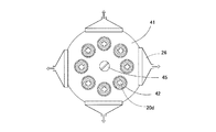
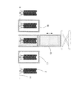
次に、図12及び図13は、自動車部品であるスライドシャフト20dを被塗装物20とする塗装装置の実施例を示している。
Next, FIG.12 and FIG.13 has shown the Example of the coating device which uses the
スライドシャフト20dは、図14に示すように、例えば、長さ230mm、幅23mmで、断面が十文字の形状をしている。
As shown in FIG. 14, the
このスライドシャフト20dの外面は、300μmの塗装を行なった後に、切削により200〜250μmの膜厚に仕上げられる。塗装面は、図14のAの範囲である。粉体塗料は、ナイロン系の粉体塗料、例えば、アルケマ社製のものを使用する。
The outer surface of the
スライドシャフト20dを塗装する際には塗装前に、脱脂を行い、ショットブラストの後、プライマー処理を行い、その後、乾燥を行なう。
When coating the
粉体容器21の上面には、シャフト用設置台41を設け、このシャフト用設置台41に、摩擦帯電ガン24から吐出された帯電した粉体塗料と混合された霧化層21bの粉体塗料を上方へ引き出す粉体流路パイプ42が8本、環状に設置されている。
A
この8本の粉体流路パイプ42内に、被塗装物20である8本のスライドシャフト20dをハンガー43に吊るして、上方から挿入すると、粉体流路パイプ42の内面とスライドシャフト20dの外面との隙間を通過する粉体塗料がスライドシャフト20dの外面に付着する。
粉体流路パイプ42の内径は、スライドシャフト20dの外径より10〜30mm大きい。
When eight
The inner diameter of the
粉体流路パイプ42の内径と被塗装物20であるスライドシャフト20dとの隙間は、粉体塗料の粒度分布、要望膜厚等の条件により、適宜に決定する。
The gap between the inner diameter of the
シャフト用設置台41の中心部には、粉体容器21内の霧化層21bの粉体塗料濃度を調整する濃度調節用ダンパー45を設置している。
A
摩擦帯電ガン24から分岐延長された複数の吐出ノズル25は、粉体容器21の側面に均一に並べられている。
A plurality of
吐出ノズル25は、粉体容器21内の流動層21aの上面よりも上方に差し込まれている。吐出ノズル25を粉体容器21内の流動層21aの上面よりも上方に差し込む理由は、吐出ノズル25から摩擦した粉体塗料が吐出した後、塗装が終了した時点で、吐出をOFFにすると、流動層21aの粉体塗料は水のように漂っているために、吐出ノズル25から摩擦帯電ガン24に向かって流動層21a内の粉体塗料が逆流し、その後、流動層21a内の粉体エアー抜けて、吐出ノズル25と摩擦帯電ガン24との間の供給パイプ内で粉体塗料が閉塞状態になるおそれがある。この閉塞状態をなくすために、吐出ノズル25を流動層21aの上面よりも上方に差し込むことにより、閉塞状態を防止できる。
The
吐出ノズル25を流動層21aに差し込む場合には、図11(b)(c)に示すように、吐出ノズル25の手前の供給パイプに、流動層21aの上面よりも上方に屈曲する屈曲部を形成することにより、吐出ノズル25及び摩擦帯電ガン24への粉体塗料の逆流を防止する。
When the
摩擦帯電ガン24の吐出ノズル25から吐出された電荷を持った粉体塗料は、流動層21a内で流動した粉体塗料に当たり、流動化した粉体塗料と混合され、流動層21a上にクラウド状態(霧化状態)の雰囲気を作る。クラウド状態の粉体塗料は、粉体流路パイプ41とスライドシャフト20dの隙間を通過する。
The charged powder paint discharged from the
この第2の実施例では、スライドシャフト20dを固定したが、より均一性を上げるためにスライドシャフト20dを粉体流路パイプ42内で回転させてもよい。
In the second embodiment, the
粉体流路パイプ41内での塗装は、1回でもよいが、例えば、スライドシャフト20dの上下をひっくり返して再度塗装を行なってもよい。スライドシャフト20dは、塗装後、高周波装置内にてメルト、硬化を行う。
The coating in the
この第2の実施例において、吐出ノズル25からの吐出を100g/minで55秒間行ったところ、膜厚は、表3の通りになった。
In the second example, when the discharge from the
この塗装試験の膜厚の測定箇所は、図15(a)(b)に示す通りである。 The measurement points of the film thickness in this coating test are as shown in FIGS. 15 (a) and 15 (b).
なお、膜厚(μm)は、8本のスライドシャフト20dの平均値を示している。
The film thickness (μm) represents the average value of the eight
第2の実施例では、粉体容器21が円形であり、粉体流路パイプ41の上方の周囲4個所に、吸引フード26を設け、オーバースプレー粉を回収に塗料タンク29に回収している。
In the second embodiment, the
塗料タンク29から摩擦帯電ガン24への供給や、粉体容器21の側面部に流動槽21aの高さを一定にするために、オーバーフロー用のスリット33を設置している点は、第1の実施例と同じである。
The point that the
次に、図16は、冷蔵庫の棚板のスライドレール20eを被塗装物20とするこの発明の第3の実施例を示している。
Next, FIG. 16 shows a third embodiment of the present invention in which the
この実施例では、粉体塗料として、滑り性が良好なポリエステル系のものを使用している。 In this embodiment, as the powder coating material, a polyester-based material having good sliding properties is used.
スライドレール20eは、図17に示すように、L型をしている。
The
粉体容器21は、第1、第2の実施例と同様に、内部に流動層21aと霧化層21bが形成されている。
As in the first and second embodiments, the
粉体容器21は、角型式で、流動層21aの上方の対向面に摩擦帯電ガン24の吐出ノズル25が差し込まれている。
The
霧化層21bの粉体塗料の濃度は、上部に行けばいくほど薄くなりやすい。
The concentration of the powder coating material in the
スライドレール20eは、上下の長さが長いので、膜厚を均一性にするために、被塗装物20であるスライドレール20eを流動層21a内にディッピングした後、スライドレール20eを上昇させて、スライドレール20eが霧化層21b内を十分に通過させることにより安定した均一な塗膜を形成できるようにしている。
Since the
スライドレール20eは、7本をハンガー44に並列に吊るして、粉体容器21の開口部27から粉体容器21に挿入し、塗装後に、上方へ引き上げるようにしている。
Seven
スライドレール20eは、塗装前に、脱脂、リン酸鉄処理、水洗、水切り乾燥を行なう。
The
スライドレール20eは、ハンギングされたまま、粉体容器21の上面にタクト運転にて搬送され、粉体容器21の流動層21aにディッピングされる。
The
そして、ディッピングしたままで摩擦帯電ガン24を作動させ、流動層21aの上面の霧化層21bの粉体塗料と摩擦帯電した粉体塗料とを混合させる。
Then, the frictional charging
その後に、スライドレール20eを上昇させて、摩擦帯電した粉体塗料が混合された霧化層21bを通過させると、スライドレール20eに粉体塗料が均一に付着する。
Thereafter, when the
第3の実施例では、粉体容器21の開口部27の上方に、吸引フード26を設け、オーバースプレー粉を回収に塗料タンク29に回収している。
In the third embodiment, a
塗料タンク29から摩擦帯電ガン24への供給や、粉体容器21の側面部に流動槽21aの高さを一定にするために、オーバーフロー用のスリット33を設置している点は、第1、第2の実施例と同じである。
In order to supply the frictional charging
スライドレール20eは、塗装後、高周波装置内にてメルト、硬化を行う。
The
この第3の実施例において、吐出ノズル25からの吐出量を120g/minにして塗装試験を行ったところ、膜厚は、表4の通りになった。
In the third embodiment, when the coating test was performed with the discharge amount from the
この塗装試験の膜厚の測定箇所は、図17に示す通りである。なお、膜厚(μm)は、1つのハンガー44に吊るした7本のスライドレール20eの平均値を示している。塗装試験は計3回行った。
The film thickness measurement points in this coating test are as shown in FIG. The film thickness (μm) represents the average value of the seven
20 被塗装物
20a ローター
20b ティース
20c コア軸
20d スライドシャフト
20e スライドレール
21 粉体容器
21a 流動層
21b 霧化層
22 多孔質材料
23 流動エアー
24 摩擦帯電ガン
25 吐出ノズル
26 吸引フード
27 開口部
28 集塵機
29 塗料タンク
30 スクリュー搬送装置
31 チャック
32 スクリュー
33 スリット
34 定量供給装置
35 インジェクター
36 ダンパー
37 排気ダクト
38 テストピース
39 余剰粉体除去槽
40 焼付炉
41 シャフト用設置台
42 粉体流路パイプ
43 ハンガー
44 ハンガー
45 濃度調節用ダンパー
20
Claims (8)
Priority Applications (1)
| Application Number | Priority Date | Filing Date | Title |
|---|---|---|---|
| JP2011136932A JP2013000708A (en) | 2011-06-21 | 2011-06-21 | Powder coating device |
Applications Claiming Priority (1)
| Application Number | Priority Date | Filing Date | Title |
|---|---|---|---|
| JP2011136932A JP2013000708A (en) | 2011-06-21 | 2011-06-21 | Powder coating device |
Publications (1)
| Publication Number | Publication Date |
|---|---|
| JP2013000708A true JP2013000708A (en) | 2013-01-07 |
Family
ID=47669852
Family Applications (1)
| Application Number | Title | Priority Date | Filing Date |
|---|---|---|---|
| JP2011136932A Pending JP2013000708A (en) | 2011-06-21 | 2011-06-21 | Powder coating device |
Country Status (1)
| Country | Link |
|---|---|
| JP (1) | JP2013000708A (en) |
Cited By (3)
| Publication number | Priority date | Publication date | Assignee | Title |
|---|---|---|---|---|
| CN103334247A (en) * | 2013-06-13 | 2013-10-02 | 苏州市丹纺纺织研发有限公司 | Electrostatic coating device |
| WO2015141335A1 (en) * | 2014-03-18 | 2015-09-24 | 株式会社東芝 | Nozzle, additive layer manufacturing apparatus, and method for manufacturing additive layer manufacturing product |
| US9401616B2 (en) * | 2013-10-22 | 2016-07-26 | Samsung Sdi Co., Ltd. | Battery pack, energy storage system including battery pack, and method of charging battery pack |
Citations (5)
| Publication number | Priority date | Publication date | Assignee | Title |
|---|---|---|---|---|
| US3807355A (en) * | 1970-04-16 | 1974-04-30 | Westinghouse Electric Corp | Fluidizing bed tank |
| JPH04225856A (en) * | 1990-04-13 | 1992-08-14 | Nordson Corp | Powder feed hopper |
| JPH06285397A (en) * | 1993-04-01 | 1994-10-11 | Asmo Co Ltd | Electrostatic powder coating device |
| JP2003501259A (en) * | 1999-06-15 | 2003-01-14 | アトフィナ | Method for coating an article with a coating and apparatus for performing the method |
| JP2005510351A (en) * | 2001-11-29 | 2005-04-21 | アルケマ | Method for coating an article with a coating and apparatus for carrying out this method |
-
2011
- 2011-06-21 JP JP2011136932A patent/JP2013000708A/en active Pending
Patent Citations (5)
| Publication number | Priority date | Publication date | Assignee | Title |
|---|---|---|---|---|
| US3807355A (en) * | 1970-04-16 | 1974-04-30 | Westinghouse Electric Corp | Fluidizing bed tank |
| JPH04225856A (en) * | 1990-04-13 | 1992-08-14 | Nordson Corp | Powder feed hopper |
| JPH06285397A (en) * | 1993-04-01 | 1994-10-11 | Asmo Co Ltd | Electrostatic powder coating device |
| JP2003501259A (en) * | 1999-06-15 | 2003-01-14 | アトフィナ | Method for coating an article with a coating and apparatus for performing the method |
| JP2005510351A (en) * | 2001-11-29 | 2005-04-21 | アルケマ | Method for coating an article with a coating and apparatus for carrying out this method |
Cited By (4)
| Publication number | Priority date | Publication date | Assignee | Title |
|---|---|---|---|---|
| CN103334247A (en) * | 2013-06-13 | 2013-10-02 | 苏州市丹纺纺织研发有限公司 | Electrostatic coating device |
| US9401616B2 (en) * | 2013-10-22 | 2016-07-26 | Samsung Sdi Co., Ltd. | Battery pack, energy storage system including battery pack, and method of charging battery pack |
| WO2015141335A1 (en) * | 2014-03-18 | 2015-09-24 | 株式会社東芝 | Nozzle, additive layer manufacturing apparatus, and method for manufacturing additive layer manufacturing product |
| JP2015178192A (en) * | 2014-03-18 | 2015-10-08 | 株式会社東芝 | Nozzle, lamination molding device, and production method of lamination molding object |
Similar Documents
| Publication | Publication Date | Title |
|---|---|---|
| US6528125B1 (en) | Corrosion resistant powder coated metal tube and process for making the same | |
| CN1261229C (en) | Electrostatic spray coating apparatus and method | |
| US5711489A (en) | Electrostatic powder coating method and apparatus | |
| JP5721407B2 (en) | Powder coating equipment | |
| JP2002508247A (en) | Powder coating method | |
| CN100366348C (en) | Powder coating process with electrostatically charged fluidized bed | |
| KR20180022479A (en) | Powder coating system using zinc primer and powder coating method thereof | |
| JP2013000708A (en) | Powder coating device | |
| JP2003501259A (en) | Method for coating an article with a coating and apparatus for performing the method | |
| TWI220868B (en) | Multicolored pattern coating facilities and multicolored pattern coating method | |
| Barletta et al. | Electrostatic fluidized bed deposition of a high performance polymeric powder on metallic substrates | |
| JP2013165604A (en) | Powder coating method for motor core | |
| JP5467949B2 (en) | Powder coating method | |
| JP2015073941A (en) | Powder coating method | |
| US7217444B2 (en) | Process for electrostatic powder coating an article using triboelectrically charged powder with air jet assist | |
| JP4935086B2 (en) | Coating method using rotary atomizing coating equipment | |
| JP7230765B2 (en) | Painting booth and painting method | |
| JP2013144277A (en) | Powder painting method | |
| CN108698066A (en) | The method and system of the inner wall of cavity is covered using the protective layer made of antiseptic wax or preservative | |
| CN203976953U (en) | A kind of finishing system | |
| JP2010269262A (en) | Coating booth for electrostatic powder coating | |
| JP2002177826A (en) | Electrostatic powder coater | |
| JP2009113019A (en) | Rotary spray coating method and apparatus for liquid | |
| JP2007237099A (en) | Method of coating structure having recess | |
| JP4517646B2 (en) | How to paint a car body |
Legal Events
| Date | Code | Title | Description |
|---|---|---|---|
| A621 | Written request for application examination |
Free format text: JAPANESE INTERMEDIATE CODE: A621 Effective date: 20140326 |
|
| A131 | Notification of reasons for refusal |
Free format text: JAPANESE INTERMEDIATE CODE: A131 Effective date: 20141224 |
|
| A977 | Report on retrieval |
Free format text: JAPANESE INTERMEDIATE CODE: A971007 Effective date: 20141225 |
|
| A02 | Decision of refusal |
Free format text: JAPANESE INTERMEDIATE CODE: A02 Effective date: 20150421 |