WO2015137222A1 - 電源システム - Google Patents
電源システム Download PDFInfo
- Publication number
- WO2015137222A1 WO2015137222A1 PCT/JP2015/056460 JP2015056460W WO2015137222A1 WO 2015137222 A1 WO2015137222 A1 WO 2015137222A1 JP 2015056460 W JP2015056460 W JP 2015056460W WO 2015137222 A1 WO2015137222 A1 WO 2015137222A1
- Authority
- WO
- WIPO (PCT)
- Prior art keywords
- power storage
- storage device
- power
- voltage
- capacity
- Prior art date
Links
Images


Classifications
-
- H—ELECTRICITY
- H02—GENERATION; CONVERSION OR DISTRIBUTION OF ELECTRIC POWER
- H02J—CIRCUIT ARRANGEMENTS OR SYSTEMS FOR SUPPLYING OR DISTRIBUTING ELECTRIC POWER; SYSTEMS FOR STORING ELECTRIC ENERGY
- H02J7/00—Circuit arrangements for charging or depolarising batteries or for supplying loads from batteries
- H02J7/0013—Circuit arrangements for charging or depolarising batteries or for supplying loads from batteries acting upon several batteries simultaneously or sequentially
- H02J7/0024—Parallel/serial switching of connection of batteries to charge or load circuit
-
- H—ELECTRICITY
- H01—ELECTRIC ELEMENTS
- H01M—PROCESSES OR MEANS, e.g. BATTERIES, FOR THE DIRECT CONVERSION OF CHEMICAL ENERGY INTO ELECTRICAL ENERGY
- H01M10/00—Secondary cells; Manufacture thereof
- H01M10/42—Methods or arrangements for servicing or maintenance of secondary cells or secondary half-cells
- H01M10/425—Structural combination with electronic components, e.g. electronic circuits integrated to the outside of the casing
-
- H—ELECTRICITY
- H01—ELECTRIC ELEMENTS
- H01M—PROCESSES OR MEANS, e.g. BATTERIES, FOR THE DIRECT CONVERSION OF CHEMICAL ENERGY INTO ELECTRICAL ENERGY
- H01M10/00—Secondary cells; Manufacture thereof
- H01M10/42—Methods or arrangements for servicing or maintenance of secondary cells or secondary half-cells
- H01M10/44—Methods for charging or discharging
- H01M10/441—Methods for charging or discharging for several batteries or cells simultaneously or sequentially
-
- H—ELECTRICITY
- H02—GENERATION; CONVERSION OR DISTRIBUTION OF ELECTRIC POWER
- H02P—CONTROL OR REGULATION OF ELECTRIC MOTORS, ELECTRIC GENERATORS OR DYNAMO-ELECTRIC CONVERTERS; CONTROLLING TRANSFORMERS, REACTORS OR CHOKE COILS
- H02P27/00—Arrangements or methods for the control of AC motors characterised by the kind of supply voltage
- H02P27/04—Arrangements or methods for the control of AC motors characterised by the kind of supply voltage using variable-frequency supply voltage, e.g. inverter or converter supply voltage
- H02P27/06—Arrangements or methods for the control of AC motors characterised by the kind of supply voltage using variable-frequency supply voltage, e.g. inverter or converter supply voltage using dc to ac converters or inverters
- H02P27/08—Arrangements or methods for the control of AC motors characterised by the kind of supply voltage using variable-frequency supply voltage, e.g. inverter or converter supply voltage using dc to ac converters or inverters with pulse width modulation
-
- H—ELECTRICITY
- H01—ELECTRIC ELEMENTS
- H01M—PROCESSES OR MEANS, e.g. BATTERIES, FOR THE DIRECT CONVERSION OF CHEMICAL ENERGY INTO ELECTRICAL ENERGY
- H01M2220/00—Batteries for particular applications
- H01M2220/20—Batteries in motive systems, e.g. vehicle, ship, plane
-
- Y—GENERAL TAGGING OF NEW TECHNOLOGICAL DEVELOPMENTS; GENERAL TAGGING OF CROSS-SECTIONAL TECHNOLOGIES SPANNING OVER SEVERAL SECTIONS OF THE IPC; TECHNICAL SUBJECTS COVERED BY FORMER USPC CROSS-REFERENCE ART COLLECTIONS [XRACs] AND DIGESTS
- Y02—TECHNOLOGIES OR APPLICATIONS FOR MITIGATION OR ADAPTATION AGAINST CLIMATE CHANGE
- Y02E—REDUCTION OF GREENHOUSE GAS [GHG] EMISSIONS, RELATED TO ENERGY GENERATION, TRANSMISSION OR DISTRIBUTION
- Y02E60/00—Enabling technologies; Technologies with a potential or indirect contribution to GHG emissions mitigation
- Y02E60/10—Energy storage using batteries
Definitions
- the present invention relates to a power supply system, and more particularly to an energy regenerative power storage system including a power storage device such as a lithium ion secondary battery, a bidirectional DC-DC converter, and the like.
- a power storage device such as a lithium ion secondary battery, a bidirectional DC-DC converter, and the like.
- Lithium ion secondary batteries have been mainly used for mobile applications as lightweight, high energy density storage devices. In recent years, higher output of lithium ion secondary batteries has progressed, and it has come to be used for large mobile applications such as hybrid vehicles and hybrid railway vehicles. As a development trend of lithium ion secondary batteries, development of high capacity and high energy density as shown in FIG. 5 and development of bipolar with low capacity and high output density are progressing. As an application of the electricity storage device, the peak output is high but is often instantaneous. Of the above-mentioned storage devices with advanced bipolarization, when a storage device with a large capacity and a high energy density is used alone, more energy than necessary is mounted.
- the power storage device when configured with only a small capacity and a high power density, it has a configuration that has more output than necessary. Thus, when either one of the power storage devices is employed, the configuration has unnecessary energy and output, leading to an increase in weight, volume, and cost of the power storage system. For this reason, an example has been proposed in which a high output type and a high capacity type storage device are connected via a bidirectional DC-DC converter.
- a DC-DC converter is disposed only for the auxiliary secondary battery block. Then, the auxiliary secondary battery block and the main secondary battery block are operated in parallel by boosting the output voltage of the auxiliary secondary battery block to the same level as that of the main secondary battery block by the DC-DC converter. It describes that charging / discharging is performed.
- the main secondary battery block is always connected without passing through the DC-DC converter, and the auxiliary secondary battery block is always connected through the DC-DC converter.
- Patent Document 2 for use in electric vehicles such as hybrid vehicles and electric vehicles, the first power storage device and the second power storage device 2 connected in parallel via a bidirectional DC-DC converter are boosted and used to open and close the relay.
- the configuration of the power supply system controlled by is introduced.
- relays are arranged so that two high-voltage batteries can be connected individually or in parallel.
- the first power storage device is always connected without passing through the DC-DC converter, and the second power storage device 2 is always connected through the DC-DC converter. If the power storage device that passes through the DC-DC converter and the power storage device that does not pass through the DC-DC converter are determined in this way, the efficiency may deteriorate depending on the load pattern, and the application range will be narrowed.
- the switch when the switch is configured so that a plurality of power supply paths can be obtained, various power paths are conceivable, so it is necessary to design for safety.
- the secondary battery is a rechargeable battery, when it is overcharged, the lead acid battery, nickel metal hydride battery, or nickel cadmium battery undergoes electrolysis of water, increasing the internal pressure and generating heat.
- an organic solvent is used as an electrolyte solution, and thus an electrolyte solution decomposition reaction may occur.
- a high output power storage device can be connected in parallel by turning on / off the switch. In this case, it is more efficient to transfer the energy without using the DC-DC converter when the power storage device to be connected is cut off and the high output type power storage device is main. On the other hand, when the switch is turned ON / OFF, the power path becomes complicated, and it is necessary to cope with the problem.
- the conventional power supply system is configured as described above, a secondary battery that connects a plurality of power storage devices via a DC-DC converter and configures an appropriate power path by turning on / off the switch is provided.
- the used multiple power supply system it is difficult to efficiently transfer power and to keep the power storage device in a state in which it is difficult to be overcharged or discharged.
- the present invention has been made to solve such a problem, and an object of the present invention is to connect a plurality of power storage devices via a bidirectional DC-DC converter, and to turn on / off the switch.
- a multiple power supply system that configures an appropriate power path by turning OFF, power is efficiently exchanged, and even if the first power storage device and the second power storage device are electrically connected, the overcharge state does not occur.
- the power storage device can be kept in a stable state. That is, an object of the present invention is to provide a power supply system that can efficiently transfer power and can keep the power storage device from being overcharged or overdischarged.
- the power supply system includes a bidirectional DC-DC that transfers power between the first and second power storage devices connected in parallel to the power transfer facility and the first and second power storage devices.
- a converter a switch that can independently disconnect the first and second power storage devices from the load device, and a control device that controls the switch and the DC-DC converter).
- the nominal voltage of the first power storage device is Va
- the rated capacity of the first power storage device is U1
- the nominal voltage of the second power storage device is Vb
- the rated capacity of the second power storage device is U2.
- the first and second power storage devices are configured to satisfy the relational expressions Va ⁇ Vb, U1> U2, and the second power storage device to the first power storage device.
- the nominal value of the first power storage device is set so that the voltage of the first power storage device that rises when the electric energy moves to the predetermined upper limit value V1Hlim or the capacity of the first power storage device does not exceed the predetermined upper limit value U1lim.
- the voltage Va, the rated capacity U1 of the first power storage device, the nominal voltage Vb of the second power storage device, and the rated capacity U2 of the second power storage device are set.
- the power supply system according to the present invention is configured as described above, it is possible to obtain a power supply system in which the power storage device can be kept from being overcharged or overdischarged.
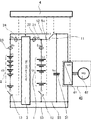
- FIG. 1 is a schematic diagram of a power supply system according to Embodiment 1 of the present invention.
- FIG. 5 is a schematic diagram showing voltage-capacitance characteristics of the power storage device according to Embodiment 1 of the present invention.
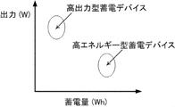
- FIG. 3 is a schematic diagram showing voltage-power amount characteristics of the power storage device according to Embodiment 1 of the present invention. It is a flowchart which shows operation
- Embodiment 1 the configuration of the power supply system of the present invention will be described with reference to the drawings.
- the drawings are schematic and conceptually illustrate functions and structures. Also, the drawings do not reflect the exact size of the components shown. Unless otherwise specified, the basic configuration of the power supply system is common to all the embodiments. Moreover, what attached
- FIG. 1 is a schematic diagram schematically showing a configuration of a power supply system according to the present embodiment.
- a power supply system according to this embodiment will be described below with reference to FIG.
- the power transmission / reception facility of the present invention also includes a combination of power transmission / reception by a facility having an electric device that consumes power and a photovoltaic power generation facility.
- the power supply system of this embodiment includes a motor generator 42, an inverter 41, a first power storage device 1, a second power storage device 2, a bidirectional DC-DC converter 3, a smoothing capacitor 31, a switch (11, 12). 13) and a control device 4.
- the inverter 41 converts AC power generated by the motor generator 42 into DC power, or supplies AC power necessary for the motor generator from the power supply system. Since the motor generator 42 is a device that becomes a load that consumes power or becomes a generator, it corresponds to a power transfer facility.
- the bidirectional DC-DC converter 3 is a bidirectional DC-DC converter capable of stepping up and down the voltage, and includes a first power storage device on the low voltage side and a second power storage device on the high voltage side.
- the bidirectional DC-DC converter 3 may be called a reversible converter, a reversible converter, a reversible converter, a reversible chopper, or the like, but has the same meaning.
- the first power storage device 1 is a high-capacity power storage device.
- the second power storage device 2 is a high output power storage device.
- the first and second power storage devices can be expressed by the relation Va. It is set so as to satisfy ⁇ Vb, U1> U2. Since Va ⁇ Vb, when power is supplied from the first power storage device 1 to the second power storage device 2 via the bidirectional DC-DC converter 3, a boosting operation is performed. Conversely, the power supply from the second power storage device to the first power storage device 2 is a step-down operation.
- the high-capacity power storage device uses two types of power storage devices having different discharge capacities (unit: Ah), and the power storage device having a larger discharge capacity is called a high-capacity power storage device.
- the discharge capacity of one cell which is the smallest battery unit, is small, but when two or more cells are connected in parallel to increase the discharge capacity, the discharge capacity after parallel connection is compared.
- the power storage device having a higher discharge capacity is referred to as a high capacity power storage device.
- a high-output power storage device uses two types of power storage devices that have different power (unit: W) that can be input / output to / from the power storage device. Called a device.
- W power that can be input / output
- the parallel connection A power storage device having a higher power compared to the later power is referred to as a high-power power storage device.
- a high-power power storage device since two types of power storage devices are used in comparison, a case of high capacity and high output can be considered in this case.
- the voltage of the power storage device is variable, and what is displayed in the catalog or the like is often a nominal voltage.
- the nominal voltage is a voltage value announced by the power storage device manufacturer, and may indicate a rated voltage value or an average voltage when the amount of power at full charge is divided by the rated capacity. For this reason, the nominal voltage is a voltage value including the rated voltage and the average voltage.
- the capacity of the power storage device is variable, what is displayed in the catalog or the like has a large rated capacity.
- the rated capacity may indicate the discharge capacity when discharging at the current value specified by the manufacturer from the time of full charge, or the storage capacity at the time of full charge. Since there is a case where it is synonymous with the nominal capacity which is the capacity value announced by the manufacturer, the rated capacity includes the nominal capacity and the storage capacity when fully charged.
- Va Nominal voltage or rated voltage or average voltage of the first power storage device U1: Nominal capacity or rated capacity of the first power storage device or power storage capacity at full charge
- V1 Voltage of the first power storage device
- V1max First Voltage or upper limit voltage when the rated capacity of the power storage device is charged
- V1min Voltage or lower limit voltage when the rated capacity of the first power storage device is discharged
- V1Hlim Maximum voltage that can safely charge the first power storage device (safety maximum) Voltage)
- U1lim Capacity capable of safely storing power in the first power storage device (maximum safe capacity)
- Wh1 Nominal power amount or rated power amount of the first power storage device
- Vb Nominal voltage or rated voltage or average voltage of the second power storage device
- U2 Nominal capacity or rated capacity of the second power storage device or power storage at full charge Capacity
- V2 Voltage of the second power storage device
- V2max Voltage or upper
- a bidirectional DC-DC converter 3 is disposed between the first power storage device 1 and the second power storage device 2.
- the bidirectional DC-DC converter 3 is a bidirectional DC-DC converter that can step up and down the voltage and can transfer power between the first power storage device 1 and the second power storage device 2. .
- the bidirectional DC-DC converter 3 exchanges power between the first power storage device 1 and the inverter or between the second power storage device 2 and the inverter 41 depending on the connection method of the switch.
- the motor generator 42 may be, for example, a three-phase winding induction motor or a permanent magnet type three-phase synchronous motor, but is not limited thereto.
- the motor generator 42 is used as a motor for generating a driving force for a generator during a regenerative operation and for a power running operation.
- the motor generator 42 is cited as a load device and a power generation device, but this is only an example, and the power generation device may be a solar cell panel and the load may be a household load facility.
- the power generated during regeneration is converted from AC to DC power by the inverter 41 and supplied to the multiple power supply system.
- the multiple power supply system specifically includes a first power storage device 1 and a second power storage device 2 having different capacities and voltages, a switch connecting them, and voltage adjustment as shown in FIG.
- the power supply system includes a bidirectional DC-DC converter 3 and the like.
- the power transmission / reception equipment 40 is configured to perform power consumption or power generation during regeneration, such as the motor generator 42.
- the inverter 41 is a general three-phase inverter, and an inverter of variable voltage variable frequency (VVVF) control or pulse width modulation (PWM) control is used to perform bidirectional DC-AC conversion.
- VVVF variable voltage variable frequency
- PWM pulse width modulation
- the smoothing capacitor 31 is arranged in parallel to the inverter 41 and arranged to smooth the ripple current generated in the inverter 41.
- the bidirectional DC-DC converter 3 includes a power semiconductor switching element, a diode, a capacitor, a reactor, and the like.
- a switching element capable of ON / OFF control such as an IGBT (Insulated Gate Bipolar Transistor), a power MOS-FET, a power bipolar transistor, or the like is used.
- the bidirectional DC-DC converter 3 may be a non-insulated bidirectional DC-DC converter 3 using the above-described elements, an insulated bidirectional DC-DC converter 3 using a transformer, or the like.
- a high-capacity secondary battery is used for the first power storage device 1.
- lithium ion secondary batteries are used in mobile applications because high weight energy density and high volume energy density are emphasized.
- the first power storage device 1 may be a high-capacity power storage device.
- the first power storage device 1 is responsible for most of the energy output of the system. For this reason, the charge state (SOC: State of Charge) of the first power storage device 1 is charged to a high SOC close to 100%. Since the lithium ion secondary battery as the first power storage device 1 reaches the upper limit voltage due to voltage fluctuation at the time of high rate charging such as regeneration when the SOC is close to 100%, the high rate charging at SOC 95% or more is the second It is better to use the power storage device 2.
- SOC State of Charge
- the second power storage device 2 a high-output power storage device such as a lithium ion secondary battery, a nickel metal hydride battery, or an electric double layer capacitor is used. That is, the second power storage device 2 is a power storage device having a small capacity and a high output density as compared with the first power storage device 1.
- the main application of the second power storage device 2 that is an element constituting the multiple power supply system is the storage of regenerative power generated by the motor generator 42 as power transfer equipment and the supply of instantaneous power. Since the first power storage device 1 places importance on high energy density, it is not suitable for high-input / output instantaneous power, and in order to support high-input / output power, the amount of power storage device mounted is increased to increase power consumption.
- the main purpose of the second power storage device 2 is to reduce the high input / output power burden of the first power storage device 1 and to carry out power regeneration and high output power.
- the SOC of the second power storage device 2 avoids 100% and is used around SOC 50% to 70%. Specifically, it is preferable to set the use area to about SOC 20% to SOC 90%.
- the nominal voltage Va is 2.0 to 4.2 V ⁇ the number of cells.
- the nominal voltage Va differs depending on the active material used. For example, in the case where lithium cobaltate, lithium nickelate, lithium manganate and a mixed active material thereof are used for the positive electrode and a carbon material is used for the negative electrode, 3.6 V to 3.8 V in a single cell, When lithium titanate is used, it is 2.2V to 2.5V in a single cell. When lithium iron phosphate is used for the positive electrode and a carbon material is used for the negative electrode, the voltage is 3.2 V to 3.3 V in a single cell.
- Vb the nominal voltage is similarly denoted as Vb.
- Vb may be indicated not by a nominal voltage but by a normal upper limit voltage.
- Vb is often expressed as 1.2V ⁇ cell number in a nickel metal hydride battery.
- lead-acid batteries 2.0V ⁇ number of cells is often indicated.
- Vb is 2.0 to 4.2 V ⁇ the number of cells as in the first power storage device 1.
- the voltage of the first power storage device 1 is set to V1, and the voltage V2 of the second power storage device 2 is set.
- the voltage V1 of the first power storage device 1 and the voltage V2 of the second power storage device 2 are variable, but V1 ⁇ V2 It is comprised so that.
- battery voltages that are variable such as V1 and V2 are not displayed, but are represented by nominal voltages. It is represented by a nominal voltage Va of the first power storage device 1 that is a representative value of V1 and a nominal voltage Vb of the second power storage device 2 that is a representative value of V2.
- the configuration is such that Va ⁇ Vb.
- the storage capacity of the first power storage device 1 is expressed as U1
- the storage capacity of the second power storage device 2 is expressed as U2, U1> U2 To be configured.
- the storage capacity U1 of the first power storage device 1 indicates the nominal capacity, rated capacity, and discharge capacity from a fully charged state of the battery.
- the capacity is indicated by 1 hour rate capacity. is there.
- the 1-hour rate capacity is the discharge capacity when the battery is discharged at the current value when the nominal capacity or rated capacity of the battery is discharged in 1 hour.
- the discharge capacity when a battery having a rated capacity of 5 Ah is discharged at 5 A.
- the storage capacity U2 of the second power storage device 2 indicates the nominal capacity, rated capacity, and discharge capacity from a fully charged state of the battery.
- the 5-hour rate capacity indicates a capacity capable of flowing a battery having a rated capacity U1Ah (ampere hour) at a current value of U1 / 5 for 5 hours.
- the discharge capacity when a battery having a rated capacity of 5 Ah is discharged at 1 A is a 5-hour rate capacity.
- the storage capacity display of the power storage device is not limited to this because it differs depending on the manufacturer.
- the amount of power of the first power storage device 1 is Wh1
- the amount of power of the second power storage device 2 is Wh2
- Wh1> Wh2 Set as follows.
- V1max is a voltage of SOC 100% in first power storage device 1.
- the first power storage device 1 and the high second power storage device 2 are electrically connected due to a system abnormality, the first power storage device 1 having a lower voltage than the second power storage device 2 having a higher voltage. Current flows and the voltages try to be equal. At this time, the current capacity flowing from the second power storage device 2 into the first power storage device 1 is ⁇ U, and the voltage increase of the first power storage device 1 at this time is ⁇ V1.
- the capacity of ⁇ U1 must be accepted by the first power storage device 1 and set to a value that will not be unsafe even if the voltage V1 increases by ⁇ V1. . That means V1Hlim ⁇ V1max + ⁇ V1 It is necessary to. Moreover, if the capacity (safety maximum capacity) that can be safely stored in the first power storage device 1 is U1lim, U1lim ⁇ U1 + ⁇ U1 It is necessary to.
- the first and second power storage devices are configured so that Va ⁇ Vb, U1> U2 and designed so as not to exceed the safe maximum voltage V1Hlim, switching of the DC-DC converter or switching of the switch Even if a malfunction occurs, a multiple power supply system that can be safely charged and discharged can be obtained.
- the power supply system of the present embodiment includes first (1) and second (2) power storage devices connected in parallel to the power transfer facility (40), and first (1) and second (2) power storage devices.
- a bidirectional DC-DC converter (3) for transferring power between devices, a switch for independently disconnecting the first and second power storage devices from the load device, a switch and a DC-DC converter
- a control device (4) for controlling. Further, when the nominal voltage of the first power storage device is Va, the rated capacity of the first power storage device is U1, the nominal voltage of the second power storage device is Vb, and the rated capacity of the second power storage device is U2.
- the first and second power storage devices are configured to satisfy the relational expressions Va ⁇ Vb, U1> U2, and the second power storage device to the first power storage device.
- the nominal value of the first power storage device is set so that the voltage of the first power storage device that rises when the electric energy moves to the predetermined upper limit value V1Hlim or the capacity of the first power storage device does not exceed the predetermined upper limit value U1lim.
- the voltage Va, the rated capacity U1 of the first power storage device, the nominal voltage Vb of the second power storage device, and the rated capacity U2 of the second power storage device are set.
- the nominal voltages (Va, Vb) and the rated capacities (U1, U2) of the first and second power storage devices are created at the time of manufacture as the design specifications of the respective storage batteries.
- the upper limit values (V1Hlim, U1lim) are storage battery reference values determined based on the storage battery design specifications.
- separate the 1st and 2nd electrical storage apparatus of this form from a load apparatus each independently is arrange
- the power supply system of the present embodiment includes a first power path (51) connected from the first power storage device (1) to the power transfer facility (40), and a first power path (51) connected from the second power storage device to the power transfer facility.
- the power storage device is overcharged even when a fault occurs in the switch and the power storage devices are short-circuited. And can be kept in a state where it is difficult to overdischarge.
- the safe maximum voltage V1Hlim of the first power storage device 1 varies depending on the active material used.
- V1Hlim is 4.3 V per unit cell. The following is preferable. This is because, if V1Hlim is 4.3 V or less per unit cell, it can be used reversibly in the short term without causing side reactions such as decomposition of the electrolyte.
- V1Hlim When V1Hlim is larger than 4.3V per unit cell, the internal pressure of the battery may increase due to side reactions such as decomposition of the electrolyte, and when it is 4.5V or more, a battery heat generation phenomenon may occur.
- V1Hlim When lithium titanate is used for the negative electrode, V1Hlim is set to 3.5 V or less in a single cell. If the voltage is higher than 3.5 V in a single cell, the internal pressure of the battery may increase due to side reactions such as decomposition of the electrolyte, and if it is 4.5 V or more in a single cell, a battery heat generation phenomenon may occur.
- V1Hlim When lithium iron phosphate is used for the positive electrode and a carbon material is used for the negative electrode, V1Hlim needs to be 4.0 V or less in a single cell. If the voltage is higher than 4.0 V in a single cell, the internal pressure of the battery may increase due to side reactions such as decomposition of the electrolyte, and if it is 4.5 V or higher in a single cell, a battery heat generation phenomenon may occur.
- the safe maximum capacity U1lim of the first power storage device 1 varies depending on the battery, but generally U1lim is preferably 1.2 times or less of U1. . This is because if U1lim is 1.2 times or less of U1, it will be in a range that can be used reversibly without causing side reactions such as decomposition of the electrolyte in the short term. Lithium ion secondary batteries are often closed systems to prevent the ingress of outside air. If U1lim is larger than 1.2 times U1, the internal pressure of the battery may increase due to side reactions such as decomposition of the electrolyte. Because. Further, if U1lim is twice or more of U1, a battery heat generation phenomenon may occur.
- the amount of power that moves when the first power storage device 1 and the second power storage device 2 having a high voltage are electrically connected due to a system abnormality is equal to or less than the power amount Wh2 of the second power storage device 2. Because there is Wh2 ⁇ ⁇ Wh It becomes.
- the first power storage device 1 needs to be designed not to reach the power amount Wh1lim that can be stored safely even when the power amount Wh2 of the second power storage device 2 is received. That means Wh1lim ⁇ 1.2 ⁇ Wh1 ⁇ Wh1 + Wh2 It is necessary to set the relationship as follows. The above equation is organized as follows. Wh2 ⁇ 0.2 ⁇ Wh1 That is, if Wh2 is set to 0.2 times or less of Wh1, the region can be safely charged.
- the above-described invention is summarized as follows.
- the amount of power that is the product of the nominal voltage and the rated capacity of the first power storage device is Wh1
- the amount of power that is the product of the nominal voltage and the rated capacity of the second power storage device is Wh2. If the first and second power storage devices are designed so that Wh2 is 0.2 times Wh1 or less, even if the power storage system malfunctions and the power storage devices are short-circuited, The device can be kept in a state where it is difficult to overcharge and overdischarge. This is particularly effective when lithium iron phosphate is used for the positive electrode.
- V12max V12max + (V2max-V1max) x Wh2 ⁇ (Wh1 + Wh2)
- V12max V12max ⁇ V1max + (V2max-V1max) x Wh2 ⁇ (Wh1 + Wh2)
- this value is set so that V1Hlim> V12max.
- V1 of first power storage device 1 the relationship between voltage V1 of first power storage device 1 and voltage V2 of second power storage device 2 is expressed as V1 ⁇ V2. Therefore, when the first power storage device 1 and the second power storage device 2 are connected when the system is abnormal, V1 increases and V2 decreases. Accordingly, V1 must define the safe maximum voltage V1Hlim, and V2 must define the safe minimum voltage V2Llim.
- the safe minimum voltage V2Llim of the 2nd electrical storage apparatus 2 changes with active materials used.
- the capacity of U1 is discharged from the fully charged state.
- the applied voltage is 2.5V to 3.0V per unit cell.
- the safe minimum voltage V2Llim of the second power storage device 2 is set to 0.5 V to 1.5 V per unit cell. More preferably, the safe minimum voltage V2Llim is set to 1.0V.
- the voltage at which the capacity of U1 is discharged from the fully charged state is about 1.5 V, so it is necessary to set V2Llim to about 1.0 V in a single cell.
- the voltage at which the capacity of U1 is discharged from the fully charged state is about 2 V. Therefore, the safe minimum voltage V2Llim of the second power storage device 2 is , Set 0.5V to 1.5V per single cell.
- the safe minimum voltage V2Llim is set to 1.0V.
- V2Llim 1.0V ⁇ the number of series cells may be set.
- V1min is a voltage of SOC 0% in the first power storage device 1.
- V2min is a voltage of SOC 0% in the second power storage device 2.
- V2Llim ⁇ V12min Set As this value, V2Llim ⁇ V12min Set to be.
- FIG. 2 shows the voltage-capacitance characteristics of the first power storage device 1 and the voltage-capacitance characteristics of the second power storage device 2.
- FIG. 3 shows the voltage-power amount characteristics of the first power storage device 1 and the voltage-power amount characteristics of the second power storage device 2.
- the control device 4 of this embodiment performs on / off of the switches 11, 12, 13, current measurement, voltage measurement, control of the DC-DC converter 3, and control of the inverter 41.
- the voltage is measured by measuring the voltage V1 of the first power storage device 1, the voltage V2 of the second power storage device 2, and the voltage Vc of the smoothing capacitor (snubber capacitor) 31.
- the smoothing capacitor a capacitor having good frequency characteristics is used, and a film capacitor, an oil capacitor, an aluminum electrolytic capacitor, or the like is used.
- the current measurement includes the current I1a entering / exiting the first power storage device 1, the current I1b between the first power storage device 1 and the DC-DC converter 3, the current I2a entering / exiting the second power storage device 2, and the second power storage device. 2 and the current I2b between the DC-DC converter 3 are measured.
- the third switch 11 is a switch that switches between the power line (first power path 51) of the first power storage device 1 and the power line (second power path 52) of the second power storage device 2.
- the first switch 12 opens and closes the negative power line 53 of the first power storage device 1
- the second switch 13 opens and closes the negative power line 53 of the second power storage device 2.
- the switch 2 and the switch 3 are normally open.
- connection state of the multiple power supply system when power running (supplying power from the power storage device to the motor generator 42) is the main state, power is supplied from the first power storage device 1 that is a large-capacity power storage device. At this time, if power is supplied from the first power storage device 1 via the DC-DC converter 3, the efficiency ⁇ of the DC-DC converter 3 is applied, so that the first power storage device 1 passes through the DC-DC converter 3. Do not connect. In this case, the switch 11 is connected to the power line (first power path 51) of the first power storage device 1, and the switch 12 and the switch 13 are in a connected state.
- the second power storage device 2 that is a high-power power storage device is connected to the inverter 41 without passing through the DC-DC converter 3.
- the switch 1 is connected to the power line (second power path 52) of the second power storage device 2, and the switch 12 and the switch 13 are in a connected state. This state is referred to as a connected state 2.
- connection of a plurality of power storage devices having different voltages is switched by a switch.
- the voltage of the smoothing capacitor 31 connected in parallel is connected. Since the voltage of the smoothing capacitor 31 is the voltage of the connected power storage device, when switching to a power storage device having a different voltage, it is necessary to switch the connection after aligning the voltages.
- Fig. 4 shows an example of how to operate the switch when shifting from connection state 1 to connection state 2.
- the smoothing capacitor voltage Vc V1.
- the switch 11 is connected to the power line of the second power storage device 2.
- the voltage Vc of the smoothing capacitor is boosted to V2 via the DC-DC converter 3 in the first power storage device 1, and the switch 13 is closed.
- Example 1 of this embodiment will be described.
- a lithium ion secondary battery using a mixed active material of cobalt, nickel, and manganese for the positive electrode and a graphite active material for the negative electrode was used in the first power storage device 1 in 80 cells in series.
- the nominal voltage Va of the first power storage device 1 was 296 V
- the rated capacity U1 was 45 Ah
- the power capacity Wh1 was 13.32 kWh
- the voltage V1max when the first power storage device 1 was charged by 45 Ah was 328 V.
- the safe maximum voltage V1Hlim of the first power storage device 1 is 344V
- the capacity U1lim that can be safely stored in the first power storage device 1 is 54Ah.
- a lithium ion secondary battery using a mixed active material of cobalt, nickel, and manganese for the positive electrode and using hard carbon as the active material for the negative electrode was used in the second power storage device 2 in a series of 100 cells.
- the nominal voltage Vb of the second power storage device 2 was 370 V
- the rated capacity U2 was 4 Ah
- the power capacity Wh2 was 1.48 kWh
- the voltage V2max when the second power storage device 2 was charged 4 Ah was 410 V.
- the maximum safe voltage V2Hlim of the second power storage device 2 was set to 430V.
- the minimum safe voltage V2Llim of the second power storage device 2 is set to 100V. In this case, Va ⁇ Vb, U1> U2, and 0.2 ⁇ Wh1> Wh2.
- the voltage of the second power storage device 2 approaches the voltage of the first power storage device 1 having a large storage capacity, and the voltages of the first power storage device 1 and the second power storage device 2 become 334V.
- the voltage increase ⁇ V1 was 8V
- the increased first power storage device 1 power storage capacity ⁇ U1 was 3.5 Ah
- the amount of power transfer ⁇ Wh from the first power storage device 1 to the second power storage device 2 was about 1.3 kW.
- U1lim is a capacity value that may cause a heat generation phenomenon when further charged
- U1 is a rated capacity
- ⁇ U1 is a capacity flowing from the second power storage device to the first power storage device
- V1Hlim is the first power storage device.
- U1lim 54Ah
- U1 45Ah
- ⁇ U1 3.5Ah
- V1Hlim 344V
- V1max 328V
- ⁇ V1 8V
- a lithium ion secondary battery using a mixed active material of cobalt, nickel and manganese for the positive electrode and a graphite active material for the negative electrode was used in the first power storage device 1 in 100 cells in series.
- the nominal voltage Va of the first power storage device 1 was 370 V
- the rated capacity U1 was 45 Ah
- the power capacity Wh1 was 16.65 kWh.
- the voltage V1max in the state where the first power storage device 1 is charged by 45 Ah is set to 410V.
- the safe maximum voltage V1Hlim of the first power storage device 1 is 420 V
- the capacity U1lim that can be stored safely in the first power storage device 1 is 54 Ah.
- a lithium ion secondary battery using a cobalt, nickel, manganese mixed active material for the positive electrode and hard carbon as the active material for the negative electrode was used in the second power storage device 2 in series with 80 cells.
- the nominal voltage Vb of the second power storage device 2 was 296 V
- the rated capacity U2 was 4 Ah
- the power capacity Wh2 was 1.18 kWh.
- the voltage V2max in a state where the second power storage device 2 is charged by 4 Ah is set to 328V.
- the safe maximum voltage V2Hlim of the second power storage device 2 was set to 344V.
- Comparative Example 2 As Comparative Example 2, consider the case where Va ⁇ Vb and U1 ⁇ U2.
- the nominal voltage Va of the first power storage device 1 was 296 V
- the rated capacity U1 was 4 Ah
- the power capacity Wh1 was 1.18 kWh.
- the voltage V1max when the first power storage device 1 was charged by 4 Ah was set to 328V.
- the safe maximum voltage V1Hlim of the first power storage device 1 is 344 V
- the capacity Ua1lim that can be safely stored in the first power storage device 1 is 4.4 Ah.
- a lithium ion secondary battery using a mixed active material of cobalt, nickel, and manganese for the positive electrode and a graphite-based active material for the negative electrode was used in the second power storage device 2 in a series of 100 cells.
- the nominal voltage Vb of the second power storage device 2 was 370 V
- the rated capacity U2 was 45 Ah
- the power capacity Wh2 was 16.65 kWh.
- the voltage V2max in the state where the second power storage device 2 is charged by 50 Ah is set to 410V.
- the maximum safe voltage V2Hlim of the second power storage device 2 was set to 430V.
- Example 2 of this embodiment A single-cell lithium ion secondary battery having a nominal voltage of 3.2 V and a rated capacity of 45 Ah was used in the first power storage device 1 in 16 series and 2 parallel.
- the nominal voltage Va of the first power storage device 1 is 51.2V
- the rated capacity U1 is 90 Ah at 1C
- the power capacity Wh1 is 4.6 kWh
- the voltage V1max in the state where the first power storage device 1 is charged by 90 Ah is 54.4V.
- the safe maximum voltage V1Hlim of the first power storage device 1 is 64 V
- the capacity U1lim that can be stored safely in the first power storage device 1 is 108 Ah.
- Nickel metal hydride batteries were used in the second power storage device 2 in series of 100 cells.
- the nominal voltage Vb of the second power storage device 2 was 120 V
- the rated capacity U2 was 6 Ah
- the power capacity Wh2 was 0.72 kWh
- the voltage V2max when the second power storage device 2 was charged by 6 Ah was 140 V.
- the maximum safe voltage V2Hlim of the second power storage device 2 is set to 150V. In this case, Va ⁇ Vb, U1> U2, and 0.2 ⁇ Wh1> Wh2.
- the voltage of the second power storage device 2 approaches the voltage of the first power storage device 1 having a large storage capacity, and the voltages of the first power storage device 1 and the second power storage device 2 are 60.8V.
- the voltage increase ⁇ V1 was 6.4 V
- the increased first storage device 1 storage capacity ⁇ U1 was about 12 Ah
- the amount of power transfer ⁇ Wh from the first storage device 1 to the second storage device 2 was about 0.7 kW.
- the maximum safe voltage is 4V in a single cell
- V1max is the voltage value when the rated current is charged
- the upper limit voltage is used
- the safe maximum voltage V1Hlim of the first power storage device 1 is 64 V
- the capacity U1lim that can be stored safely in the first power storage device 1 is 108 Ah.
- Nickel metal hydride batteries were used in the second power storage device 2 in series of 150 cells.
- the nominal voltage Vb of the second power storage device 2 was 180 V
- the rated capacity U2 was 6 Ah
- the power capacity Wh2 was 1.1 kWh
- the voltage V2max in a state where the second power storage device 2 was charged by 6 Ah was 210 V.
- the safe maximum voltage V2lim of the second power storage device 2 was set to 225V. In this case, Va ⁇ Vb, U1> U2, and 0.2 ⁇ Wh1> Wh2.
- the relationship between the voltage, the capacity, and the electric energy of the power storage device and the second power storage device is Va ⁇ Vb and U1> U2, 0.2 ⁇ Wh1> Wh2, so that the first power storage device 1 and the second power storage device 2 Even if they are connected directly in the event of an abnormality, a safe system can be obtained.
- the limit voltage and the electric energy of the first and second power storage devices are defined, and the damage to the second power storage device is minimized.
- the present invention it is possible to obtain a power supply system in which the power storage device can be kept in a state where it is difficult to be overcharged or overdischarged.
Landscapes
- Engineering & Computer Science (AREA)
- Manufacturing & Machinery (AREA)
- Chemical & Material Sciences (AREA)
- Chemical Kinetics & Catalysis (AREA)
- Electrochemistry (AREA)
- General Chemical & Material Sciences (AREA)
- Power Engineering (AREA)
- Microelectronics & Electronic Packaging (AREA)
- Charge And Discharge Circuits For Batteries Or The Like (AREA)
- Secondary Cells (AREA)
- Electric Propulsion And Braking For Vehicles (AREA)
Priority Applications (4)
| Application Number | Priority Date | Filing Date | Title |
|---|---|---|---|
| CN201580013276.6A CN106170902B (zh) | 2014-03-12 | 2015-03-05 | 电源系统 |
| JP2016507481A JP6211171B2 (ja) | 2014-03-12 | 2015-03-05 | 電源システム |
| DE112015001198.6T DE112015001198B4 (de) | 2014-03-12 | 2015-03-05 | Energieversorgungssystem |
| US15/121,319 US9711979B2 (en) | 2014-03-12 | 2015-03-05 | Power supply system |
Applications Claiming Priority (2)
| Application Number | Priority Date | Filing Date | Title |
|---|---|---|---|
| JP2014-048275 | 2014-03-12 | ||
| JP2014048275 | 2014-03-12 |
Publications (1)
| Publication Number | Publication Date |
|---|---|
| WO2015137222A1 true WO2015137222A1 (ja) | 2015-09-17 |
Family
ID=54071668
Family Applications (1)
| Application Number | Title | Priority Date | Filing Date |
|---|---|---|---|
| PCT/JP2015/056460 WO2015137222A1 (ja) | 2014-03-12 | 2015-03-05 | 電源システム |
Country Status (5)
| Country | Link |
|---|---|
| US (1) | US9711979B2 (de) |
| JP (1) | JP6211171B2 (de) |
| CN (1) | CN106170902B (de) |
| DE (1) | DE112015001198B4 (de) |
| WO (1) | WO2015137222A1 (de) |
Cited By (7)
| Publication number | Priority date | Publication date | Assignee | Title |
|---|---|---|---|---|
| CN106684956A (zh) * | 2015-11-10 | 2017-05-17 | 张文 | 汽车独立简化电源 |
| JP2017085754A (ja) * | 2015-10-27 | 2017-05-18 | 本田技研工業株式会社 | 蓄電装置、輸送機器及び制御方法 |
| JP2018078059A (ja) * | 2016-11-11 | 2018-05-17 | 株式会社リコー | 蓄電システム |
| CN110678393A (zh) * | 2017-05-26 | 2020-01-10 | 小鹰公司 | 电动交通工具混合电池系统 |
| US11097839B2 (en) | 2019-10-09 | 2021-08-24 | Kitty Hawk Corporation | Hybrid power systems for different modes of flight |
| US11655024B1 (en) | 2022-05-25 | 2023-05-23 | Kitty Hawk Corporation | Battery systems with power optimized energy source and energy storage optimized source |
| JP7467288B2 (ja) | 2020-09-02 | 2024-04-15 | 株式会社東芝 | 蓄電池の管理装置、蓄電池の管理方法、蓄電システム及び電池搭載機器 |
Families Citing this family (7)
| Publication number | Priority date | Publication date | Assignee | Title |
|---|---|---|---|---|
| FR3022400A1 (fr) * | 2014-06-17 | 2015-12-18 | St Microelectronics Tours Sas | Protection d'une batterie contre une absence de charge prolongee |
| US20170063127A1 (en) * | 2015-08-26 | 2017-03-02 | The Aes Corporation | Battery Backup Capacity Method and System |
| JP6551089B2 (ja) * | 2015-09-11 | 2019-07-31 | 株式会社オートネットワーク技術研究所 | 車載用電源装置 |
| US10166966B2 (en) * | 2015-10-28 | 2019-01-01 | Toyota Motor Engineering & Manufacturing North America, Inc. | Hybrid vehicles and methods for providing electrical energy to motor-generators |
| US11146084B2 (en) * | 2016-09-02 | 2021-10-12 | Superior Communications, Inc. | Car charger with cable and LED activated when devices are connected to connectors |
| US10396647B2 (en) * | 2016-10-10 | 2019-08-27 | Mando Corporation | Converter controlling device for hybrid vehicle and converter controlling method for hybrid vehicle |
| AU2021215850A1 (en) * | 2020-02-03 | 2022-08-25 | Wisk Aero Llc | Power distribution circuits for vehicles with energy regeneration |
Citations (3)
| Publication number | Priority date | Publication date | Assignee | Title |
|---|---|---|---|---|
| JP2012234696A (ja) * | 2011-04-28 | 2012-11-29 | Toyota Motor Corp | 電池システム |
| WO2012164630A1 (ja) * | 2011-06-03 | 2012-12-06 | トヨタ自動車株式会社 | 蓄電システム |
| JP2013233002A (ja) * | 2012-04-27 | 2013-11-14 | Mitsubishi Electric Corp | 蓄電システムおよびその充放電制御方法 |
Family Cites Families (15)
| Publication number | Priority date | Publication date | Assignee | Title |
|---|---|---|---|---|
| US5311112A (en) * | 1993-02-26 | 1994-05-10 | Kussmaul Electronics Company Inc. | Automatic battery charging system |
| JP3624831B2 (ja) | 2000-12-28 | 2005-03-02 | 株式会社デンソー | 車両用電源装置及びエンジン駆動規制支援装置 |
| JP4254658B2 (ja) | 2004-08-23 | 2009-04-15 | 株式会社デンソー | 車載電源システム |
| US7595597B2 (en) * | 2006-01-18 | 2009-09-29 | General Electric Comapany | Vehicle propulsion system |
| JP4780402B2 (ja) | 2006-06-27 | 2011-09-28 | 株式会社デンソー | 車両用電源装置 |
| JP4743082B2 (ja) * | 2006-11-01 | 2011-08-10 | トヨタ自動車株式会社 | 電源システムおよびそれを備えた車両 |
| JP2010011024A (ja) | 2008-06-26 | 2010-01-14 | Nec Commun Syst Ltd | 伝送装置および制御方法 |
| JP5397885B2 (ja) | 2008-10-30 | 2014-01-22 | 独立行政法人 宇宙航空研究開発機構 | 電源システム |
| US8030884B2 (en) * | 2009-08-31 | 2011-10-04 | General Electric Company | Apparatus for transferring energy using onboard power electronics and method of manufacturing same |
| US9166515B2 (en) | 2010-12-20 | 2015-10-20 | Toyota Jidosha Kabushiki Kaisha | Electrically powered vehicle and method for controlling the same |
| CN102545317B (zh) * | 2010-12-20 | 2015-08-05 | 株式会社电装 | 用于引起电池温度上升的系统 |
| JP5772476B2 (ja) | 2011-10-12 | 2015-09-02 | トヨタ自動車株式会社 | 電気自動車 |
| JP6068366B2 (ja) | 2012-01-30 | 2017-01-25 | Necエナジーデバイス株式会社 | 蓄電システム及び二次電池パックの制御方法 |
| JP2014050129A (ja) * | 2012-08-29 | 2014-03-17 | Toyota Motor Corp | 電源装置 |
| DE102014012154A1 (de) | 2014-08-14 | 2016-02-18 | Man Truck & Bus Ag | Bordnetz für ein Kraftfahrzeug, insbesondere für ein Nutzfahrzeug |
-
2015
- 2015-03-05 JP JP2016507481A patent/JP6211171B2/ja active Active
- 2015-03-05 CN CN201580013276.6A patent/CN106170902B/zh active Active
- 2015-03-05 DE DE112015001198.6T patent/DE112015001198B4/de active Active
- 2015-03-05 US US15/121,319 patent/US9711979B2/en active Active
- 2015-03-05 WO PCT/JP2015/056460 patent/WO2015137222A1/ja active Application Filing
Patent Citations (3)
| Publication number | Priority date | Publication date | Assignee | Title |
|---|---|---|---|---|
| JP2012234696A (ja) * | 2011-04-28 | 2012-11-29 | Toyota Motor Corp | 電池システム |
| WO2012164630A1 (ja) * | 2011-06-03 | 2012-12-06 | トヨタ自動車株式会社 | 蓄電システム |
| JP2013233002A (ja) * | 2012-04-27 | 2013-11-14 | Mitsubishi Electric Corp | 蓄電システムおよびその充放電制御方法 |
Cited By (11)
| Publication number | Priority date | Publication date | Assignee | Title |
|---|---|---|---|---|
| JP2017085754A (ja) * | 2015-10-27 | 2017-05-18 | 本田技研工業株式会社 | 蓄電装置、輸送機器及び制御方法 |
| US10576835B2 (en) | 2015-10-27 | 2020-03-03 | Honda Motor Co., Ltd. | Energy storage device, transport apparatus, and control method |
| CN106684956A (zh) * | 2015-11-10 | 2017-05-17 | 张文 | 汽车独立简化电源 |
| JP2018078059A (ja) * | 2016-11-11 | 2018-05-17 | 株式会社リコー | 蓄電システム |
| CN110678393A (zh) * | 2017-05-26 | 2020-01-10 | 小鹰公司 | 电动交通工具混合电池系统 |
| JP2020522841A (ja) * | 2017-05-26 | 2020-07-30 | キティー・ホーク・コーポレーションKitty Hawk Corporation | 電動輸送機器ハイブリッドバッテリシステム |
| CN110678393B (zh) * | 2017-05-26 | 2023-08-18 | 小鹰公司 | 电动交通工具混合电池系统 |
| US11097839B2 (en) | 2019-10-09 | 2021-08-24 | Kitty Hawk Corporation | Hybrid power systems for different modes of flight |
| US11787537B2 (en) | 2019-10-09 | 2023-10-17 | Kitty Hawk Corporation | Hybrid power systems for different modes of flight |
| JP7467288B2 (ja) | 2020-09-02 | 2024-04-15 | 株式会社東芝 | 蓄電池の管理装置、蓄電池の管理方法、蓄電システム及び電池搭載機器 |
| US11655024B1 (en) | 2022-05-25 | 2023-05-23 | Kitty Hawk Corporation | Battery systems with power optimized energy source and energy storage optimized source |
Also Published As
| Publication number | Publication date |
|---|---|
| DE112015001198B4 (de) | 2022-09-29 |
| CN106170902A (zh) | 2016-11-30 |
| DE112015001198T5 (de) | 2016-11-24 |
| US20170012445A1 (en) | 2017-01-12 |
| JPWO2015137222A1 (ja) | 2017-04-06 |
| JP6211171B2 (ja) | 2017-10-11 |
| CN106170902B (zh) | 2018-08-31 |
| US9711979B2 (en) | 2017-07-18 |
Similar Documents
| Publication | Publication Date | Title |
|---|---|---|
| JP6211171B2 (ja) | 電源システム | |
| Pires et al. | Power converter interfaces for electrochemical energy storage systems–A review | |
| US8410755B2 (en) | Fault tolerant modular battery management system | |
| KR101116483B1 (ko) | 에너지 저장 시스템 | |
| US20150372279A1 (en) | Active battery stack system and method | |
| CN102148525B (zh) | 车辆用电源设备 | |
| CN103580214B (zh) | 充电装置及其操作方法 | |
| JP6178328B2 (ja) | 電気化学セルを含むdc電圧源 | |
| US9997931B2 (en) | Device for balancing the charge of the elements of a power battery | |
| CN107968446B (zh) | 分布式电池包供电系统及充放电控制方法 | |
| KR20140097286A (ko) | 전력 배터리 소자의 충전 밸런싱 장치 | |
| KR20110062392A (ko) | 계통 연계형 전력 저장 시스템 및 전력 저장 시스템 제어 방법 | |
| KR101688485B1 (ko) | 에너지 저장 장치 | |
| US9257859B2 (en) | Dynamic battery control based on demand | |
| WO2021020029A1 (ja) | 車載用電源システム | |
| WO2013005804A1 (ja) | スイッチング装置 | |
| US11784492B2 (en) | Power supply system | |
| JP5077489B2 (ja) | 蓄電装置及び鉄道車両 | |
| Oteafy et al. | An Active Current-Controlled Battery Pack Balancing Technique for Online Operation | |
| JP2016220292A (ja) | 電力供給システム | |
| Ko et al. | The EV charging system using module balancing method in V2G system | |
| KR20180106193A (ko) | 돌입 전류에 의한 릴레이 손상을 방지하기 위한 릴레이의 제어 방법 |
Legal Events
| Date | Code | Title | Description |
|---|---|---|---|
| 121 | Ep: the epo has been informed by wipo that ep was designated in this application |
Ref document number: 15761277 Country of ref document: EP Kind code of ref document: A1 |
|
| ENP | Entry into the national phase |
Ref document number: 2016507481 Country of ref document: JP Kind code of ref document: A |
|
| WWE | Wipo information: entry into national phase |
Ref document number: 15121319 Country of ref document: US |
|
| WWE | Wipo information: entry into national phase |
Ref document number: 112015001198 Country of ref document: DE |
|
| 122 | Ep: pct application non-entry in european phase |
Ref document number: 15761277 Country of ref document: EP Kind code of ref document: A1 |