WO2015136772A1 - 掃除ユニット及びそれを利用した掃除機 - Google Patents
掃除ユニット及びそれを利用した掃除機 Download PDFInfo
- Publication number
- WO2015136772A1 WO2015136772A1 PCT/JP2014/079489 JP2014079489W WO2015136772A1 WO 2015136772 A1 WO2015136772 A1 WO 2015136772A1 JP 2014079489 W JP2014079489 W JP 2014079489W WO 2015136772 A1 WO2015136772 A1 WO 2015136772A1
- Authority
- WO
- WIPO (PCT)
- Prior art keywords
- dust
- cleaning unit
- dust collector
- rotating body
- unit
- Prior art date
- Legal status (The legal status is an assumption and is not a legal conclusion. Google has not performed a legal analysis and makes no representation as to the accuracy of the status listed.)
- Ceased
Links
Images






Classifications
-
- A—HUMAN NECESSITIES
- A47—FURNITURE; DOMESTIC ARTICLES OR APPLIANCES; COFFEE MILLS; SPICE MILLS; SUCTION CLEANERS IN GENERAL
- A47L—DOMESTIC WASHING OR CLEANING; SUCTION CLEANERS IN GENERAL
- A47L13/00—Implements for cleaning floors, carpets, furniture, walls, or wall coverings
- A47L13/10—Scrubbing; Scouring; Cleaning; Polishing
- A47L13/40—Cleaning implements actuated by electrostatic attraction; Devices for cleaning same; Magnetic cleaning implements
-
- A—HUMAN NECESSITIES
- A47—FURNITURE; DOMESTIC ARTICLES OR APPLIANCES; COFFEE MILLS; SPICE MILLS; SUCTION CLEANERS IN GENERAL
- A47L—DOMESTIC WASHING OR CLEANING; SUCTION CLEANERS IN GENERAL
- A47L11/00—Machines for cleaning floors, carpets, furniture, walls, or wall coverings
- A47L11/40—Parts or details of machines not provided for in groups A47L11/02 - A47L11/38, or not restricted to one of these groups, e.g. handles, arrangements of switches, skirts, buffers, levers
- A47L11/4036—Parts or details of the surface treating tools
- A47L11/4047—Wound-up or endless cleaning belts
-
- A—HUMAN NECESSITIES
- A47—FURNITURE; DOMESTIC ARTICLES OR APPLIANCES; COFFEE MILLS; SPICE MILLS; SUCTION CLEANERS IN GENERAL
- A47L—DOMESTIC WASHING OR CLEANING; SUCTION CLEANERS IN GENERAL
- A47L9/00—Details or accessories of suction cleaners, e.g. mechanical means for controlling the suction or for effecting pulsating action; Storing devices specially adapted to suction cleaners or parts thereof; Carrying-vehicles specially adapted for suction cleaners
- A47L9/02—Nozzles
-
- A—HUMAN NECESSITIES
- A47—FURNITURE; DOMESTIC ARTICLES OR APPLIANCES; COFFEE MILLS; SPICE MILLS; SUCTION CLEANERS IN GENERAL
- A47L—DOMESTIC WASHING OR CLEANING; SUCTION CLEANERS IN GENERAL
- A47L9/00—Details or accessories of suction cleaners, e.g. mechanical means for controlling the suction or for effecting pulsating action; Storing devices specially adapted to suction cleaners or parts thereof; Carrying-vehicles specially adapted for suction cleaners
- A47L9/02—Nozzles
- A47L9/04—Nozzles with driven brushes or agitators
- A47L9/0461—Dust-loosening tools, e.g. agitators, brushes
- A47L9/0466—Rotating tools
- A47L9/0477—Rolls
Definitions
- the present invention relates to a cleaning unit and a vacuum cleaner using the same.
- Patent Document 1 Japanese Patent No. 3261342
- This electrostatic cleaner employs a charging roller structure as shown in FIG.
- dust 98 on the floor surface 99 is adsorbed to the charging roller 91 and removed.
- the dust etc. 98 on the charging roller 91 is removed by bringing the scraper 92 into contact with the charging roller 91, and the removed dust etc. 98 is collected by the collecting unit.
- a method of collecting from the opening 95 of the 93 to the inside of the collecting unit 93 is adopted.
- the electrostatic vacuum cleaner has the advantages that there is no noise caused by the rotation of the motor and fan unlike the vacuum suction type vacuum cleaner, and that the indoor air is not contaminated by the exhaust.
- an object of the present invention is to provide a cleaning unit that can prevent dust collected inside the collecting unit from leaking out of the collecting unit and reliably collect the dust.
- the cleaning unit of the present invention comprises: A dust collector that transports the dust, A driving device for driving the dust collector; A first removal mechanism for removing dust adhering to the dust collector; A recovery unit having an opening for recovering the dust removed by the first removal mechanism; A dust introduction member is provided so as to close the opening of the recovery unit, and rotates with the dust collector to guide the dust to the inside of the recovery unit.
- the dust introduction member is A cylindrical member; And an elastic layer made of an elastic member provided on the outer periphery of the cylindrical member.
- the dust introduction member is A cylindrical member; A plurality of blades provided on the outer periphery of the cylindrical member; The plurality of blades extend along a plane including a rotation axis of the dust introduction member.
- the dust introduction member is A cylindrical member; A plurality of blades provided on the outer periphery of the cylindrical member; The plurality of blades extend spirally around the rotation axis of the dust introduction member.
- the dust collector is A first rotating body; A second rotating body;
- the belt comprises a belt wound around the first rotating body and the second rotating body and having dust attached thereto.
- a second removal mechanism is provided for removing dust attached to the outer periphery of the dust introduction member.
- the vacuum cleaner of the present invention is A cleaning unit as described above; And a power feeding device for feeding power to the cleaning unit.
- the dust introduction member can guide the dust to the inside of the collection unit, and the dust collected inside the collection unit can be prevented from leaking outside the collection unit, thereby reliably collecting the dust. it can.
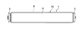
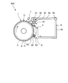
- FIG. 1 It is a side view of the cleaning unit which concerns on Embodiment 1 of this invention. It is a front view of the cleaning unit which concerns on Embodiment 1 of this invention. It is sectional drawing which shows the structure of the dust collector which concerns on Embodiment 1 of this invention. It is explanatory drawing explaining the diameter of the dust collector and outer ring which concern on Embodiment 1 of this invention. It is explanatory drawing explaining a dust collector and an outer ring
- (Embodiment 1) 1 to 6 are diagrams illustrating the configuration and operation of the cleaning unit according to the first embodiment.
- the cleaning unit 100 includes a dust collector 1 that conveys dust and the like on the surface and a drive device that drives the dust collector 1.
- the first removal mechanism 4 composed of, for example, a scraper for physically separating the outer rings 3 and 3 disposed on both side surfaces of the dust collector 1 and the dust attached to the surface of the dust collector 1.
- a recovery part 5 having an opening 51 for recovering dust and the like separated by the first removal mechanism 4, and provided in the opening 51 and rotated together with the dust collector 1 to collect the dust and the like.
- a rotating body 20 serving as a dust introduction member leading to the inside of the battery 5
- a charging device 6 for generating static electricity to charge the dust collector 1, and immediately before physically separating dust and the like from the surface of the dust collector 1. Further, it is constituted by a charge removing device 7 for removing the charge of the dust collector 1.
- FIG. 3 is a cross-sectional view showing the structure of the dust collector 1.
- the dust collector 1 has a cylindrical structure.
- the dust collector 1 includes a cylindrical member 13, an elastic layer 12 made of an elastic member such as rubber or sponge, formed on the outer periphery of the cylindrical member 13, and dust formed on the outer periphery of the elastic layer 12. It is formed on the outer periphery of the dust collection roller 10 composed of the dust collection layer 11 for adsorbing and the dust collection layer 11, and protects the dust collection layer 11 so that the dust collection layer 11 becomes dirty or damaged. And a cover 9 for preventing this.
- the dust collection layer 11 is a charge layer for charging electric charges, and is charged by a charging device 6 disposed in the vicinity of the dust collector 1 as shown in FIG.
- the charged dust collection layer 11 is cleaned by adsorbing dust or the like on the floor surface through the cover 9 due to static electricity.
- the dust collection layer As another structure of the dust collection layer, a structure in which dielectric polarization is caused by applying a voltage to a sheet-like member provided with an electrode pattern, thereby obtaining a force for adsorbing dust or the like may be used. Good.
- the method for adsorbing dust or the like of the dust collector 1 is not particularly limited.
- the cover 9 needs to be made of a material that transmits the adsorption force generated from the dust collection layer 11 to the dust on the floor, and has high wear resistance and high sliding because it comes into contact with the floor and dust. Is preferred. In consideration of such performance, the material and thickness of the cover 9 can be arbitrarily selected. However, since the suction force of the dust collector 1 decreases as the thickness of the cover 9 increases, a thickness of 0.2 mm or less is desirable.
- PU polyurethane
- PVC polyvinyl chloride
- ultra-high molecular weight polyethylene, or the like can be used, but is not limited thereto. Any material that satisfies the wearability and the like may be used.
- a rotating device 2 such as a motor is mounted inside the dust collector 1 as a drive device for driving the dust collector 1.
- a rotating device 2 such as a motor is mounted inside the dust collector 1 as a drive device for driving the dust collector 1.
- the rotating device 2 by mounting the rotating device 2 inside the dust collecting roller 10, it is possible to make it difficult for the user of the cleaning unit 100 to hear the rotating sound generated when the rotating device 2 rotates.
- the rotating device 2 is connected to the cylindrical member 13 of the dust collecting roller 10 via a bracket 41 and a flange 42 so that the dust collecting roller 10 can be rotated.
- the rotating device 2 takes a rotational reaction force by a support member (not shown), and as a power feeding method to the rotating device 2, a method of feeding power from the outside via the slip ring 8 is adopted.
- a method for supplying power to the rotating device 2 a rechargeable battery or a dry battery that can be mounted on a vacuum cleaner is preferable from the viewpoint of operability.
- the power supply method is not limited to this, and a wired method such as an outlet may be used.
- the collection unit 5 includes a collection unit main body 5 c and a top surface 5 a. One end of the top surface 5a is rotatably attached to the recovery unit main body 5c via a hinge 5b.
- the collection unit 5 has an opening 51.
- the opening 51 is provided between the other end portion of the top surface 5a and one end portion of the recovery portion main body 5c.
- One end of the first removal mechanism 4 is attached to one end of the recovery unit body 5c. The first removal mechanism 4 closes a part of the opening 51.
- the collection unit 5 is provided to be detachable from the cleaning unit 100. After removing the collection unit 5 from the cleaning unit 100, the top surface 5a of the collection unit 5 is opened and closed, whereby dust such as dust inside the collection unit 5 can be removed.
- the removal of dust such as dust is not limited to this method, and may be performed by opening and closing a part of the recovery unit main body 5c of the recovery unit 5, for example, the bottom surface or the rear part. On the other hand, it is excellent in that it is not necessary to detach it.
- the rotating body 20 has a cylindrical structure, and is formed of a cylindrical member 21 and an elastic member such as a sponge material such as urethane, a rubber material such as natural rubber, silicon, urethane, or an elastomer material on the outer periphery of the cylindrical member 21.
- the elastic layer 22 is provided.
- the rotating body 20 is disposed so as to contact the dust collector 1, the top surface 5 a of the collection unit 5, and the first removal mechanism 4 and close the opening 51.
- the rotating shaft of the rotating body 20 is supported so as to be rotatable on a side surface of the collecting unit 5 (not shown).
- the rotating body 20 rotates by receiving a rotational force from the dust collector 1.
- the dust collector 1 and the rotator 20 rotate at the same speed in the direction in which dust is sandwiched and sent out.
- the rotating body 20 may have a charge removal performance so that dust such as dust can be effectively removed by the first removal mechanism 4.
- the charging device 6 is made of a conductive cover 61 having an opening only on the surface facing the dust collector 1 and covering the other surface, a grid 63 attached to the opening facing the dust collector 1, and tungsten. And a corona wire 62 accommodated in the conductive cover 61. The corona wire 62 is held while being insulated from the conductive cover 61. By applying a voltage to the corona wire 62, static electricity can be generated in the dust collection layer 11 and the dust collection layer 11 can be charged.
- the outer ring 3 is disposed on both side surfaces of the dust collector 1 and can support the dust collector 1 in a partially rotatable manner.
- the outer ring 3 rotates freely with respect to the dust collector 1 whose rotation direction is determined by the rotating device 2.
- the dust collector 1 and the outer ring 3 are arranged concentrically.
- the outer ring 3 is fitted to a shaft 45 connected to the rotating device 2 via a bearing 46 so as to be rotatable in both directions.
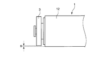
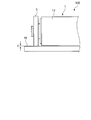
- the diameter of the dust collector 1 is not less than the diameter of the outer ring 3. Therefore, in a state where the elastic layer 12 constituting the dust collector 1 is not elastically deformed with no load, it is between the outer diameter of the dust collector 1 and the outer diameter of the outer ring 3 as shown in FIG. A gap B is generated. As shown in FIG. 5, when the cleaning unit 100 is installed on the floor surface 70, the elastic layer 12 is elastically deformed, and both the outer ring 3 and the dust collector 1 are in contact with the floor surface 70.
- the outer rings 3 and 3 support a part of the weight of the dust collector 1, the resistance due to friction between the floor surface 70 and the dust collector 1 is reduced, and the rotating device 2 is Such a load can be reduced.
- the elastic deformation of the elastic layer 12 limited to a certain limit by the outer rings 3 and 3 always maintains a stable contact state between the outer periphery of the dust collector 1 and the floor surface 70. On the other hand, stable adsorption performance can always be obtained.
- the diameter of the dust collector 1 may be equal to or smaller than the diameter of the outer ring 3.
- the positional relationship between the dust collector 1 and the floor surface 70 is defined by the outer rings 3 and 3, and a clearance C is provided between the dust collector 1 and the floor surface 70. Arise.
- the dust collector 1 is supported by the outer rings 3 and 3 so as not to contact the floor surface 70 and can always maintain a positional relationship with a certain clearance C with respect to the floor surface 70. Therefore, there is no load on the rotating device 2 due to the friction of the dust collector 1, and it is possible to always obtain a stable adsorption performance against the dust on the floor surface 70.
- the dust collector 1 since the dust collector 1 always has a certain clearance C with respect to the floor surface 70, the dust collector 1 does not contact the floor surface 70, and the load applied to the rotating device 2 is reduced. In addition, it is possible to obtain a stable adsorption performance against the dust on the floor surface 70 at all times.
- FIG. 7 is an explanatory diagram illustrating a collection method for the cleaning unit 100 to collect dust such as dust D.
- the dust collector 1 is rotated by the rotating device 2 in the direction of the arrow in the figure.
- Dust D and the like are recovered inside the recovery unit 5 by being physically blocked and separated from the outer peripheral surface of the cover 9 of the dust collector 1 by the first removal mechanism 4.
- the dust D or the like blocked here is scraped to the collection unit 5 side by the rotational movement of the rotating body 20 and is collected inside the collection unit 5.
- the charge removal device 7 removes the electric charge charged in the dust collection layer 11 of the dust collector 1, thereby removing the dust from the cover 9. D and the like can be easily removed.
- the charge removing device 7 is, for example, an LED (light emitting diode). This LED can remove charges by irradiating the dust collection layer 11 with light.
- the elastic layer 22 of the rotating body 20 is made of an elastic material, when the dust D or the like of various sizes is carried, the elastic layer 22 is flexibly deformed so that the dust D or the like is moved to the collection unit 5 side. It can be sent out, and dust such as dust D can be collected in the collection unit 5. Further, due to the elastic deformation of the elastic layer 22, the rotating body 20 can always maintain a stable and constant contact state with the dust collector 1, the top surface 5 a of the collection unit 5 and the first removal mechanism 4.
- the rotator 20 can guide the dust to the inside of the collection unit 5. Further, the rotating body 20 abuts on the top surface 5a of the collection unit 5 and the first removal mechanism 4 and closes the opening 51 of the collection unit 5, so that the dust collected inside the collection unit 5 is collected from the opening 51. Leakage to the outside of the part 5 can be prevented and dust can be reliably collected.
- an urging means such as a spring or rubber may be provided on the bearing portion of the rotator 20 so as to urge the rotator 20 in the normal direction of the dust collector 1.
- FIG. 8 is a diagram illustrating the configuration and operation of the cleaning unit 200 according to the second embodiment.
- the shape of the rotating body 30 as the dust introduction member is different.
- components that are the same as or similar to the components of the cleaning unit 100 of the first embodiment shown in FIGS. 1 to 7 are given the same reference numerals as those of the components of FIGS. Detailed description of their configuration and operation will be omitted.
- the rotating body 30 includes a cylindrical member 31 and six blades 32 that protrude radially outward from the outer peripheral surface of the cylindrical member 31 and are arranged at equal intervals in the circumferential direction. Yes.
- the six blades 32 each extend along a plane including the rotation axis of the rotating body 30.
- the tip portion of each blade 32 is in contact with the outer peripheral portion of the dust collector 1, transmits the rotational force from the dust collector 1 to the rotating body 30, and dust adsorbed on the outer peripheral surface of the cover 9 of the dust collector 1. D and the like are scraped to the collection unit 5 side.
- the blade 32 is made of an elastic member such as a sponge material such as urethane, a natural rubber, a rubber material such as silicon or urethane, or an elastomer material.
- the blade 32 can reliably guide the dust to the inside of the collecting unit 5. Therefore, it is possible to collect garbage more reliably.
- the six blades 32 each extend along a plane including the rotation axis of the rotator 30.
- the present invention is not limited to this, and the six blades 32 may extend spirally around the rotation axis. Since the tip of the blade 32 can always come into contact with the dust collector 1, the top surface 5 a of the collection unit 5 and the first removal mechanism 4, the rotational force from the dust collector 1 can be more reliably applied to the rotary body 30. In addition, the opening 51 of the collection unit 5 can be closed more reliably.
- FIG. 9 is a diagram illustrating the configuration and operation of the cleaning unit 300 according to the third embodiment. The difference from the second embodiment will be described.
- the third embodiment is different in that a second removal mechanism 14 for removing dust adhering to the blade 32 of the rotating body 30 is further provided.
- the same or similar components as those of the cleaning unit 200 of the second embodiment shown in FIG. 8 are denoted by the same reference numerals as those of the components of FIG. Detailed description of the configuration and operation is omitted.
- the second removal mechanism 14 is provided such that one end is attached to the top surface 5 a of the collection unit 5 and the other end is in contact with the tip of the blade 32 of the rotating body 30. It has been.
- the other end of the second removal mechanism 14 sequentially contacts the tip of the blade 32 as the rotating body 30 rotates. Thereby, the second removal mechanism 14 can effectively peel off dust, such as hair, attached to the tip of the blade 32 and scrape it toward the collection unit 5. Further, the second removal mechanism 14 can effectively block the opening 51 of the collection unit 5.
- the second removal mechanism 14 reliably guides the dust from the tip of the blade 32 to the inside of the collecting unit 5.
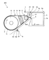
- FIG. 10 is a diagram illustrating the configuration and operation of the cleaning unit 400 of the fourth embodiment.
- the dust collector 410 includes a dust collecting roller 10 as an example of a first rotating body and a tension roller 17 as an example of a second rotating body. And a conveyor belt 15 wound around the dust collecting roller 10 and the tension roller 17 and having dust attached thereto.
- the same or similar components as those of the cleaning unit 100 of the first embodiment shown in FIGS. 1 to 7 are denoted by the same reference numerals as those of the components of FIGS. Detailed description of their configuration and operation will be omitted.
- the tension roller 17 is rotatably provided by a roller support member (not shown).
- the roller support member is locked and fixed by the support member 16.
- the conveyor belt 15 is driven by the rotation of the dust collection roller 10 and rotates around the dust collection roller 10 and the tension roller 17.
- the conveyor belt 15 needs to be made of a material that transmits the adsorption force generated from the dust collection layer 11 of the dust collection roller 10 to the dust on the floor surface, and has high wear resistance because it contacts the floor surface and dust. A thing with high slidability is preferable. Considering such performance, the material and thickness of the conveyor belt 15 can be arbitrarily selected. However, since the suction force of the dust collector 410 decreases as the thickness of the transport belt 15 increases, a thickness of 0.2 mm or less is desirable.
- polyurethane (PU), polyvinyl chloride (PVC), ultra-high molecular weight polyethylene, or the like can be used as the material constituting the conveyor belt 15, but is not limited thereto. Any material that satisfies the wear properties and the like may be used.
- the conveyor belt 15 is driven by the dust collecting roller 10 and rotates in the direction of the arrow in the figure.
- Dust D and the like are collected in the collection unit 5 by being physically blocked from the transport belt 15 by the first removal mechanism 4 and peeled off. At this time, since the dust D and the like are separated from the dust collection layer 11 of the dust collection roller 10, physical separation becomes easy. Furthermore, if the charge charged on the conveyor belt 15 is removed by the electrification removing device 7 or the like immediately before being transferred to the collection unit 5, dust D and the like can be more effectively separated from the conveyor belt 15. The peeled dust D and the like are finally collected by the collecting unit 5 as in the first to third embodiments.
- the conveyor belt 15 is wound around the dust collection roller 10 and the tension roller 17. Therefore, the conveyor belt 15 can be easily replaced by simply attaching and detaching the conveyor belt 15 to and from the dust collection roller 10 and the tension roller 17.
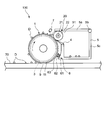
- FIG. 11 shows a cross-sectional view of the vacuum cleaner 500 of the fifth embodiment.
- This cleaner 500 uses the cleaning unit 100 of the first embodiment.
- a cleaning unit 100 and a battery 19 as an example of a power feeding device are mounted inside a housing (illustrated by a dotted line) 501 of the cleaner 500.
- the cleaner 500 functions.
- the cleaner 500 of the fifth embodiment includes the cleaning unit 100, the operation and effect of the cleaning unit 100 are exhibited.
- FIG. 12 shows a cross-sectional view of the vacuum cleaner 600 of the sixth embodiment. This vacuum cleaner 600 uses the cleaning unit 200 of the second embodiment.
- a cleaning unit 200 and a battery 19 as an example of a power feeding device are mounted inside a housing (illustrated by a dotted line) 601 of the cleaner 600.
- the vacuum cleaner 600 functions by supplying power from the battery 19 to the rotating device 2 of the cleaning unit 200.
- the cleaner 600 of the sixth embodiment has the cleaning unit 200, the operation and effect of the cleaning unit 200 are exhibited.
- FIG. 13 has shown sectional drawing of the cleaner 700 of Embodiment 7.
- FIG. This vacuum cleaner 700 uses the cleaning unit 300 of the third embodiment.
- a cleaning unit 300 and a battery 19 as an example of a power feeding device are mounted inside a casing (illustrated by a dotted line) 701 of the cleaner 700.
- the vacuum cleaner 700 functions by supplying power from the battery 19 to the rotating device 2 of the cleaning unit 300.
- the vacuum cleaner 700 of the seventh embodiment includes the cleaning unit 300, the operation and effect of the cleaning unit 300 are exhibited.
- FIG. 14 shows a cross-sectional view of the vacuum cleaner 800 of the eighth embodiment.
- This vacuum cleaner 800 uses the cleaning unit 400 of the fourth embodiment.
- a cleaning unit 400 and a battery 19 as an example of a power feeding device are mounted inside a housing (illustrated by a dotted line) 801 of the vacuum cleaner 800.
- the vacuum cleaner 800 functions by supplying power to the rotating device 2 of the cleaning unit 400 from the battery 19.
- the cleaner 800 of the eighth embodiment includes the cleaning unit 400, the operation and effect of the cleaning unit 400 are exhibited.
- the cleaning unit of the present invention is A dust collector 1,410 for carrying dust and conveying the dust, A driving device 2 for driving the dust collectors 1,410; A first removal mechanism 4 for removing dust adhering to the dust collectors 1,410; A collection unit 5 having an opening for collecting the dust removed by the first removal mechanism 4; It is provided so as to close the opening 51 of the recovery unit 5, and includes dust introduction members 20 and 30 that rotate together with the dust collectors 1 and 410 and guide dust to the inside of the recovery unit 5. .
- the dust introduction members 20 and 30 can block the opening 51 of the collection unit 5.
- the dust introduction members 20 and 30 rotate together with the dust collectors 1 and 410 to guide the dust into the collection unit 5. Therefore, the dust introduction members 20 and 30 can guide the dust to the inside of the collecting unit 5 and can prevent the dust from leaking from the opening 51 to the outside of the collecting unit 5, thereby reliably collecting the dust.
- the dust introduction members 20, 30 are Cylindrical members 21, 31; And an elastic layer 22 made of an elastic member provided on the outer periphery of the cylindrical members 21 and 31.
- the elastic layer 22 of the dust introduction member 20 is made of an elastic member, the elastic layer 22 is flexibly deformed when various sizes of dust are carried, and the dust is collected. 5 side can be sent out.
- the dust collectors 1,410 and the dust introduction members 20, 30 can always maintain a stable and constant contact state. For this reason, the opening 51 of the collection
- the dust introduction members 20, 30 are Cylindrical members 21, 31; A plurality of blades 32 provided on the outer periphery of the cylindrical members 21, 31; The plurality of blades 32 extend along a plane including the rotation axis of the dust introduction members 20 and 30.
- the plurality of blades 32 extend along a plane including the rotation axis of the dust introduction member 20, 30. For this reason, even when large and hard dust such as sand is carried, the blade 32 can reliably guide the dust to the inside of the collecting unit 5. Therefore, it is possible to collect garbage more reliably.
- the dust introduction members 20, 30 are Cylindrical members 21, 31; A plurality of blades 32 provided on the outer periphery of the cylindrical members 21, 31; The plurality of blades 32 extend spirally around the rotation shafts of the dust introduction members 20 and 30.
- the plurality of blades 32 extend spirally around the rotation shafts of the dust introduction members 20 and 30. For this reason, the blade 32 can always come into contact with the dust collectors 1,410, and the opening 51 of the collection unit 5 can be closed more reliably. Therefore, it is possible to prevent the dust collected inside the collection unit 5 from leaking from the opening 51 to the outside of the collection unit 5, and to collect the dust more reliably.
- the dust collectors 1,410 are A first rotating body 10; A second rotating body 17, The belt 15 is wound around the first rotating body 10 and the second rotating body 17 and adheres dust.
- the belt 15 is wound around the first rotating body 10 and the second rotating body 17. Therefore, the belt 15 can be easily replaced by simply attaching / detaching the belt 15 to / from the first rotating body 10 and the second rotating body 17.
- a second removal mechanism 14 is provided for removing dust adhering to the outer periphery of the dust introduction members 20 and 30.
- the second removal mechanism 14 can remove the dust attached to the outer periphery of the dust introduction members 10 and 20 and can effectively block the opening 51 of the collection unit 5. Accordingly, the dust can be reliably guided to the inside of the collecting unit 5 and the dust collected in the collecting unit 5 can be prevented from leaking from the opening 51 to the outside of the collecting unit 5. Can be recovered.
- the vacuum cleaner of the present invention The cleaning units 100, 200, 300, 400; And a power feeding device 19 for feeding power to the cleaning units 100, 200, 300, and 400.
- dust can be reliably guided to the inside of the collecting unit 5 and the dust collected inside the collecting unit 5 can be prevented from leaking from the opening 51 to the outside of the collecting unit 5. Can be collected reliably.
- the dust collectors 1 and 410 have a charging layer for charging electric charges.
- the present invention is not limited to this, and any structure that can adsorb dust may be used. .
- the rotary bodies 20 and 30 are in contact with the dust collectors 1 and 410.
- the present invention is not limited to this, and the rotary bodies 20 and 30 are provided separately from the dust collector and driven by a driving device. May be.
- the rotating bodies 20 and 30 are in contact with the top surface 5a of the recovery unit 5 and the first removal mechanism 4 to block the opening 51 of the recovery unit 5.
- the rotating body may close the opening of the collecting portion only by contacting the collecting portion, or the rotating body may contact the collecting portion, the first removing mechanism, and the dust collecting body to close the opening of the collecting portion. Further, the rotating body may not be in contact with the recovery unit and the first removal mechanism. At this time, for example, the rotating body is arranged so as to be slightly separated from the collection unit so that dust does not leak from the inside of the collection unit through the opening to the outside of the collection unit.
- the dust collector 1 has the cover 9, but the present invention is not limited to this.
- the dust collector may not have a cover, and dust may directly adhere to the dust collection layer of the dust collector.
- the rotating body 30 has the six blades 32.
- the rotating body may have 5 or less blades, and may have 7 or more blades.
Landscapes
- Engineering & Computer Science (AREA)
- Mechanical Engineering (AREA)
- Electrostatic Separation (AREA)
Abstract
掃除ユニットは、ゴミが付着すると共に、そのゴミを搬送する集塵体(1)と、集塵体(1)を駆動する駆動装置(2)と、集塵体(1)に付着したゴミを除去するための第1の除去機構(4)と、第1の除去機構(4)によって除去されたゴミを回収するための開口を有する回収部(5)と、回収部(5)の開口(51)を塞ぐように設けられ、集塵体(1)と共に回転して、ゴミを回収部(5)の内部に導くゴミ導入部材(20)とを備える。
Description
本発明は、掃除ユニット及びそれを利用した掃除機に関する。
従来技術の家庭用電気掃除機は、モーターによってファンを回転させて行う真空吸引方式が一般的である。他の従来技術としては、特許第3261342号公報(特許文献1)に記載の静電気を利用した静電掃除機がある。
この静電掃除機は、図15に示すように、帯電ローラー構造を採用している。帯電ローラー91を床面99上で転がすことにより、床面99上の埃等98を帯電ローラー91に吸着して、除去する。そして、帯電ローラー91で吸着した埃等98を回収する方法としては、スクレーパ92を帯電ローラー91に接触させることにより、帯電ローラー91上の埃等98を除去し、除去した埃等98を回収部93の開口95から回収部93の内部に回収する方法を採用している。
このため、前記静電掃除機は、真空吸引方式の掃除機のようにモーターやファンの回転による騒音が無く、また、排気による室内の空気の汚れが発生しないという利点がある。
しかしながら、従来の静電掃除機では、回収部93の開口95の一部がスクレーパ92によって塞がれているだけである。このため、例えば、前記掃除機の使用時または使用後に掃除機を移動させるとき、掃除機を持ち上げたり、使用者の意図しない方向に傾けたりすると、回収部93の内部に回収されたゴミが開口95から回収部93の外部に漏れ出すことがあるという問題がある。
そこで、本発明の課題は、回収部の内部に回収したゴミが回収部の外部に漏れ出すのを防止できて、ゴミを確実に回収できる掃除ユニットを提供することにある。
前記課題を解決するため、本発明の掃除ユニットは、
ゴミが付着すると共に、そのゴミを搬送する集塵体と、
前記集塵体を駆動する駆動装置と、
前記集塵体に付着したゴミを除去するための第1の除去機構と、
前記第1の除去機構によって除去されたゴミを回収するための開口を有する回収部と、
前記回収部の開口を塞ぐように設けられ、前記集塵体と共に回転して、ゴミを前記回収部の内部に導くゴミ導入部材と
を備えることを特徴としている。
ゴミが付着すると共に、そのゴミを搬送する集塵体と、
前記集塵体を駆動する駆動装置と、
前記集塵体に付着したゴミを除去するための第1の除去機構と、
前記第1の除去機構によって除去されたゴミを回収するための開口を有する回収部と、
前記回収部の開口を塞ぐように設けられ、前記集塵体と共に回転して、ゴミを前記回収部の内部に導くゴミ導入部材と
を備えることを特徴としている。
また、一実施形態の掃除ユニットでは、
前記ゴミ導入部材は、
円筒部材と、
その円筒部材の外周に設けられた弾性部材からなる弾性層とを有している。
前記ゴミ導入部材は、
円筒部材と、
その円筒部材の外周に設けられた弾性部材からなる弾性層とを有している。
また、一実施形態の掃除ユニットでは、
前記ゴミ導入部材は、
円筒部材と、
その円筒部材の外周に設けられた複数のブレードと
を有し、
前記複数のブレードは、前記ゴミ導入部材の回転軸を含む平面に沿って延びている。
前記ゴミ導入部材は、
円筒部材と、
その円筒部材の外周に設けられた複数のブレードと
を有し、
前記複数のブレードは、前記ゴミ導入部材の回転軸を含む平面に沿って延びている。
また、一実施形態の掃除ユニットでは、
前記ゴミ導入部材は、
円筒部材と、
その円筒部材の外周に設けられた複数のブレードと
を有し、
前記複数のブレードは、前記ゴミ導入部材の回転軸の周りに螺旋状に延びている。
前記ゴミ導入部材は、
円筒部材と、
その円筒部材の外周に設けられた複数のブレードと
を有し、
前記複数のブレードは、前記ゴミ導入部材の回転軸の周りに螺旋状に延びている。
また、一実施形態の掃除ユニットでは、
前記集塵体は、
第1の回転体と、
第2の回転体と、
前記第1の回転体と前記第2の回転体とに巻回されると共にゴミが付着するベルトと
で構成されている。
前記集塵体は、
第1の回転体と、
第2の回転体と、
前記第1の回転体と前記第2の回転体とに巻回されると共にゴミが付着するベルトと
で構成されている。
また、一実施形態の掃除ユニットでは、
前記ゴミ導入部材の外周に付着したゴミを除去するための第2の除去機構を備える。
前記ゴミ導入部材の外周に付着したゴミを除去するための第2の除去機構を備える。
本発明の掃除機は、
上述の掃除ユニットと、
前記掃除ユニットに給電する給電装置と
を備えることを特徴としている。
上述の掃除ユニットと、
前記掃除ユニットに給電する給電装置と
を備えることを特徴としている。
本発明によれば、ゴミ導入部材により、ゴミを回収部の内部に導くことができ、回収部の内部に回収したゴミが回収部の外部に漏れ出すのを防止できて、ゴミを確実に回収できる。
以下、本発明を図示の実施形態により詳細に説明する。なお、本明細書において、同一または類似の構成については、同一の参照符号を付している。
(実施形態1)
図1~6は、実施形態1の掃除ユニットの構成および動作を表す図である。
図1~6は、実施形態1の掃除ユニットの構成および動作を表す図である。
(掃除ユニット100の大略構成)
図1および2に示すように、この掃除ユニット100は、表面に床面の埃等が付着すると共に、その埃等を搬送する集塵体1と、この集塵体1を駆動する駆動装置と、集塵体1の両側面側に配置された外輪3,3と、集塵体1の表面に付着した埃等を物理的に剥離するための例えばスクレ-パからなる第1の除去機構4と、この第1の除去機構4によって剥離された埃等を回収するための開口51を有する回収部5と、この開口51に設けられ、集塵体1と共に回転して、埃等を回収部5の内部に導くゴミ導入部材としての回転体20と、静電気を発生させて集塵体1を帯電させるための帯電装置6と、埃等を集塵体1の表面から物理的に剥離する直前に、集塵体1の帯電を除去するための帯電除去装置7により構成されている。
図1および2に示すように、この掃除ユニット100は、表面に床面の埃等が付着すると共に、その埃等を搬送する集塵体1と、この集塵体1を駆動する駆動装置と、集塵体1の両側面側に配置された外輪3,3と、集塵体1の表面に付着した埃等を物理的に剥離するための例えばスクレ-パからなる第1の除去機構4と、この第1の除去機構4によって剥離された埃等を回収するための開口51を有する回収部5と、この開口51に設けられ、集塵体1と共に回転して、埃等を回収部5の内部に導くゴミ導入部材としての回転体20と、静電気を発生させて集塵体1を帯電させるための帯電装置6と、埃等を集塵体1の表面から物理的に剥離する直前に、集塵体1の帯電を除去するための帯電除去装置7により構成されている。
(集塵体1の構成)
図3は集塵体1の構造を示す断面図である。図3に示すように、この集塵体1は、円筒構造を有している。集塵体1は、円筒部材13と、この円筒部材13の外周に形成された、例えばゴムやスポンジ等の弾性部材からなる弾性層12と、この弾性層12の外周に形成された埃等を吸着するための集塵層11とで構成される集塵ローラー10と、前記集塵層11の外周に形成され、集塵層11を保護して、集塵層11が汚れたり、傷ついたりするのを防止するためのカバー9とを有している。
図3は集塵体1の構造を示す断面図である。図3に示すように、この集塵体1は、円筒構造を有している。集塵体1は、円筒部材13と、この円筒部材13の外周に形成された、例えばゴムやスポンジ等の弾性部材からなる弾性層12と、この弾性層12の外周に形成された埃等を吸着するための集塵層11とで構成される集塵ローラー10と、前記集塵層11の外周に形成され、集塵層11を保護して、集塵層11が汚れたり、傷ついたりするのを防止するためのカバー9とを有している。
(集塵層11の構成)
前記集塵層11は、電荷を帯電させるための帯電層となっており、図1に示すように、集塵体1の近傍に配置された帯電装置6により帯電させられる。帯電した集塵層11は、静電気により床面上の埃等をカバー9を介して吸着することで掃除を行う。
前記集塵層11は、電荷を帯電させるための帯電層となっており、図1に示すように、集塵体1の近傍に配置された帯電装置6により帯電させられる。帯電した集塵層11は、静電気により床面上の埃等をカバー9を介して吸着することで掃除を行う。
また、他の集塵層の構成としては、電極パターンを配設したシート状部材に電圧を印加することで誘電分極を起し、これにより埃等を吸着する力を得るものなどを用いてもよい。ここで、集塵体1の埃等を吸着する方式については、特に限定されるものではない。
(カバー9の構成)
カバー9は、集塵層11から発生する吸着力を床面のゴミに伝える材料からなる必要があり、また、床面やゴミと接触するため耐摩耗性の高いもの、摺動性が高いものが好ましい。このような性能を考慮すればカバー9の材質および厚みは任意に選ぶことができる。但し、カバー9の厚みが増すと集塵体1の吸着力が低下するため、0.2mm以下の厚みが望ましい。カバー9を構成する材料としては、例えば、ポリウレタン(PU)、ポリ塩化ビニル(PVC)、超高分子ポリエチレン等を用いることができるが、これらに限られず、集塵体1の吸着力や耐磨耗性などを満たす材料であればよい。
カバー9は、集塵層11から発生する吸着力を床面のゴミに伝える材料からなる必要があり、また、床面やゴミと接触するため耐摩耗性の高いもの、摺動性が高いものが好ましい。このような性能を考慮すればカバー9の材質および厚みは任意に選ぶことができる。但し、カバー9の厚みが増すと集塵体1の吸着力が低下するため、0.2mm以下の厚みが望ましい。カバー9を構成する材料としては、例えば、ポリウレタン(PU)、ポリ塩化ビニル(PVC)、超高分子ポリエチレン等を用いることができるが、これらに限られず、集塵体1の吸着力や耐磨耗性などを満たす材料であればよい。
(回転装置2の構成)
図3に示すように、前記集塵体1の内部には、この集塵体1を駆動する駆動装置として、例えばモーター等の回転装置2が搭載されている。このように、回転装置2を集塵ローラー10の内部に搭載することにより、回転装置2が回転するときに発生する回転音を掃除ユニット100の利用者等に聞こえ難くすることができる。
図3に示すように、前記集塵体1の内部には、この集塵体1を駆動する駆動装置として、例えばモーター等の回転装置2が搭載されている。このように、回転装置2を集塵ローラー10の内部に搭載することにより、回転装置2が回転するときに発生する回転音を掃除ユニット100の利用者等に聞こえ難くすることができる。
前記回転装置2は、ブラケット41、フランジ42を介して、集塵ローラー10の円筒部材13に連結していて、集塵ローラー10を回転させ得るようになっている。なお、前記回転装置2は、図示しない支持部材によって、回転反力をとっており、回転装置2への給電方法としては、スリップリング8を介して外部から給電する方法を採っている。ここで、回転装置2への給電方法としては、充電式のバッテリーや乾電池など掃除機に搭載可能なものが、操作性の観点より好ましい。しかしながら、給電方法はこれに限らず、コンセントなどの有線のものを用いても構わない。
(回収部5の構成)
図1に示すように、回収部5は、回収部本体5cおよび天面5aを有している。この天面5aの一端部は、回収部本体5cに対してヒンジ5bを介して回動可能に取り付けられている。回収部5は、開口51を有している。この開口51は、天面5aの他端部と回収部本体5cの一端部との間に設けられている。回収部本体5cの一端部には、前記第1の除去機構4の一端部が取り付けられている。第1の除去機構4は、開口51の一部を塞いでいる。
図1に示すように、回収部5は、回収部本体5cおよび天面5aを有している。この天面5aの一端部は、回収部本体5cに対してヒンジ5bを介して回動可能に取り付けられている。回収部5は、開口51を有している。この開口51は、天面5aの他端部と回収部本体5cの一端部との間に設けられている。回収部本体5cの一端部には、前記第1の除去機構4の一端部が取り付けられている。第1の除去機構4は、開口51の一部を塞いでいる。
回収部5は、掃除ユニット100に対して着脱可能に設けられている。回収部5を掃除ユニット100から取り外した後、回収部5の天面5aが開閉されることで、回収部5の内部の埃等のゴミを除去することができる。埃等のゴミ除去は、この方法に限らず、回収部5の回収部本体5cの一部、例えば底面や後部が開閉することでなされてもよく、この場合、回収部5を掃除ユニット100に対して着脱する必要がない点で優れている。
(回転体20の構成)
回転体20は、円筒構造を有し、円筒部材21と、この円筒部材21の外周に、例えばウレタンなどのスポンジ材や天然ゴムやシリコン、ウレタンなどのゴム材やエラストマー材料等の弾性部材で形成された弾性層22とを有している。回転体20は、集塵体1、回収部5の天面5aおよび第1の除去機構4と当接して、開口51を塞ぐように配置されている。回転体20の回転軸は、図示しない回収部5の側面にて回動可能なように支持されている。回転体20は、集塵体1から回転力を受けて回転する。集塵体1と回転体20は、埃等を挟み込み、送り出す方向に同じ速度で回転する。
回転体20は、円筒構造を有し、円筒部材21と、この円筒部材21の外周に、例えばウレタンなどのスポンジ材や天然ゴムやシリコン、ウレタンなどのゴム材やエラストマー材料等の弾性部材で形成された弾性層22とを有している。回転体20は、集塵体1、回収部5の天面5aおよび第1の除去機構4と当接して、開口51を塞ぐように配置されている。回転体20の回転軸は、図示しない回収部5の側面にて回動可能なように支持されている。回転体20は、集塵体1から回転力を受けて回転する。集塵体1と回転体20は、埃等を挟み込み、送り出す方向に同じ速度で回転する。
なお、回転体20に除電性能を持たせて、第1の除去機構4による埃等のゴミの除去を効果的に行えるようにしてもよい。
(帯電装置6の構成)
帯電装置6は、集塵体1に対向する面にのみ開口を有する一方その他の面を覆う導電カバー61と、前記集塵体1に対向する開口に取り付けたグリッド63と、タングステン等で作られ、導電カバー61に収納されたコロナワイヤ62とからなる。このコロナワイヤ62は導電カバー61と絶縁を保ちつつ保持されている。コロナワイヤ62に電圧を印可することにより、集塵層11に静電気を発生させ、集塵層11を帯電させることができる。
帯電装置6は、集塵体1に対向する面にのみ開口を有する一方その他の面を覆う導電カバー61と、前記集塵体1に対向する開口に取り付けたグリッド63と、タングステン等で作られ、導電カバー61に収納されたコロナワイヤ62とからなる。このコロナワイヤ62は導電カバー61と絶縁を保ちつつ保持されている。コロナワイヤ62に電圧を印可することにより、集塵層11に静電気を発生させ、集塵層11を帯電させることができる。
(外輪3の構成)
図2および3に示すように、前記外輪3は、集塵体1の両側面側に配置されていて、集塵体1を部分的に回転自在に支持可能である。回転装置2によって回転方向が決められている集塵体1に対し、外輪3は自由に回転する。集塵体1と外輪3は、同心に配置されている。前記外輪3は、回転装置2に連なる軸45に、ベアリング46を介して、両方向に回転自在に嵌合している。
図2および3に示すように、前記外輪3は、集塵体1の両側面側に配置されていて、集塵体1を部分的に回転自在に支持可能である。回転装置2によって回転方向が決められている集塵体1に対し、外輪3は自由に回転する。集塵体1と外輪3は、同心に配置されている。前記外輪3は、回転装置2に連なる軸45に、ベアリング46を介して、両方向に回転自在に嵌合している。
図4および5に示すように、集塵体1の直径は、外輪3の直径以上の大きさとしている。そのため、集塵体1を構成している弾性層12が無負荷で弾性変形していない状態では、図4に示すように、集塵体1の外径と外輪3の外径との間に隙間Bが生じる。そして、図5に示すように、掃除ユニット100を床面70に設置した場合、弾性層12が弾性変形し、外輪3、集塵体1が共に床面70に接触する。
もし、前記外輪3が無いと仮定すると、集塵体1の自重が直接床面70にかかるため、回転時において、床面70と集塵体1との摩擦による大きな負荷が回転装置2にかかることになる。
本実施形態1では、外輪3,3が、集塵体1の自重の一部を支持しているから、床面70と集塵体1との摩擦による抵抗が小さくなって、回転装置2にかかる負荷を低減することができる。
また、前記外輪3,3により一定限度に制限された弾性層12の弾性変形により、集塵体1の外周と床面70とは常に安定した接触状態を維持するため、床面70の埃に対して常に安定した吸着性能を得ることができる。
なお、図6に示すように、集塵体1の直径を外輪3の直径以下としてもよい。掃除ユニット100を床面70に設置した場合、集塵体1と床面70との位置関係は、外輪3,3により規定されて、集塵体1と床面70との間にクリアランスCが生じる。
したがって、前記集塵体1は、外輪3,3に支持されて、床面70に接触しないで、かつ、床面70に対して一定のクリアランスCをもつ位置関係を常に保つことが可能であるため、集塵体1の摩擦による回転装置2への負荷がなく、また、床面70の埃に対して常に安定した吸着性能を得ることが可能である。
すなわち、集塵体1が床面70に対して常に一定のクリアランスCをもつているため、集塵体1が床面70に接触することがなくて、回転装置2にかかる負荷を低減することができ、かつ、床面70の埃に対して常に安定した吸着性能を得ることができる。
(埃等の回収方法)
図7は、掃除ユニット100が埃D等のゴミを回収するための回収方法について説明する説明図である。
図7は、掃除ユニット100が埃D等のゴミを回収するための回収方法について説明する説明図である。
図7に示すように、前記集塵体1は、回転装置2によって図中矢印の方向に回転する。
前記集塵ローラー10の集塵層11が帯電されたことにより、カバー9の外周面に床面の埃D等が吸着する。集塵体1の回転により、吸着された埃D等は、回収部5に向けて移送される。
埃D等は、集塵体1のカバー9の外周面から第1の除去機構4により物理的に塞ぎ止められると共に剥離されることで、回収部5の内部に回収される。ここで塞ぎ止められた埃D等は、回転体20の回転運動により、回収部5側へ掻き出されて、回収部5の内部に回収される。
ここで、埃D等が第1の除去機構4に移送される直前に、帯電除去装置7により集塵体1の集塵層11に帯電している電荷を除去することで、カバー9から埃D等を簡単に除去することができる。
前記帯電除去装置7は、例えばLED(発光ダイオード)である。このLEDが、集塵層11に対して光を照射することにより、電荷を除去することができる。
回転体20の弾性層22は、弾性材料より成るため、さまざまなサイズの埃D等が運ばれて来た際に、弾性層22が柔軟に変形することで埃D等を回収部5側へ送り出すことができ、回収部5の内部に埃D等のゴミを回収できる。また、弾性層22の弾性変形により、回転体20は、集塵体1、回収部5の天面5aおよび第1の除去機構4と常に安定した一定の接触状態を維持できる。
本実施形態1によれば、回転体20によって、ゴミを回収部5の内部に導くことができる。また、回転体20は、回収部5の天面5aおよび第1の除去機構4と当接して、回収部5の開口51を塞ぐので、回収部5の内部に回収したゴミが開口51から回収部5の外部に漏れ出すのを防止できて、ゴミを確実に回収できる。
なお、回転体20を集塵体1の法線方向に付勢するように、回転体20の軸受け部にバネやゴムといった付勢手段を設けてもよい。この付勢手段により、埃D等のゴミが搬送されていない間、集塵体1と回転体20とは当接するため、回収部5の開口51をより確実に塞ぐことができる。また、様々な大きさのゴミの搬送にも対応することができる。
(実施形態2)
図8は、実施形態2の掃除ユニット200の構成および動作を示す図である。実施形態1と相違する点を説明すると、この実施形態2では、ゴミ導入部材としての回転体30の形状が相違する。なお、図8において、図1~7に示す実施形態1の掃除ユニット100の構成部と同一または類似の構成部については、図1~7の構成部の参照番号と同一の参照番号を付して、それらの構成および作用の詳細な説明を省略する。
図8は、実施形態2の掃除ユニット200の構成および動作を示す図である。実施形態1と相違する点を説明すると、この実施形態2では、ゴミ導入部材としての回転体30の形状が相違する。なお、図8において、図1~7に示す実施形態1の掃除ユニット100の構成部と同一または類似の構成部については、図1~7の構成部の参照番号と同一の参照番号を付して、それらの構成および作用の詳細な説明を省略する。
(回転体30の構成)
図8に示すように、回転体30は、円筒部材31と、この円筒部材31の外周面から径方向外側に突出すると共に周方向に等間隔に配列された6つのブレード32とを有している。
図8に示すように、回転体30は、円筒部材31と、この円筒部材31の外周面から径方向外側に突出すると共に周方向に等間隔に配列された6つのブレード32とを有している。
6つのブレード32は、回転体30の回転軸を含む平面に沿ってそれぞれ延びている。各ブレード32の先端部は、集塵体1の外周部と当接し、集塵体1からの回転力を回転体30に伝えると共に、集塵体1のカバー9の外周面に吸着された埃D等を回収部5側へ掻き出す。ブレード32は、例えばウレタンなどのスポンジ材や天然ゴムやシリコン、ウレタンなどのゴム材やエラストマー材料等の弾性部材で構成されている。
本実施形態によれば、砂等の大きく、硬いゴミが運ばれてきた場合においても、ブレード32によって、ゴミを確実に回収部5の内部に導くことができる。したがって、ゴミをより確実に回収できる。
なお、6つのブレード32は、回転体30の回転軸を含む平面に沿ってそれぞれ延びていたが、これに限らず、前記回転軸の周りに螺旋状に延びていてもよい。ブレード32の先端部が集塵体1、回収部5の天面5aおよび第1の除去機構4と常に当接するようにできるので、集塵体1からの回転力をより確実に回転体30に伝えると共に、回収部5の開口51をより確実に塞ぐことができる。
(実施形態3)
図9は、実施形態3の掃除ユニット300の構成および動作を示す図である。実施形態2と相違する点を説明すると、この実施形態3では、回転体30のブレード32に付着したゴミを除去するための第2の除去機構14が更に設けられている点が相違する。なお、図9において、図8に示す実施形態2の掃除ユニット200の構成部と同一または類似の構成部については、図8の構成部の参照番号と同一の参照番号を付して、それらの構成および作用の詳細な説明を省略する。
図9は、実施形態3の掃除ユニット300の構成および動作を示す図である。実施形態2と相違する点を説明すると、この実施形態3では、回転体30のブレード32に付着したゴミを除去するための第2の除去機構14が更に設けられている点が相違する。なお、図9において、図8に示す実施形態2の掃除ユニット200の構成部と同一または類似の構成部については、図8の構成部の参照番号と同一の参照番号を付して、それらの構成および作用の詳細な説明を省略する。
(第2の除去機構14の構成、および、機能)
図9に示すように、第2の除去機構14は、一端部が回収部5の天面5aに取り付けられる一方、他端部が、回転体30のブレード32の先端部と接触するように設けられている。
図9に示すように、第2の除去機構14は、一端部が回収部5の天面5aに取り付けられる一方、他端部が、回転体30のブレード32の先端部と接触するように設けられている。
第2の除去機構14の他端部は、回転体30の回転に伴って、ブレード32の先端部と順次接触する。これにより、第2の除去機構14は、ブレード32の先端部に付着している、例えば毛髪等のゴミを効果的に剥し取り、回収部5側へ掻き出すことができる。また、第2の除去機構14は、回収部5の開口51を効果的に塞ぐことができる。
本実施形態によれば、回転体30のブレード32の先端部にゴミが付着しても、第2の除去機構14によって、ブレード32の先端部からゴミを確実に回収部5の内部に導くことができ、かつ、回収部5の内部に回収したゴミが開口51から回収部5の外部に漏れ出すのを防止できて、ゴミをより確実に回収できる。特に、ブレード32の先端部に付着している毛髪等のゴミを確実に回収して、毛髪等のゴミが回転体30に絡み付くのを防止できる。
(実施形態4)
図10は、実施形態4の掃除ユニット400の構成および動作を示す図である。実施形態1と相違する点を説明すると、この実施形態4では、集塵体410が、第1の回転体の一例としての集塵ローラー10と、第2の回転体の一例としてのテンションローラー17と、集塵ローラー10とテンションローラー17とに巻回されると共にゴミが付着する搬送ベルト15とで構成されている点が相違する。なお、図10において、図1~7に示す実施形態1の掃除ユニット100の構成部と同一または類似の構成部については、図1~7の構成部の参照番号と同一の参照番号を付して、それらの構成および作用の詳細な説明を省略する。
図10は、実施形態4の掃除ユニット400の構成および動作を示す図である。実施形態1と相違する点を説明すると、この実施形態4では、集塵体410が、第1の回転体の一例としての集塵ローラー10と、第2の回転体の一例としてのテンションローラー17と、集塵ローラー10とテンションローラー17とに巻回されると共にゴミが付着する搬送ベルト15とで構成されている点が相違する。なお、図10において、図1~7に示す実施形態1の掃除ユニット100の構成部と同一または類似の構成部については、図1~7の構成部の参照番号と同一の参照番号を付して、それらの構成および作用の詳細な説明を省略する。
(集塵体410の構成)
図10に示すように、テンションローラー17は、図示しないローラー支持部材によって回動可能に設けられている。このローラー支持部材は、支持部材16により、係止され、固定されている。搬送ベルト15は、集塵ローラー10の回転によって駆動されて、集塵ローラー10およびテンションローラー17の周りを回転する。
図10に示すように、テンションローラー17は、図示しないローラー支持部材によって回動可能に設けられている。このローラー支持部材は、支持部材16により、係止され、固定されている。搬送ベルト15は、集塵ローラー10の回転によって駆動されて、集塵ローラー10およびテンションローラー17の周りを回転する。
(搬送ベルト15の構成)
搬送ベルト15は、集塵ローラー10の集塵層11から発生する吸着力を床面のゴミに伝える材料からなる必要があり、また、床面やゴミと接触するため耐摩耗性の高いもの、摺動性が高いものが好ましい。このような性能を考慮すれば搬送ベルト15の材質および厚みは任意に選ぶことができる。但し、搬送ベルト15の厚みが増すと集塵体410の吸着力が低下するため、0.2mm以下の厚みが望ましい。搬送ベルト15を構成する材料としては、例えば、ポリウレタン(PU)、ポリ塩化ビニル(PVC)、超高分子ポリエチレン等を用いることができるが、これらに限られず、集塵体410の吸着力や耐磨耗性などを満たす材料であればよい。
搬送ベルト15は、集塵ローラー10の集塵層11から発生する吸着力を床面のゴミに伝える材料からなる必要があり、また、床面やゴミと接触するため耐摩耗性の高いもの、摺動性が高いものが好ましい。このような性能を考慮すれば搬送ベルト15の材質および厚みは任意に選ぶことができる。但し、搬送ベルト15の厚みが増すと集塵体410の吸着力が低下するため、0.2mm以下の厚みが望ましい。搬送ベルト15を構成する材料としては、例えば、ポリウレタン(PU)、ポリ塩化ビニル(PVC)、超高分子ポリエチレン等を用いることができるが、これらに限られず、集塵体410の吸着力や耐磨耗性などを満たす材料であればよい。
(埃等の回収方法)
前記搬送ベルト15は、集塵ローラー10によって駆動され、図中矢印の方向に回転する。
前記搬送ベルト15は、集塵ローラー10によって駆動され、図中矢印の方向に回転する。
前記集塵ローラー10の集塵層11が帯電装置6によって帯電されたことにより、搬送ベルト15を介して搬送ベルト15の外周面に床面の埃D等が吸着する。搬送ベルト15の回転により、搬送ベルト15の外周面に吸着された埃D等は、順次、回収部5に向けて移送される。
埃D等は、搬送ベルト15から第1の除去機構4により物理的に塞ぎ止められると共に剥離されることで、回収部5の内部に回収される。このとき、埃D等は、集塵ローラー10の集塵層11とは離間しているため、物理的な剥離が容易になる。さらには、回収部5に移送される直前に、帯電除去装置7などにより、搬送ベルト15に帯電している電荷を除去すれば、さらに効果的に搬送ベルト15から埃D等を剥離できる。剥離された埃D等は、実施形態1~3と同様に最終的に回収部5に回収される。
本実施形態4によれば、搬送ベルト15は、集塵ローラー10とテンションローラー17とに巻回されている。したがって、搬送ベルト15を集塵ローラー10およびテンションローラー17に対して着脱するだけで、搬送ベルト15を簡単に交換できる。
(実施形態5)
図11は、実施形態5の掃除機500の断面図を示している。この掃除機500は、実施形態1の掃除ユニット100を使用している。
図11は、実施形態5の掃除機500の断面図を示している。この掃除機500は、実施形態1の掃除ユニット100を使用している。
図11に示すように、掃除機500の筐体(点線で図示)501の内部には、掃除ユニット100および給電装置の一例としてのバッテリー19が搭載されている。
前記バッテリー19より掃除ユニット100の回転装置2に対して給電することにより、掃除機500が機能する。
また、本実施形態5の掃除機500は、前記掃除ユニット100を有するので、掃除ユニット100の作用、効果を奏する。
(実施形態6)
図12は、実施形態6の掃除機600の断面図を示している。この掃除機600は、実施形態2の掃除ユニット200を使用している。
図12は、実施形態6の掃除機600の断面図を示している。この掃除機600は、実施形態2の掃除ユニット200を使用している。
図12に示すように、掃除機600の筐体(点線で図示)601の内部には、掃除ユニット200および給電装置の一例としてのバッテリー19が搭載されている。
前記バッテリー19より掃除ユニット200の回転装置2に対して給電することにより、掃除機600が機能する。
また、本実施形態6の掃除機600は、前記掃除ユニット200を有するので、掃除ユニット200の作用、効果を奏する。
(実施形態7)
図13は、実施形態7の掃除機700の断面図を示している。この掃除機700は、実施形態3の掃除ユニット300を使用している。
図13は、実施形態7の掃除機700の断面図を示している。この掃除機700は、実施形態3の掃除ユニット300を使用している。
図13に示すように、掃除機700の筐体(点線で図示)701の内部には、掃除ユニット300および給電装置の一例としてのバッテリー19が搭載されている。
前記バッテリー19より掃除ユニット300の回転装置2に対して給電することにより、掃除機700が機能する。
また、本実施形態7の掃除機700は、前記掃除ユニット300を有するので、掃除ユニット300の作用、効果を奏する。
(実施形態8)
図14は、実施形態8の掃除機800の断面図を示している。この掃除機800は、実施形態4の掃除ユニット400を使用している。
図14は、実施形態8の掃除機800の断面図を示している。この掃除機800は、実施形態4の掃除ユニット400を使用している。
図14に示すように、掃除機800の筐体(点線で図示)801の内部には、掃除ユニット400および給電装置の一例としてのバッテリー19が搭載されている。
前記バッテリー19より掃除ユニット400の回転装置2に対して給電することにより、掃除機800が機能する。
また、本実施形態8の掃除機800は、前記掃除ユニット400を有するので、掃除ユニット400の作用、効果を奏する。
本発明および実施形態を纏めると、次のようになる。
本発明の掃除ユニットは、
ゴミが付着すると共に、そのゴミを搬送する集塵体1,410と、
前記集塵体1,410を駆動する駆動装置2と、
前記集塵体1,410に付着したゴミを除去するための第1の除去機構4と、
前記第1の除去機構4によって除去されたゴミを回収するための開口を有する回収部5と、
前記回収部5の開口51を塞ぐように設けられ、前記集塵体1,410と共に回転して、ゴミを前記回収部5の内部に導くゴミ導入部材20,30と
を備えることを特徴としている。
ゴミが付着すると共に、そのゴミを搬送する集塵体1,410と、
前記集塵体1,410を駆動する駆動装置2と、
前記集塵体1,410に付着したゴミを除去するための第1の除去機構4と、
前記第1の除去機構4によって除去されたゴミを回収するための開口を有する回収部5と、
前記回収部5の開口51を塞ぐように設けられ、前記集塵体1,410と共に回転して、ゴミを前記回収部5の内部に導くゴミ導入部材20,30と
を備えることを特徴としている。
前記構成の掃除ユニットによれば、ゴミ導入部材20,30は、回収部5の開口51を塞ぐことができる。ゴミ導入部材20,30は、集塵体1,410と共に回転して、ゴミを回収部5の内部に導く。したがって、ゴミ導入部材20,30によって、回収部5の内部にゴミを導くと共に、開口51から回収部5の外部にゴミが漏れ出すのを防止できて、ゴミを確実に回収できる。
1実施形態では、
前記ゴミ導入部材20,30は、
円筒部材21,31と、
その円筒部材21,31の外周に設けられた弾性部材からなる弾性層22とを有している。
前記ゴミ導入部材20,30は、
円筒部材21,31と、
その円筒部材21,31の外周に設けられた弾性部材からなる弾性層22とを有している。
前記実施形態によれば、ゴミ導入部材20の弾性層22は、弾性部材からなるので、さまざまなサイズのゴミが運ばれて来た際に弾性層22が柔軟に変形して、ゴミを回収部5側へ送り出すことができる。
また、弾性層22の弾性変形により、集塵体1,410とゴミ導入部材20,30とは常に安定した一定の接触状態を維持できる。このため、回収部5の開口51をより確実に塞ぐことができる。したがって、回収部5の内部に回収したゴミが開口51から回収部5の外部に漏れ出すのを防止できて、ゴミをより確実に回収できる。
また、1実施形態では、
前記ゴミ導入部材20,30は、
円筒部材21,31と、
前記円筒部材21,31の外周に設けられた複数のブレード32と
を有し、
前記複数のブレード32は、前記ゴミ導入部材20,30の回転軸を含む平面に沿って延びている。
前記ゴミ導入部材20,30は、
円筒部材21,31と、
前記円筒部材21,31の外周に設けられた複数のブレード32と
を有し、
前記複数のブレード32は、前記ゴミ導入部材20,30の回転軸を含む平面に沿って延びている。
前記実施形態によれば、複数のブレード32は、前記ゴミ導入部材20,30の回転軸を含む平面に沿って延びている。このため、砂等の大きく、硬いゴミが運ばれてきた場合においても、ブレード32によって、ゴミを確実に回収部5の内部に導くことができる。したがって、ゴミをより確実に回収できる。
また、1実施形態では、
前記ゴミ導入部材20,30は、
円筒部材21,31と、
前記円筒部材21,31の外周に設けられた複数のブレード32と
を有し、
前記複数のブレード32は、前記ゴミ導入部材20,30の回転軸の周りに螺旋状に延びている。
前記ゴミ導入部材20,30は、
円筒部材21,31と、
前記円筒部材21,31の外周に設けられた複数のブレード32と
を有し、
前記複数のブレード32は、前記ゴミ導入部材20,30の回転軸の周りに螺旋状に延びている。
前記実施形態によれば、複数のブレード32は、前記ゴミ導入部材20,30の回転軸の周りに螺旋状に延びている。このため、ブレード32が集塵体1,410と常に当接できて、回収部5の開口51をより確実に塞ぐことができる。したがって、回収部5の内部に回収したゴミが開口51から回収部5の外部に漏れ出すのを防止できて、ゴミをより確実に回収できる。
また、1実施形態では、
前記集塵体1,410は、
第1の回転体10と、
第2の回転体17と、
前記第1の回転体10と前記第2の回転体17とに巻回されると共にゴミが付着するベルト15と
で構成されている。
前記集塵体1,410は、
第1の回転体10と、
第2の回転体17と、
前記第1の回転体10と前記第2の回転体17とに巻回されると共にゴミが付着するベルト15と
で構成されている。
前記実施形態によれば、ベルト15は、第1の回転体10と第2の回転体17とに巻回されている。したがって、ベルト15を第1の回転体10および第2の回転体17に対して着脱するだけで、ベルト15を簡単に交換できる。
また、1実施形態では、
前記ゴミ導入部材20,30の外周に付着したゴミを除去するための第2の除去機構14を備える。
前記ゴミ導入部材20,30の外周に付着したゴミを除去するための第2の除去機構14を備える。
前記実施形態によれば、第2の除去機構14は、ゴミ導入部材10,20の外周に付着したゴミを除去すると共に、回収部5の開口51を効果的に塞ぐことができる。したがって、ゴミを確実に回収部5の内部に導くことができ、かつ、回収部5の内部に回収したゴミが開口51から回収部5の外部に漏れ出すのを防止できて、ゴミをより確実に回収できる。
また、本発明の掃除機は、
前記掃除ユニット100,200,300,400と、
前記掃除ユニット100,200,300,400に給電する給電装置19と
を備える。
前記掃除ユニット100,200,300,400と、
前記掃除ユニット100,200,300,400に給電する給電装置19と
を備える。
本発明の掃除機によれば、ゴミを確実に回収部5の内部に導くことができ、かつ、回収部5の内部に回収したゴミが開口51から回収部5の外部に漏れ出すのを防止できて、ゴミを確実に回収できる。
なお、本発明の実施形態1~4では、集塵体1,410は、電荷を帯電させるための帯電層を有していたが、これに限らず、ゴミを吸着可能な構造であればよい。
また、前記実施形態1~4では、回転体20,30は、集塵体1,410と当接していたが、これに限らず、集塵体と離隔して設けられ、駆動装置によって駆動されてもよい。
また、前記実施形態1~4では、回転体20,30は、回収部5の天面5aおよび第1の除去機構4と当接して、回収部5の開口51を塞いでいたが、これに限られない。回転体が回収部と当接するだけで、回収部の開口を塞いでもよいし、回転体が回収部と第1の除去機構と集塵体と当接して、回収部の開口を塞いでもよい。また、回転体は、回収部および第1の除去機構と当接していなくてもよい。このとき、例えば、回収部の内部から開口を通って回収部の外部にゴミが漏れ出ない程度に、回転体を回収部に対してわずかに離隔するように配置する。
また、前記実施形態1~3では、集塵体1は、カバー9を有していたが、これに限られない。集塵体がカバーを有さず、ゴミが集塵体の集塵層に直接、付着するようにしてもよい。
また、前記実施形態2および3では、回転体30は、6つのブレード32を有していたが、これに限られない。回転体は、5つ以下のブレードを有していてもよいし、7つ以上のブレードを有していてもよい。
実施形態1~4および変形例で述べた構成要素は、適宜、組み合わせてもよく、また、適宜、選択、置換、あるいは、削除してもよいのは、勿論である。
1,410 集塵体
2 回転装置
4 第1の除去機構
5 回収部
8 スリップリング
9 カバー
10 集塵ローラー
11 集塵層
12 弾性層
13 円筒部材
14 第2の除去機構
15 搬送ベルト
17 テンションローラー
19 バッテリー
20,30 回転体
21,31 円筒部材
22 弾性層
32 ブレード
51 開口
100,200,300,400 掃除ユニット
500,600,700,800 掃除機
2 回転装置
4 第1の除去機構
5 回収部
8 スリップリング
9 カバー
10 集塵ローラー
11 集塵層
12 弾性層
13 円筒部材
14 第2の除去機構
15 搬送ベルト
17 テンションローラー
19 バッテリー
20,30 回転体
21,31 円筒部材
22 弾性層
32 ブレード
51 開口
100,200,300,400 掃除ユニット
500,600,700,800 掃除機
Claims (7)
- ゴミが付着すると共に、そのゴミを搬送する集塵体(1,410)と、
前記集塵体(1,410)を駆動する駆動装置(2)と、
前記集塵体(1,410)に付着したゴミを除去するための第1の除去機構(4)と、
前記第1の除去機構(4)によって除去されたゴミを回収するための開口を有する回収部(5)と、
前記回収部(5)の開口(51)を塞ぐように設けられ、前記集塵体(1,410)と共に回転して、ゴミを前記回収部(5)の内部に導くゴミ導入部材(20,30)と
を備えることを特徴とする掃除ユニット。 - 請求項1に記載の掃除ユニットにおいて、
前記ゴミ導入部材(20,30)は、
円筒部材(21,31)と、
その円筒部材(21,31)の外周に設けられた弾性部材からなる弾性層(22)と
を有していることを特徴とする掃除ユニット。 - 請求項1に記載の掃除ユニットにおいて、
前記ゴミ導入部材(20,30)は、
円筒部材(21,31)と、
その円筒部材(21,31)の外周に設けられた複数のブレード(32)と
を有し、
前記複数のブレード(32)は、前記ゴミ導入部材(20,30)の回転軸を含む平面に沿って延びていることを特徴とする掃除ユニット。 - 請求項1に記載の掃除ユニットにおいて、
前記ゴミ導入部材(20,30)は、
円筒部材(21,31)と、
その円筒部材(21,31)の外周に設けられた複数のブレード(32)と
を有し、
前記複数のブレード(32)は、前記ゴミ導入部材(20,30)の回転軸の周りに螺旋状に延びていることを特徴とする掃除ユニット。 - 請求項1から4のいずれか1つに記載の掃除ユニットにおいて、
前記集塵体(1,410)は、
第1の回転体(10)と、
第2の回転体(17)と、
前記第1の回転体(10)と前記第2の回転体(17)とに巻回されると共にゴミが付着するベルト(15)と
で構成されていることを特徴とする掃除ユニット。 - 請求項1から5のいずれか1つに記載の掃除ユニットにおいて、
前記ゴミ導入部材(20,30)の外周に付着したゴミを除去するための第2の除去機構(14)を備えることを特徴とする掃除ユニット。 - 請求項1から6のいずれか1つに記載の掃除ユニット(100,200,300,400)と、
前記掃除ユニット(100,200,300,400)に給電する給電装置(19)と
を備えることを特徴とする掃除機。
Applications Claiming Priority (2)
| Application Number | Priority Date | Filing Date | Title |
|---|---|---|---|
| JP2014052458A JP5747097B1 (ja) | 2014-03-14 | 2014-03-14 | 掃除ユニット及びそれを利用した掃除機 |
| JP2014-052458 | 2014-03-14 |
Publications (1)
| Publication Number | Publication Date |
|---|---|
| WO2015136772A1 true WO2015136772A1 (ja) | 2015-09-17 |
Family
ID=53537873
Family Applications (1)
| Application Number | Title | Priority Date | Filing Date |
|---|---|---|---|
| PCT/JP2014/079489 Ceased WO2015136772A1 (ja) | 2014-03-14 | 2014-11-06 | 掃除ユニット及びそれを利用した掃除機 |
Country Status (2)
| Country | Link |
|---|---|
| JP (1) | JP5747097B1 (ja) |
| WO (1) | WO2015136772A1 (ja) |
Families Citing this family (6)
| Publication number | Priority date | Publication date | Assignee | Title |
|---|---|---|---|---|
| JP6485851B2 (ja) * | 2014-07-04 | 2019-03-20 | 株式会社コーワ | 清掃具 |
| JP5809737B1 (ja) * | 2014-07-22 | 2015-11-11 | シャープ株式会社 | 掃除ユニット及びそれを利用した掃除機 |
| JP5807097B1 (ja) * | 2014-07-24 | 2015-11-10 | シャープ株式会社 | 掃除ユニット及びそれを利用した掃除機 |
| JP5842042B1 (ja) * | 2014-09-22 | 2016-01-13 | シャープ株式会社 | 掃除ユニット及びそれを利用した掃除機 |
| CN113425200B (zh) * | 2021-06-17 | 2022-05-13 | 佛山市顺德区兆之泓电器有限公司 | 一种智能家居多用途电动拖把 |
| WO2025146826A1 (ja) * | 2024-01-06 | 2025-07-10 | 株式会社クリエイティブテクノロジー | 静電クリーナー |
Citations (5)
| Publication number | Priority date | Publication date | Assignee | Title |
|---|---|---|---|---|
| JPS60156897U (ja) * | 1984-03-26 | 1985-10-18 | 株式会社明電舎 | マニプレ−タ用サ−ボモ−タ駆動装置 |
| JPH1156731A (ja) * | 1997-08-22 | 1999-03-02 | Matsushita Electric Ind Co Ltd | 静電集塵機 |
| JP2003093921A (ja) * | 2001-09-27 | 2003-04-02 | Yoshihisa Onda | 静電自動集塵装置 |
| EP1974644A2 (de) * | 2007-03-29 | 2008-10-01 | Fakir Hausgeräte GmbH | Reinigungsgerät zur Aufnahme von partikulärem Schmutz |
| WO2012129541A2 (en) * | 2011-03-23 | 2012-09-27 | Sri International | Active electroadhesive cleaning |
-
2014
- 2014-03-14 JP JP2014052458A patent/JP5747097B1/ja not_active Expired - Fee Related
- 2014-11-06 WO PCT/JP2014/079489 patent/WO2015136772A1/ja not_active Ceased
Patent Citations (5)
| Publication number | Priority date | Publication date | Assignee | Title |
|---|---|---|---|---|
| JPS60156897U (ja) * | 1984-03-26 | 1985-10-18 | 株式会社明電舎 | マニプレ−タ用サ−ボモ−タ駆動装置 |
| JPH1156731A (ja) * | 1997-08-22 | 1999-03-02 | Matsushita Electric Ind Co Ltd | 静電集塵機 |
| JP2003093921A (ja) * | 2001-09-27 | 2003-04-02 | Yoshihisa Onda | 静電自動集塵装置 |
| EP1974644A2 (de) * | 2007-03-29 | 2008-10-01 | Fakir Hausgeräte GmbH | Reinigungsgerät zur Aufnahme von partikulärem Schmutz |
| WO2012129541A2 (en) * | 2011-03-23 | 2012-09-27 | Sri International | Active electroadhesive cleaning |
Also Published As
| Publication number | Publication date |
|---|---|
| JP2015173824A (ja) | 2015-10-05 |
| JP5747097B1 (ja) | 2015-07-08 |
Similar Documents
| Publication | Publication Date | Title |
|---|---|---|
| JP5747097B1 (ja) | 掃除ユニット及びそれを利用した掃除機 | |
| JP5809737B1 (ja) | 掃除ユニット及びそれを利用した掃除機 | |
| TW201404489A (zh) | 潔淨裝置 | |
| TW201641170A (zh) | 清潔裝置 | |
| JP5807097B1 (ja) | 掃除ユニット及びそれを利用した掃除機 | |
| JP7691933B2 (ja) | クリーニング装置 | |
| JP3261342B2 (ja) | 静電集塵機 | |
| KR20130055242A (ko) | 반데그라프 정전식 청소기 | |
| CN118403817B (zh) | 一种光伏板除尘装置 | |
| JP5745665B1 (ja) | 掃除ユニット及びそれを利用した掃除機 | |
| JP2015173997A (ja) | 除塵装置 | |
| JP2015084993A (ja) | 静電気式掃除機 | |
| JP5847241B2 (ja) | 掃除ユニットおよび掃除ユニットの組立方法および掃除機 | |
| JP2015150310A (ja) | 掃除機 | |
| KR20160026435A (ko) | 정전기 청소기 | |
| JP5842042B1 (ja) | 掃除ユニット及びそれを利用した掃除機 | |
| JP7040143B2 (ja) | 吸込具及びこれを備えた電気掃除機 | |
| JPH03181984A (ja) | クリーニング装置 | |
| JP3148928B2 (ja) | 誘電体ベルトを用いた電子写真装置のベルトクリーニング装置 | |
| JP2015100679A (ja) | 掃除ユニット及びそれを利用した掃除機 | |
| JPH0212288A (ja) | 画像形成装置の残留トナークリーニング装置 | |
| JP2019217207A (ja) | 吸込口体および電気掃除機 | |
| CN102781300A (zh) | 电动吸尘器用抽吸件及使用该抽吸件的电动吸尘器 | |
| JP2024084210A5 (ja) | ||
| JP2005049677A (ja) | トナー搬送機構 |
Legal Events
| Date | Code | Title | Description |
|---|---|---|---|
| 121 | Ep: the epo has been informed by wipo that ep was designated in this application |
Ref document number: 14885224 Country of ref document: EP Kind code of ref document: A1 |
|
| NENP | Non-entry into the national phase |
Ref country code: DE |
|
| 122 | Ep: pct application non-entry in european phase |
Ref document number: 14885224 Country of ref document: EP Kind code of ref document: A1 |