WO2015136702A1 - ベルト長さ調整具 - Google Patents
ベルト長さ調整具 Download PDFInfo
- Publication number
- WO2015136702A1 WO2015136702A1 PCT/JP2014/056976 JP2014056976W WO2015136702A1 WO 2015136702 A1 WO2015136702 A1 WO 2015136702A1 JP 2014056976 W JP2014056976 W JP 2014056976W WO 2015136702 A1 WO2015136702 A1 WO 2015136702A1
- Authority
- WO
- WIPO (PCT)
- Prior art keywords
- belt
- belt winding
- pivot member
- main body
- winding portion
- Prior art date
- Legal status (The legal status is an assumption and is not a legal conclusion. Google has not performed a legal analysis and makes no representation as to the accuracy of the status listed.)
- Ceased
Links
Images






Classifications
-
- A—HUMAN NECESSITIES
- A44—HABERDASHERY; JEWELLERY
- A44B—BUTTONS, PINS, BUCKLES, SLIDE FASTENERS, OR THE LIKE
- A44B11/00—Buckles; Similar fasteners for interconnecting straps or the like, e.g. for safety belts
- A44B11/25—Buckles; Similar fasteners for interconnecting straps or the like, e.g. for safety belts with two or more separable parts
- A44B11/26—Buckles; Similar fasteners for interconnecting straps or the like, e.g. for safety belts with two or more separable parts with push-button fastenings
- A44B11/266—Buckles; Similar fasteners for interconnecting straps or the like, e.g. for safety belts with two or more separable parts with push-button fastenings with at least one push-button acting parallel to the main plane of the buckle and perpendicularly to the direction of the fastening action
-
- A—HUMAN NECESSITIES
- A44—HABERDASHERY; JEWELLERY
- A44B—BUTTONS, PINS, BUCKLES, SLIDE FASTENERS, OR THE LIKE
- A44B11/00—Buckles; Similar fasteners for interconnecting straps or the like, e.g. for safety belts
- A44B11/006—Attachment of buckle to strap
Definitions
- This disclosure relates to a belt length adjuster and a buckle including the belt length adjuster.
- Patent Document 1 discloses a split-type connector that allows easy adjustment of the length of a strip.
- the male member 3 is provided with a fixed member 4 and a movable member 21.
- the strip 1 is wound around the central member 23 of the movable member 21.
- Patent Document 2 discloses a configuration in which a flap 30 is rotatably supported by a plug 10.
- the belt 3 is wound around the rod-shaped portion 39 as disclosed in FIG.
- One aspect of the present disclosure is to improve the strength of a belt winding portion around which a belt is wound in a belt length adjuster in which a pivot member is pivotally provided with respect to a main body.
- a belt length adjuster includes a main body (100) and a pivot member (200) that is pivotally supported by the main body (100) and pivotable on the main body (100).
- a belt length adjuster (300) wherein the body (100) includes at least one lower belt wrap (190), and the pivot member (200) includes at least one upper belt wrap. (290), and the at least one lower belt winding part (190) and the at least one upper belt winding part (290) are such that the pivot member (200) falls on the main body (100). Sometimes combined to form the same belt wrap.
- the pivot member (200) includes an upper frame portion (210) in which the at least one upper belt winding portion (290) is suspended in a frame, and the body (100) includes the at least one lower belt.
- the winding part (190) includes a lower frame part (110) suspended in a frame, and the upper frame part (210) of the pivot member (200) is connected to the lower frame part (110) of the main body (100). ) It is good to be able to fall on top.
- the lower belt winding portion (190) is provided with a step-shaped accommodation portion (191), and the upper belt winding portion (290) can be disposed on the step surface of the step-shaped accommodation portion (191). And good.
- the pivot member (200) includes a proximal end (201) on the pivot axis side and a free end (202) opposite to the proximal end (201), and the at least one upper belt winding portion ( 290) is provided on the free end (202) side of the first belt pressing portion (280), and the pivot member (200) is connected to the main body (200) in the at least one lower belt winding portion (190).
- a second belt pressing portion (180) for sandwiching the belt together with the first belt pressing portion (280) when lying down is provided.
- the first belt pressing part (280) and the second belt pressing part (180) may be provided with uneven structures (180a, 280a) with unevenness.
- the buckle which concerns on another aspect of this invention is a buckle (600) provided with the male member (400) and female member (500) which can be inserted or removed, Comprising:
- the belt length adjustment tool (300) as described above is the said male. It is provided on at least one of the member (400) and the female member (500).
- the strength of the belt winding portion around which the belt is wound can be improved.
- FIG. 1 is a schematic perspective view of a buckle in which a belt length adjuster according to a first embodiment of the present invention is integrated with a male member.
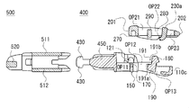
- 1 is a schematic exploded perspective view of a buckle according to a first embodiment of the present invention.
- FIG. 2 is a schematic exploded top view of the buckle according to the first embodiment of the present invention, in which the components are arranged vertically with the paper surface viewed from the front, the center lines of the components are on the same straight line, The left and right widths can be compared.
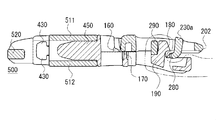
- It is a schematic exploded sectional view of the buckle concerning a 1st embodiment of the present invention, and shows a section before a male member and a female member connect, and shows each part of a male member separately.
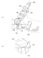
- FIG. 5 is a partially enlarged cross-sectional view of a buckle according to a third embodiment of the present invention
- FIGS. (A) to (c) show variations of the combination of the upper belt winding portion and the lower belt winding portion.
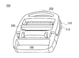
- FIG. 10 is a schematic exploded perspective view of a belt length adjuster according to a fourth embodiment of the present invention.
- each direction can be defined as follows. However, the following definitions are intended to assist understanding of the present invention and are not intended to limit the present invention.
- the left-right direction matches the pivot axis of the pivot member.
- the left-right direction may be called the axial direction.
- the vertical direction coincides with the stacking direction of the pivot member lying on the belt length adjuster body, or the stacking direction of the body member portion of the belt length adjuster and the pivot member portion lying on this part. .
- a direction perpendicular to the left-right direction and the up-down direction may be referred to as a length direction.
- the belt length adjuster is a buckle, it is possible to grasp the insertion direction of the female member relative to the male member and the removal direction of the male member from the female member.
- This insertion / removal direction is a direction orthogonal to the above-described left-right direction and up-down direction.
- the direction in which the pivot member pivots may be called the pivot direction. If the pivot range of the pivot member is not limited, the pivot direction has a circumferential trajectory. When the pivot range of the pivot member is limited, the pivot direction has a circular locus.
- FIG. 1 is a schematic perspective view of a buckle in which a belt length adjuster is integrated with a male member.
- FIG. 2 is a schematic exploded perspective view of the buckle.
- FIG. 3 is a schematic exploded top view of the buckle.
- the components are arranged vertically with the paper surface viewed from the front, the center lines of the components are on the same straight line, and the comparison of the left and right widths of the components is as follows. Is possible.
- FIG. 4 is a schematic exploded cross-sectional view of the buckle, showing a cross-section in a state before the male member and the female member are connected, and separately showing each part of the male member.
- FIG. 4 is a schematic exploded cross-sectional view of the buckle, showing a cross-section in a state before the male member and the female member are connected, and separately showing each part of the male member.
- FIG. 5 is a schematic cross-sectional view of the buckle, showing a cross-section in a state where the male member and the female member are connected, and illustrating the belt with a one-dot chain line.
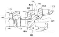
- FIG. 6 is a schematic partially enlarged cross-sectional view of the buckle, showing a state in which the pivot member is slightly inclined with respect to the main body.
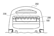
- FIG. 7 is a schematic partially enlarged top view of the male member of the buckle.
- FIG. 8 is a schematic diagram enlarging the range of the broken-line circle in FIG. 7 and shows that the unevenness between the belt pressing portions is alternately arranged.
- FIG. 9 is a schematic partially enlarged cross-sectional view of the buckle, showing a process in which the pivot member is lifted from the main body, and an enlarged range of a broken-line circle in FIG. .
- FIG. 10 is a schematic partial enlarged cross-sectional view of the buckle, showing a state in which the pivoting member stands on the main body, and an enlarged range of a broken-line circle in FIG. Show.
- the belt is not shown in FIGS.
- the buckle 600 includes a male member 400 and a female member 500
- the male member 400 includes a belt length adjuster 300 that can be understood from the following description.
- Including the belt length adjuster 300 in the male member 400 is merely an example.
- the belt length adjuster 300 may be included in the female member 500 instead of the male member 400, and may be provided in both the male member 400 and the female member 500.
- the belt length adjuster 300 may be provided separately from the male member 400 and the female member 500 in a detachable or non-detachable manner.
- the belt length adjuster 300 is provided not on the female member 500 but on the male member 400 to improve the operability of the buckle 600 as a whole.
- the male member 400 of the buckle 600 includes a main body 100 and a pivot member 200 that is pivotally supported by the main body 100 and can pivot on the main body 100.
- the main body 100 is provided with a lower belt winding portion 190
- the pivot member 200 is provided with an upper belt winding portion 290
- the upper belt winding portion 290 is They are arranged on the lower belt winding part 190 and are combined to form a belt winding part for the same belt. Note that the contact between the upper belt winding portion 290 and the lower belt winding portion 190 does not matter as will be described later.
- the female member 500 includes a body portion 510 and a belt winding portion 520.
- one end side of the belt is wound around the belt winding portion of the male member 400 (the belt winding portion formed by the upper belt winding portion 290 and the lower belt winding portion 190), and the other end side of the belt is It is wound around the belt winding portion 520 of the female member 500.
- one end side of the first belt is wound around the belt winding portion of the male member 400 (the belt winding portion formed by the upper belt winding portion 290 and the lower belt winding portion 190).
- One end side of the second belt different from the above is wound around the belt winding portion 520 of the female member 500.
- the belt 1 to 3 and the like is a woven fabric or knitted fabric having an arbitrary thickness and is typically a long body having a constant width. It does not matter.
- the belt may be called a tape, string, cord or the like.
- the material of the belt is arbitrary.
- the male member 400 may be called a plug, the female member 500 may be called a socket, and the pivot member 200 may be called a flap.
- the specific configurations of the main body 100 and the pivot member 200 of the male member 400 are arbitrary, and should not be limited to the specific shapes illustrated in the present application.
- Various forms of the specific structure of the female member 500 can be considered, and the disclosed form is merely an example.
- the male member 400 and the female member 500 are manufactured by molding a synthetic resin such as polyacetal resin or polyimide resin, but may be partially replaced with a metal member.
- a metal rod is insert-molded into the pivot member 200 corresponding to the pivot shaft, and the strength of the shaft is increased.
- a metal rod is embedded as a pivot shaft on the main body 100 side. It should be noted that the term “pivot” should be interpreted in a broad sense and includes forms with a narrower or wider pivot range.
- the main body 100 of the male member 400 includes a lower frame portion 110, a pair of left and right leg portions 410 that are connected to the lower frame portion 110 and extend in the insertion / removal direction, and a guide bar that extends in the insertion / removal direction between the left and right centers of the pair of left and right legs 410.
- 450 and a pair of left and right plates 460 connected to the base end of the guide rod 450 and extending in the insertion / removal direction.
- the lower frame part 110 is provided with at least one lower belt winding part 190 extending in the left-right direction.
- the lower belt winding part 190 is hung within the frame of the lower frame part 110.
- the lower frame portion 110 is provided with a pair of left and right shaft support portions 120, and a pair of left and right shaft portions 220 of the pivot member 200 described later are fitted to the pair of left and right shaft support portions 120.
- the lower frame part 110 includes at least a left bar part 110a, a right bar part 110b, and a bar-like end part 110c.
- the left bar portion 110a and the right bar portion 110b extend in the insertion / removal direction, and the rod-shaped end portion 110c extends in the left-right direction to connect the left bar portion 110a and the right bar portion 110b.
- the lower frame portion 110 has a C-shape or a U-shape due to the continuation of the left rod portion 110a, the right rod portion 110b, and the rod-shaped end portion 110c.
- rod part or a rod-shaped edge part is arbitrary, it is desirable that the outer peripheral surface and outer periphery which contact a human hand are curving.
- the lower frame part 110 is provided with a connecting structure 110d that connects the pair of left and right shaft support parts 120. If the shape of the lower frame part 110 including this connecting structure 110d is understood, the lower frame part 110 is grasped as a substantially rectangular closed frame. Further, the lower frame portion 110 has a pair of left and right shaft support portions 120 and a bent rod portion 110e to which the base end of the above-described leg portion 410, the base end of the guide rod 450, and the plate 460 are connected. Is provided. When the shape of the lower frame portion 110 including the bent rod portion 110e is understood, the lower frame portion 110 is grasped as a substantially rectangular closed frame body.
- the connecting structure 110d does not constitute the frame part of the lower frame part 110 but is built in the frame of the lower frame part 110.
- Intermediate connection structure The specific structure of the lower frame part 110 includes various forms such as an open frame facing an arbitrary direction, an arbitrarily shaped frame closed from the periphery, and a C-shape or U-shape facing an arbitrary direction. Conceivable. In any case, it should not be limited to the disclosed examples of the present application.
- the lower belt winding portion 190 continuously extends in a straight line in the left-right direction, and connects the left bar portion 110a and the right bar portion 110b.
- the lower belt winding part 190 is a bar part that is continuous to the left and right, but is not necessarily limited thereto.
- the lower belt winding part 190 is a discontinuous bar part that is divided at an arbitrary location, for example, the center of the left and right.
- the lower belt winding portion 190 is located between the rod-like end portion 110c and the connecting structure 110d, or between the rod-like end portion 110c and the bent rod portion 110e, and may be called an intermediate rod portion based on this relationship.
- openings OP11 and OP12 On both sides of the lower belt winding portion 190 in the insertion / removal direction, openings OP11 and OP12 having the same width that allow belt insertion are provided.
- An upper belt winding portion 290 of the pivoting member 200 is disposed on the lower belt winding portion 190, whereby the lower belt winding portion 190 and the upper belt winding portion 290 are combined to provide a belt for a common belt. Constructs a winding part. Thereby, the higher rigidity with respect to the tension
- An optional opening OP11 through which the belt can be inserted is provided between the lower belt winding portion 190 and the rod-shaped end portion 110c.
- a first opening OP12 through which the belt can be inserted is provided between the lower belt winding portion 190 and the connecting structure 110d.
- An optional opening OP13 that does not allow the belt to be inserted is provided between the coupling structure 110d and the bent rod portion 110e.
- the first opening OP12 and the optional opening OP11 are openings for belt insertion, and have the same left-right width W20. This lateral width W20 is slightly larger than the lateral width of the belt suitable for use with the buckle 600.
- the shaft support 120 includes a wall 125 that is thicker than each of the left bar 110a, the right bar 110b, and the connecting structure 110d.
- the pair of left and right walls 125 are provided with a pair of recesses 121 that are recessed from the inside in the axial direction to the outside.
- the inner side in the axial direction is a direction along the pivot axis and is a direction from the outside of the main body 100 toward the center.
- the axially outer side is a direction along the pivot axis and is a direction away from the center of the main body 100.
- the recess 121 is formed by a hole / notch extending from the lower surface of the wall portion 125 to a position between the upper surface of the connection structure 110 d and the upper surface of the wall portion 125.
- the space of the recess 121 communicates with the through hole 122 penetrating the connection structure 110d, and the recess 121 can be formed by the same mold part or mold core as the formation of the through hole 122 of the connection structure 110d.
- the pivoting member 200 is pivotally supported by the main body 100 and can pivot on the main body 100.
- the pivot member 200 can fall on the lower frame portion 110.
- the upper belt winding portion 290 of the pivot member 200 is placed on the lower belt winding portion 190 of the lower frame portion 110 as described above.
- the pivot member 200 includes a pair of left and right shaft portions 220.
- the shaft part 220 is engaged with the shaft support part 120, thereby ensuring the pivoting of the pivoting member 200 with respect to the main body 100.
- the shaft portion 220 is provided on the movable piece 221 that is slightly elastically deformable by the gap 222, and the pivot member with respect to the main body 100 after the main body 100 and the pivot member 200 are individually molded. 200 simple assemblies are allowed. It should be noted that the relationship of the shaft engagement between the pivot member 200 and the main body 100, that is, the relationship of unevenness may be reversed.
- the pivot member 200 has a proximal end 201 on the pivot axis side and a free end 202 on the opposite side
- the upper belt wrapping portion 290 has a proximal end 201.
- a second opening OP21 is provided on the base end 201 side of the upper belt winding portion 290
- a third opening OP22 is provided on the free end 202 side.
- the second opening OP21 and the third opening OP22 are belt insertion openings, and these have the left-right width W20.
- a grip portion 230 that is gripped when an operator of the buckle 600 grips the pivot member 200 is provided at the free end 202 of the pivot member 200.
- the grip portion 230 is provided with a third opening OP23, but this opening OP23 is merely a thinning and no belt is scheduled to be inserted.
- the straight rod portion 230a and the curved rod portion 230b are provided in such a manner as to sandwich the opening OP23.
- the opening for belt insertion is not necessarily limited to a closed opening, and may be an opening partially opened to an arbitrary degree.
- the pivot member 200 has the above-mentioned pair of left and right rod portions 210a and 210b, and has a base portion 218 on the base end 201 side and a grip portion 230 on the free end 202 side for connecting them, thereby forming a frame shape. Composed.
- the pivot member 200 includes an upper frame portion 210, and the upper frame portion 210 includes a pair of left and right rod portions 210 a and 210 b, a base portion 218, and a grip portion 230.
- An upper belt wrapping portion 290 is hung within the frame of the upper frame portion 210.
- the upper belt wrapping portion 290 is disposed between the base portion 218 and the grip portion 230, and thus may be referred to as an intermediate rod portion.
- the upper belt winding part 290 is preferably a continuous or non-continuous bar part.
- the main body 100 of the male member 400 is provided with the male structure of the male member of a normal buckle as described above.
- the main body 100 of the male member 400 has a pair of left and right leg portions 410, guide bars 450, and left and right.
- a pair of plates 460 are provided.
- the pair of left and right legs 410, the guide bar 450, and the pair of left and right plates 460 are connected to the bent bar 110e, but other modes are also conceivable.
- the pair of left and right leg portions 410 have shapes that are close to each other from the proximal end toward the distal end side, can be approached to each other according to an operation by the operator, and can be elastically restored to the original shape after releasing the external force.
- the illustrated leg portion 410 is provided with an operation portion 420 having a large vertical thickness that is pushed inward by an operator's finger of the buckle 600. When the external force applied to the operation unit 420 is released, the leg portion 410 elastically returns to the original posture.
- the leg portion 410 is provided with an engaging protrusion 430 projecting up and down at the tip portion.
- the engaging protrusion 430 can be engaged with an engaged portion 530 provided on the female member 500, and the male member is engaged by the engagement of the engaging protrusion 430 of the leg portion 410 and the engaged portion 530 of the female member 500. 400 and the female member 500 are secured.
- the leg portion 410 is provided with a spring portion 440 extending in a J shape so as to connect the operation portion 420 and the engaging protrusion 430 and to connect the engaging protrusion 430 and the bending rod portion 110e.
- the spring part 440 has a smaller vertical thickness than the operation part 420 and the engaging protrusion 430, and its inner part (the part connecting the engaging protrusion 430 and the bending rod part 110e) has its outer part (bending with the engaging protrusion 430). It is configured to be narrower in the left-right width than the portion connecting the rod portion 110e. Due to the spring property of the spring portion 440, the elastic return to the original position of the leg portion 410 is ensured.
- the guide rod 450 is provided to ensure stable insertion of the male member 400 into the female member 500 or stable extraction of the male member 400 from the female member 500, and a pair of left and right with the left and right center of the bent rod portion 110e as a base point.
- the middle of the leg portion 410 extends to be separated from the lower frame portion 110.
- the plate 460 is provided to define the insertion limit of the male member 400 with respect to the female member 500.
- the body portion 510 of the female member 500 has a hollow structure in which an upper plate 511 and a lower plate 512 are arranged to face each other, and has an inlet 515 and an outlet 516. As shown in FIG. 2, slits SL ⁇ b> 510 that allow insertion of the leg portions 410 are provided on the left and right side walls of the body portion 510.
- the body 510 is provided with an engaged portion 530 that guides the engaging protrusion 430 from the entrance 515 to the exit 516 and engages the engaging projection 430.
- the non-restricted exemplary engaged portion 530 is a vertically symmetrical step structure provided on the inner surface of the upper plate 511 and the inner surface of the lower plate 512.
- the engaging protrusion 430 guided by the step structure reaches the outlet 516 of the body 510, and due to the elastic recovery of the leg 410, the side surface of the engaging protrusion 430 on the side of the bent rod 110e is the end surface 530a of the step structure.
- the body portion 510 is provided with a guide portion 550 that guides the movement of the guide rod 450.
- the guide portion 550 is configured by a pair of left and right guide walls that are spaced apart by the left and right widths of the guide rod 450.
- the plate 460 collides with the end of the guide wall on the entrance 515 side, and the stop position of the male member 400 is defined.
- the belt winding portion 520 is a rod portion that continuously extends linearly in the left-right direction, and defines an opening OP50 for belt insertion between the belt winding portion 520 and the body portion 510.
- the belt winding part 520 is divided
- the specific aspect of the latching of the male member 400 and the female member 500 of the buckle 600 is arbitrary.
- the positions of the engaging part and the engaged part may be changed.
- the lower belt winding portion 190 is provided with a step-shaped accommodation portion 191, and the lower belt winding portion 190 is configured to have a substantially L-shaped cross section.
- the step-shaped accommodating portion 191 is provided with a step bottom surface 191a and a step side surface 191b as step surfaces.
- the step bottom surface 191a is a flat surface extending in the left-right direction.
- the step side surface 191b is a flat surface extending in the left-right direction, and rises upward from the step bottom surface 191a.
- the lower belt winding portion 190 is provided with a step-shaped accommodation portion 191, thereby securing a space for arranging the upper belt winding portion 290 in the lower belt winding portion 190.
- the upper belt winding portion 290 is disposed on the step bottom surface 191a of the step-shaped accommodating portion 191 and next to the step side surface 191b, in other words, the front side in the insertion / removal direction. Placed in.
- the belt is drawn in an arbitrary direction with the belt wound around the belt winding portion constituted by the cooperation of the lower belt winding portion 190 and the upper belt winding portion 290, the upper belt winding portion 290 It contacts the step bottom surface 191a or the step side surface 191b of the belt winding portion 190, and these integrally act as a belt winding portion and have the combined rigidity.
- the upper belt winding portion 290 contacts the step bottom surface 191a or the step side surface 191b of the step-shaped accommodating portion 191 in a state where the belt is not wound. That is, the upper belt winding portion 290 may be in non-contact with either the step bottom surface 191a or the step side surface 191b of the step-shaped accommodating portion 191 in a state where the belt is not wound.
- the upper belt winding portion 290 and the lower belt winding portion 190 are combined in the vertical direction and the insertion / removal direction (length direction), and various tensions of the wound belt Can be countered.
- the lower belt winding portion 190 is stationary, but the upper belt winding portion 290 is displaced rearward in the insertion / removal direction.
- the lower belt winding portion 190 functions as a barrier for the upper belt winding portion 290.
- the lower belt winding portion 190 functions as a barrier for the upper belt winding portion 290. This point is considered to contribute to the high rigidity of the winding part constituted by the combination of the upper belt winding part 290 and the lower belt winding part 190. The same can be considered when the upper belt winding portion 290 is in a stationary state and the lower belt winding portion 190 is displaced.
- the step side surface 191b extends upward from the step bottom surface 191a, the step side surface 191b is inclined away from the pivot shaft of the pivot member 200, whereby the lower belt winding portion 190 and the upper belt winding portion. The interference of the part 290 is suppressed.
- a second belt pressing portion 180 is provided on the upper or upper end portion of the lower belt winding portion 190, and the second belt pressing portion 180 is provided in a direction opposite to the pivot axis of the pivot member 200.
- a first belt pressing portion 280 is provided at a lower portion or a lower end portion of the straight rod portion 230a of the gripping portion 230, and the first belt pressing portion 280 protrudes toward and faces the pivot shaft side of the pivot member 200. Is provided. As shown in FIG. 5, when the pivot member 200 falls on the lower frame part 110, the second belt pressing part 180 and the first belt pressing part 280 are provided in a manner facing in opposite directions. The belt indicated by the alternate long and short dash line in FIG.
- the pivot member 200 falls on the lower frame 110. When it does, it is suitably inserted between the 1st belt press part 280 and the 2nd belt press part 180, and is compressed.
- the second belt pressing portion 180 is configured as an inclined portion, and the inclined portion slowly increases in thickness from the front side in the insertion / removal direction to the rear side in the insertion / removal direction as it extends from top to bottom. Further, an inclined surface 180f that is separated from the pivot axis of the pivot member 200 as it extends from top to bottom is provided.
- the first belt pressing portion 280 is configured as a claw portion and protrudes from the lower end portion of the straight bar portion 230a of the grip portion 230 toward the pivot shaft side of the pivot member 200. As can be understood from FIG.
- the belt is pressed between the first belt pressing portion 280 and the second belt pressing portion 180.
- the lock described here is not a direct lock between the first belt pressing portion 280 and the second belt pressing portion 180 but a lock with a flexible belt.
- the first belt pressing portion 280 has a first uneven structure 280a for pressing the belt
- the second belt pressing portion 180 has a second uneven structure 180a for pressing the belt.
- the first uneven structure 280a and the second uneven structure 180a are configured such that the unevenness is alternately arranged. That is, the convex part of the 2nd uneven structure 180a is positioned between the adjacent convex parts of the 1st uneven structure 280a, and this aspect continues in the left-right direction. Interference between the first uneven structure 280a and the second uneven structure 180a during the pivoting process of the pivot member 200 is avoided or suppressed.
- the belt winding portion is divided into an upper belt winding portion 290 and a lower belt winding portion 190, and the belt is sandwiched between the first belt pressing portion 280 and the second belt pressing portion 180. Is introduced. In view of this point, it is preferable to ensure further stabilization of the operation of the pivot member 200.
- a contact portion 170 is provided at the left and right center of the connection structure 110d that connects the pair of left and right shaft support portions 120 of the lower frame portion 110, and the contact portion is provided on the base portion 218 of the pivot member 200. A contacted portion 270 to be contacted by 170 is provided.
- the contact part 170 contacts the contacted part 270 in the whole or part of the process in which the pivot member 200 pivots, and the stable pivoting is ensured. Further stabilization of the pivot of the pivot member 200 based on the engagement between the shaft support 120 and the shaft 220 can be achieved.
- the contacted portion 270 gets over the top of the contact portion 170.
- the flat surface 270 a of the contacted portion 270 is placed on the top of the contact portion 170 and becomes a fulcrum for supporting the pivot member 200.
- a pair of left and right pedestal portions 160 are provided on the left and right sides of the opening OP13 of the connection structure 110d, and the base 218 of the pivot member 200 is placed on the pedestal portion 160.
- the pedestal portion 160 is an inclined portion whose thickness decreases from the front side to the rear side in the insertion / removal direction, in other words, in the direction closer to the pivot shaft.
- the upper surface of the pedestal unit 160 is inclined flat.
- the method of hanging / passing the belt is arbitrary, but in this example, the belt is passed through the first opening OP12, the second opening OP21, and the third opening OP22 in this order or vice versa. Although not shown, a belt may be passed through the opening OP11.
- the pivot member 200 locked on the lower frame portion 110 can be raised by lifting the belt instead of operating the pivot member 200 itself. Therefore, even when the pivot member 200 is provided and the lock is performed by the cooperation of the first belt pressing portion 280 and the second belt pressing portion 180 sandwiching the belt, the trouble of adjusting the belt length is complicated. Don't be.
- the pivot member 200 not the belt itself, may be held and raised, and the length of the belt may be adjusted. Giving a width to the usage mode of the belt length adjuster is also preferable from the viewpoint of improving the commercial value.
- FIG. 11 is a partially enlarged sectional view of the buckle.
- FIG. 11 (a) shows a state where the pivoting member is simply positioned at a predetermined angle
- FIG. 11 (b) shows the state of FIG. It is the schematic which expanded the range of the broken-line circle.
- a recess is provided in the contact portion or the contacted portion in order to stop / temporarily stop the pivot member 200 at a predetermined angle. Even in such a case, the same effect as the first embodiment can be obtained.
- the contacted portion 270 is provided with a recess 275 for defining a stop angle.
- the pivot member 200 can temporarily stop in the posture shown in FIG.
- the top of the contact portion 170 is rounded, and the force required for engagement / disengagement with the recess 275 is very small.
- a concave portion may be provided in the contact portion 170 to achieve the same effect.
- FIG. 12 is a partial enlarged cross-sectional view of the buckle, and FIGS. 12A to 12C show variations of combinations of the upper belt winding portion and the lower belt winding portion. According to this embodiment, it is shown that the combination aspect of the upper belt winding part 290 and the lower belt winding part 190 is various.
- the flat lower surface of the upper belt winding portion 290 is disposed on the flat upper surface of the lower belt winding portion 190, and both are in surface contact with each other over a wide range.
- the contact resistance between the two increases due to the surface contact in a wide range, and when the upper belt winding portion 290 is displaced with respect to the lower belt winding portion 190 or vice versa, a larger force is required. become. That is, relative displacement of the lower belt winding portion 190 and the upper belt winding portion 290 is suitably suppressed according to the force received from the belt.
- the width of the upper belt winding portion 290 in the insertion / removal direction (length direction) can be made larger than the structure of the first embodiment, and the upper belt winding portion 290 can be formed. The strength of is improved.
- the flat inclined surface of the upper belt winding portion 290 is disposed on the flat inclined surface of the lower belt winding portion 190.
- the pivot member 200 falls on the lower frame portion 110 of the male member 400, the upper belt winding portion 290 and the lower belt winding portion 190 are guided by the mutually inclined surfaces, and the operability of the pivot member 200 is improved. Will improve.
- the lower belt winding portion 190 is provided with a step-shaped accommodation portion 191 on the side far from the pivot axis of the pivot member 200, in other words, on the rear side in the insertion / removal direction.
- An upper belt winding portion 290 is disposed on the step surface of the accommodating portion 191. 12C, the wall portion of the lower belt winding portion 190 is disposed between the pivot shaft of the pivot member 200 and the upper belt winding portion 290. Even in this case, the same effect as the first embodiment can be obtained.
- FIG. 13 is a schematic perspective view of a belt length adjuster.
- FIG. 14 is a schematic exploded perspective view of the belt length adjuster.
- the belt length adjuster is not incorporated into the buckle. Even in such a case, the same effects as those described in the above embodiment can be obtained.
- the main body 100 is provided with a belt winding portion 199. Similar to the above-described embodiment, the upper belt winding portion 290 of the pivot member 200 and the lower belt winding portion 190 of the main body 100 constitute a belt winding portion.
- the number of belts wound around the same belt winding portion is arbitrary, and may be two or more.
- a plurality of upper belt winding portions may be provided, a plurality of lower belt winding portions may be provided, and these may be combined individually to provide a plurality of winding portions for the same belt.
- Reference signs included in the claims are for reference only and should not be referenced for the purpose of limiting the scope of the claims.
Landscapes
- Buckles (AREA)
Abstract
ベルト長さ調整具(300)は、本体(100)、及び本体(100)により枢支されて本体(100)上で枢動可能である枢動部材(200)を備える。本体(100)が、少なくとも一つの下部ベルト巻付部(190)を含み、枢動部材(200)が、少なくとも一つの上部ベルト巻付部(290)を含み、少なくとも一つの下部ベルト巻付部(190)と少なくとも一つの上部ベルト巻付部(290)が、枢動部材(200)が本体(100)上に倒伏する時に組み合わされて同一のベルト用の巻付部を構成する。
Description
本開示は、ベルト長さ調整具に関し、またこのベルト長さ調整具を含むバックルに関する。
特許文献1には、帯状体の長さ調節が容易な分割型の接続具が開示されている。同文献の図2に開示のように、雄部材3には固定部材4と可動部材21が設けられる。同文献の図3に開示のように、可動部材21の中央材23には帯状体1が巻き付けられる。
特許文献2には、プラグ10にフラップ30が回動自在に支持された構成が開示されている。同文献の図7に開示のように、棒状部分39にはベルト3が巻き付けられる。
本開示の一側面は、本体に対して枢動部材が枢動可能に設けられるベルト長さ調整具において、ベルトが巻き付けられるベルト巻付部の強度向上を図ることにある。
本発明の一態様に係るベルト長さ調整具は、本体(100)、及び前記本体(100)により枢支されて前記本体(100)上で枢動可能である枢動部材(200)を備えるベルト長さ調整具(300)であって、前記本体(100)が、少なくとも一つの下部ベルト巻付部(190)を含み、前記枢動部材(200)が、少なくとも一つの上部ベルト巻付部(290)を含み、前記少なくとも一つの下部ベルト巻付部(190)と前記少なくとも一つの上部ベルト巻付部(290)が、前記枢動部材(200)が前記本体(100)上に倒伏する時に組み合わされて同一のベルト用の巻付部を構成する。
前記枢動部材(200)が、前記少なくとも一つの上部ベルト巻付部(290)が枠内に架けられた上部枠部(210)を含み、前記本体(100)が、前記少なくとも一つの下部ベルト巻付部(190)が枠内に架けられた下部枠部(110)を含み、前記枢動部材(200)の前記上部枠部(210)が前記本体(100)の前記下部枠部(110)上に倒伏可能である、と良い。
前記下部ベルト巻付部(190)には段差状収容部(191)が設けられ、当該段差状収容部(191)の段差面上に前記上部ベルト巻付部(290)が配置可能である、と良い。
前記枢動部材(200)がその枢動軸側の基端(201)、及び当該基端(201)とは反対側の自由端(202)を含み、前記少なくとも一つの上部ベルト巻付部(290)よりも前記自由端(202)側に第1ベルト押さえ部(280)が設けられ、前記少なくとも一つの下部ベルト巻付部(190)には、前記枢動部材(200)が前記本体(100)上に倒伏する時に前記第1ベルト押さえ部(280)と共にベルトを挟み込む第2ベルト押さえ部(180)が設けられる、と良い。
前記第1ベルト押さえ部(280)及び前記第2ベルト押さえ部(180)には、凸凹が互い違いの凸凹構造(180a、280a)が設けられる、と良い。
前記枢動部材(200)が前記本体(100)上に倒伏する時に前記第1ベルト押さえ部(280)の少なくとも一部が前記第2ベルト押さえ部(180)よりも下方に配される、と良い。
本発明の別態様に係るバックルは、挿脱可能な雄部材(400)及び雌部材(500)を備えるバックル(600)であって、上述に記載のベルト長さ調整具(300)が前記雄部材(400)及び前記雌部材(500)の少なくとも一方に設けられる。
本発明の一側面によれば、ベルトが巻き付けられるベルト巻付部の強度向上を図ることができる。
以下、図面を参照しつつ、本発明の実施の形態について説明する。各実施形態は、個々に独立したものではなく、過剰説明をするまでもなく、当業者をすれば、適宜、組み合わせることが可能であり、この組み合わせによる相乗効果も把握可能である。実施形態間の重複説明は、原則的に省略する。参照図面は、発明説明を主目的とするものであり、適宜、簡略化されている。
実施形態の説明に関して、次のように各方向を定義できる。但し、次の定義は、本願発明の理解を助けるためのものであり、本願発明を限定するためのものではない。左右方向は、枢動部材の枢動軸に合致する。左右方向を軸方向と呼んでも構わない。上下方向は、ベルト長さ調整具の本体上に倒伏した枢動部材の積層方向、若しくはベルト長さ調整具の本体の部分とこの部分上に倒伏した枢動部材の部分の積層方向に合致する。左右方向及び上下方向に対して直交する方向を長さ方向と呼んでも良い。ベルト長さ調整具がバックルの場合、雄部材に対する雌部材の挿入方向、雌部材からの雄部材の脱着方向を把握できる。この挿脱方向は、上述の左右方向及び上下方向に直交する方向である。枢動部材が枢動する方向を枢動方向と呼んでも構わない。枢動部材の枢動範囲に制限がなければ枢動方向が円周の軌跡を持つ。枢動部材の枢動範囲に制限がある場合、枢動方向が円弧の軌跡を持つ。
<第1実施形態>
図1乃至図10を参照して第1実施形態について説明する。図1は、ベルト長さ調整具が雄部材に一体化したバックルの概略斜視図である。図2は、バックルの概略分解斜視図である。図3は、バックルの概略分解上面図であり、ここでは紙面を正面視して構成部品を縦に並べ、各構成部品の中心線が同一直線上にあり、各構成部品の左右幅の比較が可能である。
図4は、バックルの概略分解断面図であり、雄部材と雌部材が連結する前の状態の断面を示し、また雄部材の各部品を分離して示す。図5は、バックルの概略断面図であり、雄部材と雌部材が連結した状態の断面を示し、また一点鎖線でベルトを図示する。図6は、バックルの概略的な部分拡大断面図であり、枢動部材が本体に対して僅かに傾いている状態を示す。図7は、バックルの雄部材の概略的な部分拡大上面図である。図8は、図7の破線円の範囲を拡大した概略図であり、ベルト押さえ部同士の凸凹が互い違いに配されることを示す。図9は、バックルの概略的な部分拡大断面図であり、枢動部材が本体から持ち上げられる過程を示し、同図(a)の破線円の範囲を拡大したものを同図(b)に示す。図10は、バックルの概略的な部分拡大断面図であり、枢動部材が本体上で起立した状態を示し、同図(a)の破線円の範囲を拡大したものを同図(b)に示す。なお、バックルの構成を詳細に図示するため、図1乃至図3では、ベルトの図示を省略している。
図1乃至図10を参照して第1実施形態について説明する。図1は、ベルト長さ調整具が雄部材に一体化したバックルの概略斜視図である。図2は、バックルの概略分解斜視図である。図3は、バックルの概略分解上面図であり、ここでは紙面を正面視して構成部品を縦に並べ、各構成部品の中心線が同一直線上にあり、各構成部品の左右幅の比較が可能である。
図4は、バックルの概略分解断面図であり、雄部材と雌部材が連結する前の状態の断面を示し、また雄部材の各部品を分離して示す。図5は、バックルの概略断面図であり、雄部材と雌部材が連結した状態の断面を示し、また一点鎖線でベルトを図示する。図6は、バックルの概略的な部分拡大断面図であり、枢動部材が本体に対して僅かに傾いている状態を示す。図7は、バックルの雄部材の概略的な部分拡大上面図である。図8は、図7の破線円の範囲を拡大した概略図であり、ベルト押さえ部同士の凸凹が互い違いに配されることを示す。図9は、バックルの概略的な部分拡大断面図であり、枢動部材が本体から持ち上げられる過程を示し、同図(a)の破線円の範囲を拡大したものを同図(b)に示す。図10は、バックルの概略的な部分拡大断面図であり、枢動部材が本体上で起立した状態を示し、同図(a)の破線円の範囲を拡大したものを同図(b)に示す。なお、バックルの構成を詳細に図示するため、図1乃至図3では、ベルトの図示を省略している。
図1乃至3に示すように、バックル600は、雄部材400と雌部材500を含み、雄部材400には後述の説明から理解されるベルト長さ調整具300が含まれる。雄部材400にベルト長さ調整具300を含めることは単なる一例である。雄部材400に代替して雌部材500にベルト長さ調整具300を含めても良く、更には、雄部材400と雌部材500の両方に設けても良い。雄部材400や雌部材500とは別体として着脱可能又は着脱不能な態様でベルト長さ調整具300を設けても良い。
バックル600の使用者は、雄部材400を把持及び操作し、雌部材500に対して雄部材400を挿脱させることが見込まれる。例示の本形態では、この点に鑑み、ベルト長さ調整具300を雌部材500ではなく雄部材400に設け、バックル600全体の操作性を向上させている。
バックル600の雄部材400は、本体100と当該本体100により枢支されて本体100上で枢動可能である枢動部材200を含む。本体100には下部ベルト巻付部190が設けられ、枢動部材200には上部ベルト巻付部290が設けられ、枢動部材200が本体100上に倒伏する時、上部ベルト巻付部290が下部ベルト巻付部190上に配置され、これらが組み合わされて同一のベルト用のベルト巻付部を構成する。なお、後述のように上部ベルト巻付部290と下部ベルト巻付部190の接触の如何は問わない。
雌部材500は、胴部510とベルト巻付部520を含む。非限定の一形態では、ベルトの一端側が雄部材400のベルト巻付部(上部ベルト巻付部290と下部ベルト巻付部190が構成するベルト巻付部)に巻き付けられ、ベルトの他端側が雌部材500のベルト巻付部520に巻き付けられる。非限定の別形態では、第1ベルトの一端側が雄部材400のベルト巻付部(上部ベルト巻付部290と下部ベルト巻付部190が構成するベルト巻付部)に巻き付けられ、第1ベルトとは異なる第2ベルトの一端側が雌部材500のベルト巻付部520に巻き付けられる。図1乃至図3等では不図示のベルトは、任意の程度の肉厚の柔軟性がある織物若しくは編物類であり、典型的には一定幅の長尺体であるが、これ以外の形態にあっても構わない。ベルトをテープ、紐、コード等と呼んでも構わない。ベルトの材質は任意である。
雄部材400をプラグと呼び、雌部材500をソケットと呼び、枢動部材200をフラップと呼んでも構わない。雄部材400の本体100及び枢動部材200の具体的構成は任意であり、本願に図示の具体的な形状に限られるべきではない。雌部材500の具体的構造は、様々な形態が考えられ、開示の形態は一例であるに過ぎない。雄部材400や雌部材500は、ポリアセタール樹脂、ポリイミド樹脂などの合成樹脂の金型成形により製造されるが、部分的に金属部材で置換しても良い。例えば、枢動軸に対応して金属棒が枢動部材200にインサート成形され、その軸の強度が高められる。若しくは、本体100側に金属棒が枢動軸として埋め込まれる。なお、「枢動」との用語は広義に解釈されるべきであり、枢動範囲がより狭い若しくはより広い形態も包含する。
雄部材400の本体100は、下部枠部110、下部枠部110に連結して挿脱方向に延びる左右一対の脚部410、左右一対の脚部410の左右中央を挿脱方向に延びるガイド棒450、及びガイド棒450の基端に連結して挿脱方向に延びる左右一対のプレート460を含む。下部枠部110には、左右方向に延びる少なくとも一つの下部ベルト巻付部190が設けられる。下部ベルト巻付部190は、下部枠部110の枠内に架けられる。更に、下部枠部110には、左右一対の軸支部120が設けられ、この左右一対の軸支部120に対して後述の枢動部材200の左右一対の軸部220が嵌め合わされる。
本実施形態に開示の非限定の一形態では、図3に端的に示すように、下部枠部110は、少なくとも左側棒部110a、右側棒部110b、及び棒状端部110cを含む。左側棒部110a及び右側棒部110bが挿脱方向に沿って延び、棒状端部110cが左右方向に延びて左側棒部110a及び右側棒部110bを連結する。下部枠部110は、左側棒部110a、右側棒部110b、及び棒状端部110cの連続によりC字状若しくはU字状の形状を呈する。なお、棒部や棒状端部の断面形状は任意であるが、人の手に接触する外周面や外周縁が湾曲していることが望ましい。
下部枠部110には、左右一対の軸支部120の間を連結する連結構造110dが設けられる。この連結構造110dを含めて下部枠部110の形状を理解すると、下部枠部110は、略矩形状の閉じた枠体と把握される。更に、下部枠部110には、左右一対の軸支部120の間を連結すると共に、上述の脚部410の基端、ガイド棒450の基端、更にはプレート460が連結する屈曲棒部110eが設けられている。この屈曲棒部110eを含めて下部枠部110の形状を理解すると、下部枠部110は、略矩形状の閉じた枠体と把握される。
連結構造110dと屈曲棒部110eの両方が下部枠部110に含まれると把握する場合、連結構造110dは、下部枠部110の枠部分を構成せず、下部枠部110の枠内に架けられた中間連結構造になる。下部枠部110の具体的構造は、任意の方向に向いた開いた枠、周囲から閉じられた任意の形状の枠、任意の方向に向いたC字状やU字状等の様々な形態が考えられる。いずれにしても本願の開示例に限定されるべきではない。
下部ベルト巻付部190は、左右方向に直線状に連続して延び、左側棒部110aと右側棒部110bを連結する。下部ベルト巻付部190は、左右に連続した棒部であるが、必ずしもこの限りではなく、別形態では、任意の箇所、例えば左右中央で分断された非連続の棒部である。下部ベルト巻付部190は、棒状端部110cと連結構造110d、若しくは棒状端部110cと屈曲棒部110eの間に位置し、この関係から中間棒部と呼んでも良い。下部ベルト巻付部190の挿脱方向の両隣には、ベルト挿通が可能な同幅の開口OP11、OP12が設けられる。
下部ベルト巻付部190上には、枢動部材200の上部ベルト巻付部290が配置され、これにより、下部ベルト巻付部190と上部ベルト巻付部290が組み合わされて共通のベルトに対するベルト巻付部を構成する。これにより、ベルトの引っ張り等に対するより高い剛性をベルト巻付部に付与することができる。本体100や枢動部材200の一方のみで十分な剛性のベルト巻付部を構成することは容易ではない。上述の構成によれば、この問題に対する解決方法が提供される。
特段の限定の意図を有せずに本実施形態に開示の一形態についてより詳細に説明する。下部ベルト巻付部190と棒状端部110cの間にはベルトの挿通が可能なオプションの開口OP11が設けられる。下部ベルト巻付部190と連結構造110dの間にはベルトの挿通が可能な第1開口OP12が設けられる。連結構造110dと屈曲棒部110eの間にはベルトの挿通を許容しないオプションの開口OP13が設けられる。第1開口OP12やオプションの開口OP11は、ベルト挿通用の開口であり、同じ左右幅W20を有する。この左右幅W20はバックル600の使用に適したベルトの左右幅よりも僅かに大きい。
左右一対の軸支部120の具体的構造について、特段の限定の意図を有せずにより詳細に説明する。本実施形態に開示の一形態では、軸支部120は、左側棒部110a、右側棒部110b、連結構造110dの各肉厚よりも肉厚が厚い壁部125を含む。左右一対の壁部125には軸方向内側から外側へ凹む一対の凹部121が設けられる。軸方向内側は、枢動軸に沿う方向であり、本体100の外から中心に向かう方向である。軸方向外側は、枢動軸に沿う方向であり、本体100の中心から外へ離れる方向である。この凹部121は、壁部125の下面から連結構造110dの上面と壁部125の上面の間の位置まで延びる穴/切り欠きにより形成される。凹部121の空間が、連結構造110dを貫通する貫通穴122に空間連通し、連結構造110dの貫通穴の122の形成と同じ金型部分若しくは金型コアで凹部121を形成できる。
枢動部材200は、本体100により枢支され、本体100上で枢動可能である。枢動部材200は、下部枠部110上に倒伏することができ、この時、上述のように、枢動部材200の上部ベルト巻付部290が下部枠部110の下部ベルト巻付部190上に配置されて一緒に同一のベルト用のベルト巻付部を構成する。枢動部材200は、左右一対の軸部220を備える。軸部220が軸支部120に係合され、これにより、本体100に対する枢動部材200の枢動が確保される。本実施形態に開示の一例では、軸部220が、隙間222により僅かに弾性変形可能な可動片221に設けられ、本体100と枢動部材200を個別に成形した後の本体100に対する枢動部材200の簡単な組み立てが許容される。なお、枢動部材200と本体100の軸係合の関係、つまり凸凹の関係を反転させても構わない。
本実施形態に開示の一形態では、枢動部材200が、枢動軸側の基端201と、これとは反対側の自由端202を有し、上部ベルト巻付部290が基端201と自由端202の間に設けられる。上部ベルト巻付部290の基端201側には第2開口OP21が設けられ、その自由端202側には第3開口OP22が設けられる。第2開口OP21や第3開口OP22は、ベルト挿通用の開口であり、これらは同じく左右幅W20を有する。
バックル600の操作者が枢動部材200を把持する際に把持される把持部230が枢動部材200の自由端202に設けられる。把持部230には第3開口OP23が設けられるが、この開口OP23は、単なる肉抜きであり、ベルトの挿通が予定されていない。開口OP23を挟む態様で直線棒部230aと湾曲棒部230bが設けられる。なお、ベルト挿通用の開口は、必ずしも閉じた開口に限らず、任意の程度で部分的に解放した開口であっても良い。
枢動部材200は、上述の左右一対の棒部210a、210bを有し、またこれらを連結する基端201側の基部218と自由端202側の把持部230を有し、これにより枠状に構成される。換言すれば、枢動部材200が上部枠部210を含み、この上部枠部210が、左右一対の棒部210a、210b、基部218、及び把持部230を含む。上部枠部210の枠内には上部ベルト巻付部290が架けられる。上部ベルト巻付部290は、基部218と把持部230の間に配置され、従って、これを中間棒部と呼んでも良い。上部ベルト巻付部290は、好適には連続又は非連続の棒部である。
雄部材400の本体100には、上述のように通常のバックルの雄部材が具備する雄構造が設けられ、雄部材400の本体100には、左右一対の脚部410、ガイド棒450、及び左右一対のプレート460が設けられる。本実施形態に開示の一例では、左右一対の脚部410、ガイド棒450、及び左右一対のプレート460が屈曲棒部110eに連結するが、これ以外の態様も考えられる。
左右一対の脚部410は、基端から先端側に向かい互いに近接するような形状を持ち、操作者による操作に応じて互いに接近可能であり、またその外力の解放後に元形状に弾性復帰できる。例示の脚部410には、バックル600の操作者の指により内側に押される上下厚が大きい操作部420が設けられる。操作部420に付与される外力の解除により脚部410は元姿勢に弾性復帰する。脚部410には、その先端部に上下に突出した係合突起430が設けられる。この係合突起430は、雌部材500に設けられた被係合部530に係合可能であり、脚部410の係合突起430と雌部材500の被係合部530の係合により雄部材400と雌部材500の係止が確保される。
更に、脚部410には、操作部420と係合突起430を連結し、係合突起430と屈曲棒部110eを連結するようにJ字状に延びるバネ部440が設けられる。バネ部440は、操作部420や係合突起430よりも上下厚が小さく、その内側部(係合突起430と屈曲棒部110eとを連結する部分)がその外側部(係合突起430と屈曲棒部110eとを連結する部分)よりも左右幅狭に構成される。バネ部440のバネ性により、脚部410の元位置への弾性復帰が確保される。
ガイド棒450は、雌部材500への雄部材400の安定挿入、若しくは雌部材500からの雄部材400の安定抜き出しを確保するために設けられ、屈曲棒部110eの左右中央を基点として左右一対の脚部410の中間を下部枠部110から離間するべく延びる。プレート460は、雌部材500に対する雄部材400の挿入限界を規定するべく設けられる。
雌部材500の胴部510は、上板511と下板512が対向配置した中空構造であり、入り口515と出口516を有する。図2に示すように、胴部510の左右側壁には、脚部410の挿入を許容するスリットSL510が設けられている。胴部510には入り口515から出口516まで係合突起430をガイドし、これが係合する被係合部530が設けられる。非限定の例示の被係合部530は、上板511の内面と下板512の内面に設けられた上下対称の段差構造である。この段差構造にガイドされた係合突起430は、胴部510の出口516に至り、脚部410の弾性復帰に起因し、係合突起430の屈曲棒部110e側の側面が段差構造の端面530aに係合・合致し、これにより、雄部材400が雌部材500により係止されて両者が連結する。胴部510にはガイド棒450の移動を案内するガイド部550が設けられる。例えば、ガイド部550は、ガイド棒450の左右幅分の間隔をあけて配された左右一対のガイド壁により構成される。このガイド壁の入り口515側の端部にプレート460が衝突し、雄部材400の停止位置が規定される。ベルト巻付部520は、左右方向に直線状に連続して延びる棒部であり、胴部510との間にベルト挿通用の開口OP50を規定する。別形態においては、ベルト巻付部520は、任意の箇所で分断され、非連続に構成される。
なお、バックル600の雄部材400と雌部材500の係止の具体的態様は任意である。係合部と被係合部の位置を変えても構わない。
図4乃至図6に示すように、下部ベルト巻付部190には段差状収容部191が設けられ、下部ベルト巻付部190が断面略L字状に構成される。段差状収容部191は、段差面として段差底面191aと段差側面191bが設けられる。段差底面191aは、左右方向に延びる平坦面である。段差側面191bは、左右方向に延びる平坦面であり、段差底面191aから上方に立ち上がる。下部ベルト巻付部190に段差状収容部191が設けられ、これにより下部ベルト巻付部190に上部ベルト巻付部290を配置する空間が確保される。もちろん、段差状収容部191を設けることは好ましいが必須ではなくオプションである。
枢動部材200が下部枠部110上に倒伏する時、上部ベルト巻付部290が、段差状収容部191の段差底面191aに配置され、段差側面191bの横隣、換言すれば挿脱方向前側に配置される。下部ベルト巻付部190と上部ベルト巻付部290の協同で構成されるベルト巻付部にベルトが巻き付けられた状態でベルトが任意の方向に引かれた時、上部ベルト巻付部290が下部ベルト巻付部190の段差底面191a又は段差側面191bに接触し、これらが一体的にベルト巻付部として作用し、合算された剛性を持つ。この説明から理解できるように、ベルトが巻き付けられていない状態で上部ベルト巻付部290が段差状収容部191の段差底面191aや段差側面191bに接触するか否かは本質的な問題ではない。つまり、ベルトが巻き付けられていない状態で上部ベルト巻付部290が段差状収容部191の段差底面191a及び段差側面191bのいずれにも非接触であっても構わない。
段差状収容部191を設ける場合、上部ベルト巻付部290と下部ベルト巻付部190が上下方向及び挿脱方向(長さ方向)にて組み合わされると理解でき、巻き付けられたベルトの様々な引っ張りに対して対抗することができる。例えば、下部ベルト巻付部190上に上部ベルト巻付部290が配された時、下部ベルト巻付部190が静止するが、上部ベルト巻付部290が挿脱方向後ろ側に変位すると仮定する。この場合、下部ベルト巻付部190が上部ベルト巻付部290の障壁として機能する。上部ベルト巻付部290が下方に変位しようとする場合にも、下部ベルト巻付部190が上部ベルト巻付部290の障壁として機能する。この点は、上部ベルト巻付部290と下部ベルト巻付部190の組み合わせから構成される巻付部の高い剛性に寄与すると考えられる。なお、上部ベルト巻付部290を静止状態とし、下部ベルト巻付部190が変位する場合も同じように考えることができる。
なお、例示の形態では、段差側面191bが段差底面191aから上方へ延びるに応じ、枢動部材200の枢動軸から離れるように傾斜し、これにより、下部ベルト巻付部190と上部ベルト巻付部290の干渉が抑制される。
下部ベルト巻付部190の上部若しくは上端部には第2ベルト押さえ部180が設けられ、第2ベルト押さえ部180が枢動部材200の枢動軸とは反対の方向を向いて設けられる。把持部230の直線棒部230aの下部若しくは下端部には第1ベルト押さえ部280が設けられ、第1ベルト押さえ部280は、枢動部材200の枢動軸側に突出し、またそれを臨むように設けられる。図5に示すように枢動部材200が下部枠部110上に倒伏する時、第2ベルト押さえ部180と第1ベルト押さえ部280は反対方向を向いた態様で設けられる。図5に一点鎖線で示すベルトは、限定するわけではないが、上述のように所定厚の織物や編物であり、従って、図5に示すように枢動部材200が下部枠部110上に倒伏する時、第1ベルト押さえ部280と第2ベルト押さえ部180の間に好適に挟み込まれ、圧縮される。
図6に示すように第2ベルト押さえ部180が傾斜部として構成され、この傾斜部は、上から下に延びるに応じて挿脱方向前側から挿脱方向後側へ厚みが緩慢に増加し、また上から下に延びるに応じて枢動部材200の枢動軸から離れる傾斜面180fが設けられる。他方、第1ベルト押さえ部280が爪部として構成され、把持部230の直線棒部230aの下端部から枢動部材200の枢動軸側に突出する。図6から理解できるように、枢動部材200を下部枠部110上に倒伏させる過程で、第1ベルト押さえ部280と第2ベルト押さえ部180の間にベルトが挟み込まれた状態を維持しながら、第1ベルト押さえ部280の爪部は、第2ベルト押さえ部180の傾斜部を乗り越える。この乗り越え後、図5に示すように第1ベルト押さえ部280が第2ベルト押さえ部180よりも下方に配され、簡易的なロックが確保される。乗り越え時にクリック感も得られることは特筆に値する。ロック時のクリック感は操作者にロックが完了したことを報知すると共に、操作者に安心感も与えるだろう。
図5に示す時、第1ベルト押さえ部280と第2ベルト押さえ部180の間でベルトが圧迫されている。つまり、ここで説明するロックは、第1ベルト押さえ部280と第2ベルト押さえ部180同士の間の直接的なロックではなく、あくまで柔軟性のあるベルトを介在したロックである。
図7及び図8に示すように、第1ベルト押さえ部280がベルト押圧用の第1凸凹構造280aを有し、第2ベルト押さえ部180がベルト押圧用の第2凸凹構造180aを有する。第1凸凹構造280aと第2凸凹構造180aは、凸凹が互い違いに配されるように構成されている。つまり、第1凸凹構造280aの隣り合う凸部の間に第2凸凹構造180aの凸部が位置づけられ、この態様が左右方向に連続する。枢動部材200の枢動過程での第1凸凹構造280aと第2凸凹構造180aの干渉が回避又は抑制される。第1凸凹構造280aと第2凸凹構造180aでベルトを噛むことによりベルトの強固な保持が確保できる。
例示の本形態においては、ベルト巻付部を上部ベルト巻付部290と下部ベルト巻付部190に分割して設け、更に第1ベルト押さえ部280と第2ベルト押さえ部180でベルトを挟み込む構成を導入する。この点を踏まえると、枢動部材200の動作の更なる安定化を確保することが好適である。この点に鑑み、本実施形態では、下部枠部110の左右一対の軸支部120の間を連結する連結構造110dの左右中央に接触部170を設け、枢動部材200の基部218には接触部170により接触される被接触部270が設けられる。枢動部材200が枢動する全又は一部の過程で接触部170が被接触部270に接触し、その安定な枢動が確保される。軸支部120と軸部220同士の係合に基づく枢動部材200の枢動の更なる安定化を図ることができる。
図5に示す姿勢から図9に示す姿勢まで枢動部材200を起こす過程で、被接触部270は、接触部170の頂部を乗り越える。図9に示す姿勢から図10に示す姿勢まで枢動部材200を更に起こすと、被接触部270の平坦面270aが接触部170の頂部上に置かれ、枢動部材200を支持する支点になる。連結構造110dの開口OP13の左右両側には左右一対の台座部160が設けられており、この台座部160上に枢動部材200の基部218が載置される。台座部160は、挿脱方向前側から後側、換言すれば枢動軸に近接する方向に厚みが薄くなる傾斜部である。台座部160の上面が平坦に傾斜する。
ベルトの掛け方/通し方は任意であるが、本例では、第1開口OP12、第2開口OP21、及び第3開口OP22の順又はこの反対に通される。図示はしないが、開口OP11にベルトを通しても良い。
更に特筆すべきは、本実施形態によれば、下部枠部110上でロックした枢動部材200を枢動部材200自体の操作ではなくベルトの持ち上げにより起こすことができる。従って、枢動部材200を設け、更に、ベルトを間に挟む第1ベルト押さえ部280と第2ベルト押さえ部180の協同でロックを遂行する場合でも、ベルトの長さ調整の手間が煩雑にはならない。もちろん、ベルト自体ではなく枢動部材200を把持して起こし、そしてベルトの長さ調整を行っても構わない。ベルト長さ調整具の使用態様に幅を与えることは商品価値の向上の観点からしても好ましい。
<第2実施形態>
図11を参照して第2実施形態について説明する。図11は、バックルの部分拡大断面図であり、同図(a)は、所定角度で枢動部材が簡易的に位置決めされた状態を示し、同図(b)は、同図(a)の破線円の範囲を拡大した概略図である。本実施形態においては、枢動部材200を所定角度で停止/一時停止させるべく、接触部又は被接触部に凹部を設ける。このような場合においても第1実施形態と同様の効果を得ることができる。
図11を参照して第2実施形態について説明する。図11は、バックルの部分拡大断面図であり、同図(a)は、所定角度で枢動部材が簡易的に位置決めされた状態を示し、同図(b)は、同図(a)の破線円の範囲を拡大した概略図である。本実施形態においては、枢動部材200を所定角度で停止/一時停止させるべく、接触部又は被接触部に凹部を設ける。このような場合においても第1実施形態と同様の効果を得ることができる。
図11に示すように、被接触部270に停止角度規定用の凹部275を設ける。これにより、枢動部材200は、図11に示す姿勢で一時的に止まることができる。接触部170の頂部は丸みづけられており、凹部275と係合・脱係合に要する力は微小である。枢動部材200を所定角度で停止することで特に第3開口OP22にベルトを通しやすい。接触部170に凹部を設け、同様の効果を達成しても構わない。
<第3実施形態>
図12を参照して第3実施形態について説明する。図12は、バックルの部分拡大断面図であり、同図(a)~(c)に上部ベルト巻付部と下部ベルト巻付部の組み合わせ態様のバリエーションを示す。本実施形態により、上部ベルト巻付部290と下部ベルト巻付部190の組み合わせ態様が様々であることが示される。
図12を参照して第3実施形態について説明する。図12は、バックルの部分拡大断面図であり、同図(a)~(c)に上部ベルト巻付部と下部ベルト巻付部の組み合わせ態様のバリエーションを示す。本実施形態により、上部ベルト巻付部290と下部ベルト巻付部190の組み合わせ態様が様々であることが示される。
図12(a)に示す場合、下部ベルト巻付部190の平坦な上面上に上部ベルト巻付部290の平坦な下面が配置され、両者が広い範囲で面接触する。広範囲での面接触に起因して両者の間の接触抵抗が増加し、下部ベルト巻付部190に対して上部ベルト巻付部290を変位させる際、若しくはこの逆の場合、より大きな力が必要になる。つまり、ベルトから受ける力に応じて下部ベルト巻付部190と上部ベルト巻付部290が相対変位することが好適に抑制される。なお、図12(a)に示す場合、第1実施形態の構造よりも上部ベルト巻付部290の挿脱方向(長さ方向)の幅を大きく形成することができ、上部ベルト巻付部290の強度が向上する。
図12(b)に示す場合、下部ベルト巻付部190の平坦な傾斜面上に上部ベルト巻付部290の平坦な傾斜面が配置される。枢動部材200が、雄部材400の下部枠部110上に倒伏する際、上部ベルト巻付部290と下部ベルト巻付部190とが互いの傾斜面により案内され、枢動部材200の操作性が向上する。
図12(c)に示す場合、下部ベルト巻付部190には枢動部材200の枢動軸から遠い側、換言すれば挿脱方向後側に段差状収容部191が設けられ、この段差状収容部191の段差面上に上部ベルト巻付部290が配置される。図12(c)に示す時、枢動部材200の枢動軸と上部ベルト巻付部290の間には下部ベルト巻付部190の壁部が配置される。この場合においても第1実施形態と同様の効果を得ることができる。
<第4実施形態>
図13及び図14を参照して第4実施形態について説明する。図13は、ベルト長さ調整具の概略斜視図である。図14は、ベルト長さ調整具の概略的な分解斜視図である。本実施形態においては、ベルト長さ調整具がバックルに組み込まれない。このような場合においても上述の実施形態で説明したものと同様の効果を得ることができる。
図13及び図14を参照して第4実施形態について説明する。図13は、ベルト長さ調整具の概略斜視図である。図14は、ベルト長さ調整具の概略的な分解斜視図である。本実施形態においては、ベルト長さ調整具がバックルに組み込まれない。このような場合においても上述の実施形態で説明したものと同様の効果を得ることができる。
図13に示すように、本体100にはベルト巻付部199が設けられる。上述の実施形態と同様、枢動部材200の上部ベルト巻付部290と本体100の下部ベルト巻付部190によりベルト巻付部が構成される。
上述の教示を踏まえると、当業者をすれば、各実施形態に対して様々な変更を加えることができる。同一のベルト用の巻付部に巻き付けられるベルトの数は任意であり、2以上であっても構わない。複数の上部ベルト巻付部を設け、複数の下部ベルト巻付部を設け、これらを個別に組み合わせ、同一のベルト用の巻付部を複数設けても良い。請求の範囲に盛り込まれた符号は、参考のためであり、請求の範囲を限定解釈する目的で参照されるべきものではない。
300 ベルト長さ調整具
100 本体
190 下部ベルト巻付部
200 枢動部材
290 上部ベルト巻付部
100 本体
190 下部ベルト巻付部
200 枢動部材
290 上部ベルト巻付部
Claims (7)
- 本体(100)、及び前記本体(100)により枢支されて前記本体(100)上で枢動可能である枢動部材(200)を備えるベルト長さ調整具(300)であって、
前記本体(100)が、少なくとも一つの下部ベルト巻付部(190)を含み、
前記枢動部材(200)が、少なくとも一つの上部ベルト巻付部(290)を含み、
前記少なくとも一つの下部ベルト巻付部(190)と前記少なくとも一つの上部ベルト巻付部(290)が、前記枢動部材(200)が前記本体(100)上に倒伏する時に組み合わされて同一のベルト用の巻付部を構成する、ベルト長さ調整具。 - 前記枢動部材(200)が、前記少なくとも一つの上部ベルト巻付部(290)が枠内に架けられた上部枠部(210)を含み、
前記本体(100)が、前記少なくとも一つの下部ベルト巻付部(190)が枠内に架けられた下部枠部(110)を含み、
前記枢動部材(200)の前記上部枠部(210)が前記本体(100)の前記下部枠部(110)上に倒伏可能である、請求項1に記載のベルト長さ調整具。 - 前記下部ベルト巻付部(190)には段差状収容部(191)が設けられ、当該段差状収容部(191)の段差面上に前記上部ベルト巻付部(290)が配置可能である、請求項1又は2に記載のベルト長さ調整具。
- 前記枢動部材(200)がその枢動軸側の基端(201)、及び当該基端(201)とは反対側の自由端(202)を含み、
前記少なくとも一つの上部ベルト巻付部(290)よりも前記自由端(202)側に第1ベルト押さえ部(280)が設けられ、
前記少なくとも一つの下部ベルト巻付部(190)には、前記枢動部材(200)が前記本体(100)上に倒伏する時に前記第1ベルト押さえ部(280)と共にベルトを挟み込む第2ベルト押さえ部(180)が設けられる、請求項1乃至3のいずれか一項に記載のベルト長さ調整具。 - 前記第1ベルト押さえ部(280)及び前記第2ベルト押さえ部(180)には、凸凹が互い違いの凸凹構造(180a、280a)が設けられる、請求項4に記載のベルト長さ調整具。
- 前記枢動部材(200)が前記本体(100)上に倒伏する時に前記第1ベルト押さえ部(280)の少なくとも一部が前記第2ベルト押さえ部(180)よりも下方に配される、請求項4又は5に記載のベルト長さ調整具。
- 挿脱可能な雄部材(400)及び雌部材(500)を備えるバックル(600)であって、
請求項1乃至6のいずれか一項に記載のベルト長さ調整具(300)が前記雄部材(400)及び前記雌部材(500)の少なくとも一方に設けられる、バックル。
Priority Applications (2)
| Application Number | Priority Date | Filing Date | Title |
|---|---|---|---|
| CN201480075341.3A CN105992529B (zh) | 2014-03-14 | 2014-03-14 | 带长度调节件 |
| PCT/JP2014/056976 WO2015136702A1 (ja) | 2014-03-14 | 2014-03-14 | ベルト長さ調整具 |
Applications Claiming Priority (1)
| Application Number | Priority Date | Filing Date | Title |
|---|---|---|---|
| PCT/JP2014/056976 WO2015136702A1 (ja) | 2014-03-14 | 2014-03-14 | ベルト長さ調整具 |
Publications (1)
| Publication Number | Publication Date |
|---|---|
| WO2015136702A1 true WO2015136702A1 (ja) | 2015-09-17 |
Family
ID=54071179
Family Applications (1)
| Application Number | Title | Priority Date | Filing Date |
|---|---|---|---|
| PCT/JP2014/056976 Ceased WO2015136702A1 (ja) | 2014-03-14 | 2014-03-14 | ベルト長さ調整具 |
Country Status (2)
| Country | Link |
|---|---|
| CN (1) | CN105992529B (ja) |
| WO (1) | WO2015136702A1 (ja) |
Cited By (1)
| Publication number | Priority date | Publication date | Assignee | Title |
|---|---|---|---|---|
| JP2017079859A (ja) * | 2015-10-23 | 2017-05-18 | Ykk株式会社 | バックル |
Citations (2)
| Publication number | Priority date | Publication date | Assignee | Title |
|---|---|---|---|---|
| JPH01170132U (ja) * | 1987-10-24 | 1989-12-01 | ||
| JP2001346612A (ja) * | 2000-06-09 | 2001-12-18 | Morito Co Ltd | 帯状体の長さ調節機能付き接続具 |
Family Cites Families (2)
| Publication number | Priority date | Publication date | Assignee | Title |
|---|---|---|---|---|
| AU2002214176A1 (en) * | 2000-11-13 | 2002-05-21 | Richard Johannes Drinkrow | Stop device |
| WO2013164883A1 (ja) * | 2012-05-01 | 2013-11-07 | Ykk株式会社 | バックル |
-
2014
- 2014-03-14 WO PCT/JP2014/056976 patent/WO2015136702A1/ja not_active Ceased
- 2014-03-14 CN CN201480075341.3A patent/CN105992529B/zh active Active
Patent Citations (2)
| Publication number | Priority date | Publication date | Assignee | Title |
|---|---|---|---|---|
| JPH01170132U (ja) * | 1987-10-24 | 1989-12-01 | ||
| JP2001346612A (ja) * | 2000-06-09 | 2001-12-18 | Morito Co Ltd | 帯状体の長さ調節機能付き接続具 |
Cited By (1)
| Publication number | Priority date | Publication date | Assignee | Title |
|---|---|---|---|---|
| JP2017079859A (ja) * | 2015-10-23 | 2017-05-18 | Ykk株式会社 | バックル |
Also Published As
| Publication number | Publication date |
|---|---|
| CN105992529A (zh) | 2016-10-05 |
| CN105992529B (zh) | 2019-03-26 |
Similar Documents
| Publication | Publication Date | Title |
|---|---|---|
| JP5458104B2 (ja) | サイドリリースバックル | |
| TWI544879B (zh) | buckle | |
| JP5544019B2 (ja) | カムロックバックル | |
| US9222498B2 (en) | Lifting bar and lifting bar connector | |
| KR101415465B1 (ko) | 버클 | |
| JP5955952B2 (ja) | コードロック | |
| CN109219365B (zh) | 绳扣 | |
| KR200446478Y1 (ko) | 머리핀 | |
| US20130008616A1 (en) | Cordless window curtain | |
| JP5628585B2 (ja) | バックル | |
| US20100186200A1 (en) | Slide fastener slider for easy mounting of a pull tab | |
| WO2017063195A1 (zh) | 扣具 | |
| KR20090105243A (ko) | 청소기용 연장관 | |
| CN105992529A (zh) | 带长度调节件 | |
| CN205018422U (zh) | 绳索扣 | |
| JP2013227761A (ja) | シリンダ錠 | |
| CN105433520B (zh) | 带长度调节件 | |
| TWI476117B (zh) | Film transducers | |
| US20150201813A1 (en) | Bath chair | |
| JP5102909B2 (ja) | ハサミ | |
| JP5507612B2 (ja) | ハサミの把持部 | |
| JP3194709U (ja) | ベルト用バックル | |
| JP2009082247A (ja) | 昇降ハンドル | |
| JP3175987U (ja) | ベルト | |
| KR200387187Y1 (ko) | 혁대 |
Legal Events
| Date | Code | Title | Description |
|---|---|---|---|
| 121 | Ep: the epo has been informed by wipo that ep was designated in this application |
Ref document number: 14885709 Country of ref document: EP Kind code of ref document: A1 |
|
| NENP | Non-entry into the national phase |
Ref country code: DE |
|
| NENP | Non-entry into the national phase |
Ref country code: JP |
|
| 122 | Ep: pct application non-entry in european phase |
Ref document number: 14885709 Country of ref document: EP Kind code of ref document: A1 |