WO2015133380A1 - 蓄熱器 - Google Patents
蓄熱器 Download PDFInfo
- Publication number
- WO2015133380A1 WO2015133380A1 PCT/JP2015/055734 JP2015055734W WO2015133380A1 WO 2015133380 A1 WO2015133380 A1 WO 2015133380A1 JP 2015055734 W JP2015055734 W JP 2015055734W WO 2015133380 A1 WO2015133380 A1 WO 2015133380A1
- Authority
- WO
- WIPO (PCT)
- Prior art keywords
- latent heat
- heat storing
- heat storage
- storage material
- honeycomb
- Prior art date
- Legal status (The legal status is an assumption and is not a legal conclusion. Google has not performed a legal analysis and makes no representation as to the accuracy of the status listed.)
- Ceased
Links
Images


Classifications
-
- F—MECHANICAL ENGINEERING; LIGHTING; HEATING; WEAPONS; BLASTING
- F28—HEAT EXCHANGE IN GENERAL
- F28D—HEAT-EXCHANGE APPARATUS, NOT PROVIDED FOR IN ANOTHER SUBCLASS, IN WHICH THE HEAT-EXCHANGE MEDIA DO NOT COME INTO DIRECT CONTACT
- F28D20/00—Heat storage plants or apparatus in general; Regenerative heat-exchange apparatus not covered by groups F28D17/00 or F28D19/00
- F28D20/02—Heat storage plants or apparatus in general; Regenerative heat-exchange apparatus not covered by groups F28D17/00 or F28D19/00 using latent heat
- F28D20/023—Heat storage plants or apparatus in general; Regenerative heat-exchange apparatus not covered by groups F28D17/00 or F28D19/00 using latent heat the latent heat storage material being enclosed in granular particles or dispersed in a porous, fibrous or cellular structure
-
- C—CHEMISTRY; METALLURGY
- C04—CEMENTS; CONCRETE; ARTIFICIAL STONE; CERAMICS; REFRACTORIES
- C04B—LIME, MAGNESIA; SLAG; CEMENTS; COMPOSITIONS THEREOF, e.g. MORTARS, CONCRETE OR LIKE BUILDING MATERIALS; ARTIFICIAL STONE; CERAMICS; REFRACTORIES; TREATMENT OF NATURAL STONE
- C04B38/00—Porous mortars, concrete, artificial stone or ceramic ware; Preparation thereof
- C04B38/0006—Honeycomb structures
-
- F—MECHANICAL ENGINEERING; LIGHTING; HEATING; WEAPONS; BLASTING
- F28—HEAT EXCHANGE IN GENERAL
- F28F—DETAILS OF HEAT-EXCHANGE AND HEAT-TRANSFER APPARATUS, OF GENERAL APPLICATION
- F28F21/00—Constructions of heat-exchange apparatus characterised by the selection of particular materials
- F28F21/04—Constructions of heat-exchange apparatus characterised by the selection of particular materials of ceramic; of concrete; of natural stone
-
- F—MECHANICAL ENGINEERING; LIGHTING; HEATING; WEAPONS; BLASTING
- F28—HEAT EXCHANGE IN GENERAL
- F28F—DETAILS OF HEAT-EXCHANGE AND HEAT-TRANSFER APPARATUS, OF GENERAL APPLICATION
- F28F21/00—Constructions of heat-exchange apparatus characterised by the selection of particular materials
- F28F21/08—Constructions of heat-exchange apparatus characterised by the selection of particular materials of metal
-
- F—MECHANICAL ENGINEERING; LIGHTING; HEATING; WEAPONS; BLASTING
- F28—HEAT EXCHANGE IN GENERAL
- F28F—DETAILS OF HEAT-EXCHANGE AND HEAT-TRANSFER APPARATUS, OF GENERAL APPLICATION
- F28F7/00—Elements not covered by group F28F1/00, F28F3/00 or F28F5/00
- F28F7/02—Blocks traversed by passages for heat-exchange media
-
- Y—GENERAL TAGGING OF NEW TECHNOLOGICAL DEVELOPMENTS; GENERAL TAGGING OF CROSS-SECTIONAL TECHNOLOGIES SPANNING OVER SEVERAL SECTIONS OF THE IPC; TECHNICAL SUBJECTS COVERED BY FORMER USPC CROSS-REFERENCE ART COLLECTIONS [XRACs] AND DIGESTS
- Y02—TECHNOLOGIES OR APPLICATIONS FOR MITIGATION OR ADAPTATION AGAINST CLIMATE CHANGE
- Y02E—REDUCTION OF GREENHOUSE GAS [GHG] EMISSIONS, RELATED TO ENERGY GENERATION, TRANSMISSION OR DISTRIBUTION
- Y02E60/00—Enabling technologies; Technologies with a potential or indirect contribution to GHG emissions mitigation
- Y02E60/14—Thermal energy storage
Definitions
- the present invention relates to a heat accumulator that is used in various fields such as shortening of warm-up operation of a car, heat storage of solar heat, and the like.
- Patent Document 1 is a heat storage device that includes a supercooling heat storage material as a heat storage device having excellent heat transfer efficiency, and heats an object by latent heat released with a phase change of the supercooling heat storage material, A container containing a supercooled heat storage material; and a nucleation device for nucleating the supercooled heat storage material in a supercooled state, and a partition having a plurality of pores in the container; and the partition There is described a heat storage device that is provided with a plurality of cells that are separated by the above.
- the supercooled heat storage material is a latent heat storage material that has the property that it remains in the liquid phase and does not solidify even when the temperature is lowered from the liquid phase state and the temperature falls below the freezing point.
- the container containing the supercooled heat storage material is divided into grid-like cells by the substantially horizontal first partition and the second partition intersecting with the first partition. It is described that the partition wall, the second partition wall, and the outer peripheral wall are integrally formed by extruding a porous heat conductor such as alumina or SiC (silicon carbide).
- a porous heat conductor such as alumina or SiC (silicon carbide).
- the latent heat storage material has a large latent heat of fusion, but the specific heat of the liquid is not so large.
- the heat storage device provided with a plurality of cells (honeycomb bodies) and the latent heat storage material disclosed in Patent Document 1 is not large in ability to store heat once the latent heat storage material has melted, and in a portion close to the heat source The temperature rises rapidly. For this reason, there is a problem that the cell (honeycomb body) is damaged due to thermal expansion of the latent heat storage material, or the use upper limit temperature of the latent heat storage material is exceeded and the latent heat storage material is deteriorated.
- the present invention has been made in order to solve the conventional problems, and in a heat storage unit using a latent heat storage material and a honeycomb body, it is difficult to rapidly raise the temperature after the latent heat storage material is melted.
- An object of the present invention is to provide a heat accumulator that is less susceptible to material deterioration or honeycomb body damage.
- the heat accumulator of the present invention for solving the above problems is accommodated in a flow path pipe through which a heat medium can flow, a container that covers an outer surface of the flow path pipe and has an internal space, and the internal space,
- a heat accumulator comprising a heat accumulator in contact with an outer surface of the flow pipe, wherein the heat accumulator is a latent heat accumulator and a honeycomb body that is immersed in the latent heat accumulator and the communication passages are densely arranged in parallel.
- the honeycomb bodies are oriented and arranged in the vertical direction so that the communication directions of the communication paths are parallel to each other.
- the heat accumulator of the present invention includes a flow path pipe through which a heat medium can flow, a container that covers the outer surface of the flow path pipe and has an internal space, and a heat storage body that is accommodated in the internal space and contacts the outer surface of the flow path pipe.
- the heat storage body has a latent heat storage material and a honeycomb body that is immersed in the latent heat storage material and the communication paths are densely arranged in parallel, and the honeycomb body is vertically arranged so that the communication directions of the communication paths are parallel to each other. Oriented and arranged.
- each communication path of each honeycomb body is separated from each other although the communication direction is parallel to each other, so that a space is formed between the opening surfaces of each communication path by melting and thermally expanding the heat storage material. can do.
- the molten latent heat storage material inside each communication path can immediately flow out of the honeycomb body and convection using the communication path or the space between the honeycomb bodies. Can be prevented from being heated locally. Since the communication path of the honeycomb body is a hole having a constant thickness, there is no constricted portion and it is difficult for convection resistance of the latent heat storage material, so that the latent heat storage material can be efficiently convected.
- honeycomb bodies are arranged so as to be oriented in the vertical direction in parallel with each other, a space required for convection of the latent heat storage material can be formed between the honeycomb bodies to promote convection. Further, since the communication paths of the honeycomb bodies are arranged so as to face in the vertical direction, it is possible to make it difficult to block the upward flow of the warmed latent heat storage material, and to efficiently convect.
- the honeycomb body is made of ceramic.
- Various latent heat storage materials are selected according to the temperature range to be used, and some have corrosive properties. However, by using a chemically stable ceramic, it should be used stably without being corroded. Can do. Further, since ceramic has heat resistance, it can be used without being corroded even at high temperatures.
- the honeycomb body is made of silicon carbide. Since silicon carbide has high heat resistance and is chemically stable among ceramics, it can be used without corrosion even at high temperatures.
- the plurality of honeycomb bodies are in point contact with each other. Therefore, when the plurality of honeycomb bodies are immersed so as to be in point contact with each other, when the latent heat storage material is melted, the honeycomb bodies are constrained not to float freely. Further, heat transfer can be promoted by heat conduction between the honeycomb bodies before the latent heat storage material is melted and convection is started. Furthermore, by being immersed so as to be in point contact, a space can be formed between the honeycomb bodies, and convection can be promoted.
- At least one opening surface of the honeycomb body has a convex portion. Since the convex portion provided on the opening surface can function to form a sufficient space between the opening surfaces facing each other, convection can be promoted.
- At least one opening surface of the honeycomb body has a fracture surface. Since the opening surface is a fracture surface that is not a flat surface, when the convex portions of the fracture surface contact each other, a sufficient space can be formed between the opening surfaces facing each other, and convection can be promoted. it can.
- the heat storage body includes a latent heat storage material, and a honeycomb body in which linear communication paths are immersed in the latent heat storage material and arranged closely in parallel, and the communication direction of each communication path is parallel to each other. Are aligned in the vertical direction. For this reason, by dividing into a plurality of honeycomb bodies and immersing in the latent heat storage material, the communication path of the honeycomb body is finely divided and immersed in the latent heat storage material. When the latent heat storage material is melted and thermally expanded, a gap can be formed between the honeycomb bodies and can flow out to the periphery. Therefore, it is possible to provide a heat accumulator having an effect that it is difficult to rapidly raise the temperature after the latent heat storage material is melted and deterioration of the latent heat storage material or damage to the honeycomb body can be prevented.
- Table showing examples and properties of latent heat storage materials Perspective view of an example of a honeycomb body (A) to (C) are cross-sectional views showing the protrusions of the honeycomb body. The enlarged view of the section which shows the fracture surface provided in the opening side of the honeycomb body in the regenerator of a 2nd embodiment concerning the present invention.
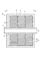
- the regenerator 10 ⁇ / b> A of the first embodiment includes a box-shaped container 20 having an internal space 201, such as a cylinder or a rectangle.
- the container 20 can be formed, for example with metals, such as stainless steel and iron. Or the container 20 can also be formed with ceramics, such as an alumina and ceramics.
- the container 20 is provided with a flow channel pipe 21 that penetrates the internal space 201.
- the channel pipe 21 can take, for example, a straight tube shape, a crank shape, a U shape, an L shape, a serpentine structure, a parallel structure, a spiral shape, and the like.
- a straight tubular flow channel 21 is shown, and a heat medium flows through the flow channel 211.
- the flow path piping 21 can be formed with metals, such as iron, stainless steel, copper, and aluminum, for example.
- the channel pipe 21 can be formed of ceramic such as alumina, zirconia, magnesia, silicon carbide, aluminum nitride, silicon nitride, graphite.
- the heat storage body 30 is accommodated in the internal space 201 of the container 20 and is in contact with the outer side surface 212 of the flow path pipe 21.
- the heat storage body 30 includes a latent heat storage material 31 and a plurality of honeycomb bodies 32 immersed in the latent heat storage material 31.
- the latent heat storage material 31 is, for example, powder before being heated for the first time, and has a property of being liquefied when heated by passing a high-temperature heat medium through the flow path pipe 21.
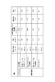
- the latent heat storage material 31 for example, sodium nitrate + potassium nitrate, magnesium chloride hexahydrate, calcium chloride hexahydrate, naphthalene, or the like can be used as shown in FIG. Note that once the latent heat storage material 31 is melted, it does not become a powder when solidified but becomes a lump. For this reason, when used after the second time, the latent heat storage material before melting is a massive solid.
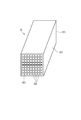
- the honeycomb body 32 includes, for example, a rectangular box-shaped housing 321, and a plurality of linear communication paths 322 are densely arranged in parallel inside the housing 321. Both ends of the communication path 322 are located on both opening surfaces 323 of the housing 321. Further, the communication path of the honeycomb body only needs to be oriented in the vertical direction, and may be linear or curved.
- the honeycomb body 32 can be formed of a metal such as iron, stainless steel, aluminum, or copper, for example. Or it can form with ceramics, such as silicon carbide, an alumina, a cordierite, and ceramics.
- the honeycomb body 32 is preferably formed of ceramic.
- the honeycomb body 32 has a convex portion 33 on at least one opening surface 323.
- the length of a part of the communication passages 322 is formed long, and a convex portion 331 is formed so as to protrude from the opening surface 323 in the flow direction.
- the convex portions 331 are provided on both opening surfaces 323, but may be provided only on one opening surface 323.
- the number of the communication paths 322 is not restricted to this.
- the honeycomb bodies 32 are aligned in the vertical direction inside the latent heat storage material 31 so that the communication directions of the communication paths 322 are parallel to each other.
- the convex portion 33 makes point contact with another honeycomb body 32 adjacent in the communication direction.
- a space S is generated between the two honeycomb bodies 32.
- the latent heat storage material 31 of the heat storage body 30 is heated, the latent heat storage material 31 is melted from a massive solid and changed into a liquid phase.
- the space S is provided between the plurality of honeycomb bodies 32, the latent heat storage material 31 inside each communication passage 322 of each honeycomb body 32 is heated and melted almost simultaneously, and is liquefied latent heat.
- the heat storage material 31 immediately starts convection and heats each honeycomb body 32.
- the heat accumulator 10A includes a flow path pipe 21 through which a heat medium can flow, a container 20 that covers the outer surface 212 of the flow path pipe 21 and has an internal space 201, and an outer surface of the flow path pipe 21 that is accommodated in the internal space 201.
- the heat storage body 30 is in contact with 212.
- the heat storage body 30 includes a latent heat storage material 31 and a plurality of honeycomb bodies 32 that are immersed in the latent heat storage material 31 and linear communication paths 322 are densely arranged in parallel.
- the honeycomb bodies 32 are aligned in the vertical direction so that the communication directions of the communication passages 322 are parallel to each other.
- the communication path 322 of the honeycomb body 32 is finely divided and immersed in the latent heat storage material 31.
- the latent heat storage material 31 inside each communication path 322 melts almost simultaneously, forming or increasing the space S by thermal expansion, and outside the communication path. Since it immediately flows out and convection can be started, it is difficult to rapidly raise the temperature after the latent heat storage material 31 is melted, and deterioration of the latent heat storage material 31 or damage to the honeycomb body 32 can be prevented.
- the convection can be freely performed if there is a space S between the opening surfaces 323 of the communication paths 322.
- the space S may be originally present or may be formed by thermal expansion of the latent heat storage material. Since the latent heat storage material 31 inside each communication path 322 melts almost simultaneously and forms or enlarges the space S by thermal expansion, it can immediately flow out of the communication path 322 and start convection. Alternatively, the latent heat storage material 31 can be prevented from being heated by convection using the space S between the honeycomb bodies 32.
- each communication path 322 of each honeycomb body 32 is arranged so as to face in the vertical direction, it is possible to make it difficult to block the upward flow of the warmed latent heat storage material 31 and to efficiently convection. .
- the honeycomb body 32 is made of ceramic.
- Various latent heat storage materials 31 are selected depending on the temperature range to be used, and some have corrosive properties. However, by using a chemically stable ceramic, the latent heat storage material 31 can be used stably without being corroded. be able to. Further, since ceramic has heat resistance, it can be used without being corroded even at high temperatures.
- the honeycomb body 32 is made of silicon carbide. Since silicon carbide has high heat resistance and is chemically stable among ceramics, it can be used without corrosion even at high temperatures.
- the plurality of honeycomb bodies 32 are in point contact with each other.
- the honeycomb bodies 32 are restrained from floating freely when the latent heat storage material 31 is melted.
- heat transfer can be promoted by heat conduction between the honeycomb bodies 32 before the latent heat storage material 31 is melted and convection is started.
- a space S can be formed between the honeycomb bodies 32, and convection can be promoted. Since the entire surface is not in contact, a sufficient space S necessary for convection can be formed.
- the point contact is preferably not limited to the opening surface 323 of the honeycomb body 32, and the space S can be secured by making point contact also on the side surface of the honeycomb body 32, and the convection of the latent heat storage material can be promoted.
- At least one opening surface 323 of the honeycomb body 32 has a convex portion.
- the convex portion can function to form a space S between the opening surfaces 323.
- the heat accumulator 10B of 2nd Embodiment shown in FIG. 5 is demonstrated.
- symbol is attached
- the convex portion 33 is provided on the opening surface 323 of the honeycomb body 32 and the space S is provided between the honeycomb bodies 32 (see FIG. 4), but the heat accumulator 10B of the second embodiment.
- the fracture surface 34 is provided on the opening surface 323 instead of providing the convex portion 33.
- At least one opening surface 323 of the honeycomb body 32 has a fracture surface 34. For this reason, since the opening surface 323 becomes a fracture surface 34 that is not a flat surface, the convex portions 341 of the fracture surface 34 of the honeycomb body 32 come into contact with each other to form a space S between the opening surfaces 323. And convection can be promoted.
- the heat accumulator of the present invention is not limited to the above-described embodiments, and appropriate modifications and improvements can be made.
- the heat accumulator of the present invention can be used as a heat accumulator that is used in various fields such as shortening the warm-up operation of an automobile and storing solar heat.
Landscapes
- Engineering & Computer Science (AREA)
- General Engineering & Computer Science (AREA)
- Physics & Mathematics (AREA)
- Thermal Sciences (AREA)
- Mechanical Engineering (AREA)
- Chemical & Material Sciences (AREA)
- Ceramic Engineering (AREA)
- Materials Engineering (AREA)
- Structural Engineering (AREA)
- Organic Chemistry (AREA)
- Dispersion Chemistry (AREA)
- Laminated Bodies (AREA)
- Exhaust Gas After Treatment (AREA)
Abstract
熱蓄熱材と、ハニカム体とを用いた蓄熱器において、潜熱蓄熱材が溶融した後に急昇温しにくくすることにより、潜熱蓄熱材の劣化あるいはハニカム体の破損が起こりにくい蓄熱器を提供する。 蓄熱器10Aは、熱媒体が流通可能な流路配管21と、流路配管21の外側面212を覆うとともに内部空間201を有する容器20と、内部空間201に収容され流路配管21の外側面212と接触する蓄熱体30を有する。蓄熱体30は、潜熱蓄熱材31と、潜熱蓄熱材31に浸漬され直線状の連通路322が並行に密集配列されたハニカム体32を有し、ハニカム体32は、各連通路322の連通方向が互いに並行となるように上下方向に配向して配列されている。このため、複数のハニカム体32に分けて潜熱蓄熱材31に浸漬することにより、ハニカム体32の連通路322が細かく分断されて潜熱蓄熱材31に浸漬される。これにより、流路配管21を流れる熱媒体によって加熱されると、各連通路322の内部の潜熱蓄熱材31がほぼ同時に溶融するので、潜熱蓄熱材31が溶融した後に急昇温しにくくして、潜熱蓄熱材31の劣化やハニカム体32の破損を防止できる。
Description
本発明は、例えば、自動車の暖機運転の短縮、太陽熱の蓄熱等、様々な分野で利用されている蓄熱器に関するものである。
特許文献1には、優れた伝熱効率を有する蓄熱装置として、過冷却蓄熱材を備え、当該過冷却蓄熱材の相変化に伴って放出される潜熱により対象物を加熱する蓄熱装置であって、過冷却蓄熱材を収容する容器と、過冷却状態の過冷却蓄熱材を発核させて相変化させる発核装置と、を備え、容器内には、複数の細孔を有する隔壁と、当該隔壁により区分けされた複数のセルと、が設けられていることを特徴とする蓄熱装置が記載されている。なお、過冷却蓄熱材とは、液相状態から温度を下げて、その温度が凝固点以下になっても液相のままで固化しない性質を有する潜熱蓄熱材である。
さらに、略水平な第1の隔壁と、この第1の隔壁に交差する第2の隔壁とによって、過冷却蓄熱材を収容する容器内が格子状のセルに区分けされていること、第1の隔壁、第2の隔壁および外周壁は、アルミナやSiC(シリコンカーバイド)等の多孔質の熱伝導体を押出し成形することにより、一体成形されることが記載されている。
このような格子状のセルを用いることによってこれらの隔壁に対して略垂直に成長した針状結晶と各隔壁との接触面積を増大できる結果、これらの隔壁を通じて過冷却蓄熱材の潜熱をより効率良く伝熱できることが記載されている。
このような格子状のセルを用いることによってこれらの隔壁に対して略垂直に成長した針状結晶と各隔壁との接触面積を増大できる結果、これらの隔壁を通じて過冷却蓄熱材の潜熱をより効率良く伝熱できることが記載されている。
しかしながら、潜熱蓄熱材は、大きな融解潜熱を有している代わりに液体の比熱がそれほど大きくない。特許文献1に開示された複数のセル(ハニカム体)と潜熱蓄熱材とが設けられた蓄熱装置は、潜熱蓄熱材が一旦溶融してしまうと熱を蓄える能力が大きくなく、熱源に近い部分では急昇温する。このため、潜熱蓄熱材の熱膨張によるセル(ハニカム体)の破損あるいは、潜熱蓄熱材の使用上限温度を超え、潜熱蓄熱材を劣化させるなどの問題がある。
本発明は、従来の問題を解決するためになされたもので、潜熱蓄熱材と、ハニカム体とを用いた蓄熱器において、潜熱蓄熱材が溶融した後に急昇温しにくくすることにより、潜熱蓄熱材の劣化あるいはハニカム体の破損が起こりにくい蓄熱器を提供することを目的とする。
前記課題を解決するための本発明の蓄熱器は、熱媒体が流通可能な流路配管と、前記流路配管の外側面を覆うとともに内部空間を有する容器と、前記内部空間に収容され、前記流路配管の外側面と接触する蓄熱体と、からなる蓄熱器において、前記蓄熱体は、潜熱蓄熱材と、前記潜熱蓄熱材に浸漬され、連通路が並行に密集配列されたハニカム体とからなり、前記各ハニカム体は、それぞれの前記各連通路の連通方向が互いに並行となるように上下方向に配向し配列されているものである。
本発明の蓄熱器は、熱媒体が流通可能な流路配管と、流路配管の外側面を覆うとともに内部空間を有する容器と、内部空間に収容され流路配管の外側面と接触する蓄熱体を有する。
蓄熱体は、潜熱蓄熱材と、潜熱蓄熱材に浸漬され連通路が並行に密集配列されたハニカム体を有し、ハニカム体は、各連通路の連通方向が互いに並行となるように上下方向に配向し配列されている。
蓄熱体は、潜熱蓄熱材と、潜熱蓄熱材に浸漬され連通路が並行に密集配列されたハニカム体を有し、ハニカム体は、各連通路の連通方向が互いに並行となるように上下方向に配向し配列されている。
このため、複数のハニカム体に分けて潜熱蓄熱材に浸漬することにより、ハニカム体の連通路が細かく分断されて潜熱蓄熱材に浸漬される。これにより、流路配管を流れる熱媒体によって加熱されると、各連通路の内部の潜熱蓄熱材がほぼ同時に溶融することができるので、潜熱蓄熱材が溶融した後に急昇温しにくくして、潜熱蓄熱材の劣化あるいはハニカム体の破損を防止することができる。
また、各ハニカム体の各連通路は、連通方向が互いに並行ではあるが互いに分断されているので蓄熱材が溶融し熱膨張することによって、各連通路の開口面の間には、空間を形成することができる。このため、各連通路の内部の溶融した潜熱蓄熱材は、ハニカム体の外部にすぐに流出することができ、連通路または、ハニカム体の間の空間を利用して対流するので、潜熱蓄熱材が局部的に加熱されることを防止することができる。
ハニカム体の連通路は、太さが一定の孔であるので、くびれた部分がなく潜熱蓄熱材の対流の抵抗となりにくいので、潜熱蓄熱材を効率良く対流させることができる。
また、各ハニカム体の各連通路は、連通方向が互いに並行ではあるが互いに分断されているので蓄熱材が溶融し熱膨張することによって、各連通路の開口面の間には、空間を形成することができる。このため、各連通路の内部の溶融した潜熱蓄熱材は、ハニカム体の外部にすぐに流出することができ、連通路または、ハニカム体の間の空間を利用して対流するので、潜熱蓄熱材が局部的に加熱されることを防止することができる。
ハニカム体の連通路は、太さが一定の孔であるので、くびれた部分がなく潜熱蓄熱材の対流の抵抗となりにくいので、潜熱蓄熱材を効率良く対流させることができる。
また、各ハニカム体は互いに並行に上下方向に配向するように配列されているので、ハニカム体の間に潜熱蓄熱材の対流に要する空間を形成し、対流を促進することができる。
さらに、各ハニカム体の各連通路が、上下方向を向くように配列しているので、暖められた潜熱蓄熱材の上昇流を遮りにくくすることができ、効率良く対流することができる。
さらに、各ハニカム体の各連通路が、上下方向を向くように配列しているので、暖められた潜熱蓄熱材の上昇流を遮りにくくすることができ、効率良く対流することができる。
また、本発明の蓄熱器は、以下の態様であることが望ましい。
(1)前記ハニカム体は、セラミック製である。
潜熱蓄熱材は、使用する温度域に応じて様々なものが選択され、腐食性を有するものがあるが、化学的に安定なセラミックを用いることにより、腐食されることなく安定して使用することができる。また、セラミックは、耐熱性を有しているので、高温でも腐食することなく使用することができる。
(1)前記ハニカム体は、セラミック製である。
潜熱蓄熱材は、使用する温度域に応じて様々なものが選択され、腐食性を有するものがあるが、化学的に安定なセラミックを用いることにより、腐食されることなく安定して使用することができる。また、セラミックは、耐熱性を有しているので、高温でも腐食することなく使用することができる。
(2)前記ハニカム体は、炭化珪素製である。
炭化珪素は、セラミックの中でも耐熱性が高く、化学的に安定であるので、高温でも腐食することなく使用することができる。
炭化珪素は、セラミックの中でも耐熱性が高く、化学的に安定であるので、高温でも腐食することなく使用することができる。
(3)前記複数のハニカム体は、互いに点接触している。
従って、複数のハニカム体が互いに点接触するように浸漬されていることによって、潜熱蓄熱材が溶融した際に、ハニカム体が自由に浮遊しないように拘束される。また、潜熱蓄熱材が溶融して対流を開始する前にも、ハニカム体間の熱伝導によって伝熱を促進することができる。さらに、点接触するように浸漬されていることによって、ハニカム体の間に空間を形成することができ、対流を促進することができる。
従って、複数のハニカム体が互いに点接触するように浸漬されていることによって、潜熱蓄熱材が溶融した際に、ハニカム体が自由に浮遊しないように拘束される。また、潜熱蓄熱材が溶融して対流を開始する前にも、ハニカム体間の熱伝導によって伝熱を促進することができる。さらに、点接触するように浸漬されていることによって、ハニカム体の間に空間を形成することができ、対流を促進することができる。
(4)前記ハニカム体の少なくとも一方の開口面は、凸部を有する。
開口面に設けられた凸部が、対面する開口面同士の間に充分な空間を形成するように機能することができるので、対流を促進することができる。
開口面に設けられた凸部が、対面する開口面同士の間に充分な空間を形成するように機能することができるので、対流を促進することができる。
(5)前記ハニカム体の少なくとも一方の開口面は、破断面を有する。
開口面は平坦な面ではない破断面であるので、破断面の凸部同士が接触することにより、対面する開口面同士の間に充分な空間を形成することができ、対流を促進することができる。
開口面は平坦な面ではない破断面であるので、破断面の凸部同士が接触することにより、対面する開口面同士の間に充分な空間を形成することができ、対流を促進することができる。
本発明では、蓄熱体は、潜熱蓄熱材と、潜熱蓄熱材に浸漬され直線状の連通路が並行に密集配列されたハニカム体を有するとともに、ハニカム体は、各連通路の連通方向が互いに並行となるように上下方向に配向して配列されている。このため、複数のハニカム体に分けて潜熱蓄熱材に浸漬することにより、ハニカム体の連通路が細かく分断されて潜熱蓄熱材に浸漬されるので、流路配管を流れる熱媒体によって加熱されると、潜熱蓄熱材が溶融し熱膨張することによって、ハニカム体間に隙間を形成し周辺に流出することができる。このため、潜熱蓄熱材が溶融した後に急昇温しにくくして、潜熱蓄熱材の劣化あるいはハニカム体の破損を防止することができるという効果を有する蓄熱器を提供できる。
本明細書において、上下とは重力の向きに対して定義される上下方向である。
(第1実施形態)
以下、本発明に係る第1実施形態の蓄熱器について、図面を用いて説明する。
図1に示すように、第1実施形態の蓄熱器10Aは、内部空間201を有する例えば円柱や矩形等の箱状の容器20を有する。容器20は、例えばステンレスや鉄等の金属で形成することができる。あるいは、容器20は、アルミナや陶磁器等のセラミックで形成することもできる。
(第1実施形態)
以下、本発明に係る第1実施形態の蓄熱器について、図面を用いて説明する。
図1に示すように、第1実施形態の蓄熱器10Aは、内部空間201を有する例えば円柱や矩形等の箱状の容器20を有する。容器20は、例えばステンレスや鉄等の金属で形成することができる。あるいは、容器20は、アルミナや陶磁器等のセラミックで形成することもできる。
容器20には、内部空間201を貫通する流路配管21が設けられている。流路配管21は、例えば直管状、クランク状、U字状、L字状、サーペンタイン構造、並列構造、螺旋状等の形状を取ることができる。図1では、直管状の流路配管21を示しており、流路211を熱媒体が流通する。
また、流路配管21は、例えば、鉄、ステンレス、銅、アルミニウム等の金属で形成することができる。あるいは、流路配管21は、アルミナ、ジルコニア、マグネシア、炭化珪素、窒化アルミニウム、窒化珪素、黒鉛等のセラミックで形成することもできる。
また、流路配管21は、例えば、鉄、ステンレス、銅、アルミニウム等の金属で形成することができる。あるいは、流路配管21は、アルミナ、ジルコニア、マグネシア、炭化珪素、窒化アルミニウム、窒化珪素、黒鉛等のセラミックで形成することもできる。
容器20の内部空間201には、蓄熱体30が収容されており、流路配管21の外側面212と接触している。
蓄熱体30は、潜熱蓄熱材31と、潜熱蓄熱材31に浸漬された複数個のハニカム体32を有する。
潜熱蓄熱材31は、最初に加熱される前は例えば粉体であり、流路配管21内を高熱の熱媒体が通過することにより加熱されると液化する性質を有する。潜熱蓄熱材31としては、図2に示すように、例えば、硝酸ナトリウム+硝酸カリウム、塩化マグネシウム六水和物、塩化カルシウム六水和物、ナフタリン等が使用できる。なお、一旦溶融した潜熱蓄熱材31は、凝固すると粉体にはならず、塊状になる。このため2回目以降に使用される際は、溶融前の潜熱蓄熱材は塊状の固体である。
蓄熱体30は、潜熱蓄熱材31と、潜熱蓄熱材31に浸漬された複数個のハニカム体32を有する。
潜熱蓄熱材31は、最初に加熱される前は例えば粉体であり、流路配管21内を高熱の熱媒体が通過することにより加熱されると液化する性質を有する。潜熱蓄熱材31としては、図2に示すように、例えば、硝酸ナトリウム+硝酸カリウム、塩化マグネシウム六水和物、塩化カルシウム六水和物、ナフタリン等が使用できる。なお、一旦溶融した潜熱蓄熱材31は、凝固すると粉体にはならず、塊状になる。このため2回目以降に使用される際は、溶融前の潜熱蓄熱材は塊状の固体である。
図3に示すように、ハニカム体32は、例えば矩形箱状の筐体321を有し、筐体321の内部には、直線状の複数の連通路322が並行に密集配列されている。連通路322の両端は、筐体321の両開口面323に位置する。
また、ハニカム体の連通路は、上下方向に配向していればよく、直線状であっても、湾曲していてもよい。
ハニカム体32は、例えば、鉄、ステンレス、アルミニウム、銅等の金属で形成することができる。あるいは、炭化珪素、アルミナ、コージェライト、陶磁器等のセラミックで形成することができる。ここでは、ハニカム体32はセラミックで形成するのが望ましい。さらに、ハニカム体32を炭化珪素で形成するのが一層望ましい。炭化珪素は熱伝導率が高く、耐熱性があり、化学的に安定な物質であるので好適に利用できる。
また、ハニカム体の連通路は、上下方向に配向していればよく、直線状であっても、湾曲していてもよい。
ハニカム体32は、例えば、鉄、ステンレス、アルミニウム、銅等の金属で形成することができる。あるいは、炭化珪素、アルミナ、コージェライト、陶磁器等のセラミックで形成することができる。ここでは、ハニカム体32はセラミックで形成するのが望ましい。さらに、ハニカム体32を炭化珪素で形成するのが一層望ましい。炭化珪素は熱伝導率が高く、耐熱性があり、化学的に安定な物質であるので好適に利用できる。
また、図4(A)~図4(C)に示すように、ハニカム体32は、少なくとも一方の開口面323に凸部33を有する。
図4(A)に示すハニカム体32では、一部の連通路322の長さが長く形成されており、開口面323から流通方向に突出して凸部331が形成されている。なお、ここでは、両開口面323に凸部331が設けられているが、一方の開口面323にのみ設けることもできる。また、2本の連通路322が突出する場合を例示したが、連通路322の本数は、これに限るものではない。
図4(A)に示すハニカム体32では、一部の連通路322の長さが長く形成されており、開口面323から流通方向に突出して凸部331が形成されている。なお、ここでは、両開口面323に凸部331が設けられているが、一方の開口面323にのみ設けることもできる。また、2本の連通路322が突出する場合を例示したが、連通路322の本数は、これに限るものではない。
図4(B)に示すハニカム体32は、全ての連通路322の長さが等しく、全体として平行四辺形に形成されている。このため、両開口面323において凸部332が形成される。
また、図4(C)に示すハニカム体32は、全ての連通路322の長さが等しく、幅方向の一端側において、連通路322が流通方向にずれている。このため、開口面323から突出する部分に凸部333が形成される。
また、図4(C)に示すハニカム体32は、全ての連通路322の長さが等しく、幅方向の一端側において、連通路322が流通方向にずれている。このため、開口面323から突出する部分に凸部333が形成される。
図1に示すように、各ハニカム体32は、潜熱蓄熱材31の内部において、それぞれの各連通路322の連通方向が互いに並行となるように上下方向に配向して配列されている。
前述したように、各ハニカム体32は凸部33を有しているので、ハニカム体32を並行に配列した際に、凸部33が連通方向に隣接する別のハニカム体32に点接触するので、両ハニカム体32の間に空間Sが生じる。
前述したように、各ハニカム体32は凸部33を有しているので、ハニカム体32を並行に配列した際に、凸部33が連通方向に隣接する別のハニカム体32に点接触するので、両ハニカム体32の間に空間Sが生じる。
従って、流路配管21に熱媒体を流して蓄熱体30の潜熱蓄熱材31加熱すると、潜熱蓄熱材31は塊状の固体から溶融して液体に相変化する。このとき、複数のハニカム体32の間には空間Sが設けられているので、各ハニカム体32の各連通路322の内部の潜熱蓄熱材31が、ほぼ同時に加熱されて溶融し、液化した潜熱蓄熱材31がすぐに対流を開始し、各ハニカム体32を加熱する。
次に、蓄熱器10Aの作用効果について説明する。
蓄熱器10Aは、熱媒体が流通可能な流路配管21と、流路配管21の外側面212を覆うとともに内部空間201を有する容器20と、内部空間201に収容され流路配管21の外側面212と接触する蓄熱体30を有する。
蓄熱体30は、潜熱蓄熱材31と、潜熱蓄熱材31に浸漬され直線状の連通路322が並行に密集配列された複数のハニカム体32を有する。そして、ハニカム体32は、各連通路322の連通方向が互いに並行となるように上下方向に配向して配列されている。
蓄熱器10Aは、熱媒体が流通可能な流路配管21と、流路配管21の外側面212を覆うとともに内部空間201を有する容器20と、内部空間201に収容され流路配管21の外側面212と接触する蓄熱体30を有する。
蓄熱体30は、潜熱蓄熱材31と、潜熱蓄熱材31に浸漬され直線状の連通路322が並行に密集配列された複数のハニカム体32を有する。そして、ハニカム体32は、各連通路322の連通方向が互いに並行となるように上下方向に配向して配列されている。
このため、複数のハニカム体32に分けて潜熱蓄熱材31に浸漬することにより、ハニカム体32の連通路322が細かく分断されて潜熱蓄熱材31に浸漬される。これにより、流路配管21を流れる熱媒体によって加熱されると、各連通路322の内部の潜熱蓄熱材31がほぼ同時に溶融し、熱膨張によって空間Sを形成または大きくするとともに連通路の外部にすぐに流出し対流を始めることができるので、潜熱蓄熱材31が溶融した後に急昇温しにくくして、潜熱蓄熱材31の劣化あるいはハニカム体32の破損を防止することができる。
また、各ハニカム体32の各連通路322は、連通方向が互いに並行となっているので、各連通路322の開口面323の間には、空間Sがあると自由に対流することができる。空間Sは、もともとあってもよく、潜熱蓄熱材の熱膨張によって形成されてもよい。各連通路322の内部の潜熱蓄熱材31は、ほぼ同時に溶融し、熱膨張によって空間Sを形成または大きくするとともに連通路322の外部にすぐに流出し対流を始めることができるので、連通路322またはハニカム体32の間の空間Sを利用して対流し、潜熱蓄熱材31が加熱されることを防止することができる。
また、各ハニカム体32は互いに並行に配列されて潜熱蓄熱材31に浸漬され、互いに対面しあうので、ハニカム体32の間に潜熱蓄熱材31の対流に要する空間Sがあると、効率良く対流することができる。
さらに、各ハニカム体32の各連通路322は、上下方向を向くように配列しているので、暖められた潜熱蓄熱材31の上昇流を遮りにくくすることができ、効率良く対流することができる。
また、各ハニカム体32は互いに並行に配列されて潜熱蓄熱材31に浸漬され、互いに対面しあうので、ハニカム体32の間に潜熱蓄熱材31の対流に要する空間Sがあると、効率良く対流することができる。
さらに、各ハニカム体32の各連通路322は、上下方向を向くように配列しているので、暖められた潜熱蓄熱材31の上昇流を遮りにくくすることができ、効率良く対流することができる。
また、蓄熱器10Aでは、ハニカム体32は、セラミック製である。
潜熱蓄熱材31は、使用する温度域に応じて様々なものが選択され、腐食性を有するものがあるが、化学的に安定なセラミックを用いることにより、腐食されることなく安定して使用することができる。また、セラミックは、耐熱性を有しているので、高温でも腐食することなく使用することができる。
潜熱蓄熱材31は、使用する温度域に応じて様々なものが選択され、腐食性を有するものがあるが、化学的に安定なセラミックを用いることにより、腐食されることなく安定して使用することができる。また、セラミックは、耐熱性を有しているので、高温でも腐食することなく使用することができる。
蓄熱器10Aでは、ハニカム体32は、炭化珪素製である。
炭化珪素は、セラミックの中でも耐熱性が高く、化学的に安定であるので、高温でも腐食することなく使用することができる。
炭化珪素は、セラミックの中でも耐熱性が高く、化学的に安定であるので、高温でも腐食することなく使用することができる。
蓄熱器10Aでは、複数のハニカム体32は、互いに点接触している。
複数のハニカム体32が互いに点接触するように浸漬されていることによって、潜熱蓄熱材31が溶融した際に、ハニカム体32が自由に浮遊しないよう拘束する。また、潜熱蓄熱材31が溶融して対流を開始する前にも、ハニカム体32間の熱伝導によって伝熱を促進することができる。さらに、点接触するように浸漬されていることによって、ハニカム体32の間に空間Sを形成することができ、対流を促進することができる。全面が接触していないので、対流に必要な充分な空間Sを形成することができる。なお、点接触が好ましいのは、ハニカム体32の開口面323に限定されず、ハニカム体32の側面でも点接触することによって空間Sを確保でき、潜熱蓄熱材の対流を促進することができる。
複数のハニカム体32が互いに点接触するように浸漬されていることによって、潜熱蓄熱材31が溶融した際に、ハニカム体32が自由に浮遊しないよう拘束する。また、潜熱蓄熱材31が溶融して対流を開始する前にも、ハニカム体32間の熱伝導によって伝熱を促進することができる。さらに、点接触するように浸漬されていることによって、ハニカム体32の間に空間Sを形成することができ、対流を促進することができる。全面が接触していないので、対流に必要な充分な空間Sを形成することができる。なお、点接触が好ましいのは、ハニカム体32の開口面323に限定されず、ハニカム体32の側面でも点接触することによって空間Sを確保でき、潜熱蓄熱材の対流を促進することができる。
蓄熱器10Aでは、ハニカム体32の少なくとも一方の開口面323は、凸部を有する。
このため、凸部が開口面323の間に空間Sを形成するように機能することができる。
このため、凸部が開口面323の間に空間Sを形成するように機能することができる。
(第2実施形態)
次に、図5に示す第2実施形態の蓄熱器10Bについて説明する。
なお、前述した第1実施形態の蓄熱器10Aと共通する部位には同じ符号を付して、重複する説明を省略することとする。
第1実施形態の蓄熱器10Aでは、ハニカム体32の開口面323に凸部33を設けてハニカム体32の間に空間Sを設けた(図4参照)が、第2実施形態の蓄熱器10Bでは、図5に示すように、凸部33を設ける代わりに、開口面323に破断面34を設けた。
次に、図5に示す第2実施形態の蓄熱器10Bについて説明する。
なお、前述した第1実施形態の蓄熱器10Aと共通する部位には同じ符号を付して、重複する説明を省略することとする。
第1実施形態の蓄熱器10Aでは、ハニカム体32の開口面323に凸部33を設けてハニカム体32の間に空間Sを設けた(図4参照)が、第2実施形態の蓄熱器10Bでは、図5に示すように、凸部33を設ける代わりに、開口面323に破断面34を設けた。
蓄熱器10Bでは、ハニカム体32の少なくとも一方の開口面323は、破断面34を有する。
このため、開口面323は平坦な面ではない破断面34となるので、ハニカム体32の破断面34の凸部341同士が接触することにより、開口面323の間に空間Sを形成することができ、対流を促進することができる。
このため、開口面323は平坦な面ではない破断面34となるので、ハニカム体32の破断面34の凸部341同士が接触することにより、開口面323の間に空間Sを形成することができ、対流を促進することができる。
本発明の蓄熱器は、前述した各実施形態に限定されるものでなく、適宜な変形、改良等が可能である。
本発明の蓄熱器は、例えば、自動車の暖機運転の短縮、太陽熱の蓄熱等、様々な分野で利用されている蓄熱器として利用することができる。
10A、10B 蓄熱器
20 容器
201 内部空間
21 流路配管
212 外側面
30 蓄熱体
31 潜熱蓄熱材
32 ハニカム体
322 連通路
323 開口面
33 凸部
34 破断面
20 容器
201 内部空間
21 流路配管
212 外側面
30 蓄熱体
31 潜熱蓄熱材
32 ハニカム体
322 連通路
323 開口面
33 凸部
34 破断面
Claims (6)
- 熱媒体が流通可能な流路配管と、
前記流路配管の外側面を覆うとともに内部空間を有する容器と、
前記内部空間に収容され、前記流路配管の外側面と接触する蓄熱体と、からなる蓄熱器において、
前記蓄熱体は、潜熱蓄熱材と、前記潜熱蓄熱材に浸漬され、連通路が並行に密集配列されたハニカム体とからなり、
前記各ハニカム体は、それぞれの前記各連通路の連通方向が互いに並行となるように上下方向に配向して配列されていることを特徴とする蓄熱器。 - 前記ハニカム体は、セラミック製であることを特徴とする請求項1に記載の蓄熱器。
- 前記ハニカム体は、炭化珪素製であることを特徴とする請求項2に記載の蓄熱器。
- 前記複数のハニカム体は、互いに点接触していることを特徴とする請求項1~請求項3のうちのいずれか一項に記載の蓄熱器。
- 前記ハニカム体の少なくとも一方の開口面は、凸部を有することを特徴とする請求項1~請求項4のうちのいずれか一項に記載の蓄熱器。
- 前記ハニカム体の少なくとも一方の開口面は、破断面を有することを特徴とする請求項1~請求項4のうちのいずれか一項に記載の蓄熱器。
Applications Claiming Priority (2)
| Application Number | Priority Date | Filing Date | Title |
|---|---|---|---|
| JP2014040509A JP2015166638A (ja) | 2014-03-03 | 2014-03-03 | 蓄熱器 |
| JP2014-040509 | 2014-03-03 |
Publications (1)
| Publication Number | Publication Date |
|---|---|
| WO2015133380A1 true WO2015133380A1 (ja) | 2015-09-11 |
Family
ID=54055188
Family Applications (1)
| Application Number | Title | Priority Date | Filing Date |
|---|---|---|---|
| PCT/JP2015/055734 Ceased WO2015133380A1 (ja) | 2014-03-03 | 2015-02-27 | 蓄熱器 |
Country Status (2)
| Country | Link |
|---|---|
| JP (1) | JP2015166638A (ja) |
| WO (1) | WO2015133380A1 (ja) |
Cited By (1)
| Publication number | Priority date | Publication date | Assignee | Title |
|---|---|---|---|---|
| CN110174017A (zh) * | 2019-04-30 | 2019-08-27 | 东南大学 | 一种相变储能装置及热量循环利用系统 |
Citations (10)
| Publication number | Priority date | Publication date | Assignee | Title |
|---|---|---|---|---|
| JPS6162760A (ja) * | 1984-09-04 | 1986-03-31 | 株式会社日立製作所 | 蓄冷式膨張機のピストンおよびその製法 |
| JPS61261388A (ja) * | 1985-05-15 | 1986-11-19 | Nippon Denso Co Ltd | 蓄熱装置 |
| JPH0297895A (ja) * | 1988-10-03 | 1990-04-10 | Agency Of Ind Science & Technol | 蓄熱器 |
| JPH05306389A (ja) * | 1992-04-28 | 1993-11-19 | Takashi Nishigori | 蓄熱材 |
| JPH072739U (ja) * | 1993-05-20 | 1995-01-17 | 大阪瓦斯株式会社 | 蓄熱式交番燃焼装置 |
| JP2001012804A (ja) * | 1999-06-29 | 2001-01-19 | Energy Support Corp | 蓄熱材の充填方法 |
| JP2003502614A (ja) * | 1999-06-18 | 2003-01-21 | イエダ・リサーチ・アンド・デベロツプメント・カンパニー・リミテツド | 高温の熱を蓄積する安全システム |
| US20080093577A1 (en) * | 2006-06-21 | 2008-04-24 | Khraishi Tariq A | Metal-carbon nanotube composites for enhanced thermal conductivity for demanding or critical applications |
| JP2010169382A (ja) * | 2008-12-26 | 2010-08-05 | Sumitomo Electric Ind Ltd | 蓄熱器及び蓄熱器における熱交換方法 |
| JP2013228189A (ja) * | 2012-03-30 | 2013-11-07 | Ngk Insulators Ltd | 熱交換部材 |
-
2014
- 2014-03-03 JP JP2014040509A patent/JP2015166638A/ja active Pending
-
2015
- 2015-02-27 WO PCT/JP2015/055734 patent/WO2015133380A1/ja not_active Ceased
Patent Citations (10)
| Publication number | Priority date | Publication date | Assignee | Title |
|---|---|---|---|---|
| JPS6162760A (ja) * | 1984-09-04 | 1986-03-31 | 株式会社日立製作所 | 蓄冷式膨張機のピストンおよびその製法 |
| JPS61261388A (ja) * | 1985-05-15 | 1986-11-19 | Nippon Denso Co Ltd | 蓄熱装置 |
| JPH0297895A (ja) * | 1988-10-03 | 1990-04-10 | Agency Of Ind Science & Technol | 蓄熱器 |
| JPH05306389A (ja) * | 1992-04-28 | 1993-11-19 | Takashi Nishigori | 蓄熱材 |
| JPH072739U (ja) * | 1993-05-20 | 1995-01-17 | 大阪瓦斯株式会社 | 蓄熱式交番燃焼装置 |
| JP2003502614A (ja) * | 1999-06-18 | 2003-01-21 | イエダ・リサーチ・アンド・デベロツプメント・カンパニー・リミテツド | 高温の熱を蓄積する安全システム |
| JP2001012804A (ja) * | 1999-06-29 | 2001-01-19 | Energy Support Corp | 蓄熱材の充填方法 |
| US20080093577A1 (en) * | 2006-06-21 | 2008-04-24 | Khraishi Tariq A | Metal-carbon nanotube composites for enhanced thermal conductivity for demanding or critical applications |
| JP2010169382A (ja) * | 2008-12-26 | 2010-08-05 | Sumitomo Electric Ind Ltd | 蓄熱器及び蓄熱器における熱交換方法 |
| JP2013228189A (ja) * | 2012-03-30 | 2013-11-07 | Ngk Insulators Ltd | 熱交換部材 |
Cited By (2)
| Publication number | Priority date | Publication date | Assignee | Title |
|---|---|---|---|---|
| CN110174017A (zh) * | 2019-04-30 | 2019-08-27 | 东南大学 | 一种相变储能装置及热量循环利用系统 |
| CN110174017B (zh) * | 2019-04-30 | 2021-03-19 | 东南大学 | 一种相变储能装置及热量循环利用系统 |
Also Published As
| Publication number | Publication date |
|---|---|
| JP2015166638A (ja) | 2015-09-24 |
Similar Documents
| Publication | Publication Date | Title |
|---|---|---|
| AU2010330335B2 (en) | Heat transfer tube | |
| JP7206245B2 (ja) | 相変化材料を使用する蓄熱式熱交換器構造 | |
| JP6324150B2 (ja) | 熱交換部材、およびセラミックス構造体 | |
| JP5819838B2 (ja) | 熱交換部材 | |
| Du et al. | Towards improving charge/discharge rate of latent heat thermal energy storage (LHTES) by embedding metal foams in phase change materials (PCMs) | |
| US11719489B2 (en) | Heat exchanger | |
| KR20030058784A (ko) | 열교환장치 | |
| CN110006274A (zh) | 热交换部件及热交换器 | |
| JPWO2013111815A1 (ja) | 熱輸送装置 | |
| CN108071545A (zh) | 热交换器 | |
| JP2018179403A (ja) | ヒートパイプ | |
| WO2015133381A1 (ja) | 蓄熱器 | |
| JP2013228189A (ja) | 熱交換部材 | |
| JP2017036841A (ja) | 蓄熱器 | |
| JP2015166638A (ja) | 蓄熱器 | |
| CN114909932A (zh) | 热交换部件、热交换器及热传导部件 | |
| CN110822969B (zh) | 一种储热装置 | |
| JP2013194927A (ja) | 蓄熱式熱交換器及びそれを用いた入解熱方法 | |
| JP2018179487A (ja) | ヒートパイプ | |
| Park et al. | Thermal performance of a heat pipe with two dissimilar condensers for a medium-temperature thermal storage system | |
| JP2016035347A (ja) | 扁平状蓄熱器、扁平状蓄熱器を備えた蓄熱器ユニット及び蓄熱器ユニットを備えた蓄熱装置 | |
| RU2457417C1 (ru) | Металлическая тепловая труба плоского типа | |
| CN114961931A (zh) | 热交换部件、热交换器及热传导部件 | |
| JP2025108967A (ja) | 蓄熱装置 | |
| JP2010169382A (ja) | 蓄熱器及び蓄熱器における熱交換方法 |
Legal Events
| Date | Code | Title | Description |
|---|---|---|---|
| 121 | Ep: the epo has been informed by wipo that ep was designated in this application |
Ref document number: 15758091 Country of ref document: EP Kind code of ref document: A1 |
|
| NENP | Non-entry into the national phase |
Ref country code: DE |
|
| 122 | Ep: pct application non-entry in european phase |
Ref document number: 15758091 Country of ref document: EP Kind code of ref document: A1 |