WO2015133291A1 - アクチュエータ及びロボットアーム装置 - Google Patents
アクチュエータ及びロボットアーム装置 Download PDFInfo
- Publication number
- WO2015133291A1 WO2015133291A1 PCT/JP2015/054675 JP2015054675W WO2015133291A1 WO 2015133291 A1 WO2015133291 A1 WO 2015133291A1 JP 2015054675 W JP2015054675 W JP 2015054675W WO 2015133291 A1 WO2015133291 A1 WO 2015133291A1
- Authority
- WO
- WIPO (PCT)
- Prior art keywords
- unit
- encoder
- input shaft
- angle
- rotation
- Prior art date
Links
Images


Classifications
-
- H—ELECTRICITY
- H02—GENERATION; CONVERSION OR DISTRIBUTION OF ELECTRIC POWER
- H02K—DYNAMO-ELECTRIC MACHINES
- H02K7/00—Arrangements for handling mechanical energy structurally associated with dynamo-electric machines, e.g. structural association with mechanical driving motors or auxiliary dynamo-electric machines
- H02K7/10—Structural association with clutches, brakes, gears, pulleys or mechanical starters
- H02K7/116—Structural association with clutches, brakes, gears, pulleys or mechanical starters with gears
-
- B—PERFORMING OPERATIONS; TRANSPORTING
- B25—HAND TOOLS; PORTABLE POWER-DRIVEN TOOLS; MANIPULATORS
- B25J—MANIPULATORS; CHAMBERS PROVIDED WITH MANIPULATION DEVICES
- B25J13/00—Controls for manipulators
- B25J13/08—Controls for manipulators by means of sensing devices, e.g. viewing or touching devices
- B25J13/088—Controls for manipulators by means of sensing devices, e.g. viewing or touching devices with position, velocity or acceleration sensors
-
- B—PERFORMING OPERATIONS; TRANSPORTING
- B25—HAND TOOLS; PORTABLE POWER-DRIVEN TOOLS; MANIPULATORS
- B25J—MANIPULATORS; CHAMBERS PROVIDED WITH MANIPULATION DEVICES
- B25J9/00—Programme-controlled manipulators
- B25J9/06—Programme-controlled manipulators characterised by multi-articulated arms
-
- B—PERFORMING OPERATIONS; TRANSPORTING
- B25—HAND TOOLS; PORTABLE POWER-DRIVEN TOOLS; MANIPULATORS
- B25J—MANIPULATORS; CHAMBERS PROVIDED WITH MANIPULATION DEVICES
- B25J9/00—Programme-controlled manipulators
- B25J9/10—Programme-controlled manipulators characterised by positioning means for manipulator elements
- B25J9/12—Programme-controlled manipulators characterised by positioning means for manipulator elements electric
- B25J9/126—Rotary actuators
-
- B—PERFORMING OPERATIONS; TRANSPORTING
- B25—HAND TOOLS; PORTABLE POWER-DRIVEN TOOLS; MANIPULATORS
- B25J—MANIPULATORS; CHAMBERS PROVIDED WITH MANIPULATION DEVICES
- B25J9/00—Programme-controlled manipulators
- B25J9/16—Programme controls
- B25J9/1628—Programme controls characterised by the control loop
- B25J9/1641—Programme controls characterised by the control loop compensation for backlash, friction, compliance, elasticity in the joints
-
- G—PHYSICS
- G01—MEASURING; TESTING
- G01D—MEASURING NOT SPECIALLY ADAPTED FOR A SPECIFIC VARIABLE; ARRANGEMENTS FOR MEASURING TWO OR MORE VARIABLES NOT COVERED IN A SINGLE OTHER SUBCLASS; TARIFF METERING APPARATUS; MEASURING OR TESTING NOT OTHERWISE PROVIDED FOR
- G01D5/00—Mechanical means for transferring the output of a sensing member; Means for converting the output of a sensing member to another variable where the form or nature of the sensing member does not constrain the means for converting; Transducers not specially adapted for a specific variable
- G01D5/02—Mechanical means for transferring the output of a sensing member; Means for converting the output of a sensing member to another variable where the form or nature of the sensing member does not constrain the means for converting; Transducers not specially adapted for a specific variable using mechanical means
- G01D5/04—Mechanical means for transferring the output of a sensing member; Means for converting the output of a sensing member to another variable where the form or nature of the sensing member does not constrain the means for converting; Transducers not specially adapted for a specific variable using mechanical means using levers; using cams; using gearing
-
- G—PHYSICS
- G01—MEASURING; TESTING
- G01D—MEASURING NOT SPECIALLY ADAPTED FOR A SPECIFIC VARIABLE; ARRANGEMENTS FOR MEASURING TWO OR MORE VARIABLES NOT COVERED IN A SINGLE OTHER SUBCLASS; TARIFF METERING APPARATUS; MEASURING OR TESTING NOT OTHERWISE PROVIDED FOR
- G01D5/00—Mechanical means for transferring the output of a sensing member; Means for converting the output of a sensing member to another variable where the form or nature of the sensing member does not constrain the means for converting; Transducers not specially adapted for a specific variable
- G01D5/12—Mechanical means for transferring the output of a sensing member; Means for converting the output of a sensing member to another variable where the form or nature of the sensing member does not constrain the means for converting; Transducers not specially adapted for a specific variable using electric or magnetic means
- G01D5/14—Mechanical means for transferring the output of a sensing member; Means for converting the output of a sensing member to another variable where the form or nature of the sensing member does not constrain the means for converting; Transducers not specially adapted for a specific variable using electric or magnetic means influencing the magnitude of a current or voltage
- G01D5/142—Mechanical means for transferring the output of a sensing member; Means for converting the output of a sensing member to another variable where the form or nature of the sensing member does not constrain the means for converting; Transducers not specially adapted for a specific variable using electric or magnetic means influencing the magnitude of a current or voltage using Hall-effect devices
- G01D5/145—Mechanical means for transferring the output of a sensing member; Means for converting the output of a sensing member to another variable where the form or nature of the sensing member does not constrain the means for converting; Transducers not specially adapted for a specific variable using electric or magnetic means influencing the magnitude of a current or voltage using Hall-effect devices influenced by the relative movement between the Hall device and magnetic fields
-
- G—PHYSICS
- G01—MEASURING; TESTING
- G01D—MEASURING NOT SPECIALLY ADAPTED FOR A SPECIFIC VARIABLE; ARRANGEMENTS FOR MEASURING TWO OR MORE VARIABLES NOT COVERED IN A SINGLE OTHER SUBCLASS; TARIFF METERING APPARATUS; MEASURING OR TESTING NOT OTHERWISE PROVIDED FOR
- G01D5/00—Mechanical means for transferring the output of a sensing member; Means for converting the output of a sensing member to another variable where the form or nature of the sensing member does not constrain the means for converting; Transducers not specially adapted for a specific variable
- G01D5/12—Mechanical means for transferring the output of a sensing member; Means for converting the output of a sensing member to another variable where the form or nature of the sensing member does not constrain the means for converting; Transducers not specially adapted for a specific variable using electric or magnetic means
- G01D5/244—Mechanical means for transferring the output of a sensing member; Means for converting the output of a sensing member to another variable where the form or nature of the sensing member does not constrain the means for converting; Transducers not specially adapted for a specific variable using electric or magnetic means influencing characteristics of pulses or pulse trains; generating pulses or pulse trains
- G01D5/245—Mechanical means for transferring the output of a sensing member; Means for converting the output of a sensing member to another variable where the form or nature of the sensing member does not constrain the means for converting; Transducers not specially adapted for a specific variable using electric or magnetic means influencing characteristics of pulses or pulse trains; generating pulses or pulse trains using a variable number of pulses in a train
- G01D5/2451—Incremental encoders
-
- H—ELECTRICITY
- H02—GENERATION; CONVERSION OR DISTRIBUTION OF ELECTRIC POWER
- H02K—DYNAMO-ELECTRIC MACHINES
- H02K11/00—Structural association of dynamo-electric machines with electric components or with devices for shielding, monitoring or protection
- H02K11/20—Structural association of dynamo-electric machines with electric components or with devices for shielding, monitoring or protection for measuring, monitoring, testing, protecting or switching
- H02K11/21—Devices for sensing speed or position, or actuated thereby
- H02K11/215—Magnetic effect devices, e.g. Hall-effect or magneto-resistive elements
-
- H—ELECTRICITY
- H02—GENERATION; CONVERSION OR DISTRIBUTION OF ELECTRIC POWER
- H02P—CONTROL OR REGULATION OF ELECTRIC MOTORS, ELECTRIC GENERATORS OR DYNAMO-ELECTRIC CONVERTERS; CONTROLLING TRANSFORMERS, REACTORS OR CHOKE COILS
- H02P6/00—Arrangements for controlling synchronous motors or other dynamo-electric motors using electronic commutation dependent on the rotor position; Electronic commutators therefor
- H02P6/14—Electronic commutators
- H02P6/16—Circuit arrangements for detecting position
-
- G—PHYSICS
- G05—CONTROLLING; REGULATING
- G05B—CONTROL OR REGULATING SYSTEMS IN GENERAL; FUNCTIONAL ELEMENTS OF SUCH SYSTEMS; MONITORING OR TESTING ARRANGEMENTS FOR SUCH SYSTEMS OR ELEMENTS
- G05B2219/00—Program-control systems
- G05B2219/30—Nc systems
- G05B2219/39—Robotics, robotics to robotics hand
- G05B2219/39191—Compensation for errors in mechanical components
Definitions
- This disclosure relates to an actuator and a robot arm device.
- Rotary encoders (hereinafter simply referred to as encoders) are widely used as sensor devices for detecting the rotation angle of members that are rotationally driven, such as electric steering in automobiles and joints of robotic devices.
- encoders are widely used as sensor devices for detecting the rotation angle of members that are rotationally driven, such as electric steering in automobiles and joints of robotic devices.
- various techniques have been proposed in order to further improve the detection accuracy.
- Patent Document 1 the rotation of the main rotation shaft is converted into the rotation of two detection shafts by a speed reducer having a different reduction ratio, and the rotation angle of each detection shaft is detected by an encoder, and the detected rotation angle is detected.
- a technique for detecting the rotation angle of the main rotation shaft with high accuracy by calculating the absolute angle of the main rotation shaft based on the difference between the two is disclosed.
- a relative angle encoder is arranged in a configuration in which a relative angle encoder is arranged on an input shaft of a reduction gear connected to a rotation shaft of a motor and an absolute angle encoder is arranged on an output shaft of the reduction gear. Is disclosed in which a relationship regarding an error that may occur between the detected value and the detected value of the absolute angle encoder is acquired in advance, and the detection result of the absolute angle encoder is corrected using the relationship regarding the error. ing.
- a robot apparatus used for medical use and the above-described electric steering are required to have high safety in terms of driving.
- the technologies described in Patent Documents 1 and 2 such safety viewpoints are not sufficiently studied. Therefore, the present disclosure proposes a new and improved actuator and robot arm device that can detect the rotation angle with high accuracy and can be driven more safely.
- a speed reducer that decelerates the rotational speed of the input shaft coupled to the rotational shaft of the motor at a predetermined reduction ratio and transmits the reduced speed to the output shaft, and a first absolute that detects the rotational angle of the input shaft.
- An actuator is provided that includes an angle encoder and a second absolute angle encoder that detects a rotation angle of the output shaft.
- an arm unit configured by connecting a plurality of links by a joint unit, a drive control unit that controls driving of an actuator provided in the joint unit based on a state of the joint unit,
- the actuator includes a speed reducer that decelerates the rotational speed of the input shaft coupled to the rotational shaft of the motor at a predetermined reduction ratio and transmits the reduced speed to the output shaft, and a first angle that detects the rotational angle of the input shaft.
- a robot arm device is provided that includes an absolute angle encoder and a second absolute angle encoder that detects a rotation angle of the output shaft.
- absolute angle encoders are provided on both the input shaft and the output shaft via the speed reducer.
- the rotation angle of the output shaft can be detected with high resolution by the absolute angle encoder of the input shaft.
- the rotation angle can be detected immediately when the power is turned on, it is possible to prevent unintended movement of the user accompanying the initial operation.
- FIG. 9 is an explanatory diagram for describing a pivot operation that is a specific example of an arm operation according to an embodiment of the present disclosure.
- the target to which the actuator according to the present disclosure can be applied is not limited to such an example, and the actuator is, for example, an electric surgical instrument used for surgery, an electric steering of an automobile, an electric playground equipment installed in an amusement park, etc.
- the present invention can be suitably applied to an apparatus that requires highly accurate angle detection from the viewpoint of safety.
- the actuator according to the present disclosure may be applied to a device that is required to detect an angle with high accuracy from the viewpoint of operability, such as a controller for a game or simulator that simulates a steering wheel of an automobile.
- FIG. 1 is an exploded perspective view showing the overall configuration of the actuator according to the present embodiment.
- the actuator 300 includes a motor 310, a speed reducer 320, two rotary encoders 330 and 340 (encoders 330 and 340), an output shaft 350, and a housing 360. .
- the rotation of the rotation shaft of the motor 310 is decelerated at a predetermined reduction ratio by the speed reducer 320 and is transmitted to the other member at the subsequent stage via the output shaft 350, thereby driving the other member. It will be.
- the encoders 330 and 340 detect the rotation angle of the rotation shaft of the motor 310 and the rotation angle of the rotation shaft of the output shaft 350, respectively.
- the rotation angle of the motor 310 is also the rotation angle of the input shaft of the speed reducer 320
- the rotation angle and rotation speed of the motor 310 are referred to as the rotation angle and rotation speed of the input shaft, respectively.
- the rotation angle and rotation speed of the rotation shaft in the output shaft 350 are also referred to as the rotation angle and rotation speed of the output shaft, respectively.
- the absolute angle encoders are arranged on both the input shaft and the output shaft via the speed reducer 320, thereby detecting the rotation angle of the output shaft with high accuracy and satisfying various requirements required for safety. It is to realize that.
- the motor 310 is a driving mechanism that generates a driving force by rotating a rotating shaft at a rotation speed corresponding to the control value when a predetermined control value (current value) is given.
- a brushless motor is used as the motor 310.
- a motor it is necessary to change the direction of a magnetic field by switching the direction of a current flowing in a coil in accordance with the rotation of a rotor provided in the motor.
- the switching of the current direction is not performed mechanically using a brush, but is electrically performed using a semiconductor switch or the like instead of the brush.
- a speed reducer 320 is connected to the rotating shaft of the motor 310.
- the speed reducer 320 transmits the rotational speed of the rotating shaft of the coupled motor 310 (that is, the rotational speed of the input shaft) to the output shaft 350 by decelerating at a predetermined reduction ratio.
- the configuration of the speed reducer 320 is not limited to a specific one, and various known types of speed reducers may be used as the speed reducer 320.
- the speed reducer 320 it is preferable to use, for example, a harmonic drive (registered trademark) capable of setting the speed reduction ratio with high accuracy.
- the specific configuration of the speed reducer 320 can be appropriately designed so as to transmit a desired rotational speed and torque to a member connected to the subsequent stage of the output shaft 350 in accordance with the configuration of the actuator 300.
- Encoder 330 detects the rotation angle of the input shaft (that is, the rotation angle of motor 310).
- the encoder 330 is an absolute angle encoder, and can detect the absolute angular position of the input shaft.
- the encoder 330 is also referred to as an input shaft encoder 330 or an absolute angle encoder 330. Since a specific configuration of the encoder 330 will be described below (1-2. Configuration of the encoder), detailed description thereof is omitted here.
- the encoder 330 may be an absolute angle encoder, and the configuration thereof is not limited to the configuration described below (1-2. Configuration of Encoder), and may be arbitrary.
- the motor 310 is a brushless motor
- a sensor for detecting the rotation of the rotor for example, a hall sensor for driving the motor
- the encoder 330 provided on the input shaft can also function as the Hall sensor for driving the motor.
- the motor 310 may be driven based on the rotation angle of the input shaft detected by the encoder 330, and the motor drive hall sensor may not be provided. Thereby, since the number of constituent members can be reduced, the actuator 300 can be reduced in size and cost.
- the rotation angle of the output shaft can be detected with high accuracy by the amount of the reduction gear 320 through the reduction ratio. For example, if the reduction ratio is 1: 100, when the rotation angle of the input shaft is detected between 0 (degrees) and 360 (degrees), the rotation angle of the output shaft is 0 (degrees) to 3.6 ( The degree). In other words, detecting the rotation angle of the input shaft corresponds to detecting the rotation angle of the output shaft by enlarging it by the reduction ratio. Accordingly, by detecting the rotation angle of the output shaft based on the detected value of the rotation angle of the input shaft by the encoder 330, the rotation angle of the output shaft can be detected with high resolution. A specific method for detecting the rotation angle of the output shaft based on the detected value of the rotation angle of the input shaft is described in ⁇ 2. A configuration of the rotation angle detection system will be described in detail below.
- Encoder 340 detects the rotation angle of the output shaft.
- the encoder 340 is an absolute angle encoder, and can detect the absolute angular position of the output shaft.
- the encoder 340 is also referred to as an output shaft encoder 340 or an absolute angle encoder 340.
- the encoder 340 may have the same configuration as that of the encoder 330.
- the configuration described in the following (1-2. Configuration of the encoder) can be suitably applied as the encoder 340.
- the present embodiment is not limited to such an example, and the encoder 340 may be an absolute angle encoder, and the configuration thereof may be arbitrary.
- the housing 360 has a substantially cylindrical shape, and each component is stored inside. In a state where each component is stored in the housing 360, the following ⁇ 6. It will be incorporated as an actuator that drives each part that accompanies rotational drive, such as a joint part of a robot arm device described in Application Example>.
- the actuator 300 may further include a configuration other than the illustrated configuration.
- the actuator 300 includes a driver circuit (driver IC (Integrated Circuit)) that rotates and drives the motor 310 by supplying a current to the motor 310, torque at the output shaft 350 (that is, output torque of the actuator 300 (generated torque)).
- driver circuit driver IC (Integrated Circuit)
- FIG. 2 is a schematic diagram illustrating a configuration example of the encoders 330 and 340 according to the present embodiment.
- FIG. 3 is an explanatory diagram for explaining the principle of angle detection by the encoders 330 and 340 according to the present embodiment.
- the encoders 330 and 340 are magnetic encoders configured by combining two magnets 331 magnetized with two poles and two Hall elements 332 and 333.
- the magnet 331 has a substantially annular shape, and has such a polarity that one end of the annular shape is an N pole and the other end is an S pole.
- the Hall elements 332 and 333 are provided at positions around the magnet 331 rotated 90 (degrees) with respect to the rotation of the magnet 331 around the center axis of the ring shape.
- the magnet 331 is connected so as to rotate together with the rotation axis (in this embodiment, the input shaft or the output shaft) that is a detection target with the annular central axis as a rotation axis. As the magnet 331 rotates, the magnetic field detected by the Hall elements 332 and 333 periodically changes.
- the horizontal axis represents the rotation angle ⁇ of the magnet 331 (that is, the rotation angle ⁇ of the rotation shaft to be detected), the vertical axis represents the outputs of the Hall elements 332 and 333, and the relationship between the two is plotted.
- the Hall elements 332 and 333 are disposed at positions rotated 90 (degrees) around the magnet 331, the output of the Hall elements 332 and 333 is 90 (degrees) as shown in FIG.
- the waveform is shifted by only the phase. That is, a sine curve (sin ⁇ ) is acquired by one Hall element 332, and a cosine curve (cos ⁇ ) is acquired by the other Hall element 333. Therefore, the rotation angle ⁇ can be calculated from the outputs of the Hall elements 332 and 333 by the following formula (1).
- the rotation angle of the magnet 331 (that is, the rotation angle of the rotation shaft to be detected) is set to 0 (degrees) to 360 (degrees) according to the outputs of the two hall elements 332 and 333. ) Can be uniquely determined. Therefore, for example, even at the moment when the power supply is once shut off and restarted, the rotation angle of the rotating shaft can be detected immediately by detecting the outputs of the Hall elements 332 and 333 at the time of starting.
- the configuration of the encoders 330 and 340 is not limited to such an example, and various encoders may be applied as long as they are absolute angle encoders.
- the absolute angle encoder including the magnet 331 and the Hall elements 332 and 333 as shown in FIG. 2 has a relatively simple configuration, and thus can be miniaturized and is excellent in terms of cost. Therefore, by using the absolute angle encoder having the configuration illustrated in FIG. 2 as the encoders 330 and 340, the actuator 300 can be configured to be smaller and cheaper.
- the encoders 330 and 340 are arranged on both the input shaft and the output shaft, and the rotation angle of the output shaft is detected based on the detected value of the rotation angle of the input shaft by the encoder 330.
- the rotation angle of the output shaft can be detected with high accuracy.
- FIG. 4 is a functional block diagram showing a schematic configuration of the rotation angle detection system according to the present embodiment.
- the rotation angle of the output shaft can be detected with high accuracy by the configuration illustrated in FIG. 4.
- the rotation angle detection system 3 includes an actuator 300 and a control unit 370 that performs predetermined processing based on detection values of encoders 330 and 340 of the actuator 300.
- the control unit 370 may be configured by various processors such as a CPU (Central Processing Unit), for example, and a predetermined process can be executed by the control unit 370 operating according to a predetermined program.
- the control unit 370 can calculate the rotation angle of the output shaft based on the detected value of the rotation angle of the input shaft by the encoder 330.
- the control unit 370 may perform other processes, for example, ⁇ 4. Processing for detecting a failure of the actuator 300 as described in >> About Detection of Failure may be performed.
- the control unit 370 may be configured integrally with the actuator 300, or may be provided as a separate member from the actuator 300 and perform various processes based on various information transmitted from the actuator 300.
- FIG. 4 schematically shows a part of the configuration of the actuator 300 for explanation.
- the illustrated input shaft encoder 330, brushless motor 310, speed reducer 320, and output shaft encoder 340 correspond to the encoder 330, motor 310, speed reducer 320, and encoder 340 shown in FIG. Description is omitted.
- the control unit 370 includes, as its functions, an output shaft angle information acquisition unit 371, a motor cumulative rotation number calculation unit 372, an input shaft angle information acquisition unit 373, an input shaft cumulative operation angle calculation unit 374, and an output shaft angle calculation unit 375. .
- a specific numerical value will be described as an example for easy understanding.
- the reduction ratio of the reducer 320 is 1: 100
- the detection value of the input shaft encoder 330 is 181 (degrees)
- the detection value of the output shaft encoder 340 is 19.6 (degrees).
- Each function of the control unit 370 will be described.
- these numerical values are merely examples, and in this embodiment, even if the reduction ratio of the speed reducer 320 and the detection values of the encoders 330 and 340 are other values, the output shaft The rotation angle can be calculated.
- the output shaft of the actuator 300 has 0 (degrees) to 360 ( Suppose that it rotates within the range of degrees. In driving the arm portion of the robot arm device, it is unlikely that the joint portion rotates 360 degrees or more (that is, one rotation or more), so even if such an assumption is made, it does not cause a big problem. Therefore, the detected value of the output shaft encoder 340 also detects the angle ⁇ (that is, the angle after being reset to 0 (degrees) beyond 360 (degrees)) in a state where the output shaft has made one rotation or more. It can be said that the angle of the output shaft is expressed in a state where the accumulated rotational speed of the output shaft is less than one rotation.
- the output shaft angle information acquisition unit 371 acquires information (output shaft angle information) about the rotation angle of the output shaft from the output shaft encoder 340.
- the output shaft angle information may be information about the detected value of the rotation angle of the output shaft detected by the output shaft encoder 340.
- the output shaft angle information acquisition unit 371 acquires information indicating that the detection value by the output shaft encoder 340 is 19.6 (degrees) as the output shaft angle information.
- the output shaft angle information acquisition unit 371 provides the acquired output shaft angle information to the motor cumulative rotation number calculation unit 372.
- the motor cumulative rotational speed calculation unit 372 calculates the cumulative rotational speed of the brushless motor 310 based on the output shaft angle information.
- the cumulative rotation speed of the brushless motor 310 is calculated by further dividing the detected value of the rotation angle of the output shaft by 360 (degrees), which is the rotation angle when the brushless motor 310 makes one rotation, divided by the reduction ratio. obtain.
- the cumulative number of rotations of the brushless motor 310 can be calculated as in the following formula (2).
- the rotational speed of the brushless motor 310 is calculated as 5.44 (rotation).
- the motor accumulated rotation number calculation unit 372 calculates the accumulated rotation number of the brushless motor 310 as an integer value by rounding down the decimal part.
- the motor accumulated rotation number calculation unit 372 can calculate the accumulated rotation number of the brushless motor 310 as 5 (rotation) based on the detected value of the rotation number on the output shaft.
- the motor cumulative rotation number calculation unit 372 provides information about the calculated cumulative rotation number of the brushless motor to the input shaft cumulative operation angle calculation unit 374.
- the input shaft angle information acquisition unit 373 acquires information about the rotation angle of the input shaft (input shaft angle information) from the input shaft encoder 330.
- the input shaft angle information may be information about the detected value of the rotation angle of the input shaft detected by the input shaft encoder 330.
- the input shaft angle information acquisition unit 373 acquires information indicating that the detected value by the input shaft encoder 330 is 181 (degrees) as the input shaft angle information.
- the input shaft angle information acquisition unit 373 provides the acquired input shaft angle information to the input shaft cumulative operation angle calculation unit 374.
- the input shaft cumulative operation angle calculation unit 374 calculates the cumulative operation angle of the input shaft based on the input shaft angle information and information on the cumulative rotation speed of the brushless motor 310.
- the cumulative operation angle of the input shaft is the cumulative rotation angle of the input shaft after the brushless motor 310 starts rotating.
- the cumulative operating angle of the input shaft is calculated by adding the detected value of the rotational angle of the input shaft to a value obtained by converting the cumulative rotational speed of the brushless motor 310 to a rotational angle (ie, multiplied by 360 (degrees)). obtain.
- the cumulative operating angle of the input shaft can be calculated as in the following mathematical formula (3).
- the input shaft cumulative operation angle calculation unit 374 provides the output shaft angle calculation unit 375 with information on the calculated cumulative rotation speed of the input shaft.
- the output shaft angle calculation unit 375 calculates the rotation angle of the output shaft based on the information about the cumulative rotation speed of the input shaft.
- the calculated value of the rotation angle of the output shaft can be calculated by dividing the cumulative rotation speed of the input shaft by the reduction ratio.
- the rotation angle of the output shaft can be calculated as the following mathematical formula (4).
- the output shaft angle calculation unit 375 uses the information about the calculated rotation angle of the output shaft as a final detection value of the rotation angle of the output shaft, and controls the drive of the drive unit provided with the actuator 300 ( For example, it transmits to the control apparatus 20) of FIG. In the control device, the state of each drive unit is recognized based on the received calculation value of the rotation angle of the output shaft, and a control amount for driving each drive unit is calculated.
- the accumulated rotation speed of the motor 310 is calculated using the detection value of the output shaft encoder 340, and the calculated accumulated rotation speed of the motor 310 is converted into the accumulated operation angle of the input shaft.
- the rotation angle of the output shaft is calculated.
- the detection value of the encoder 330 provided on the input shaft can be considered to be the detection of the rotation angle of the output shaft with high resolution because of the reduction ratio. Therefore, the rotation angle of the output shaft converted from the detection value (181 (degrees)) by the input shaft encoder 330 through the reduction ratio is more than the detection value (19.6 (degrees)) by the output shaft encoder 340. It can be said that the rotation angle of the output shaft is accurately represented.
- the detected value (181 (degrees)) by the input shaft encoder 330 is not sure how many times the input shaft is rotated to "181 (degrees)".
- the detection value (19.6 (degrees)) detected by the output shaft encoder 340 is 0 (assuming that the actuator 300 is applied to a joint provided in the arm of the robot arm device as described above. It can be determined that the angle is between degrees and 360 degrees. Therefore, in this embodiment, by calculating the cumulative number of rotations of the motor 310 from the detection value by the output shaft encoder 340, the detection value (181 (degrees)) by the input shaft encoder 330 is changed to the input shaft (motor 310). It is determined how many times the rotation is “181 (degrees)”.
- the cumulative rotational operation angle of the input shaft can be calculated, so the rotational angle of the output shaft is detected based on the rotational angle of the input shaft that is considered to represent the rotational angle of the output shaft with higher accuracy. It becomes possible to do.
- the absolute angle encoder including the magnet 331 and the hall elements 332 and 333 as shown in FIG. 2 is simple in structure and excellent in cost, but the detection accuracy of the angle is not so high. It is known.
- the output shaft is highly accurate. It is possible to calculate the rotation angle. Accordingly, the actuator 300 can be made smaller and less expensive while maintaining the detection accuracy of the rotation angle of the output shaft with high accuracy.
- the detection value by the output shaft encoder 340 is used only for calculating the cumulative rotational speed of the motor 310, and is 0 (degrees) to 360 (degrees) after the cumulative rotational speed is obtained.
- the portion corresponding to the fraction representing the angle between them (for example, the portion of “0.44” in the above formula (2)) is not used for calculating the rotation angle of the output shaft. Therefore, in this embodiment, the output shaft encoder 340 can tolerate an error sufficient to calculate the rotation speed of the motor 310. For example, if the speed reduction ratio of the speed reducer 320 is 1: 100, the output shaft rotation angle corresponding to one rotation of the motor 310 is 3.6 (degrees).
- a counter that holds the accumulated rotational speed of the input shaft may be provided together with the input shaft encoder 330.
- the counter value can be changed. Since the rotation angle of the output shaft can be calculated with reference, the signal processing load of the control unit 370 can be reduced. However, for example, when the power is turned off and the power is turned on again, the value of the counter is reset. Therefore, immediately after the power is turned on, the cumulative value of the motor 310 is calculated from the detection value by the output shaft encoder 340 described above. A process for calculating the number of revolutions needs to be performed.
- FIG. 5 is an explanatory diagram for explaining the calculation process of the cumulative operation angle of the input shaft in consideration of the error of the input shaft, which is performed in the rotation angle detection method according to the present embodiment.
- FIG. 6 is a flowchart illustrating an example of a processing procedure of the rotation angle detection method according to the present embodiment.
- the input shaft cumulative operation angle calculation unit 374 calculates the cumulative rotation speed of the input shaft as shown in the above equation (3).
- a process of converting the cumulative operation angle and adding the detection value of the input shaft encoder 330 is performed.
- the input shaft cumulative operation angle calculation unit 374 calculates the cumulative operation angle of the input shaft using 5 (rotation) that is the cumulative rotation number of the input shaft as it is.
- the error of the detection value of the input shaft encoder 330 is large, such processing by the input shaft cumulative operation angle calculation unit 374 may not be necessarily appropriate.
- the cumulative operation angle calculation process will be described in detail.
- the rotation angle of the input shaft and the rotation angle of the output shaft are schematically shown by a number line.
- the description will be made assuming that the reduction ratio of the speed reducer 320 is 1: 100.
- the input shaft encoder 330 detects any numerical value from 0 (degrees) to 360 (degrees) while the input shaft makes one rotation.
- the output shaft encoder 340 detects any numerical value from 0 (degrees) to 3.6 (degrees) while the input shaft makes one rotation.
- the detection value of the input shaft encoder 330 is a rotation angle less than one rotation obtained by subtracting the rotation angle corresponding to the cumulative number of rotations from the detection value of the output shaft encoder 340 (that is, 0 (degrees) to 3.6 (degrees)). It will correspond to.
- the value obtained by subtracting the rotation angle corresponding to the cumulative number of rotations from the detection value of the output shaft encoder 340 is 0.9 (degrees).
- the detected value of the input shaft encoder 330 should be 90 (degrees), but in reality, a shift corresponding to the detection error of the input shaft encoder 330 and the output shaft encoder 340 may occur.
- the detected value of the input shaft encoder 330 is 300 (degrees).
- the detected value of 300 (degrees) may be a value deviated by +210 (degrees) from 90 (degrees), or may be a value deviated by -150 (degrees).
- the detection value 300 (degrees) of the input shaft encoder 330 may be a value deviated +210 (degrees) + m ⁇ 360 (degrees) from 90 (degrees).
- the value is shifted by 150 (degrees) + m ⁇ ( ⁇ 360) (degrees) (m is an arbitrary positive number).
- the input value depending on whether the detected value of the input shaft encoder 330 is shifted in the plus direction or the minus direction with respect to the rotation angle of the input shaft converted from the detected value of the output shaft encoder 340. It is necessary to change the calculation method of the cumulative operating angle of the shaft. Specifically, for example, when 300 (degrees) detected by the input shaft encoder 330 is a value shifted by +210 (degrees) with respect to 90 (degrees), the accumulated rotational speed of the input shaft is used as it is. It is possible to calculate the cumulative operating angle of the input shaft.
- the input value when the detected value of the input shaft encoder 330 includes an error with respect to the rotation angle of the input shaft converted from the detected value of the output shaft encoder 340 is input.
- the problem is which range is trusted as the detection value of the axis encoder 330. Therefore, in the present embodiment, when calculating the cumulative operation angle, a range that is trusted as the detection value of the input shaft encoder 330 is determined with respect to the rotation angle of the input shaft converted from the detection value of the output shaft encoder 340, A process of selecting a detection value of the input shaft encoder 330 included in the range as a reliable detection value can be performed.
- the detected value of the input shaft encoder 330 and the rotation angle of the input shaft converted from the detected value of the output shaft encoder 340 are equal to or greater than one rotation of the input shaft (that is, 360 (degrees) or more) is considered to be extremely rare. Therefore, for example, a range of 360 (degrees) width ( ⁇ 180 (degrees)) is set as a range that is trusted as a detection value of the input shaft encoder 330.
- the range is a range of 270 (degrees) or more and less than 270 (degrees) before one rotation, and the detection value of the input shaft encoder 330 included in this range is adopted as a reliable detection value. It will be.
- the detected value of the input shaft encoder 330 is 300 (degrees)
- 300 (degrees) which is included in this range, is 300 (degrees) before rotation (-150 (degrees)).
- the rotation angle of the input shaft converted from the detection value of the output shaft encoder 340 and the detection value of the input shaft encoder 330 on the number line indicating the range trusted as the detection value of the input shaft encoder 330 When 0 (degrees) is included, it is necessary to adjust the cumulative rotational speed of the input shaft when calculating the cumulative operating angle. For example, when the detected value of the input shaft encoder 330 is located on the left side of the number line from 0 (degrees) as in the case of 300 (degrees) described above, the cumulative number of revolutions of the input shaft is reduced by ⁇ 1. After that, it is necessary to calculate the cumulative operating angle of the input shaft.
- the processing procedure of the rotation angle detection method according to the present embodiment described below with reference to FIG. 6 is a processing procedure including the calculation processing of the cumulative operation angle of the input shaft in consideration of the error of the input shaft. .
- step S101 angle information of the input shaft and the output shaft is acquired.
- This process corresponds to, for example, a process in which information about detection values of the encoders 330 and 340 is acquired by the input shaft angle information acquisition unit 373 and the output shaft angle information acquisition unit 371 illustrated in FIG.
- the cumulative rotational speed of the motor 310 is calculated (step S103).
- This process corresponds to, for example, a process in which the cumulative rotational speed of the motor 310 is calculated based on the output shaft angle information by the motor cumulative rotational speed calculator 372 shown in FIG.
- the process may be a process for obtaining the maximum value of the integer n that satisfies the relationship of the following mathematical formula (5).
- x is a reduction ratio of the speed reducer 320
- n is a cumulative rotational speed of the motor
- ⁇ out is a detected value of the rotation angle of the output shaft.
- Step S105 the rotation angle of the input shaft estimated from the output shaft angle information (that is, the detection value of the output shaft encoder 340) is calculated (Ste S105).
- the rotation angle of the input shaft converted from the detection value of the output shaft encoder 340 is subtracted from the detection value of the output shaft encoder 340 by subtracting the rotation angle corresponding to the accumulated rotation number from the detection value of the output shaft encoder 340 described with reference to FIG. It corresponds to the processing to calculate.
- this processing is expressed by the following mathematical formula (6).
- ⁇ out-in is the rotation angle of the input shaft estimated from the output shaft angle.
- steps S107 to S111 is performed with respect to the detected value of the input shaft encoder 330 with respect to the rotation angle of the input shaft converted from the detected value of the output shaft encoder 340 described with reference to FIG.
- a range to be trusted a range of ⁇ 180 (degrees) is defined, and the detection value of the input shaft encoder 330 included in the range is selected as a reliable detection value.
- step S107 it is determined whether the calculated ⁇ out-in satisfies the following formula (7).
- step S109 the input converted from ⁇ in which is the detected value of the rotation angle of the input shaft and the detected value of the rotation angle of the output shaft. It is further determined whether or not the relationship with ⁇ out-in that is the rotation angle of the shaft satisfies the following formula (8).
- step S107 conversion is performed from ⁇ in which is the detected value of the rotation angle of the input shaft and the detected value of the rotation angle of the output shaft in step S111. It is further determined whether or not the relationship with ⁇ out-in which is the rotation angle of the input shaft satisfies the following formula (9).
- the detected value ⁇ in of the rotation angle of the input shaft included in the reliable range is positioned on the negative side with respect to ⁇ out-in. And it can be determined that it is located on the left side of 0 (degrees). Therefore, in this case, the process proceeds to step S113, and after n is rotated by ⁇ 1 (that is, after n is replaced by n ⁇ 1), the calculation shown in the following equation (10) is performed, and the rotation angle of the output shaft is determined. The calculated value ⁇ out-c is calculated.
- the detected value ⁇ in of the rotation angle of the input shaft included in the reliable range is more positive than ⁇ out-in. It can be determined that it is located on the left side and located on the left side of 0 (degrees) (not exceeding 360 degrees). Therefore, in this case, the process proceeds to step S115, where n is left as it is, and the calculation shown in the above equation (10) is performed to calculate ⁇ out-c which is a calculated value of the rotation angle of the output shaft.
- the process proceeds to step S115, where n is left as it is, and the calculation shown in the above equation (10) is performed to calculate ⁇ out-c which is the calculated value of the rotation angle of the output shaft.
- the detected value ⁇ in of the rotation angle of the input shaft included in the reliable range is greater than ⁇ out-in. It can be determined that it is located on the plus side and located on the right side of 0 (degrees) (exceeding 360 degrees). Accordingly, in this case, the process proceeds to step S117, after n is rotated by +1 (that is, after n is replaced by n + 1), the calculation shown in the above equation (10) is performed, and the calculated value of the rotation angle of the output shaft is calculated. A certain ⁇ out-c is calculated.
- the information about the output shaft rotation angle ⁇ out-c calculated in the processing shown in step S113, step S115 or step S117 is the drive in which the actuator 300 is provided as the final detection value of the output shaft rotation angle. It is transmitted to a control device (for example, control device 20 in FIG. 11 described later) that controls the driving of the unit. Then, in the control device, the state of each drive unit is recognized based on the ⁇ out-c and a control amount for driving each drive unit is calculated.
- a control device for example, control device 20 in FIG. 11 described later
- the processing procedure of the rotation angle detection method according to the present embodiment has been described above with reference to FIGS. 5 and 6.
- the accumulated rotation speed n of the motor 310 is calculated using the detected value ⁇ out of the rotation angle of the output shaft, and the calculated accumulated rotation speed n of the motor 310 is calculated as the value of the input shaft.
- the calculated value ⁇ out-c of the rotation angle of the output shaft is calculated by adding the detected value ⁇ in of the rotation angle of the input shaft in terms of the cumulative operating angle. In this way, the cumulative operation angle of the input shaft is calculated using the detected value ⁇ out of the rotation angle of the output shaft with higher resolution, and the rotation angle ⁇ out ⁇ of the output shaft is calculated using the cumulative operation angle of the input shaft.
- the rotation angle of the output shaft can be obtained with higher accuracy.
- a range that is trusted as the detected value ⁇ in of the input shaft rotation angle ⁇ inc is determined for the input shaft rotation angle ⁇ out-c converted from the detected output shaft rotation angle value ⁇ out.
- the process of selecting the rotation angle detection value ⁇ in of the input shaft included in the range as a reliable detection value is performed, so that the calculation operation of the cumulative operation angle of the input shaft in consideration of the detection error of the input shaft is performed. Will be performed. Therefore, the rotation angle of the output shaft can be obtained with higher accuracy.
- the actuator 300 includes encoders 330 and 340 on both the input shaft and the output shaft. In the present embodiment, a failure of the actuator 300 can be detected using such a configuration.
- the failure of the actuator is detected according to the detected value of the rotation angle of the output shaft, for example, the rotation angle of the output shaft is not detected even though the motor is driven. Is possible.
- the detection value of the input shaft encoder 330 and the detection value of the output shaft encoder 340 are in a proportional relationship via the reduction ratio of the speed reducer 320 due to its configuration. Therefore, when the proportional relationship is no longer observed, it can be determined that one of the constituent members of the actuator 300 has failed. Further, by observing changes in the detected values of the input shaft encoder 330 and the output shaft encoder 340, it is possible to determine which component member has failed. As described above, in this embodiment, it is possible to detect a failure of the actuator 300 and a constituent member that has failed by monitoring the detection values of the input shaft encoder 330 and the output shaft encoder 340.
- the output shaft encoder 340 is driven despite the motor 310 being driven. This is considered to be a state in which the detected value does not change. Therefore, in this case, the speed reducer 320 fails and the rotation of the motor 310 is not normally transmitted to the output shaft (that is, the input shaft is idle or the output shaft is locked in the speed reducer 320). ) Or the output shaft encoder 340 is assumed to be broken.
- the motor 310 has failed and is not driven.
- the input shaft and output shaft of the speed reducer 320 are locked, and the drive of the motor 310 is impeded even though the motor 310 is being driven.
- the failure detection function in the actuator 300 has been described above.
- the failure of the actuator 300 can be detected by monitoring the detection values of the input shaft encoder 330 and the output shaft encoder 340. Furthermore, it is possible to detect which component member in the actuator 300 has failed from the variation in the detected values of the input shaft encoder 330 and the output shaft encoder 340. Therefore, when a failure occurs in a system including a plurality of actuators 300, it is possible to quickly detect which component of which actuator 300 has failed. Therefore, for example, it is possible to take measures not to stop the entire system, such as stopping only the actuator 300 in which a failure is detected and maintaining the drive of the system by the other actuator 300.
- the actuator 300 according to the present embodiment can be suitably applied as an actuator that drives a joint portion of a medical robot arm device.
- the requirements for the actuator of the medical robot arm device will be described first. Next, from the viewpoint of satisfying these requirements, a general known actuator and the actuator 300 according to the present embodiment are compared.
- a medical robot arm device for example, various surgical tools and an imaging device such as an endoscope, a microscope, and a camera are attached to the tip of the arm portion.
- the surgeon operates the arm part, for example, performs various treatments on the patient's surgical part with a surgical tool, or observes the surgical part with an imaging device, and performs various operations such as surgery and examination. Perform treatment. Therefore, the driving of the arm portion needs to be controlled with high accuracy so that the treatment is performed smoothly and the patient is not intentionally injured.
- the arm portion has a configuration in which a plurality of links are connected by a plurality of joint portions, and the entire arm portion is driven by driving an actuator provided in each joint portion. Since the angle of each joint part of the arm part is controlled according to the rotation angle of the output shaft in the actuator, in order to control the drive of the arm part with high accuracy, the rotation angle of each joint part, that is, the output of the actuator It is required to detect the rotation angle of the shaft with high accuracy.
- an actuator used for the medical robot arm device is required to have a configuration that does not require such an initial operation and can detect the rotation angle of the output shaft immediately after the power is turned on.
- the rotation angle of the output shaft is detected with high accuracy (hereinafter abbreviated as “revolution angle detection requirement”), and the initial operation at power-on is unnecessary (hereinafter referred to as “initial operation requirement”). Abbreviated), and the occurrence of a failure can be detected by itself (for each actuator) (hereinafter abbreviated as “failure detection requirement”).
- failure detection requirement the structure of a general well-known actuator and the structure of the actuator 300 which concerns on this embodiment mentioned above are compared, and it is demonstrated whether these requirements can be satisfy
- a general actuator configuration will be described as configurations (A) to (E). Whether or not the above requirements are satisfied depends largely on the arrangement and type of the encoder among the configurations of the actuator. Therefore, in the following description, general actuators are classified into (A) to (E) by paying attention to the configuration of the encoder. Also in a general actuator described as configurations (A) to (E), as a motor and a speed reducer, for example, a brushless motor and a speed reducer similar to those of the present embodiment as shown in FIG. 1 may be used.
- a motor drive hall sensor is provided on the input shaft
- an absolute angle encoder is provided on the output shaft.
- the configuration (A) is a configuration widely used in general actuators.
- the motor drive hall sensor is provided to drive the brushless motor and has a function of detecting the rotation of the rotor of the brushless motor.
- the rotation angle of the rotor (or input shaft) is not detected as a numerical value between 0 (degrees) and 360 (degrees).
- the rotation angle of the output shaft is detected by the absolute angle encoder.
- the absolute angle encoder does not need to perform the initial operation of origin search when the power is turned on, and can immediately detect the rotation angle of the rotating shaft.
- the detected value is in the range of 0 (degrees) to 360 (degrees), for example, when the rotation shaft is rotating more than one rotation (more than 360 (degrees)), for example, cumulative rotation of a counter or the like
- An accurate rotation angle cannot be detected unless it is combined with a configuration that maintains the number.
- the counter information can be reset when the power is cut off, even if it is an absolute angle encoder, if the rotary shaft is rotating more than one rotation, the initial operation of origin search is performed when the power is turned on. Need arises.
- the rotation angle of the output shaft is assumed to be within 0 to 360 (degrees).
- the rotation angle of the input shaft is transmitted to the output shaft through a predetermined reduction ratio, the rotation angle of the input shaft can be greater than or equal to this range (that is, one rotation or more). Therefore, in order to satisfy the “initial operation requirement” as an actuator of the medical robot arm device, it is required to provide an absolute angle encoder on the output shaft. In this regard, in the configuration (A), the “initial operation requirement” is satisfied.
- the output shaft is provided with an encoder, a failure of the actuator itself can be detected, for example, the rotation angle of the output shaft is not detected even though the motor is driven. . That is, the “failure detection requirement” is also satisfied.
- the configuration (B) is a configuration in which a motor drive hall sensor is provided on the input shaft and a pulse encoder is provided on the output shaft. The point that the hall sensor for driving the motor is provided on the input shaft is the same as the configuration (A).
- the pulse-type encoder provided on the output shaft rotates a disk having slits formed radially, irradiates the disk with light (such as a laser), and detects the light that has passed through the slits. The rotation angle of the disk is detected as the rotation angle of the rotation shaft.
- the pulse encoder is a type of relative angle encoder that detects a relative rotational angle from a predetermined position of a disk as a reference position.
- the output shaft is provided with an encoder.
- the rotation angle of the output shaft is not detected even though the motor is driven. Can be detected. That is, the “failure detection requirement” is satisfied.
- the rotation angle is detected by holding the number of times of detection of the light passing through the slit with the rotation of the disk by the counter. Therefore, when the power is shut off and the information of the counter is reset, it is necessary to perform an initial operation for returning to the origin. Thus, in the configuration (B), the “initial operation requirement” is not satisfied.
- the output shaft is not provided with an encoder. Therefore, a failure that can be determined from the rotation state of the input shaft, such as when the motor is not driven, can be detected, but since the rotation angle of the output shaft is not detected, a failure after the speed reducer that can be determined from the rotation state of the output shaft Cannot be detected. Therefore, in the configuration (C), it cannot be said that the “failure detection requirement” is sufficiently satisfied.
- the configuration (D) is a configuration in which an absolute angle encoder is provided on the input shaft and no encoder is provided on the output shaft.
- the absolute angle encoder can also serve as a hall sensor for driving the motor.
- the rotation angle of the output shaft can be detected with high accuracy (with high resolution) by the amount of reduction ratio. Therefore, in the configuration (D), it can be said that the “revolution angle detection requirement” is satisfied to some extent.
- the rotation angle of the input shaft is transmitted to the output shaft through a predetermined reduction ratio, the range of change in the rotation angle of the output is 0 (degrees) to 360 (degrees). Even in such a case, the rotation angle of the input shaft can be more than this range (that is, more than one rotation). Therefore, the absolute angle encoder of the input shaft needs to be used in combination with a counter for holding the accumulated rotational speed. Therefore, when the power is shut off and the information of the counter is reset, it is necessary to perform an initial operation for returning to the origin. Thus, in the configuration (D), the “initial operation requirement” is not satisfied.
- E Input shaft: Absolute angle encoder and gear type rotation counter / Output shaft: None
- an absolute angle encoder and a gear type rotation counter are provided on the input shaft, and an encoder is not provided on the output shaft.
- the configuration (E) corresponds to the configuration (D) in which a gear type rotation counter is added to the input shaft.
- the absolute angle encoder can also serve as a hall sensor for driving the motor.
- the rotation angle of the output shaft can be detected with high accuracy (with high resolution) by the amount of reduction ratio. Therefore, in the configuration (E), it can be said that the “revolution angle detection requirement” is satisfied to some extent.
- the gear-type rotation counter added in the configuration (E) is a mechanically operable counter, and can hold information without electrical input. Therefore, in the gear type rotation counter, even when the power is cut off, the information of the counter is not reset. Therefore, the gear rotation counter is used in combination with an absolute angle encoder, and the cumulative rotation speed of the input shaft is held by the gear rotation counter, so that it is not necessary to perform the initial operation of origin search even when the power is shut off. . Therefore, the rotation angle can be detected immediately upon power-on. Thus, in the configuration (E), the “initial operation requirement” is satisfied.
- the gear type counter has an upper limit on its counter value due to its mechanism. Accordingly, the cumulative number of rotations of the input shaft is naturally limited. This means that the reduction ratio cannot be set to a predetermined value or more, and the degree of freedom in designing the actuator is reduced. Further, since the number of constituent members is increased by the provision of the gear type counter, there is a concern that the size of the actuator increases.
- configurations (A) to (E) are described as one configuration example of a general actuator, and in these configurations, requirements (“rotation angle detection requirements”, Explained whether “initial operation requirement” and “failure detection requirement”) are satisfied. As described above, in the configurations (A) to (E), it can be said that it is difficult to satisfy all of these requirements.
- the actuator 300 according to the present embodiment has a configuration in which absolute angle encoders 330 and 340 are provided on both the input shaft and the output shaft, for example, as shown in FIG.
- the absolute angle encoder 330 provided on the input shaft can also serve as a hall sensor for driving the motor, so the actuator 300 can be reduced in size.
- the rotation angle of the output shaft can be detected with high accuracy (with high resolution) by the amount of the reduction ratio. Therefore, the actuator 300 satisfies the “revolution angle detection requirement”.
- the actuator 300 is provided with the absolute angle encoder 340 on the output shaft, it is not necessary to perform the initial operation for returning to the origin at the time of recovery even when the power is shut off. Therefore, the rotation angle can be detected immediately upon power-on. Thus, in the actuator 300, the “initial operation requirement” is satisfied.
- the absolute angle encoders 330 and 340 are provided on both the input shaft and the output shaft, so that it is possible to detect a failure that can be determined from the rotation state of the input shaft such as the motor not being driven. At the same time, it is possible to detect a failure that can be determined from the rotation state of the output shaft, such as an abnormality of the speed reducer. Further, by monitoring the proportional relationship between the detected values of the input shaft encoder 330 and the output shaft encoder 340 and the fluctuation of the detected values, the above ⁇ 4. It is also possible to detect a constituent member that has failed, as described in> Thus, in the actuator 300, the “failure detection requirement” is satisfied.
- the actuator 300 that satisfies all the requirements (“rotation angle detection requirement”, “initial operation requirement”, and “failure detection requirement”) required for the actuator of the medical robot arm device. Is provided. As a result, more accurate and safer drive control of the robot arm device is realized.
- the “revolution angle detection requirement”, “initial operation requirement”, and “failure detection requirement” have been described as requirements required for the actuator of the medical robot arm device. There may be some of these requirements, that is, detection of the rotation angle with high safety and high accuracy. For example, for actuators used in automobiles such as electronic steering and actuators used to drive playground equipment in amusement parks, it is possible to detect rotation angles with high safety and high accuracy. Is required.
- the actuator 300 according to the present embodiment can be suitably applied not only to a medical robot apparatus but also to these automobiles and playground equipment.
- the actuator 300 according to the present embodiment can be suitably applied to the joint portion of the medical robot arm device.
- the configuration of the robot arm control system and the processing procedure of the robot arm control method for controlling the driving of the robot arm apparatus to which the actuator 300 can be applied explain.
- position control and force control are known as control methods for the robot apparatus and each joint.
- a command value such as an angle is given to the actuator of the joint, and the driving of the joint is controlled so as to follow the command value.
- force control a target value of force to be applied to the work target is given as the entire robot apparatus, and driving of the joint portion (for example, torque generated by the joint portion) is controlled so as to realize the force indicated by the target value. Is done.
- robot devices driven by position control are widely used because of ease of control and ease of system configuration.
- position control is difficult to respond flexibly to external forces, it is sometimes called “hard control” and performs tasks while performing physical interactions with various external worlds (for example, interpersonal physical interactions). It is not suitable for a robot device.
- force control is a control method that is particularly suitable for robotic devices that perform interpersonal physical interaction, because the system configuration is complicated, but “soft control” in the order of force can be realized. It can be said.
- a balance type arm also referred to as a support arm
- various medical units tip units
- various imaging devices having an imaging function such as a microscope, an endoscope, and a camera are provided at the tip of the arm portion of the balance type arm, and a practitioner (user) observes an image of the surgical part taken by the imaging device
- various methods for performing various treatments have been proposed.
- the balance-type arm needs to have a counterbalance weight (also referred to as a counterweight or a balancer) for balancing the force when the arm portion is moved. is there.
- a counterbalance weight also referred to as a counterweight or a balancer
- the device used for the operation is required to be further downsized, and it is difficult to meet such a request with the generally proposed balanced arm.
- Met. In the balanced arm only a part of the drive of the arm part, for example, only two-axis drive for moving the tip unit on a plane (two-dimensionally) is electric drive, and the arm part and the tip Movement of the unit requires manual positioning by the practitioner and surrounding medical staff.
- a medical robot arm device whose drive is controlled by position control has been proposed as an alternative to the balanced arm.
- the drive control of the robot arm device can be more intuitively controlled by the user on the position and orientation of the imaging unit provided as the arm unit and the tip unit. Higher operability was demanded.
- a robot arm device whose driving is controlled by position control it is difficult to meet such a user's demand.
- the robot arm device is required to have the following performance.
- FIG. 7 is an explanatory diagram for describing an application example when the robot arm device according to the embodiment of the present disclosure is used for medical purposes.
- FIG. 7 schematically shows a state of treatment using the robot arm device according to the present embodiment.
- a doctor who is a practitioner (user) 520 uses a surgical instrument 521 such as a scalpel, a scissors, or a forceps to perform a treatment target (patient) on the treatment table 530.
- a state in which an operation is performed on 540 is illustrated.
- the treatment is a general term for various medical treatments performed on a patient who is a treatment target 540 by a doctor who is a user 520, such as surgery and examination.
- the state of the operation is illustrated as an example of the operation, but the operation using the robot arm device 510 is not limited to the operation, and other various operations such as an endoscope are used. It may be an inspection or the like.
- a robot arm device 510 is provided beside the treatment table 530.
- the robot arm device 510 includes a base portion 511 that is a base and an arm portion 512 that extends from the base portion 511.
- the arm portion 512 includes a plurality of joint portions 513a, 513b, and 513c, a plurality of links 514a and 514b connected by the joint portions 513a and 513b, and an imaging unit 515 provided at the tip of the arm portion 512.
- the arm unit 512 includes three joint units 513a to 513c and two links 514a and 514b.
- the positions of the arm unit 512 and the imaging unit 515 and The number and shape of the joint portions 513a to 513c and the links 514a and 514b, the direction of the drive shaft of the joint portions 513a to 513c, etc. may be appropriately set so as to realize a desired degree of freedom in consideration of the freedom of posture. .
- the joint portions 513a to 513c have a function of connecting the links 514a and 514b to each other so as to be rotatable, and the drive of the arm portion 512 is controlled by driving the rotation of the joint portions 513a to 513c.
- the position of each component of the robot arm device 510 means the position (coordinates) in the space defined for drive control, and the posture of each component is the drive. It means the direction (angle) with respect to an arbitrary axis in the space defined for control.
- the driving (or driving control) of the arm unit 512 refers to driving (or driving control) of the joint units 513a to 513c and driving (or driving control) of the joint units 513a to 513c. This means that the position and posture of each component of the arm portion 512 are changed (change is controlled).
- an imaging unit 515 is provided at the tip of the arm unit 512 as an example of the tip unit.
- the imaging unit 515 is a unit that acquires an image to be captured (captured image), and is, for example, a camera that can capture a moving image or a still image.
- the posture and position of the arm unit 512 and the imaging unit 515 are detected by the robot arm device 510 so that the imaging unit 515 provided at the distal end of the arm unit 512 images the state of the treatment site of the treatment target 540. Is controlled.
- the tip unit provided at the tip of the arm portion 512 is not limited to the imaging unit 515, and may be various medical instruments.
- the medical instrument include a unit having an imaging function, such as an endoscope, a microscope, and the above-described imaging unit 515, and various units used in the operation, such as various surgical instruments and inspection apparatuses.
- the robot arm apparatus 510 according to the present embodiment is a medical robot arm apparatus provided with a medical instrument.
- a stereo camera having two imaging units (camera units) may be provided at the tip of the arm unit 512, and shooting may be performed so that the imaging target is displayed as a three-dimensional image (3D image).
- the robot arm device 510 provided with an imaging unit 515 for photographing a treatment site and a camera unit such as the stereo camera as the distal unit is also referred to as a robot arm device for a video microscope.
- a display device 550 such as a monitor or a display is installed at a position facing the user 520.
- a captured image of the treatment site imaged by the imaging unit 515 is displayed on the display screen of the display device 550.
- the user 520 performs various treatments while viewing the captured image of the treatment site displayed on the display screen of the display device 550.
- the robot arm device 510 in the medical field, it is proposed to perform an operation while imaging a treatment site by the robot arm device 510.
- various treatments including surgery it is required to reduce fatigue and burden on the user 520 and the patient 540 by performing the treatment more efficiently.
- the robot arm device 510 is considered to require the following performance, for example.
- the robot arm device 510 is required to secure a working space in the operation.
- the arm unit 512 or the imaging unit 515 obstructs the view of the practitioner or the movement of the hand performing the treatment, the efficiency of the operation Leading to a decline.
- a plurality of other doctors who perform various support operations such as handing instruments to the user 520 and checking various vital signs of the patient 540 Since a nurse or the like is generally around the user 520 and the patient 540 and there are other devices for performing the support operation, the surgical environment is complicated. Therefore, it is desirable that the robot arm device 510 be smaller.
- the robot arm device 510 is required to have high operability when moving the imaging unit 515.
- the user 520 is required to observe the same surgical site from various positions and angles while performing the treatment on the surgical site.
- the angle of the imaging unit 515 it is necessary to change the angle of the imaging unit 515 with respect to the treatment site.
- the imaging direction of the imaging unit 515 is fixed to the treatment site (that is, the same site). It is more desirable that only the angle at which the image is taken changes.
- the imaging unit 515 moves in the plane of the cone with the treatment site as the apex, and a turning operation with the cone axis as a turning axis (
- the robot arm device 510 has been required to have operability with a higher degree of freedom, such as a pivot operation.
- the pivot operation is also called a point lock operation.
- the image pickup unit 515 can be easily moved with one hand, for example, by moving the imaging unit 515 or the above-described pivoting operation.
- the photographing center of the photographed image photographed by the imaging unit 515 is changed from a site where treatment is performed to another site (for example, a site where the next treatment is performed). There may be a request to move it. Therefore, when changing the position and orientation of the imaging unit 515, not only the method of manually controlling the driving of the arm unit 512 as described above, but also the driving of the arm unit 512 by an operation input from an input unit such as a pedal, for example.
- Various driving methods for the arm portion 512 such as a method for controlling the movement, are required.
- the robot arm device 510 is required to have high operability that meets the intuition and demands of the user 520, for example, to realize the above-described pivoting operation and easy manual movement.
- the robot arm device 510 is required to have stability in drive control of the arm unit 512.
- the stability of the arm unit 512 with respect to the drive control may be the stability of the position and posture of the tip unit when the arm unit 512 is driven.
- the stability of the arm unit 512 with respect to the drive control includes smooth movement of the tip unit and suppression of vibration (vibration suppression) when the arm unit 512 is driven.
- vibration suppression vibration suppression
- the robot arm device 510 when the robot arm device 510 is used for surgery, a stereo camera having two imaging units (camera units) as a tip unit is provided, and a three-dimensional image (based on an image captured by the stereo camera) A usage method in which a 3D image) is displayed on the display device 550 can be assumed.
- a 3D image when a 3D image is displayed, if the position and posture of the stereo camera are unstable, there is a possibility of inducing a so-called 3D sickness of the user.
- the observation range imaged by the imaging unit 515 may be expanded to about ⁇ 15 mm.
- the present inventors examined a general existing balanced arm and a robot arm device by position control from the viewpoint of the above three performances.
- a general balance arm usually has a counterbalance weight (both counterweight or balancer) for balancing the force when the arm is moved. Is provided inside the base portion, etc., it is difficult to reduce the size of the balance-type arm device, and it is difficult to say that the performance is satisfied.
- the present inventors have obtained knowledge that there is a demand for the above-described three performances regarding the robot arm device. However, it is considered that it is difficult to satisfy these performances with a general existing balanced arm or a robot arm device based on position control. As a result of studying a configuration that satisfies the above-described three performances, the present inventors have conceived a robot arm device, a robot arm control system, a robot arm control method, and a program according to the present disclosure. In the following, preferred embodiments in the configuration conceived by the present inventors will be described in detail.
- the distal end unit of the arm portion of the robot arm device is an imaging unit, and a surgical site is imaged by the imaging unit during surgery as shown in FIG.
- the present embodiment is not limited to such an example.
- the robot arm control system according to the present embodiment is applicable even when a robot arm device having another tip unit is used for other purposes.
- FIG. 8 is a schematic diagram illustrating an appearance of a robot arm device according to an embodiment of the present disclosure.
- the robot arm device 400 includes a base portion 410 and an arm portion 420.
- the base unit 410 is a base of the robot arm device 400, and the arm unit 420 is extended from the base unit 410.
- a control unit that integrally controls the robot arm device 400 may be provided in the base unit 410, and the driving of the arm unit 420 may be controlled by the control unit.
- the said control part is comprised by various signal processing circuits, such as CPU (Central Processing Unit) and DSP (Digital Signal Processor).
- the arm part 420 includes a plurality of joint parts 421a to 421f, a plurality of links 422a to 422c connected to each other by the joint parts 421a to 421f, and an imaging unit 423 provided at the tip of the arm part 420.
- the links 422a to 422c are rod-shaped members, one end of the link 422a is connected to the base part 410 via the joint part 421a, the other end of the link 422a is connected to one end of the link 422b via the joint part 421b, The other end of the link 422b is connected to one end of the link 422c via the joint portions 421c and 421d. Furthermore, the imaging unit 423 is connected to the tip of the arm part 420, that is, the other end of the link 422c via joint parts 421e and 421f.
- the ends of the plurality of links 422a to 422c are connected to each other by the joint portions 421a to 421f with the base portion 410 as a fulcrum, thereby forming an arm shape extending from the base portion 410.
- the imaging unit 423 is a unit that acquires an image to be captured, and is, for example, a camera that captures a moving image or a still image. By controlling the driving of the arm unit 420, the position and orientation of the imaging unit 423 are controlled. In the present embodiment, the imaging unit 423 images a partial region of the patient's body that is a treatment site, for example.
- the tip unit provided at the tip of the arm unit 420 is not limited to the imaging unit 423, and various medical instruments may be connected to the tip of the arm unit 420 as the tip unit.
- the robot arm device 400 according to the present embodiment is a medical robot arm device provided with a medical instrument.
- the robot arm apparatus 400 will be described with the coordinate axes defined as shown in FIG.
- the vertical direction, the front-rear direction, and the left-right direction are defined according to the coordinate axes. That is, the vertical direction with respect to the base portion 410 installed on the floor is defined as the z-axis direction and the vertical direction.
- the direction perpendicular to the z-axis and extending from the base portion 410 to the arm portion 420 (that is, the direction in which the imaging unit 423 is located with respect to the base portion 410) is defined as the y-axis direction and It is defined as the front-rear direction.
- the directions orthogonal to the y-axis and z-axis are defined as the x-axis direction and the left-right direction.
- the joint portions 421a to 421f connect the links 422a to 422c so as to be rotatable.
- the joint portions 421a to 421f have actuators, and have a rotation mechanism that is driven to rotate about a predetermined rotation axis by driving the actuators.
- the drive of the arm portion 420 such as extending or shrinking (folding) the arm portion 420 can be controlled.
- the actuator 300 according to the present embodiment shown in FIG. 1 can be suitably applied as the actuator provided in the joint portions 421a to 421f. In the present embodiment, the actuator 300 shown in FIG.
- the actuator 300 may be applied only to some of the joint portions 421a to 421f (for example, two axes). May be applied.
- the actuator 300 By using the actuator 300 according to this embodiment for at least one of the joint portions 421a to 421f, the arm portion 420 can be driven more accurately and safely.
- the joint parts 421a to 421f are the whole body cooperative control described later in (6-2-2. Generalized inverse dynamics) and the ideal joint described later in (6-2-3. Ideal joint control). The drive is controlled by the control.
- the drive control of the joint portions 421a to 421f is specifically the joint portions 421a to 421f. This means that the rotation angle and / or generated torque (torque generated by the joint portions 421a to 421f) is controlled.
- the robot arm device 400 has six joint portions 421a to 421f, and six degrees of freedom are realized with respect to driving of the arm portion 420.
- the joint portions 421a, 421d, and 421f have the major axis direction of each of the connected links 422a to 422c and the shooting direction of the connected imaging unit 473 as the rotation axis direction.
- the joint portions 421b, 421c, and 421e are configured so that the link angle between the links 422a to 422c and the imaging unit 473 connected to each other is a yz plane (a plane defined by the y axis and the z axis).
- the x-axis direction which is the direction to be changed in (), is provided as the rotation axis direction.
- the joint portions 421a, 421d, and 421f have a function of performing so-called yawing
- the joint portions 421b, 421c, and 421e have a function of performing so-called pitching.
- the robot arm device 400 realizes six degrees of freedom for driving the arm unit 420. Therefore, the imaging unit is within the movable range of the arm unit 420. 423 can be moved freely.
- a hemisphere is illustrated as an example of the movable range of the imaging unit 423. Assuming that the center point of the hemisphere is the imaging center of the treatment site imaged by the imaging unit 423, the imaging unit 423 is moved on the spherical surface of the hemisphere while the imaging center of the imaging unit 423 is fixed to the center point of the hemisphere. By doing so, the treatment site can be imaged from various angles.
- the driving of the joint portions 421a to 421f is controlled by ideal joint control described later (6-2-3. About ideal joint control). Accordingly, the actuators of the joint portions 421a to 421f are configured to be able to drive corresponding to ideal joint control. Specifically, the actuators of the joint portions 421a to 421f are configured to be able to adjust the rotation angle and the torque associated with the rotation drive in the joint portions 421a to 421f. In addition, the actuators of the joint portions 421a to 421f are configured so as to be able to arbitrarily adjust the viscous resistance coefficient with respect to the rotational motion. For example, the actuator is easily rotated with respect to an external force (that is, the arm portion 420 is manually operated). It is possible to realize a state of being easily moved) and a state of being difficult to rotate (that is, it is difficult to manually move the arm unit 420).
- the joint portions 421a to 421f may have other configurations besides the actuator.
- the joint portions 421a to 421f drive the arm portion 420, such as a control portion for controlling the driving of the actuator, a support member for connecting and supporting the links 422a to 422c and the imaging unit 423, in addition to the actuator. It has various configurations necessary for this.
- the driving of the joint portion of the arm portion may mean the driving of the actuator in the joint portion.
- the actuators provided in the joint portions 421a to 421f can be provided with torque sensors on their output shafts.
- the torque sensor can detect not only torque generated by the actuator but also external torque applied from the outside. Therefore, by adjusting the amount of current that the motor driver supplies to the motor of the actuator based on the external torque detected by the torque sensor, the viscous resistance coefficient with respect to the rotational motion as described above can be adjusted. It is possible to realize a state that is easy to rotate or a state that is difficult to rotate with respect to the force applied from the side.
- FIG. 9A is a schematic diagram illustrating a configuration example of a torque sensor applied to the actuator according to the present embodiment.
- the torque sensor 428 includes an outer ring portion 431, an inner ring portion 432, beam portions 433a to 433d, and strain detection elements 434a to 434d.
- the outer ring portion 431 and the inner ring portion 432 are arranged concentrically.
- the inner ring portion 432 is connected to the input side, that is, the output shaft of the reducer of the actuator, and the outer ring portion 431 is connected to the output side, that is, a rear-stage output member (not shown).
- FIG. 9A schematically shows the torque sensor 428 viewed from the direction of the output shaft of the actuator.
- the four beam portions 433a to 433d are arranged between the outer ring portion 431 and the inner ring portion 432 arranged concentrically, and connect the outer ring portion 431 and the inner ring portion 432 to each other. As shown in FIG. 9A, the beam portions 433a to 433d are interposed between the outer ring portion 431 and the inner ring portion 432 so that the adjacent beam portions 433a to 433d form an angle of 90 degrees with each other.
- strain detection elements 434a to 434d are provided in two of the beam portions 433a to 433d facing each other, that is, provided at an angle of 180 degrees with each other. Based on the deformation amounts of the beam portions 433a to 433d detected by the strain detection elements 434a to 434d, the generated torque and the external torque of the actuator can be detected.
- strain detection elements 434a and 434b are provided in the beam portion 433a, and strain detection elements 434c and 434d are provided in the beam portion 433c.
- the strain detection elements 434a and 434b are provided so as to sandwich the beam portion 433a, and the strain detection elements 434c and 434d are provided so as to sandwich the beam portion 433c.
- the strain detection elements 434a to 434d are strain gauges, and are attached to the surfaces of the beam portions 433a and 433c, thereby detecting a geometric deformation amount of the beam portions 433a and 433c based on a change in electric resistance. As shown in FIG.
- the strain detection elements 434a to 434d are provided at four locations, so that the detection elements 434a to 434d constitute a so-called Wheatstone bridge. Therefore, since the strain can be detected using a so-called 4-gauge method, it is possible to reduce the influences of interference of other axes other than the axis for detecting the strain, eccentricity of the output shaft of the actuator, temperature drift, and the like.
- the beam portions 433a to 433d serve as strain generating bodies for detecting strain.
- the types of the strain detection elements 434a to 434d according to the present embodiment are not limited to strain gauges, and other elements may be used.
- the strain detection elements 434a to 434d may be elements that detect deformation amounts of the beam portions 433a to 433d based on changes in magnetic characteristics.
- the following configuration may be applied.
- the support moment is released by making the portion of the beam portions 433a to 433d connected to the outer ring portion 431 thinner than other portions, so that the linearity of the detected deformation amount is improved and the radial load is increased. The influence of is reduced.
- a double-sided support bearing may be disposed on the input shaft side of the actuator, that is, on a portion where the motor is disposed.
- the configuration of the torque sensor 428 that can be applied to the actuator according to the present embodiment has been described above with reference to FIG. 9A. As described above, the configuration of the torque sensor 428 shown in FIG. 9A enables highly accurate detection in the detection of the torque generated by the actuator and the external torque.
- the configuration of the torque sensor 428 is not limited to the configuration shown in FIG. 9A, and may be another configuration.
- An example of a configuration other than the torque sensor 428 regarding the torque sensor applied to the actuator will be described with reference to FIG. 9B.
- FIG. 9B is a schematic diagram illustrating another configuration example of the torque sensor applied to the actuator according to the present embodiment.
- a torque sensor 428a according to this modification includes an outer ring portion 441, an inner ring portion 442, beam portions 443a to 443d, and strain detection elements 444a to 444d.
- 9B schematically shows a state where the torque sensor 428a is viewed from the direction of the output shaft of the actuator, as in FIG. 9A.
- the functions and configurations of the outer ring portion 441, the inner ring portion 442, the beam portions 443a to 443d and the strain detection elements 444a to 444d are the same as the outer ring portion 431 and the inner ring portion 432 of the torque sensor 428 described with reference to FIG. 9A.
- the beam portions 433a to 433d and the strain detection elements 434a to 434d have substantially the same function and configuration.
- the torque sensor 428a according to this modification differs in the configuration of the connection portion between the beam portions 443a to 443d and the outer ring portion 441. Therefore, with regard to the torque sensor 428a shown in FIG. 9B, the configuration of the connection portion between the beam portions 443a to 443d and the outer ring portion 441, which is different from the torque sensor 428 shown in FIG. Description of is omitted.
- connection portion between the beam portion 443b and the outer ring portion 441 is enlarged and shown together with the overall view of the torque sensor 428a.
- FIG. 9B only the connection portion between the beam portion 443b and the outer ring portion 441, which is one of the four connection portions between the beam portions 443a to 443d and the outer ring portion 441, is illustrated in an enlarged manner.
- the other three portions, the beam portions 443a, 443c, 443d and the connection portion of the outer ring portion 441 have the same configuration.
- the outer ring portion 441 is provided with an engagement recess, and the tip of the beam portion 443b is engaged with the engagement recess.
- gaps G1 and G2 are provided between the beam portion 443b and the outer ring portion 441.
- the gap G1 represents the gap between the beams 443b in the direction in which the beam portion 443b extends toward the outer ring portion 441
- the gap G2 represents the gap between the two in a direction orthogonal to the direction.
- the beam portions 443a to 443d and the outer ring portion 441 are disposed separately with predetermined gaps G1 and G2. That is, in the torque sensor 428a, the outer ring portion 441 and the inner ring portion 442 are separated. Accordingly, since the inner ring portion 442 is not restrained with respect to the outer ring portion 441 and has a degree of freedom of movement, for example, even if vibration occurs when the actuator is driven, a distortion component due to vibration is generated between the inner ring portion 442 and the outer ring portion 441. Can be absorbed by the gaps G1 and G2. Therefore, by applying the torque sensor 428a as the torque sensor of the actuator, it is possible to detect the generated torque and the external torque with higher accuracy.
- the actuator corresponding to the ideal joint control according to the present embodiment is, for example, Japanese Patent Application Laid-Open No. 2009-269102, which is a prior patent application filed by the present applicant. Reference can also be made to configurations described in JP2011-209099A.
- various operation spaces are used in a multi-link structure (for example, the arm unit 420 shown in FIG. 8 in the present embodiment) formed by connecting a plurality of links by a plurality of joints.
- a multi-link structure for example, the arm unit 420 shown in FIG. 8 in the present embodiment
- the operation space is an important concept in the force control of the robot device.
- the operation space is a space for describing the relationship between the force acting on the multi-link structure and the acceleration of the multi-link structure.
- the operation space is, for example, a joint space, a Cartesian space, a momentum space or the like to which a multi-link structure belongs.
- the motion purpose represents a target value in the drive control of the multi-link structure, and is, for example, a target value such as position, speed, acceleration, force, impedance, etc. of the multi-link structure to be achieved by the drive control.
- Constraint conditions are constraints regarding the position, speed, acceleration, force, etc. of the multi-link structure, which are determined by the shape and structure of the multi-link structure, the environment around the multi-link structure, settings by the user, and the like.
- the constraint condition includes information on generated force, priority, presence / absence of a non-driven joint, vertical reaction force, friction weight, support polygon, and the like.
- the computation algorithm includes a first stage virtual force determination process (virtual force calculation process), It is configured by a two-stage real force conversion process (real force calculation process).
- virtual force calculation process which is the first stage
- the virtual force which is a virtual force acting on the operation space, necessary to achieve each exercise purpose is considered in consideration of the priority of the exercise purpose and the maximum value of the virtual force. decide.
- actual force calculation process which is the second stage
- the virtual force obtained above is used as an actual force such as joint force and external force while taking into account constraints on non-driving joints, vertical reaction forces, friction weights, support polygons, and the like.
- a vector constituted by a certain physical quantity in each joint portion of the multi-link structure is referred to as a generalized variable q (also referred to as a joint value q or a joint space q).
- the operation space x is defined by the following formula (11) using the time differential value of the generalized variable q and the Jacobian J.
- q is a rotation angle in the joint portions 421a to 421f of the arm portion 420.
- the equation of motion related to the operation space x is described by the following equation (12).
- f represents a force acting on the operation space x.
- ⁇ ⁇ 1 is called an operation space inertia inverse matrix
- c is called an operation space bias acceleration, which are represented by the following equations (13) and (14), respectively.
- H is a joint space inertia matrix
- ⁇ is a joint force corresponding to the joint value q (for example, generated torque in the joint portions 421a to 421f)
- b is a term representing gravity, Coriolis force, and centrifugal force.
- the LCP can be solved using, for example, an iterative method, a pivot method, a method applying robust acceleration control, or the like.
- the operation space inertia inverse matrix ⁇ ⁇ 1 and the bias acceleration c are obtained by using a forward dynamics calculation FWD, so that a multi-link structure (eg, arm portion) such as a joint space q, a joint force ⁇ , and a gravity g is used. 420 and information on the forces acting on the joints 421a to 421f).
- a forward dynamics calculation FWD related to the operation space
- the operation space inertia inverse matrix ⁇ ⁇ 1 can be calculated with a calculation amount of O (N) for the number N of joints.
- the condition for achieving the target value of the operation space acceleration (represented by attaching a superscript bar to the second-order differential of x) with a virtual force f vi equal to or less than the absolute value F i is Can be expressed by the following mathematical formula (16).
- the motion purpose related to the position and speed of the operation space x can be expressed as a target value of the operation space acceleration, and specifically expressed by the following formula (17) (the position of the operation space x
- the target value of speed is expressed by adding a superscript bar to the first derivative of x and x).
- the concept of the decomposition operation space it is also possible to set a motion purpose related to an operation space (momentum, Cartesian relative coordinates, interlocking joint, etc.) represented by a linear sum of other operation spaces. It is necessary to give priority between competing exercise purposes.
- the LCP can be solved for each priority and sequentially from the low priority, and the virtual force obtained by the previous LCP can be applied as a known external force of the next LCP.
- the subscript a represents a set of drive joint portions (drive joint set), and the subscript u represents a set of non-drive joint portions (non-drive joint set). That is, the upper part of the above equation (18) represents the balance of the force of the space (non-drive joint space) by the non-drive joint part, and the lower part of the formula represents the balance of the force of the space (drive joint space) by the drive joint part.
- J vu and J va are a Jacobian non-drive joint component and drive joint component related to the operation space on which the virtual force f v acts, respectively.
- J eu and J ea are Jacobian non-drive joint components and drive joint components related to the operation space on which the external force fe is applied.
- ⁇ f v represents a component of the virtual force f v that cannot be realized by the actual force.
- ⁇ is the difference between the upper sides of the above equation (18), and represents the equation error of equation (18).
- ⁇ is a connection vector between fe and ⁇ f v and represents a variable vector.
- Q 1 and Q 2 are positive definite symmetric matrices that represent weights at the time of minimization.
- the inequality constraint of the above equation (19) is used to express a constraint condition related to an external force such as a vertical reaction force, a friction cone, a maximum value of an external force, a support polygon, and the like.
- the inequality constraint relating to the rectangular support polygon is expressed as the following formula (20).
- z represents the normal direction of the contact surface
- x and y represent orthogonal two tangential directions perpendicular to z.
- (F x , F y , F z ) and (M x , M y , M z ) are external force and external force moment acting on the contact point.
- ⁇ t and ⁇ r are friction coefficients relating to translation and rotation, respectively.
- (D x , d y ) represents the size of the support polygon.
- the joint force ⁇ a for achieving a desired exercise purpose can be obtained by sequentially performing the virtual force calculation process and the actual force calculation process. That is, conversely, by reflecting the calculated joint force ⁇ a in the theoretical model in the motion of the joint portions 421a to 421f, the joint portions 421a to 421f are driven to achieve a desired motion purpose. .
- I a is the moment of inertia (inertia) at the joint
- ⁇ a is the torque generated by the joints 421a to 421f
- ⁇ e is the external torque acting on the joints 421a to 421f from the outside
- ⁇ a is each joint Viscosity resistance coefficient at 421a to 421f.
- the mathematical formula (22) can be said to be a theoretical model representing the motion of the actuator in the joint portions 421a to 421f.
- each calculation is performed in order to realize the motion purpose using the motion purpose and the constraint condition by the calculation using the generalized inverse dynamics. It is possible to calculate ⁇ a that is an actual force to be applied to the joint portions 421a to 421f. Therefore, ideally, by applying each calculated ⁇ a to the above formula (22), a response according to the theoretical model shown in the above formula (22) is realized, that is, a desired motion purpose is achieved. Should be done.
- Modeling error may occur between the motion of the joint portions 421a to 421f and the theoretical model shown in the above formula (22) due to the influence of various disturbances.
- Modeling errors can be broadly classified into those caused by mass properties such as the weight, center of gravity, and inertia tensor of the multi-link structure, and those caused by friction and inertia in the joint portions 421a to 421f. .
- the modeling error due to the former mass property can be reduced relatively easily during the construction of the theoretical model by increasing the accuracy of CAD (Computer Aided Design) data and applying an identification method.
- CAD Computer Aided Design
- the modeling error due to the friction and inertia in the latter joint portions 421a to 421f is caused by a phenomenon that is difficult to model, such as friction in a speed reducer provided in the actuator of the joint portions 421a to 421f. Therefore, modeling errors that cannot be ignored when building a theoretical model may remain. Further, there is a possibility that an error occurs between the value of inertia I a and viscosity resistance coefficient [nu a in the above equation (22), and these values in the actual joints 421a ⁇ 421f. These errors that are difficult to model can cause disturbance in the drive control of the joint portions 421a to 421f.
- the motions of the joint portions 421a to 421f may not respond according to the theoretical model shown in the equation (22). Therefore, even if the actual force ⁇ a that is the joint force calculated by the generalized inverse dynamics is applied, there is a case where the motion purpose that is the control target is not achieved.
- the responses of the joint portions 421a to 421f are corrected so as to perform an ideal response according to the theoretical model shown in the formula (22). Think about it.
- the ideal joint control is performed by controlling the joints so that the joints 421a to 421f of the robot arm device 400 perform an ideal response as shown in the above formula (22). It is called.
- the actuator whose drive is controlled by the ideal joint control is also referred to as a virtual actuator (VA) because an ideal response is performed.
- VA virtual actuator
- FIG. 10 is an explanatory diagram for explaining ideal joint control according to an embodiment of the present disclosure.
- the conceptual calculator which performs the various calculations which concern on ideal joint control is typically shown with the block.
- an actuator 610 schematically represents an actuator mechanism that can be applied to, for example, the joint portions 421a to 421f shown in FIG. 8, and includes a motor 611, a reduction gear 612, an encoder. An (Encoder) 613 and a torque sensor 614 are shown.
- the actuator 610 responds in accordance with the theoretical model expressed by the mathematical formula (22), so that when the right side of the mathematical formula (22) is given, the rotational angular acceleration on the left side is achieved. It is none other than.
- the theoretical model includes an external torque term ⁇ e acting on the actuator 610.
- the external torque ⁇ e is measured by the torque sensor 614.
- a disturbance observer 620 is applied to calculate a disturbance estimated value ⁇ d that is an estimated value of torque caused by a disturbance based on the rotation angle q of the actuator 610 measured by the encoder 613.
- a block 631 represents an arithmetic unit that performs an operation according to an ideal joint model (Ideal Joint Model) of the joint portions 421a to 421f shown in the mathematical formula (22).
- the block 631 receives the generated torque ⁇ a , the external torque ⁇ e , and the rotational angular velocity (the first derivative of the rotational angle q) as inputs, and the rotational angular acceleration target value (the rotational angle target value q ref ) shown on the left side of the equation (22). Can be output.
- the generated torque ⁇ a calculated by the method described in (6-2-2. Generalized inverse dynamics) and the external torque ⁇ e measured by the torque sensor 614 are stored in the block 631. Entered.
- a rotational angular velocity (first-order differential of the rotational angle q) is calculated by inputting the rotational angle q measured by the encoder 613 to a block 632 representing a computing unit that performs a differential operation.
- the rotational angular velocity calculated by the block 632 is input to the block 631, whereby the rotational angular acceleration target value is calculated by the block 631.
- the calculated rotational angular acceleration target value is input to block 633.
- a block 633 represents a calculator that calculates torque generated in the actuator 610 based on the rotational angular acceleration of the actuator 610.
- the block 633 can obtain the torque target value ⁇ ref by multiplying the rotational angular acceleration target value by the nominal inertia (nominal inertia) J n in the actuator 610.
- the desired motion objective should be achieved by causing the actuator 610 to generate the torque target value ⁇ ref.
- the actual response is affected by disturbances and the like. There is a case. Accordingly, in the present embodiment, to calculate the estimated disturbance value tau d by the disturbance observer 620, corrects the torque target value tau ref using the disturbance estimated value tau d.
- the disturbance observer 620 calculates a disturbance estimated value ⁇ d based on the torque command value ⁇ and the rotation angular velocity calculated from the rotation angle q measured by the encoder 613.
- the torque command value ⁇ is a torque value finally generated in the actuator 610 after the influence of the disturbance is corrected.
- the torque command value ⁇ becomes the torque target value ⁇ ref .
- the disturbance observer 620 includes a block 634 and a block 635.
- Block 634 represents a calculator that calculates torque generated in the actuator 610 based on the rotational angular velocity of the actuator 610.
- the rotational angular velocity calculated by the block 632 is input to the block 634 from the rotational angle q measured by the encoder 613.
- Block 634 obtains the rotational angular acceleration by performing an operation represented by the transfer function J n s, that is, differentiating the rotational angular velocity, and multiplies the calculated rotational angular acceleration by Nominal Inertia J n.
- an estimated value (torque estimated value) of the torque actually acting on the actuator 610 can be calculated.
- a difference between the estimated torque value and the torque command value ⁇ is taken to estimate a disturbance estimated value ⁇ d that is a torque value due to the disturbance.
- the estimated disturbance value ⁇ d may be a difference between the torque command value ⁇ in the previous control and the estimated torque value in the current control.
- the estimated torque value calculated by the block 634 is based on an actual measured value
- the torque command value ⁇ calculated by the block 633 is based on an ideal theoretical model of the joint portions 421a to 421f shown in the block 631. Therefore, by taking the difference between the two, it is possible to estimate the influence of a disturbance that is not considered in the theoretical model.
- the disturbance observer 620 is provided with a low pass filter (LPF) indicated by a block 635 in order to prevent system divergence.
- the block 635 performs the operation represented by the transfer function g / (s + g), thereby outputting only the low frequency component for the input value and stabilizing the system.
- the difference value between the estimated torque value calculated by the block 634 and the torque command value ⁇ ref is input to the block 635, and the low frequency component is calculated as the estimated disturbance value ⁇ d .
- the torque command value is a torque value that causes the actuator 610 ⁇ is calculated. Then, the actuator 610 is driven based on the torque command value ⁇ . Specifically, the torque command value ⁇ is converted into a corresponding current value (current command value), and the current command value is applied to the motor 611, whereby the actuator 610 is driven.
- the response of the actuator 610 is obtained even when there is a disturbance component such as friction. Can follow the target value. Further, the drive control of the joint portion 421a ⁇ 421f, it is possible to perform an ideal response that theoretical models according to the assumed inertia I a and viscosity resistance coefficient [nu a.
- the generalized inverse dynamics used in the present embodiment has been described above, and the ideal joint control according to the present embodiment has been described with reference to FIG.
- the drive parameters for example, the joint portions 421a to 421f of the joint portions 421a to 421f
- the whole body cooperative control is performed in which the generated torque value) is calculated in consideration of the constraint conditions.
- the generated torque value calculated by the whole body cooperative control using the generalized inverse dynamics is corrected in consideration of the influence of disturbance.
- FIG. 11 is a functional block diagram illustrating a configuration example of a robot arm control system according to an embodiment of the present disclosure.
- the configuration related to the drive control of the arm unit of the robot arm device is mainly illustrated.
- the robot arm control system 1 includes a robot arm device 10, a control device 20, and a display device 30.
- the controller 20 controls the whole body cooperative control described in (6-2-2. Generalized inverse dynamics) and the ideal described in (6-2-3. Ideal joint control). Various calculations in the joint control are performed, and the driving of the arm portion of the robot arm apparatus 10 is controlled based on the calculation results. Further, the arm unit of the robot arm device 10 is provided with an imaging unit 140 described later, and an image photographed by the imaging unit 140 is displayed on the display screen of the display device 30.
- the configurations of the robot arm device 10, the control device 20, and the display device 30 will be described in detail.
- the robot arm device 10 has an arm part which is a multi-link structure composed of a plurality of joint parts and a plurality of links, and is provided at the tip of the arm part by driving the arm part within a movable range. The position and orientation of the tip unit to be controlled are controlled.
- the robot arm device 10 corresponds to the robot arm device 400 shown in FIG.
- the robot arm device 10 includes an arm control unit 110 and an arm unit 120.
- the arm unit 120 includes a joint unit 130 and an imaging unit 140.
- the arm control unit 110 controls the robot arm device 10 in an integrated manner and controls the driving of the arm unit 120.
- the arm control unit 110 corresponds to the control unit (not shown in FIG. 8) described with reference to FIG.
- the arm control unit 110 includes a drive control unit 111, and the drive of the arm unit 120 is controlled by controlling the drive of the joint unit 130 by the control from the drive control unit 111.
- the drive control unit 111 controls the number of rotations of the motor by controlling the amount of current supplied to the motor in the actuator of the joint unit 130, and the rotation angle and generation in the joint unit 130. Control torque.
- the drive control of the arm unit 120 by the drive control unit 111 is performed based on the calculation result in the control device 20.
- the amount of current supplied to the motor in the actuator of the joint unit 130 controlled by the drive control unit 111 is a current amount determined based on the calculation result in the control device 20.
- the said control part may be provided in each joint part, respectively, and may control the drive of each joint part, respectively.
- the arm unit 120 is a multi-link structure composed of a plurality of joints and a plurality of links, and the driving thereof is controlled by the control from the arm control unit 110.
- the arm part 120 corresponds to the arm part 420 shown in FIG.
- the arm unit 120 includes a joint unit 130 and an imaging unit 140.
- the structure of the one joint part 130 is illustrated on behalf of these some joint parts.
- the joint unit 130 rotatably connects between the links in the arm unit 120, and drives the arm unit 120 by controlling the rotation drive by the control from the arm control unit 110.
- the joint portion 130 corresponds to the joint portions 421a to 421f shown in FIG.
- the joint unit 130 includes an actuator, and the configuration of the actuator is the same as the configuration illustrated in FIGS. 3, 9A, and 9B, for example.
- the joint unit 130 includes a joint drive unit 131 and a joint state detection unit 132.
- the joint drive part 131 is a drive mechanism in the actuator of the joint part 130, and when the joint drive part 131 drives, the joint part 130 rotationally drives.
- the drive of the joint drive unit 131 is controlled by the drive control unit 111.
- the joint drive unit 131 has a configuration corresponding to the motor 310 shown in FIG. 1 and a motor driver for driving the motor 310.
- the joint drive unit 131 is driven by the drive control unit 111. This corresponds to driving the motor 310 with the amount of current corresponding to the command from.
- the joint state detection unit 132 detects the state of the joint unit 130.
- the state of the joint 130 may mean the state of motion of the joint 130.
- the state of the joint unit 130 includes information such as the rotation angle, rotation angular velocity, rotation angular acceleration, and generated torque of the joint unit 130.
- the joint state detection unit 132 includes a rotation angle detection unit 133 that detects the rotation angle of the joint unit 130, and a torque detection unit 134 that detects the generated torque and the external torque of the joint unit 130.
- the rotation angle detection unit 133 and the torque detection unit 134 correspond to, for example, the encoders 330 and 340 of the actuator 300 shown in FIG. 1 and the torque sensors 428 and 428a shown in FIGS. 9A and 9B, respectively.
- the joint state detection unit 132 transmits the detected state of the joint unit 130 to the control device 20.
- the imaging unit 140 is an example of a tip unit provided at the tip of the arm unit 120, and acquires an image to be shot.
- the imaging unit 140 corresponds to the imaging unit 423 shown in FIG.
- the imaging unit 140 is a camera or the like that can shoot a shooting target in the form of a moving image or a still image.
- the imaging unit 140 has a plurality of light receiving elements arranged two-dimensionally, and can acquire an image signal representing an image to be photographed by photoelectric conversion in the light receiving elements.
- the imaging unit 140 transmits the acquired image signal to the display device 30.
- the imaging unit 140 is actually provided at the tip of the arm unit 120, as the imaging unit 423 is provided at the tip of the arm unit 420 in the robot arm device 400 illustrated in FIG. 8. ing.
- FIG. 11 a state in which the imaging unit 140 is provided at the distal end of the link at the final stage via the plurality of joint units 130 and the plurality of links is schematically illustrated between the joint unit 130 and the imaging unit 140. It is expressed by
- various medical instruments can be connected to the tip of the arm unit 120 as a tip unit.
- the medical instrument include various units used for the treatment, such as various surgical instruments such as a scalpel and forceps, and a unit of various inspection apparatuses such as a probe of an ultrasonic inspection apparatus.
- a unit having an imaging function such as the imaging unit 140 illustrated in FIG. 11, an endoscope, or a microscope may be included in the medical instrument.
- the robot arm apparatus 10 according to the present embodiment is a medical robot arm apparatus provided with a medical instrument.
- the robot arm control system 1 according to the present embodiment is a medical robot arm control system. It can be said that the robot arm apparatus 10 shown in FIG.
- a video microscope robot arm apparatus including a unit having an imaging function as a tip unit. Further, a stereo camera having two imaging units (camera units) may be provided at the tip of the arm unit 120, and shooting may be performed so that the imaging target is displayed as a 3D image.
- a stereo camera having two imaging units (camera units) may be provided at the tip of the arm unit 120, and shooting may be performed so that the imaging target is displayed as a 3D image.
- the control device 20 includes an input unit 210, a storage unit 220, and a control unit 230.
- the control unit 230 controls the control device 20 in an integrated manner, and performs various calculations for controlling the driving of the arm unit 120 in the robot arm device 10. Specifically, the control unit 230 performs various calculations in the whole body cooperative control and the ideal joint control in order to control the driving of the arm unit 120 of the robot arm device 10.
- the function and configuration of the control unit 230 will be described in detail.
- the whole body cooperative control and ideal joint control are described above (6-2-2. Generalized inverse dynamics) and above (6-2-3. Ideal. Since joint control has already been described, detailed description thereof is omitted here.
- the control unit 230 includes a whole body cooperative control unit 240 and an ideal joint control unit 250.
- the whole body cooperative control unit 240 performs various calculations related to whole body cooperative control using generalized inverse dynamics.
- the whole body cooperative control unit 240 acquires the state of the arm unit 120 (arm state) based on the state of the joint unit 130 detected by the joint state detection unit 132. Further, the whole body cooperative control unit 240 generates a generalized inverse power based on the control value for the whole body cooperative control of the arm unit 120 in the operation space based on the arm state, the motion purpose and the constraint condition of the arm unit 120. Calculate using science.
- the operation space is a space for describing the relationship between the force acting on the arm unit 120 and the acceleration generated in the arm unit 120, for example.
- the whole body cooperative control unit 240 includes an arm state acquisition unit 241, a calculation condition setting unit 242, a virtual force calculation unit 243, and a real force calculation unit 244.
- the arm state acquisition unit 241 acquires the state (arm state) of the arm unit 120 based on the state of the joint unit 130 detected by the joint state detection unit 132.
- the arm state may mean a state of movement of the arm unit 120.
- the arm state includes information such as the position, speed, acceleration, and force of the arm unit 120.
- the joint state detection unit 132 acquires information such as the rotation angle, the rotation angular velocity, the rotation angular acceleration, and the generated torque in each joint unit 130 as the state of the joint unit 130.
- the storage unit 220 stores various types of information processed by the control device 20, and in the present embodiment, the storage unit 220 stores various types of information (arm information) about the arm unit 120.
- the arm state acquisition unit 241 can acquire the arm information from the storage unit 220. Therefore, the arm state acquisition unit 241 determines the position (coordinates) in space of the plurality of joint units 130, the plurality of links, and the imaging unit 140 based on the state of the joint unit 130 and the arm information (that is, the arm unit 120). Information such as the shape, the position and orientation of the image capturing unit 140), the force acting on each joint unit 130, the link, and the image capturing unit 140 can be acquired as an arm state.
- the arm state acquisition unit 241 transmits the acquired arm information to the calculation condition setting unit 242.
- the calculation condition setting unit 242 sets calculation conditions for calculation related to whole body cooperative control using generalized inverse dynamics.
- the calculation condition may be an exercise purpose and a constraint condition.
- the exercise purpose may be various types of information regarding the exercise of the arm unit 120.
- the purpose of motion is a target value such as the position and orientation (coordinates), speed, acceleration, and force of the imaging unit 140, or the positions (coordinates) of the joints 130 and the links of the arm unit 120. ), Target values such as speed, acceleration and force.
- the constraint condition may be various types of information that limits (restrains) the movement of the arm unit 120.
- the constraint condition may be coordinates of a region in which each component of the arm unit is not movable, a non-movable speed, an acceleration value, a force value that cannot be generated, or the like.
- the limitation range of various physical quantities in the constraint condition may be set because it is impossible to realize the structure of the arm unit 120, or may be set as appropriate by the user.
- the calculation condition setting unit 242 also includes a physical model for the structure of the arm unit 120 (for example, the number and length of links constituting the arm unit 120, the connection status through the link joint unit 130, and the movement of the joint unit 130).
- the motion condition and the constraint condition may be set by generating a control model in which the desired motion condition and the constraint condition are reflected in the physical model.
- the arm unit 120 it is possible to cause the arm unit 120 to perform a desired operation by appropriately setting the exercise purpose and the constraint condition. For example, by setting a target value for the position of the imaging unit 140 as an exercise purpose, the arm unit 120 does not enter a predetermined area in the space as well as moving the imaging unit 140 to the target position. For example, it is possible to drive the arm unit 120 by restricting movement according to the constraint conditions.
- the purpose of exercise is to move the imaging unit 140 in the plane of the cone with the treatment site as a vertex in a state where the imaging direction of the imaging unit 140 is fixed to the treatment site.
- a pivoting operation that is a pivoting operation with the axis as a pivotal axis may be used.
- the turning operation may be performed in a state where the distance between the imaging unit 140 and the point corresponding to the apex of the cone is kept constant.
- the purpose of exercise may be a content for controlling the torque generated at each joint 130.
- the purpose of the exercise is to control the state of the joint 130 so as to cancel the gravity acting on the arm 120, and to further support the movement of the arm 120 in the direction of the force applied from the outside.
- a power assist operation for controlling the state of the joint 130 may be used. More specifically, in the power assist operation, the driving of each joint unit 130 is controlled so as to cause each joint unit 130 to generate generated torque that cancels the external torque due to gravity in each joint unit 130 of the arm unit 120. Thus, the position and posture of the arm unit 120 are held in a predetermined state.
- each joint 130 is controlled so that a generated torque in the same direction as the applied external torque is generated in each joint 130.
- The By performing such a power assist operation, when the user manually moves the arm unit 120, the user can move the arm unit 120 with a smaller force, so that the arm unit 120 is moved under zero gravity. It is possible to give the user a feeling of being. It is also possible to combine the above-described pivot operation and the power assist operation.
- the exercise purpose may mean an operation (exercise) of the arm unit 120 realized in the whole body cooperative control, or an instantaneous exercise purpose (that is, an exercise purpose) in the operation.
- Target value For example, in the case of the pivot operation described above, the purpose of the image capturing unit 140 to perform the pivot operation itself is a movement purpose. However, during the pivot operation, the image capturing unit 140 within the conical surface in the pivot operation is used. Values such as position and speed are set as instantaneous exercise objectives (target values for the exercise objectives). Further, for example, in the case of the power assist operation described above, the power assist operation for supporting the movement of the arm unit 120 in the direction of the force applied from the outside is itself an exercise purpose, but the power assist operation is performed.
- the value of the generated torque in the same direction as the external torque applied to each joint portion 130 is set as an instantaneous exercise purpose (target value for the exercise purpose).
- the instantaneous movement objective for example, the target value of the position, speed, force, etc. of each component member of the arm unit 120 at a certain time
- the instantaneous movement objective are continuously achieved.
- it is a concept including both of the operations of the respective constituent members of the arm unit 120 realized over time.
- an instantaneous exercise purpose is set each time, and the calculation is repeatedly performed, so that the desired exercise purpose is finally achieved.
- the viscous resistance coefficient in the rotational motion of each joint 130 may be set as appropriate.
- the joint portion 130 according to the present embodiment is configured so that the viscous resistance coefficient in the rotational movement of the actuator can be appropriately adjusted. Therefore, by setting the viscous resistance coefficient in the rotational motion of each joint portion 130 when setting the motion purpose, for example, it is possible to realize a state that is easy to rotate or a state that is difficult to rotate with respect to a force applied from the outside.
- the viscous resistance coefficient in the joint portion 130 is set to be small, so that the force required for the user to move the arm portion 120 may be smaller, and the feeling of weight given to the user may be reduced. More conducive.
- the viscous resistance coefficient in the rotational motion of each joint 130 may be appropriately set according to the content of the motion purpose.
- the storage unit 220 may store parameters related to calculation conditions such as exercise purpose and constraint conditions used in calculations related to whole body cooperative control.
- the calculation condition setting unit 242 can set the constraint condition stored in the storage unit 220 as the constraint condition used for the calculation of the whole body cooperative control.
- the calculation condition setting unit 242 can set the exercise purpose by a plurality of methods.
- the calculation condition setting unit 242 may set the exercise purpose based on the arm state transmitted from the arm state acquisition unit 241.
- the arm state includes information on the position of the arm unit 120 and information on the force acting on the arm unit 120. Therefore, for example, when the user intends to move the arm unit 120 manually, the arm state acquisition unit 241 also acquires information on how the user is moving the arm unit 120 as the arm state. The Therefore, the calculation condition setting unit 242 can set the position, speed, force, and the like at which the user moved the arm unit 120 as an instantaneous exercise purpose based on the acquired arm state. By setting the purpose of exercise in this way, the driving of the arm unit 120 is controlled so as to follow and support the movement of the arm unit 120 by the user.
- the calculation condition setting unit 242 may set the exercise purpose based on an instruction input by the user from the input unit 210.
- the input unit 210 is an input interface for a user to input information, commands, and the like regarding drive control of the robot arm device 10 to the control device 20, and in this embodiment, the input unit 210 from the input unit 210 by the user.
- the exercise purpose may be set based on the operation input.
- the input unit 210 has operation means operated by a user such as a lever and a pedal, for example, and the position and speed of each constituent member of the arm unit 120 according to the operation of the lever and the pedal.
- the calculation condition setting unit 242 may set as an instantaneous exercise purpose.
- the calculation condition setting unit 242 may set the exercise purpose stored in the storage unit 220 as the exercise purpose used for the calculation of the whole body cooperative control.
- the purpose of movement is to stop the imaging unit 140 at a predetermined point in space
- the coordinates of the predetermined point can be set in advance as the purpose of movement.
- the imaging purpose 140 is a motion purpose of moving on a predetermined trajectory in space
- the coordinates of each point representing the predetermined trajectory can be set in advance as the motion purpose.
- the exercise purpose may be stored in the storage unit 220 in advance.
- the purpose of motion is limited to the target value such as the position and speed in the plane of the cone
- the purpose of motion is the force as the target value. Limited to things.
- exercise objectives such as pivot action and power assist action
- information on the range and type of target values that can be set as instantaneous exercise objectives in these exercise objectives It may be stored in the storage unit 220.
- the calculation condition setting unit 242 can set the exercise purpose including various information related to the exercise purpose.
- the calculation condition setting unit 242 sets the exercise purpose may be appropriately set by the user according to the use of the robot arm device 10 or the like.
- the calculation condition setting unit 242 may also set the exercise purpose and the constraint condition by appropriately combining the above methods.
- the priority of the exercise purpose may be set in the constraint conditions stored in the storage unit 220, and when there are a plurality of different exercise purposes, the calculation condition setting unit 242 The exercise purpose may be set according to the priority of the condition.
- the calculation condition setting unit 242 transmits the arm state and the set exercise purpose and constraint condition to the virtual force calculation unit 243.
- the virtual force calculation unit 243 calculates a virtual force in a calculation related to whole body cooperative control using generalized inverse dynamics.
- the virtual force calculation process performed by the virtual force calculation unit 243 may be, for example, a series of processes described in (6-2-2-1. Virtual force calculation process) above.
- the virtual force calculation unit 243 transmits the calculated virtual force f v to the real force calculation unit 244.
- the real force calculation unit 244 calculates the real force in a calculation related to whole body cooperative control using generalized inverse dynamics.
- the real force calculation process performed by the real force calculation unit 244 may be, for example, the series of processes described in (2-2-2. Real force calculation process) above.
- the actual force calculation unit 244 transmits the calculated actual force (generated torque) ⁇ a to the ideal joint control unit 250.
- the generated torque ⁇ a calculated by the actual force calculation unit 244 is also referred to as a control value or a control torque value in the sense of a control value of the joint unit 130 in the whole body cooperative control.
- the ideal joint control unit 250 performs various calculations related to ideal joint control that realizes an ideal response based on a theoretical model.
- the ideal joint control unit 250 corrects the influence of disturbance on the generated torque ⁇ a calculated by the actual force calculation unit 244, thereby realizing a torque command that realizes an ideal response of the arm unit 120.
- the value ⁇ is calculated. Note that the arithmetic processing performed by the ideal joint control unit 250 corresponds to the series of processing described in (6-2-3. About ideal joint control).
- the ideal joint control unit 250 includes a disturbance estimation unit 251 and a command value calculation unit 252.
- the disturbance estimation unit 251 calculates a disturbance estimated value ⁇ d based on the torque command value ⁇ and the rotation angular velocity calculated from the rotation angle q detected by the rotation angle detection unit 133.
- the torque command value ⁇ here is a command value representing the torque generated in the arm unit 120 that is finally transmitted to the robot arm device 10.
- the disturbance estimation unit 251 has a function corresponding to the disturbance observer 620 illustrated in FIG.
- the command value calculator 252 uses the estimated disturbance value ⁇ d calculated by the disturbance estimator 251, and is a torque command that is a command value representing a torque generated in the arm unit 120 that is finally transmitted to the robot arm device 10.
- the value ⁇ is calculated.
- the command value calculation unit 252 adds the disturbance estimated value ⁇ d calculated by the disturbance estimation unit 251 to ⁇ ref calculated from the ideal model of the joint unit 130 expressed by the above formula (22).
- the torque command value ⁇ is calculated. For example, when the disturbance estimated value ⁇ d is not calculated, the torque command value ⁇ becomes the torque target value ⁇ ref .
- the function of the command value calculation unit 252 corresponds to functions other than the disturbance observer 620 shown in FIG.
- the ideal joint control unit 250 transmits the calculated torque command value ⁇ to the drive control unit 111 of the robot arm device 10.
- the drive control unit 111 controls the number of rotations of the motor by performing control to supply a current amount corresponding to the transmitted torque command value ⁇ to the motor in the actuator of the joint unit 130. The rotation angle and generated torque at are controlled.
- the drive control of the arm unit 120 in the robot arm device 10 is continuously performed while work using the arm unit 120 is performed. And the process demonstrated above in the control apparatus 20 is performed repeatedly. That is, the state of the joint unit 130 is detected by the joint state detection unit 132 of the robot arm device 10 and transmitted to the control device 20.
- the control device 20 performs various calculations related to the whole body cooperative control and the ideal joint control for controlling the driving of the arm unit 120 based on the state of the joint unit 130, the purpose of exercise, and the constraint condition. Is transmitted to the robot arm device 10.
- the driving of the arm unit 120 is controlled based on the torque command value ⁇ , and the state of the joint unit 130 during or after driving is detected again by the joint state detection unit 132.
- control device 20 The description of other configurations of the control device 20 will be continued.
- the input unit 210 is an input interface for a user to input information, commands, and the like regarding drive control of the robot arm device 10 to the control device 20.
- the driving of the arm unit 120 of the robot arm device 10 may be controlled based on the operation input from the input unit 210 by the user, and the position and posture of the imaging unit 140 may be controlled.
- the calculation condition setting unit 242 includes the instruction information.
- the exercise purpose in the whole body cooperative control may be set. As described above, the whole body cooperative control is performed using the exercise purpose based on the instruction information input by the user, thereby realizing the driving of the arm unit 120 according to the operation input of the user.
- the input unit 210 includes operation means operated by the user such as a mouse, a keyboard, a touch panel, a button, a switch, a lever, and a pedal.
- operation means operated by the user such as a mouse, a keyboard, a touch panel, a button, a switch, a lever, and a pedal.
- the input unit 210 includes a pedal
- the user can control the driving of the arm unit 120 by operating the pedal with a foot. Therefore, even when the user is performing treatment on the patient's surgical site using both hands, the position and posture of the imaging unit 140, that is, the imaging position and the imaging angle of the surgical site by the pedal operation with the foot Can be adjusted.
- the storage unit 220 stores various types of information processed by the control device 20.
- the storage unit 220 can store various parameters used in calculations related to whole body cooperative control and ideal joint control performed by the control unit 230.
- the storage unit 220 may store an exercise purpose and a constraint condition used in a calculation related to the whole body cooperative control by the whole body cooperative control unit 240.
- the exercise purpose stored in the storage unit 220 may be an exercise purpose that can be set in advance, for example, the imaging unit 140 is stationary at a predetermined point in space.
- the constraint condition may be set in advance by the user and stored in the storage unit 220 in accordance with the geometric configuration of the arm unit 120, the use of the robot arm device 10, or the like.
- the storage unit 220 may store various types of information related to the arm unit 120 used when the arm state acquisition unit 241 acquires the arm state. Furthermore, the storage unit 220 may store calculation results in calculations related to whole body cooperative control and ideal joint control by the control unit 230, numerical values calculated in the calculation process, and the like. As described above, the storage unit 220 may store various parameters related to various processes performed by the control unit 230, and the control unit 230 performs various processes while transmitting and receiving information to and from the storage unit 220. be able to.
- control device 20 The function and configuration of the control device 20 have been described above. Note that the control device 20 according to the present embodiment can be configured by various information processing devices (arithmetic processing devices) such as a PC (Personal Computer) and a server. Next, the function and configuration of the display device 30 will be described.
- information processing devices such as a PC (Personal Computer) and a server.
- the display device 30 displays various types of information on the display screen in various formats such as text and images, thereby visually notifying the user of the information.
- the display device 30 displays an image captured by the imaging unit 140 of the robot arm device 10 on a display screen.
- the display device 30 displays on the display screen an image signal processing unit (not shown) that performs various types of image processing on the image signal acquired by the imaging unit 140 and an image based on the processed image signal. It has the function and configuration of a display control unit (not shown) that performs control to display.
- the display device 30 may have various functions and configurations that are generally included in the display device in addition to the functions and configurations described above.
- the display device 30 corresponds to the display device 550 shown in FIG.
- each component described above may be configured using a general-purpose member or circuit, or may be configured by hardware specialized for the function of each component.
- the CPU or the like may perform all functions of each component. Therefore, it is possible to appropriately change the configuration to be used according to the technical level at the time of carrying out the present embodiment.
- the arm unit 120 which is a multi-link structure in the robot arm device 10 has a degree of freedom of at least 6 degrees of freedom, and a plurality of parts constituting the arm unit 120.
- Each drive of the joint part 130 is controlled by the drive control part 111.
- a medical instrument is provided at the tip of the arm unit 120.
- the state of the joint portion 130 is detected by the joint state detection unit 132 in the robot arm device 10.
- a torque command value ⁇ as a calculation result is calculated.
- the driving of the arm unit 120 is controlled based on the torque command value ⁇ .
- the drive of the arm part 120 is controlled by the whole body cooperative control using generalized inverse dynamics. Therefore, drive control of the arm unit 120 by force control is realized, and a robot arm device with higher operability for the user is realized.
- ideal joint control is applied to drive control of the arm unit 120 together with whole body cooperative control.
- disturbance components such as friction and inertia inside the joint portion 130 are estimated, and feedforward control using the estimated disturbance components is performed. Therefore, even when there is a disturbance component such as friction, it is possible to realize an ideal response for driving the joint portion 130. Therefore, in the drive control of the arm unit 120, high-accuracy responsiveness and high positioning accuracy and stability that are less affected by vibration and the like are realized.
- each of the plurality of joint portions 130 constituting the arm portion 120 has a configuration suitable for ideal joint control, for example, as shown in FIG.
- the generated torque and the viscous resistance coefficient can be controlled by the current value.
- the driving of each joint unit 130 is controlled by the current value, and the driving of each joint unit 130 is controlled by grasping the state of the entire arm unit 120 by the whole body cooperative control.
- the robot arm device 10 can be reduced in size.
- the power assist operation controls the state of the joint portion 130 so as to cancel the gravity acting on the arm portion 120 and further supports the movement of the arm portion 120 in the direction of the force applied from the outside.
- This is an operation to control the state of. Specifically, when the user manually moves the arm unit 120, this is an operation of controlling the driving of the arm unit 120 so as to support the force applied by the user. More specifically, in order to realize the power assist operation, first, an external torque in a state where a force other than gravity is not applied to the arm unit 120 is detected by the torque detection unit 134, and the detected external torque is canceled out. An instantaneous motion purpose is set so that the generated torque is generated in each joint 130. At this stage, the position and posture of the arm unit 120 are held in a predetermined state.
- the tip unit provided at the tip of the arm unit 120 moves on a conical surface having the predetermined point as a vertex in a state where the direction of the tip unit is fixed to a predetermined point in space.
- This is a turning operation using the cone axis as a turning axis.
- the pivoting operation is performed when the imaging unit 140 provided at the tip of the arm unit 120 is fixed at a predetermined point in space in the imaging direction of the imaging unit 140. In this state, it is a swiveling operation that moves on the surface of the cone with the predetermined point as the apex, and that uses the axis of the cone as a turning axis.
- a treatment site is selected as the point corresponding to the apex of the cone in the pivoting operation.
- the turning operation may be performed in a state where the distance between the tip unit or the imaging unit 140 and the point hitting the apex of the cone is kept constant. Since the direction of the tip unit or the imaging direction of the imaging unit 140 is fixed at a predetermined point in space (for example, a treatment site), the pivot operation is also called a point lock operation.
- FIG. 12 is an explanatory diagram for describing a pivot operation that is a specific example of an arm operation according to an embodiment of the present disclosure.
- FIG. 13 is an explanatory diagram for explaining the purpose of exercise and the constraint conditions for realizing the pivot operation shown in FIG.
- the treatment site on the patient 750 is set at the apex in the pivoting operation.
- This vertex is called a pivot point P i .
- the imaging unit 713 that is a unit corresponding to the imaging unit 140 in FIG. 11 is illustrated in the robot arm apparatus 10 according to the present embodiment.
- the image pickup unit 713 is moved only on the circumference of the base of the cone A, i.e., the distance between the imaging unit 713 and the pivot point P i is constant
- the purpose of movement and the constraint conditions may be set so that the imaging unit 713 moves in the plane of the cone A while being maintained.
- the shape of the cone A that is, the angle ⁇ of the apex of the cone A and the distance between the pivot point Pi and the imaging unit 713 may be appropriately set by the user.
- the distance between the pivot point P i and the imaging unit 713 is adjusted to the focal length of the optical system in the imaging unit 713.
- the position of the cone where the imaging unit 713 can move may be moved while the pivot point Pi is fixed.
- the pivot axis of the cone A is substantially perpendicular to the treatment site
- the pivot axis of the cone B is substantially horizontal to the treatment site.
- the conical performing, for example, pivoting, cones A, as in B, such that it can rotate about 90 degrees while fixing the pivot point P i, exercise objectives and constraints may be set.
- FIG. 12 an example in which the motion purpose and the constraint condition are set so that the imaging unit 713 can move only on the circumference of the bottom surface of the cone A is shown.
- Such pivoting operation is not limited to this example.
- the purpose of movement and the constraint conditions are set so that the distance between the pivot point P i and the imaging unit 713 can be freely moved while the position of the pivot point P i and the angle ⁇ of the apexes of the cones A and B are fixed. May be.
- the focal length (focus) of the imaging unit 713 is appropriately adjusted.
- it becomes possible to observe the treatment site that meets the user's demands such as observing the treatment site with enlargement or reduction.
- FIG. 13 how the arm unit 710 having an imaging unit 713 is performing the pivoting operation as a base point to pivot point P i is illustrated.
- the arm part 710 has a plurality of joint parts 711a, 711b, 711c and a plurality of links 712a, 712b, 712c, and the driving thereof is controlled by the whole body cooperative control and the ideal joint control according to this embodiment.
- the arm portion 710 and its constituent members have the same configuration as the arm portion 420 and its constituent members according to this embodiment shown in FIG.
- the arm coordinate system with zero point at the origin O A is the fulcrum of the arm portion 710, a spatial coordinate system with zero point at the origin O S in space.
- the movement of the arm unit 710 is managed in the arm coordinate system.
- the arm coordinate system and the spatial coordinate system are defined so that coordinate conversion into a mutual coordinate system is possible.
- P w be the imaging center viewed from the spatial coordinate system. Further, in the arm coordinate system from the joint portion 711c for connecting the image pickup unit 713 and the link 712c, a position apart by the focal length f of the imaging unit 713 itself length D and the image sensing unit 713 and the pivot point P i.
- the purpose of movement and the constraint conditions are set so that the arm unit 710 is driven in a state where the pivot point P i and the imaging center P w coincide with each other. That is, the arm coordinate system is provided with a constraint that fixes the pivot point P i in the arm coordinate system to the imaging center P w in the spatial coordinate system.
- the imaging unit 713 is positioned on a conical surface having the pivot point P i (that is, the imaging center P w ) as a vertex, or imaging in which the imaging unit 713 faces the pivot point P i.
- the posture of the unit 713 is set.
- the orientation of the imaging unit 713 is always set to the imaging center Pw. (i.e., pivot point P i) remains facing, and will remain a distance between the imaging unit 713 and the imaging center P w is kept at the focal length f.
- pivoting in a state where the distance between the imaging unit 713 and the imaging center P w is held constant is achieved.
- the above-described method for setting the pivot point P i may be changed.
- a position separated from the joint unit 711c by the length D of the imaging unit 713 itself by an arbitrary distance is defined as a pivot point Pi , and the arbitrary distance is set as a variable parameter. Good.
- pivot operation and power assist operation may be used in combination.
- the pivot operation and the power assist operation are used in combination, for example, when the user manually moves the imaging unit 140, the user feels as if the user has moved the imaging unit 140 under zero gravity with less force.
- the imaging unit 140 can be moved, and the moving position of the imaging unit 140 is limited to a conical surface. Therefore, the operability of moving the imaging unit 140 during the pivot operation is improved.
- the power assist operation and the pivot operation have been described as specific examples of the exercise purpose according to the present embodiment.
- the exercise purpose according to the present embodiment is not limited to such an example. In the present embodiment, for example, the following exercise purposes can be realized.
- the coordinates of the imaging unit 140 may be set as the purpose of movement so that the position of the imaging unit 140 is fixed at a predetermined point.
- the purpose of the exercise and the constraint condition are set so that the joint unit 130 and the link are also fixed at a predetermined position and do not move.
- the joint unit 130 and the link move according to a given external force
- the purpose of movement and the constraint condition can be set so that the position of the imaging unit 140 is fixed. In the latter case, for example, when the arm unit 120 hinders the work and moves the arm unit 120, the position and posture of other constituent members of the arm unit 120 are moved while the image captured by the imaging unit 140 is fixed. Control with a higher degree of freedom is realized.
- the exercise purpose and the constraint condition are set so that the operation of immediately stopping the driving of the arm unit 120 is realized. Also good. By performing such an operation, it is possible to reduce the danger when the arm unit 120 collides with a person or an object.
- the contact of the arm unit 120 with a human or an object may be detected by a change in external torque applied to the joint unit 130 by the joint state detection unit 132, for example.
- the purpose of exercise may be set so that the imaging unit 140 moves on a predetermined locus in space.
- the coordinates of each point representing the predetermined locus may be set as the purpose of movement.
- the movable range of the imaging unit 140 is limited on the locus.
- the speed of the imaging unit 140, the time for passing through each point, and the like are set as the purpose of movement, so that the imaging unit 140 moves on the predetermined trajectory at a predetermined timing.
- Such drive control according to the motion setting is effective, for example, when the robot arm device 10 automatically repeats a predetermined work.
- the purpose of exercise and the restraint conditions may be set so that an operation in which the arm unit 120 does not enter a predetermined area in the space is realized.
- the user performs an operation while viewing the display screen. Therefore, if the arm part 120 is located in the area between the user and the display screen, the user's field of view is blocked, which may lead to a reduction in the efficiency of the operation. Therefore, for example, by setting the area between the user and the display screen as the intrusion prohibited area of the arm unit 120, the efficiency of the surgery can be improved.
- the degree of freedom of the arm part 120 is greater than six degrees of freedom. This is because a degree of freedom greater than 6 degrees of freedom can be used as a redundant degree of freedom, so that it is possible to deal with the intrusion prohibited area and the like as described above while ensuring driving of 6 degrees of freedom.
- the configuration of the robot arm apparatus including the arm unit having a degree of freedom greater than 6 degrees of freedom will be described in detail with reference to FIG.
- FIG. 14 is a schematic diagram illustrating an appearance of a modified example having redundant degrees of freedom in the robot arm device according to an embodiment of the present disclosure. 14 also shows the same coordinate axis as the direction defined in FIG.
- a robot arm device 450 includes a base portion 460 and an arm portion 470.
- the arm unit 470 includes a plurality of joint portions 471a to 471g, a plurality of links 472a to 472d connected to each other by the joint portions 471a to 471g, and an imaging unit 473 provided at the tip of the arm portion 470.
- the robot arm device 450 shown in FIG. 14 corresponds to a configuration in which the degree of freedom of the arm unit 470 is increased by one with respect to the robot arm device 400 described with reference to FIG.
- the functions and configurations of the base portion 460, the individual joint portions 471a to 471g and the links 472a to 472d, and the imaging unit 473 are the same as those of the base portion 410 of the robot arm device 400 described with reference to FIG. Since the functions and configurations of the units 421a to 421f, the links 422a to 422c, and the imaging unit 423 are the same, detailed description thereof is omitted. Below, the structure of the arm part 470 which is a difference with the robot arm apparatus 400 is mainly demonstrated.
- the robot arm device 450 has seven joint portions 471a to 471g, and seven degrees of freedom are realized with respect to driving of the arm portion 470.
- one end of the link 472a is connected to the base portion 460, and the other end of the link 472a is connected to one end of the link 472b via the joint portion 421a.
- the other end of the link 422b is connected to one end of the link 472c via the joint portions 471b and 471c.
- the other end of the link 472c is connected to one end of the link 472d via joint portions 471d and 471e, and the other end of the link 472d is connected to the imaging unit 473 via joint portions 471f and 471g.
- the ends of the plurality of links 472a to 472d are connected to each other by the joint portions 471a to 471g with the base portion 460 as a fulcrum, thereby forming the arm portion 470 extending from the base portion 460.
- the joint portions 471a, 471c, 471e, and 471g have the major axis direction of each connected link 472b to 472d and the shooting direction of the connected imaging unit 473 as the rotation axis direction.
- the joint portions 471b, 471d, and 471f are configured so that the link 472c to 472d and the imaging unit 473 connected to each other have a rotation axis in the x-axis direction, which is a direction in which the coupling angle is changed in the yz plane. The direction is provided.
- the joint portions 471a, 471c, 471e, and 471g have a so-called yawing function
- the joint portions 471b, 471d, and 471f have a so-called pitching function.
- the robot arm device 450 realizes seven degrees of freedom for driving the arm portion 470. Therefore, the imaging unit is within the movable range of the arm portion 470. 473 can be freely moved in the space and has a redundancy degree of freedom.
- a hemisphere is illustrated as an example of the movable range of the imaging unit 473. If the center point of the hemisphere is the imaging center of the treatment site imaged by the imaging unit 473, the imaging unit 473 is moved on the spherical surface of the hemisphere while the imaging center of the imaging unit 473 is fixed to the center point of the hemisphere.
- the robot arm device 450 can further limit the trajectory of the arm unit 470 along with the movement of the imaging unit 473 on the hemisphere by having one redundant degree of freedom. Restraint conditions such as prohibited areas can be easily handled.
- the driving of the arm unit 470 is controlled so that the arm unit 470 does not exist between the monitor on which the image captured by the imaging unit 473 is displayed and the practitioner and the staff. Thus, it is possible to prevent the practitioner and staff from obstructing visual recognition of the monitor.
- the intrusion prohibition area it is possible to control the drive of the arm unit 470 so that the arm unit 470 moves while avoiding interference (contact) with the practitioner, staff, and other peripheral devices. Become.
- FIG. 15 is a flowchart illustrating a processing procedure of a robot arm control method according to an embodiment of the present disclosure.
- the robot arm control method according to the present embodiment is realized by the configuration of the robot arm control system 1 shown in FIG. 11 as an example. Therefore, it can be said that the robot arm control method according to the present embodiment is a medical robot arm control method.
- the function of each component of the robot arm control system 1 shown in FIG. 11 is described in (6-2-4. Robot arm control system). The detailed description is omitted here.
- the joint state detection unit 132 detects the state of the joint unit 130.
- the state of the joint portion 130 is, for example, a rotation angle, generated torque, and / or external torque in the joint portion 130.
- the arm state is acquired by the arm state acquisition unit 241 based on the state of the joint unit 130 detected in step S801.
- the arm state is a state of movement of the arm unit 120, and may be, for example, the position, speed, acceleration, force acting on each component of the arm unit 120, or the like.
- step S805 based on the arm state acquired in step S803, the exercise condition and constraint conditions used in the calculation in the whole body cooperative control are set by the calculation condition setting unit 242.
- the calculation condition setting unit 242 does not have to set the exercise purpose based on the arm state.
- the calculation condition setting unit 242 sets the exercise purpose based on instruction information about driving of the arm unit 120 input by the user from the input unit 210.
- an exercise purpose stored in advance in the storage unit 220 may be used.
- the exercise purpose may be set by appropriately combining the above methods.
- the calculation condition setting unit 242 may use constraint conditions stored in advance in the storage unit 220.
- step S807 the arm state, based on the motion objects and constraints, calculation for the systemic cooperative control using the generalized inverse dynamics is performed, the control value tau a is calculated.
- the processing performed in step S807 has been described in the series of processing in the virtual force calculation unit 243 and the real force calculation unit 244 shown in FIG. 11, that is, in the above (6-2-2. Generalized inverse dynamics). It may be a series of processes.
- step S809 the estimated disturbance value ⁇ d is calculated, the calculation for the ideal joint control is performed using the estimated disturbance value ⁇ d , and the command value ⁇ is calculated from the control value ⁇ a .
- the process performed in step S809 may be a series of processes in the ideal joint control unit 250 shown in FIG. 11, that is, a series of processes described in (6-2-3. About ideal joint control).
- step S811 the drive of the joint unit 130 is controlled by the drive control unit 111 based on the command value ⁇ .
- FIG. 16 is a functional block diagram illustrating a configuration example of the hardware configuration of the robot arm device 10 and the control device 20 according to an embodiment of the present disclosure.
- the robot arm device 10 and the control device 20 mainly include a CPU 901, a ROM 903, and a RAM 905. Further, the robot arm device 10 and the control device 20 further include a host bus 907, a bridge 909, an external bus 911, an interface 913, an input device 915, an output device 917, a storage device 919, and a drive 921. Connection port 923 and communication device 925.
- the CPU 901 functions as an arithmetic processing device and a control device, and performs all or part of the operations in the robot arm device 10 and the control device 20 according to various programs recorded in the ROM 903, the RAM 905, the storage device 919, or the removable recording medium 927. Control.
- the ROM 903 stores programs used by the CPU 901, calculation parameters, and the like.
- the RAM 905 primarily stores programs used by the CPU 901, parameters that change as appropriate during execution of the programs, and the like. These are connected to each other by a host bus 907 constituted by an internal bus such as a CPU bus.
- the CPU 901 corresponds to, for example, the arm control unit 110 and the control unit 230 illustrated in FIG.
- the host bus 907 is connected to an external bus 911 such as a PCI (Peripheral Component Interconnect / Interface) bus via a bridge 909.
- an input device 915, an output device 917, a storage device 919, a drive 921, a connection port 923, and a communication device 925 are connected to the external bus 911 via an interface 913.
- the input device 915 is an operation means operated by the user, such as a mouse, a keyboard, a touch panel, a button, a switch, a lever, and a pedal.
- the input device 915 may be, for example, remote control means (so-called remote control) using infrared rays or other radio waves, or a mobile phone, a PDA, or the like corresponding to the operation of the robot arm device 10 and the control device 20.
- the external connection device 929 may be used.
- the input device 915 includes an input control circuit that generates an input signal based on information input by a user using the above-described operation means and outputs the input signal to the CPU 901, for example.
- the user of the robot arm device 10 and the control device 20 can input various data and instruct processing operations to the robot arm device 10 and the control device 20 by operating the input device 915.
- the input device 915 corresponds to, for example, the input unit 210 illustrated in FIG.
- an exercise purpose for driving the arm unit 120 may be set by an operation input by the user via the input device 915, and whole body cooperative control may be performed according to the exercise purpose.
- the output device 917 is a device that can notify the user of the acquired information visually or audibly. Examples of such devices include CRT display devices, liquid crystal display devices, plasma display devices, EL display devices, display devices such as lamps, audio output devices such as speakers and headphones, printer devices, and the like.
- the output device 917 outputs results obtained by various processes performed by the robot arm device 10 and the control device 20, for example. Specifically, the display device displays results obtained by various processes performed by the robot arm device 10 and the control device 20 as text or images.
- the audio output device converts an audio signal composed of reproduced audio data, acoustic data, and the like into an analog signal and outputs the analog signal.
- various types of information related to the drive control of the arm unit 120 may be output from the output device 917 in any format.
- the movement trajectory of each component of the arm unit 120 in the drive control of the arm unit 120 may be displayed on the display screen of the output device 917 in the form of a graph.
- the display device 30 illustrated in FIG. 11 may be a device including a function and configuration of the output device 917 as a display device and a configuration of a control unit for controlling driving of the display device.
- the storage device 919 is a data storage device configured as an example of a storage unit of the robot arm device 10 and the control device 20.
- the storage device 919 includes, for example, a magnetic storage device such as an HDD (Hard Disk Drive), a semiconductor storage device, an optical storage device, or a magneto-optical storage device.
- the storage device 919 stores programs executed by the CPU 901 and various data.
- the storage device 919 corresponds to, for example, the storage unit 220 illustrated in FIG.
- the storage device 919 can store calculation conditions (exercise purpose and constraint conditions) in calculations related to whole body cooperative control using generalized inverse dynamics. 20 may perform calculations related to whole body cooperative control using these calculation conditions stored in the storage device 919.
- the drive 921 is a reader / writer for a recording medium, and is built in or externally attached to the robot arm device 10 and the control device 20.
- the drive 921 reads information recorded on a removable recording medium 927 such as a mounted magnetic disk, optical disk, magneto-optical disk, or semiconductor memory, and outputs the information to the RAM 905.
- the drive 921 can also write a record to a removable recording medium 927 such as a magnetic disk, an optical disk, a magneto-optical disk, or a semiconductor memory that is mounted.
- the removable recording medium 927 is, for example, a DVD medium, an HD-DVD medium, a Blu-ray (registered trademark) medium, or the like.
- the removable recording medium 927 may be a compact flash (registered trademark) (CF: CompactFlash), a flash memory, an SD memory card (Secure Digital memory card), or the like. Further, the removable recording medium 927 may be, for example, an IC card (Integrated Circuit card) on which a non-contact IC chip is mounted, an electronic device, or the like. In the present embodiment, various types of information related to the drive control of the arm unit 120 may be read from various types of removable recording media 927 by the drive 921 or written to various types of removable recording media 927.
- CF CompactFlash
- SD memory card Secure Digital memory card
- the connection port 923 is a port for directly connecting a device to the robot arm device 10 and the control device 20.
- Examples of the connection port 923 include a USB (Universal Serial Bus) port, an IEEE 1394 port, a SCSI (Small Computer System Interface) port, and the like.
- As another example of the connection port 923 there are an RS-232C port, an optical audio terminal, an HDMI (registered trademark) (High-Definition Multimedia Interface) port, and the like.
- the robot arm device 10 and the control device 20 can directly acquire various data from the external connection device 929 or provide various data to the external connection device 929.
- various types of information related to the drive control of the arm unit 120 may be read from various external connection devices 929 via the connection port 923 or written to various external connection devices 929.
- the communication device 925 is a communication interface configured with, for example, a communication device for connecting to a communication network (network) 931.
- the communication device 925 is, for example, a communication card for wired or wireless LAN (Local Area Network), Bluetooth (registered trademark), or WUSB (Wireless USB).
- the communication device 925 may be a router for optical communication, a router for ADSL (Asymmetric Digital Subscriber Line), a modem for various communication, or the like.
- the communication device 925 can transmit and receive signals and the like according to a predetermined protocol such as TCP / IP, for example, with the Internet or other communication devices.
- the communication network 931 connected to the communication device 925 is configured by a wired or wireless network, and may be, for example, the Internet, a home LAN, infrared communication, radio wave communication, satellite communication, or the like. .
- various types of information related to the drive control of the arm unit 120 may be transmitted / received to / from other external devices via the communication network 931 by the communication device 925.
- a computer program for realizing the functions of the robot arm device 10, the control device 20, and the display device 30 according to the present embodiment as described above can be produced and installed in a personal computer or the like.
- a computer-readable recording medium storing such a computer program can be provided.
- the recording medium is, for example, a magnetic disk, an optical disk, a magneto-optical disk, a flash memory, or the like.
- the above computer program may be distributed via a network, for example, without using a recording medium.
- the arm unit 120 which is a multi-link structure in the robot arm device 10 has a degree of freedom of at least 6 degrees of freedom, and a plurality of parts constituting the arm unit 120.
- Each drive of the joint part 130 is controlled by the drive control part 111.
- a medical instrument is provided at the tip of the arm unit 120.
- the state of the joint portion 130 is detected by the joint state detection unit 132 in the robot arm device 10.
- a torque command value ⁇ as a calculation result is calculated.
- the driving of the arm unit 120 is controlled based on the torque command value ⁇ .
- the drive of the arm part 120 is controlled by the whole body cooperative control using generalized inverse dynamics. Therefore, drive control of the arm unit 120 by force control is realized, and a robot arm device with higher operability for the user is realized.
- ideal joint control is applied to drive control of the arm unit 120 together with whole body cooperative control.
- disturbance components such as friction and inertia inside the joint portion 130 are estimated, and feedforward control using the estimated disturbance components is performed. Therefore, even when there is a disturbance component such as friction, it is possible to realize an ideal response for driving the joint portion 130. Therefore, in the drive control of the arm unit 120, high-accuracy responsiveness and high positioning accuracy and stability that are less affected by vibration and the like are realized.
- each of the plurality of joint portions 130 constituting the arm portion 120 has a configuration suitable for ideal joint control, for example, as shown in FIG.
- the generated torque and the viscous resistance coefficient can be controlled by the current value.
- the driving of each joint unit 130 is controlled by the current value, and the driving of each joint unit 130 is controlled by grasping the state of the entire arm unit 120 by the whole body cooperative control.
- the robot arm device 10 can be reduced in size.
- the present embodiment it is possible to satisfy all of the performance required for the robot arm device described in (6-1. Examination of medical robot arm device). Therefore, in various treatments using the robot arm device according to the present embodiment, the treatment can be performed more efficiently, and the fatigue and burden on the user and the patient can be further reduced.
- the arm unit 120 of the robot arm device 10 is driven by force control, so that even if the arm unit 120 interferes (contacts) with a practitioner or a staff during the driving, However, an excessive force is not generated, and the arm unit 120 is safely stopped. Then, if released from the interference, the arm unit 120 moves to a desired position according to the set motion purpose, and the treatment is continued.
- force control for driving control of the robot arm device 10 higher safety is ensured against interference between the arm unit 120 and surrounding objects during driving. .
- the tip unit of the arm portion of the robot arm device is the imaging unit, and the case where the surgical site is imaged by the imaging unit at the time of surgery as shown in FIG. 7 has been described. Is not limited to such an example.
- the robot arm control system 1 according to the present embodiment is applicable even when a robot arm device having another tip unit is used for other purposes.
- the tip unit may be an endoscope or a laparoscope, or may be another inspection device such as an ultrasonic inspection device or a stomach camera.
- a laparoscope is inserted into a patient's body, and various types of surgical tools such as forceps and an electric scalpel are inserted while observing images taken by the laparoscope. Treatment is performed.
- a treatment method for example, if a practitioner can directly operate a treatment tool while operating a laparoscope with a robot arm, a single user can perform the treatment, and more efficiently. Treatment is possible.
- a general existing balanced arm from the viewpoint of operability, it is difficult for one user to simultaneously operate a surgical instrument with his / her hand and a laparoscope with a robot arm. It was.
- the existing method requires a plurality of staff members, and it is common for one practitioner to operate a laparoscope with a robot arm while another performs a procedure using a surgical instrument. It was.
- the robot arm device according to the present embodiment as described above, high operability by the whole body cooperative control is realized.
- the ideal joint control realizes high-accuracy responsiveness and high stability with less influence of vibration and the like. Therefore, according to the present embodiment, the operation of the laparoscope for observation by the robot arm device and the operation of the surgical tool by one's own hand can be easily performed by one practitioner.
- the robot arm device according to the present embodiment may be used for purposes other than medical treatment.
- high-accuracy responsiveness and high stability are realized by ideal joint control, and thus, for example, it is possible to cope with work such as processing and assembly of industrial parts that require high accuracy. is there.
- the joint part of the robot arm apparatus has a rotation mechanism and the drive of the arm part is controlled by controlling the rotation drive of the rotation mechanism in the above embodiment
- the present embodiment is It is not limited to such an example.
- the link constituting the arm portion has a mechanism (for example, one driven by hydraulic pressure or one driven by a ball screw) that expands and contracts in the link extending direction.
- the length may be variable.
- the driving of the arm unit is controlled so as to achieve a desired exercise purpose by, for example, whole body cooperative control in consideration of the expansion and contraction of the link in addition to the rotation at the joint unit.
- the degree of freedom of the arm portion in the robot arm apparatus is 6 degrees of freedom or more has been described, but the present embodiment is not limited to such an example.
- the present embodiment is not limited to such an example.
- various exercise purposes can be set according to the use of the robot arm device. Therefore, as long as the set exercise purpose can be achieved, the arm portion may have a degree of freedom lower than 6 degrees of freedom, and a part of the plurality of joint portions constituting the arm portion is generally used. It may be a joint part having a typical joint mechanism.
- the configuration of the arm portion only needs to be configured so as to be able to achieve the exercise purpose, and may be appropriately configured according to the use of the robot arm device.
- a speed reducer that decelerates the rotational speed of the input shaft connected to the rotational shaft of the motor at a predetermined reduction ratio and transmits the reduced speed to the output shaft, and a first absolute angle encoder that detects the rotational angle of the input shaft.
- An actuator comprising: a second absolute angle encoder that detects a rotation angle of the output shaft.
- the accumulated rotation speed of the output shaft is calculated, and the accumulated rotation angle of the input shaft calculated from the accumulated rotation speed
- the accumulated rotational speed of the input shaft is corrected based on the rotational angle of the input shaft estimated from the detected value of the rotational angle of the output shaft by the second absolute angle encoder. Actuator.
- the detection accuracy of the rotation angle of the second absolute angle encoder is less than the rotation angle of the output shaft corresponding to one rotation of the input shaft according to the reduction ratio of the speed reducer.
- the motor Further based on the time change of the detected value of the rotation angle of the input shaft by the first absolute angle encoder and the detected value of the rotation angle of the output shaft by the second absolute angle encoder, the motor, The actuator according to (7), wherein a failure of at least one of the speed reducer, the first absolute angle encoder, and the second absolute angle encoder is issued. (9) The motor according to any one of (1) to (8), wherein the motor is a brushless motor, and the first absolute angle encoder functions as a sensor that detects rotation of a rotor of the motor. The actuator described.
- the first absolute angle encoder and the second absolute angle encoder detect a change in the magnetic field accompanying the rotation of the magnet in a state shifted by a predetermined phase by a plurality of magnetic sensors.
- the actuator according to any one of (1) to (9), wherein the actuator is a magnetic encoder that detects a rotation angle of the motor.
- An arm part configured by connecting a plurality of links by a plurality of joint parts, and a drive control part for controlling driving of an actuator provided in at least one joint part based on the state of the joint parts;
- the actuator includes a speed reducer that reduces the rotational speed of the input shaft connected to the rotational shaft of the motor at a predetermined reduction ratio and transmits the reduced speed to the output shaft, and a first angle that detects the rotational angle of the input shaft.
- a second absolute angle encoder that detects a rotation angle of the output shaft.
- the cumulative rotational speed of the output shaft is calculated, and the cumulative rotational angle of the input shaft calculated from the cumulative rotational speed
- the rotation angle of the output shaft is detected by adding the rotation angle of the input shaft detected by the first absolute angle encoder to the robot arm device according to (11) or (12).
- the accumulated rotational speed of the input shaft is corrected based on the rotational angle of the input shaft estimated from the detected value of the rotational angle of the output shaft by the second absolute angle encoder.
- the detection accuracy of the rotation angle of the second absolute angle encoder is less than the rotation angle of the output shaft corresponding to one rotation of the input shaft according to the reduction ratio of the speed reducer.
- the robot arm device according to 13).
- (16) a counter that holds the rotational speed of the input shaft, and the input detected by the first absolute angle encoder at a cumulative rotational angle of the input shaft calculated based on a value of the counter The robot arm device according to (11) or (12), wherein the rotation angle of the output shaft is detected by adding the rotation angle of the shaft.
- the robot arm device Further based on the time change of the detected value of the rotation angle of the input shaft by the first absolute angle encoder and the detected value of the rotation angle of the output shaft by the second absolute angle encoder, the motor, The robot arm device according to (17), wherein a failure of at least one of the speed reducer, the first absolute angle encoder, and the second absolute angle encoder is issued.
- the motor is a brushless motor, and the first absolute angle encoder also functions as a sensor for detecting rotation of a rotor of the motor to drive the motor.
- the robot arm device according to any one of the above.
- the first absolute angle encoder and the second absolute angle encoder detect a change in a magnetic field accompanying rotation of the magnet in a state where the plurality of magnetic sensors are shifted by a predetermined phase, thereby detecting the magnet.
- the robot arm device according to any one of (11) to (19), wherein the robot arm device detects a rotation angle of the magnetic encoder.
Landscapes
- Engineering & Computer Science (AREA)
- Robotics (AREA)
- Mechanical Engineering (AREA)
- General Physics & Mathematics (AREA)
- Physics & Mathematics (AREA)
- Power Engineering (AREA)
- Human Computer Interaction (AREA)
- Microelectronics & Electronic Packaging (AREA)
- Manipulator (AREA)
- Measurement Of Length, Angles, Or The Like Using Electric Or Magnetic Means (AREA)
- Transmission And Conversion Of Sensor Element Output (AREA)
- Connection Of Motors, Electrical Generators, Mechanical Devices, And The Like (AREA)
- Control Of Motors That Do Not Use Commutators (AREA)
Abstract
Description
1.アクチュエータの構成
1-1.全体構成
1-2.エンコーダの構成
2.回転角度検出システムの構成
3.回転角度検出方法の処理手順
4.異常の検出について
5.医療用ロボットアーム装置への適用
6.適用例
6-1.医療用ロボットアーム装置についての検討
6-2.本開示の一実施形態
6-2-1.ロボットアーム装置の外観
6-2-2.一般化逆動力学について
6-2-2-1.仮想力算出処理
6-2-2-1.実在力算出処理
6-2-3.理想関節制御について
6-2-4.ロボットアーム制御システムの構成
6-2-5.運動目的の具体例
6-3.ロボットアーム制御方法の処理手順
6-4.ハードウェア構成
6-5.医療用ロボットアーム装置についてのまとめ
7.補足
まず、本開示の一実施形態に係るアクチュエータの構成について説明する。以下では、まず、(1-1.全体構成)で、本実施形態に係るアクチュエータの全体構成について説明する。次に、(1-2.エンコーダの構成)で、本実施形態に係るアクチュエータに搭載される絶対角度エンコーダの一構成例について説明する。なお、以下では、本開示に係る一実施形態として、本開示に係るアクチュエータがロボットアームの関節部に適用される場合を例に挙げて説明を行う。ただし、本開示に係るアクチュエータが適用され得る対象はかかる例に限定されず、当該アクチュエータは、例えば、手術に用いられる電動術具、自動車の電動ステアリング、遊園地等に設置される電動の遊具等、安全性の観点から高精度な角度の検出が求められる装置に対して好適に適用され得る。また、本開示に係るアクチュエータは、例えば自動車のハンドルを模したゲーム用又はシミュレータ用のコントローラ等、操作性の観点から高精度な角度の検出が求められる装置に対して適用されてもよい。
まず、図1を参照して、本実施形態に係るアクチュエータの全体構成について説明する。図1は、本実施形態に係るアクチュエータの全体構成を示す分解斜視図である。
次に、図2及び図3を参照して、エンコーダ330、340の一構成例について説明する。図2は、本実施形態に係るエンコーダ330、340の一構成例を示す概略図である。図3は、本実施形態に係るエンコーダ330、340による角度の検出原理について説明するための説明図である。

次に、図4を参照して、本実施形態に係る回転角度検出システムの概略構成について説明する。図4は、本実施形態に係る回転角度検出システムの概略構成を示す機能ブロック図である。本実施形態では、図4に例示する構成によって、出力軸の回転角度が高精度に検出され得る。

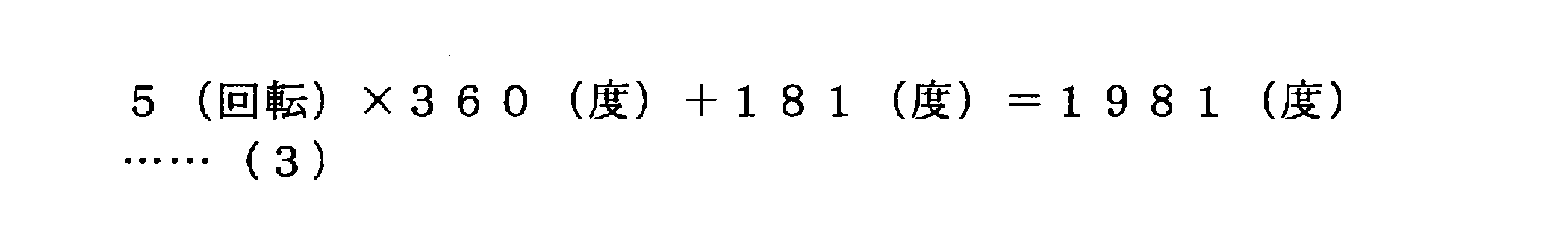

次に、図5及び図6を参照して、本実施形態に係る回転角度検出方法の処理手順について説明する。図5は、本実施形態に係る回転角度検出方法において行われる、入力軸の誤差を考慮した入力軸の累積動作角度の算出処理について説明するための説明図である。図6は、本実施形態に係る回転角度検出方法の処理手順の一例を示すフロー図である。


図1に示すように、本実施形態に係るアクチュエータ300は、その入力軸及び出力軸の双方にエンコーダ330、340を備える。本実施形態では、このような構成を利用して、アクチュエータ300の故障を検出することができる。

本実施形態に係るアクチュエータ300は、医療用ロボットアーム装置の関節部を駆動するアクチュエータとして好適に適用可能である。以下では、まず、医療用ロボットアーム装置のアクチュエータに求められる要件について説明する。次に、それらの要件を満足するかどうかといった観点から、一般的な公知のアクチュエータと、本実施形態に係るアクチュエータ300との比較を行う。
構成(A)は、入力軸にモータ駆動用ホールセンサが設けられ、出力軸に絶対角度エンコーダが設けられる構成である。当該構成(A)は、一般的なアクチュエータにおいてに広く用いられている構成である。モータ駆動用ホールセンサは、ブラシレスモータを駆動するために設けられ、ブラシレスモータの回転子の回転を検出する機能を有する。ただし、エンコーダのように、回転子(又は入力軸)の回転角度を0(度)~360(度)の数値として検出するものではない。一方、構成(A)では、絶対角度エンコーダにより、出力軸の回転角度が検出される。
構成(B)は、入力軸にモータ駆動用ホールセンサが設けられ、出力軸にパルス型エンコーダが設けられる構成である。入力軸にモータ駆動用ホールセンサが設けられる点は、上記構成(A)と同様である。一方、出力軸に設けられるパルス型エンコーダは、放射状にスリットが形成された円板を回転させ、当該円板に光(レーザ等)を照射して、スリットを通過した光を検出することにより、当該円板の回転角度を回転軸の回転角度として検出するものである。パルス型エンコーダは、円板の所定の位置を基準位置として、当該基準位置からの相対的な回転角度が検出される、相対角度エンコーダの一種である。
構成(C)は、入力軸にモータ駆動用ホールセンサ及びパルス型エンコーダが設けられ、出力軸にはエンコーダが設けられない構成である。このように、入力軸にエンコーダを設けることにより、減速比を介している分、出力軸の回転角度を高精度に(高分解能に)検出することが可能となる。従って、構成(C)では、「回転角度の検出要件」はある程度満たされていると言える。
構成(D)は、入力軸に絶対角度エンコーダが設けられ、出力軸にはエンコーダが設けられない構成である。構成(D)では、絶対角度エンコーダがモータ駆動用ホールセンサの役割を兼ねることができる。また、構成(C)と同様に、入力軸にエンコーダが設けられることにより、減速比を介している分、出力軸の回転角度を高精度に(高分解能に)検出することが可能となる。従って、構成(D)では、「回転角度の検出要件」はある程度満たされていると言える。
構成(E)は、入力軸に絶対角度エンコーダ及びギア式回転カウンタが設けられ、出力軸にはエンコーダが設けられない構成である。構成(E)は、構成(D)に対して、入力軸にギア式回転カウンタが追加されたものに対応している。構成(E)では、構成(D)と同様に、絶対角度エンコーダがモータ駆動用ホールセンサの役割を兼ねることができる。また、構成(D)と同様に、入力軸にエンコーダが設けられることにより、減速比を介している分、出力軸の回転角度を高精度に(高分解能に)検出することが可能となる。従って、構成(E)では、「回転角度の検出要件」はある程度満たされていると言える。
上述したように、本実施形態に係るアクチュエータ300は、医療用ロボットアーム装置の関節部に対して好適に適用可能である。以下では、本実施形態に係るアクチュエータ300の一適用例として、当該アクチュエータ300が適用され得るロボットアーム装置の駆動を制御するための、ロボットアーム制御システムの構成や、ロボットアーム制御方法の処理手順について説明する。
まず、本開示をより明確なものとするために、本発明者らが以下に説明する実施形態に想到するに至った背景について説明する。
以下では、本開示の一実施形態に係るロボットアーム制御システムについて説明する。本実施形態に係るロボットアーム制御システムにおいては、ロボットアーム装置に設けられる複数の関節部の駆動を、一般化逆動力学を用いた全身協調制御により制御する。更に、外乱の影響を補正することにより指令値に対する理想的な応答を実現する理想関節制御を当該関節部の駆動制御に適用する。
まず、図8を参照して、本開示の一実施形態に係るロボットアーム装置の概略構成について説明する。図8は、本開示の一実施形態に係るロボットアーム装置の外観を示す概略図である。
次に、本実施形態におけるロボットアーム装置400の全身協調制御に用いられる一般化逆動力学の概要について説明する。
多リンク構造体の各関節部におけるある物理量によって構成されるベクトルを一般化変数qと呼ぶ(関節値q又は関節空間qとも呼称する。)。操作空間xは、一般化変数qの時間微分値とヤコビアンJとを用いて、以下の数式(11)で定義される。


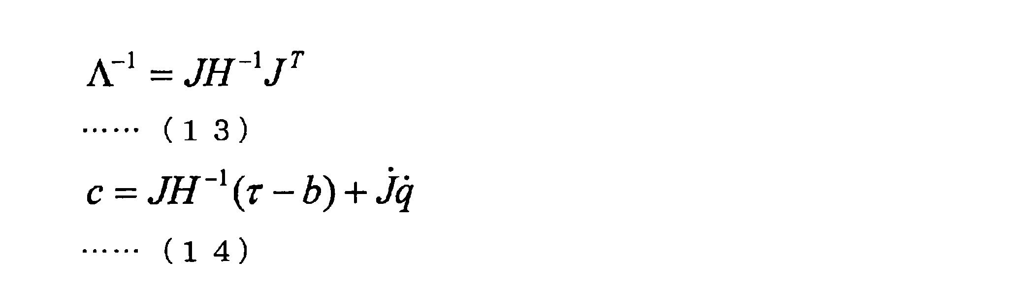
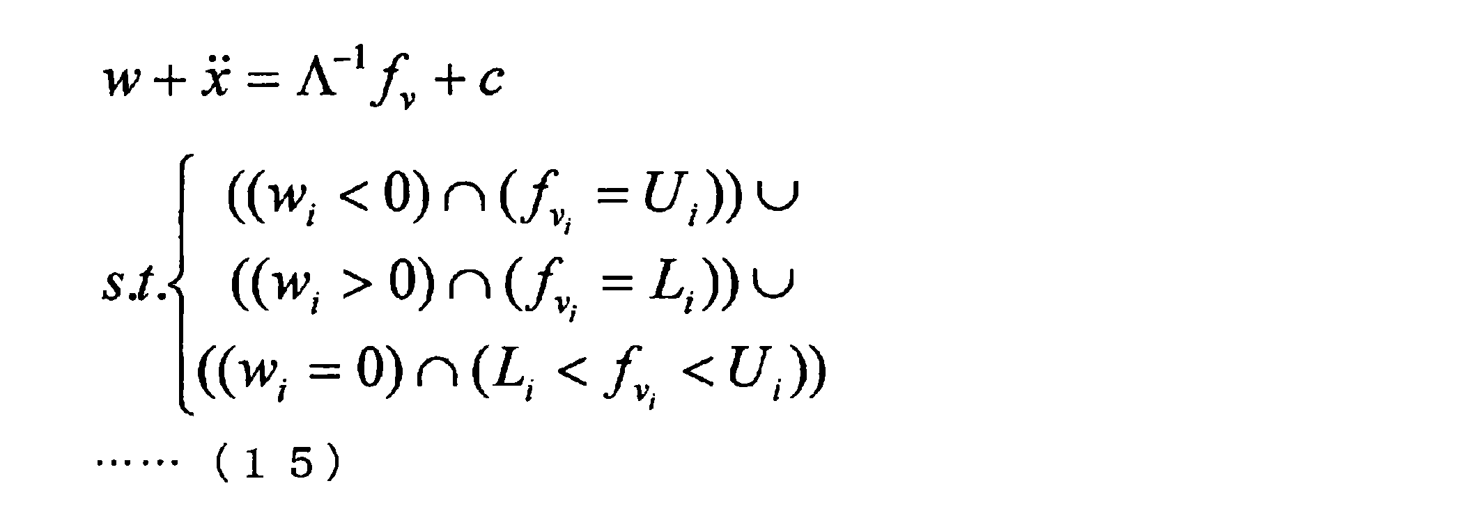
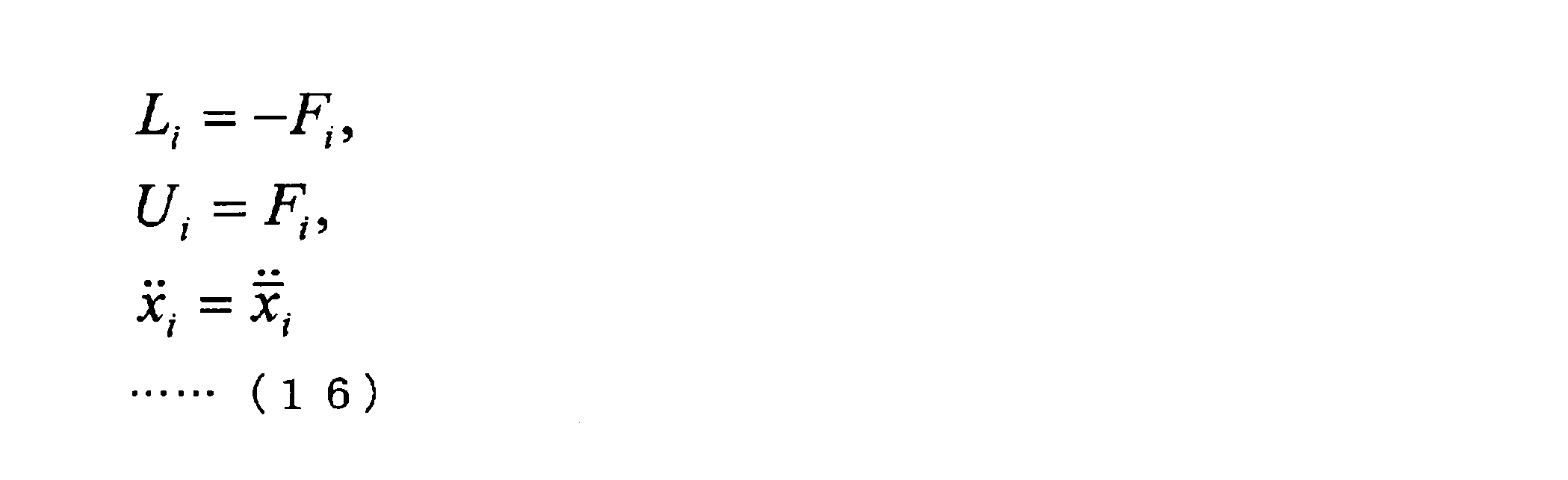
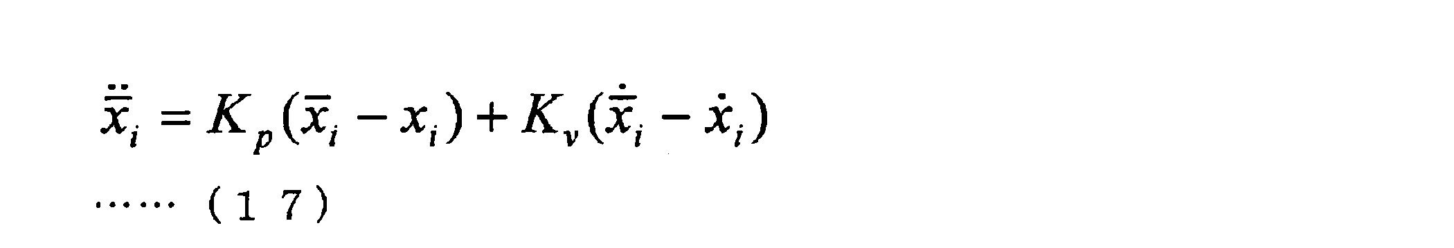
一般化逆動力学の第2段階である実在力算出処理では、上記(2-2-1.仮想力決定プロセス)で得られた仮想力fvを、実在の関節力と外力で置換する処理を行う。仮想力による一般化力τv=Jv Tfvを関節部に生じる発生トルクτaと外力feとで実現するための条件は、下記数式(18)で表現される。


次に、本実施形態に係る理想関節制御について説明する。各関節部421a~421fの運動は、下記数式(22)の二次遅れ系の運動方程式によってモデル化される。
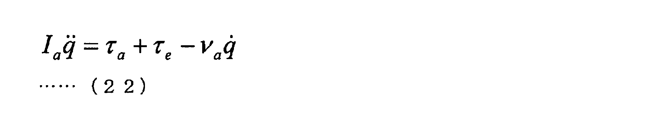
次に、上記(6-2-2.一般化逆動力学について)及び上記(6-2-3.理想関節制御について)で説明した全身協調制御や理想関節制御がロボットアーム装置の駆動制御に適用された、本実施形態に係るロボットアーム制御システムの構成について説明する。
次に、本実施形態に係る運動目的の具体例について説明する。上記(6-2-4.ロボットアーム制御システムの構成)で説明したように、本実施形態においては、全身協調制御によって各種の運動目的が実現される。ここでは、本実施形態に係る運動目的の具体例として、パワーアシスト動作と、ピボット動作について説明する。なお、以下の運動目的の具体例についての説明では、図11に示す機能ブロック図における参照番号を用いて、本実施形態に係るロボットアーム制御システムの構成部材を表す。
次に、図15を参照して、本開示の一実施形態に係るロボットアーム制御方法の処理手順について説明する。図15は、本開示の一実施形態に係るロボットアーム制御方法の処理手順を示すフロー図である。なお、以下では、図11に示すロボットアーム制御システム1の構成によって本実施形態に係るロボットアーム制御方法が実現される場合を例に挙げて説明を行う。従って、本実施形態に係るロボットアーム制御方法は医療用ロボットアーム制御方法であると言える。なお、以下の本実施形態に係るロボットアーム制御方法の処理手順についての説明において、図11に示すロボットアーム制御システム1の各構成の機能については、上記(6-2-4.ロボットアーム制御システムの構成)で既に説明しているため、詳細な説明は省略する。
次に、図16を参照しながら、図11に示す、本実施形態に係るロボットアーム装置10及び制御装置20のハードウェア構成について、詳細に説明する。図16は、本開示の一実施形態に係るロボットアーム装置10及び制御装置20のハードウェア構成の一構成例を示す機能ブロック図である。
以上説明したように、本実施形態においては、以下の効果を得ることができる。
以上、添付図面を参照しながら本開示の好適な実施形態について詳細に説明したが、本開示の技術的範囲はかかる例に限定されない。本開示の技術分野における通常の知識を有する者であれば、特許請求の範囲に記載された技術的思想の範疇内において、各種の変更例または修正例に想到し得ることは明らかであり、これらについても、当然に本開示の技術的範囲に属するものと了解される。
(1)モータの回転軸に連結された入力軸の回転速度を、所定の減速比で減速させ出力軸に伝達する減速機と、前記入力軸の回転角度を検出する第1の絶対角度エンコーダと、前記出力軸の回転角度を検出する第2の絶対角度エンコーダと、を備える、アクチュエータ。
(2)前記第1の絶対角度エンコーダによって検出された前記入力軸の回転角度に基づいて、前記出力軸の回転角度が検出される、前記(1)に記載のアクチュエータ。
(3)前記第2の絶対角度エンコーダによって検出された前記出力軸の回転角度に基づいて、前記出力軸の累積回転数が算出され、前記累積回転数から算出される前記入力軸の累積回転角度に、前記第1の絶対角度エンコーダによって検出された前記入力軸の回転角度を加えることにより、前記出力軸の回転角度が検出される、前記(1)又は(2)に記載のアクチュエータ。
(4)前記第2の絶対角度エンコーダによる前記出力軸の回転角度の検出値から推定される前記入力軸の回転角度に基づいて、前記入力軸の累積回転数が補正される、前記(3)に記載のアクチュエータ。
(5)前記第2の絶対角度エンコーダの回転角度の検出精度は、前記減速機の減速比に応じた、前記入力軸の一回転分に対応する前記出力軸の回転角度未満である、前記(3)に記載のアクチュエータ。
(6)前記入力軸の回転数を保持するカウンタ、を更に備え、前記カウンタの値に基づいて算出される前記入力軸の累積回転角度に、前記第1の絶対角度エンコーダによって検出された前記入力軸の回転角度を加えることにより、前記出力軸の回転角度が検出される、前記(1)又は(2)に記載のアクチュエータ。
(7)前記第1の絶対角度エンコーダによる前記入力軸の回転角度の検出値と、前記第2の絶対角度エンコーダによる前記出力軸の回転角度の検出値と、の関係性に基づいて、前記アクチュエータの故障が検出される、前記(1)~(6)のいずれか1項に記載のアクチュエータ。
(8)前記第1の絶対角度エンコーダによる前記入力軸の回転角度の検出値及び前記第2の絶対角度エンコーダによる前記出力軸の回転角度の検出値の時間変化に更に基づいて、前記モータ、前記減速機、前記第1の絶対角度エンコーダ及び前記第2の絶対角度エンコーダの少なくともいずれかの故障が出される、前記(7)に記載のアクチュエータ。
(9)前記モータはブラシレスモータであり、前記第1の絶対角度エンコーダは、前記モータの回転子の回転を検出するセンサとしても機能する、前記(1)~(8)のいずれか1項に記載のアクチュエータ。
(10)前記第1の絶対角度エンコーダ及び前記第2の絶対角度エンコーダは、磁石の回転に伴う磁界の変化を、複数の磁気センサにより所定の位相だけずれた状態で検出することにより、当該磁石の回転角度を検出する、磁気式エンコーダである、前記(1)~(9)のいずれか1項に記載のアクチュエータ。
(11)複数のリンクが複数の関節部によって連結されて構成されるアーム部と、前記関節部の状態に基づいて、少なくとも一つの前記関節部に設けられるアクチュエータの駆動を制御する駆動制御部と、を備え、前記アクチュエータは、モータの回転軸に連結された入力軸の回転速度を、所定の減速比で減速させ出力軸に伝達する減速機と、前記入力軸の回転角度を検出する第1の絶対角度エンコーダと、前記出力軸の回転角度を検出する第2の絶対角度エンコーダと、を有する、ロボットアーム装置。
(12)前記第1の絶対角度エンコーダによって検出された前記入力軸の回転角度に基づいて、前記出力軸の回転角度が検出される、前記(11)に記載のロボットアーム装置。
(13)前記第2の絶対角度エンコーダによって検出された前記出力軸の回転角度に基づいて、前記出力軸の累積回転数が算出され、前記累積回転数から算出される前記入力軸の累積回転角度に、前記第1の絶対角度エンコーダによって検出された前記入力軸の回転角度を加えることにより、前記出力軸の回転角度が検出される、前記(11)又は(12)に記載のロボットアーム装置。
(14)前記第2の絶対角度エンコーダによる前記出力軸の回転角度の検出値から推定される前記入力軸の回転角度に基づいて、前記入力軸の累積回転数が補正される、前記(13)に記載のロボットアーム装置。
(15)前記第2の絶対角度エンコーダの回転角度の検出精度は、前記減速機の減速比に応じた、前記入力軸の一回転分に対応する前記出力軸の回転角度未満である、前記(13)に記載のロボットアーム装置。
(16)前記入力軸の回転数を保持するカウンタ、を更に備え、前記カウンタの値に基づいて算出される前記入力軸の累積回転角度に、前記第1の絶対角度エンコーダによって検出された前記入力軸の回転角度を加えることにより、前記出力軸の回転角度が検出される、前記(11)又は(12)に記載のロボットアーム装置。
(17)前記第1の絶対角度エンコーダによる前記入力軸の回転角度の検出値と、前記第2の絶対角度エンコーダによる前記出力軸の回転角度の検出値と、の関係性に基づいて、前記アクチュエータの故障が検出される、前記(11)~(16)のいずれか1項に記載のロボットアーム装置。
(18)前記第1の絶対角度エンコーダによる前記入力軸の回転角度の検出値及び前記第2の絶対角度エンコーダによる前記出力軸の回転角度の検出値の時間変化に更に基づいて、前記モータ、前記減速機、前記第1の絶対角度エンコーダ及び前記第2の絶対角度エンコーダの少なくともいずれかの故障が出される、前記(17)に記載のロボットアーム装置。
(19)前記モータはブラシレスモータであり、前記第1の絶対角度エンコーダは、前記モータを駆動するために前記モータの回転子の回転を検出するセンサとしても機能する、前記(11)~(18)のいずれか1項に記載のロボットアーム装置。
(20)前記第1の絶対角度エンコーダ及び前記第2の絶対角度エンコーダは、磁石の回転に伴う磁界の変化を、複数の磁気センサにより所定の位相だけずれた状態で検出することにより、当該磁石の回転角度を検出する、磁気式エンコーダである、前記(11)~(19)のいずれか1項に記載のロボットアーム装置。
(21)前記アーム部には、所定の処置を行う器具が装着される装着部が設けられる、前記(11)~(20)のいずれか1項に記載のロボットアーム装置。
(22)前記器具は医療用器具である、前記(21)に記載のロボットアーム装置。
3 回転角度検出システム
10 ロボットアーム装置
20 制御装置
30 表示装置
110 アーム制御部
111 駆動制御部
120 アーム部
130 関節部
131 関節駆動部
132 回転角度検出部
133 トルク検出部
140 撮像部
210 入力部
220 記憶部
230 制御部
240 全身協調制御部
241 アーム状態取得部
242 演算条件設定部
243 仮想力算出部
244 実在力算出部
250 理想関節制御部
251 外乱推定部
252 指令値算出部
300 アクチュエータ
310 モータ(ブラシレスモータ)
320 減速機
330 エンコーダ(入力軸エンコーダ、絶対角度エンコーダ)
340 エンコーダ(出力軸エンコーダ、絶対角度エンコーダ)
350 出力軸
360 ハウジング
370 制御部
371 出力軸角度情報取得部
372 モータ累積回転角度算出部
373 入力軸角度情報取得部
374 入力軸累積動作角度算出部
375 出力軸角度算出部
Claims (22)
- モータの回転軸に連結された入力軸の回転速度を、所定の減速比で減速させ出力軸に伝達する減速機と、
前記入力軸の回転角度を検出する第1の絶対角度エンコーダと、
前記出力軸の回転角度を検出する第2の絶対角度エンコーダと、
を備える、アクチュエータ。 - 前記第1の絶対角度エンコーダによって検出された前記入力軸の回転角度に基づいて、前記出力軸の回転角度が検出される、
請求項1に記載のアクチュエータ。 - 前記第2の絶対角度エンコーダによって検出された前記出力軸の回転角度に基づいて、前記入力軸の累積回転数が算出され、
前記累積回転数から算出される前記入力軸の累積回転角度に、前記第1の絶対角度エンコーダによって検出された前記入力軸の回転角度を加えることにより、前記出力軸の回転角度が検出される、
請求項1に記載のアクチュエータ。 - 前記第2の絶対角度エンコーダによる前記出力軸の回転角度の検出値から推定される前記入力軸の回転角度に基づいて、前記入力軸の累積回転数が補正される、
請求項3に記載のアクチュエータ。 - 前記第2の絶対角度エンコーダの回転角度の検出精度は、前記減速機の減速比に応じた、前記入力軸の一回転分に対応する前記出力軸の回転角度未満である、
請求項3に記載のアクチュエータ。 - 前記入力軸の回転数を保持するカウンタ、を更に備え、
前記カウンタの値に基づいて算出される前記入力軸の累積回転角度に、前記第1の絶対角度エンコーダによって検出された前記入力軸の回転角度を加えることにより、前記出力軸の回転角度が検出される、
請求項1に記載のアクチュエータ。 - 前記第1の絶対角度エンコーダによる前記入力軸の回転角度の検出値と、前記第2の絶対角度エンコーダによる前記出力軸の回転角度の検出値と、の関係性に基づいて、前記アクチュエータの故障が検出される、
請求項1に記載のアクチュエータ。 - 前記第1の絶対角度エンコーダによる前記入力軸の回転角度の検出値及び前記第2の絶対角度エンコーダによる前記出力軸の回転角度の検出値の時間変化に更に基づいて、前記モータ、前記減速機、前記第1の絶対角度エンコーダ及び前記第2の絶対角度エンコーダの少なくともいずれかの故障が出される、
請求項7に記載のアクチュエータ。 - 前記モータはブラシレスモータであり、
前記第1の絶対角度エンコーダは、前記モータの回転子の回転を検出するセンサとしても機能する、
請求項1に記載のアクチュエータ。 - 前記第1の絶対角度エンコーダ及び前記第2の絶対角度エンコーダは、磁石の回転に伴う磁界の変化を、複数の磁気センサにより所定の位相だけずれた状態で検出することにより、当該磁石の回転角度を検出する、磁気式エンコーダである、
請求項1に記載のアクチュエータ。 - 複数のリンクが関節部によって連結されて構成されるアーム部と、
前記関節部の状態に基づいて、少なくとも一つの前記関節部に設けられるアクチュエータの駆動を制御する駆動制御部と、
を備え、
前記アクチュエータは、
モータの回転軸に連結された入力軸の回転速度を、所定の減速比で減速させ出力軸に伝達する減速機と、
前記入力軸の回転角度を検出する第1の絶対角度エンコーダと、
前記出力軸の回転角度を検出する第2の絶対角度エンコーダと、
を有する、ロボットアーム装置。 - 前記第1の絶対角度エンコーダによって検出された前記入力軸の回転角度に基づいて、前記出力軸の回転角度が検出される、
請求項11に記載のロボットアーム装置。 - 前記第2の絶対角度エンコーダによって検出された前記出力軸の回転角度に基づいて、前記入力軸の累積回転数が算出され、
前記累積回転数から算出される前記入力軸の累積回転角度に、前記第1の絶対角度エンコーダによって検出された前記入力軸の回転角度を加えることにより、前記出力軸の回転角度が検出される、
請求項11に記載のロボットアーム装置。 - 前記第2の絶対角度エンコーダによる前記出力軸の回転角度の検出値から推定される前記入力軸の回転角度に基づいて、前記入力軸の累積回転数が補正される、
請求項13に記載のロボットアーム装置。 - 前記第2の絶対角度エンコーダの回転角度の検出精度は、前記減速機の減速比に応じた、前記入力軸の一回転分に対応する前記出力軸の回転角度未満である、
請求項13に記載のロボットアーム装置。 - 前記入力軸の回転数を保持するカウンタ、を更に備え、
前記カウンタの値に基づいて算出される前記入力軸の累積回転角度に、前記第1の絶対角度エンコーダによって検出された前記入力軸の回転角度を加えることにより、前記出力軸の回転角度が検出される、
請求項11に記載のロボットアーム装置。 - 前記第1の絶対角度エンコーダによる前記入力軸の回転角度の検出値と、前記第2の絶対角度エンコーダによる前記出力軸の回転角度の検出値と、の関係性に基づいて、前記アクチュエータの故障が検出される、
請求項11に記載のロボットアーム装置。 - 前記第1の絶対角度エンコーダによる前記入力軸の回転角度の検出値及び前記第2の絶対角度エンコーダによる前記出力軸の回転角度の検出値の時間変化に更に基づいて、前記モータ、前記減速機、前記第1の絶対角度エンコーダ及び前記第2の絶対角度エンコーダの少なくともいずれかの故障が出される、
請求項17に記載のロボットアーム装置。 - 前記モータはブラシレスモータであり、
前記第1の絶対角度エンコーダは、前記モータの回転子の回転を検出するセンサとしても機能する、
請求項11に記載のロボットアーム装置。 - 前記第1の絶対角度エンコーダ及び前記第2の絶対角度エンコーダは、磁石の回転に伴う磁界の変化を、複数の磁気センサにより所定の位相だけずれた状態で検出することにより、当該磁石の回転角度を検出する、磁気式エンコーダである、
請求項11に記載のロボットアーム装置。 - 前記アーム部には、所定の処置を行う器具が装着される装着部が設けられる、
請求項11に記載のロボットアーム装置。 - 前記器具は医療用器具である、
請求項21に記載のロボットアーム装置。
Priority Applications (5)
| Application Number | Priority Date | Filing Date | Title |
|---|---|---|---|
| US15/121,602 US9966816B2 (en) | 2014-03-06 | 2015-02-19 | Actuator and robot arm apparatus |
| CN201580011276.2A CN106063090B (zh) | 2014-03-06 | 2015-02-19 | 传动装置及机器人手臂装置 |
| JP2016506422A JP6496937B2 (ja) | 2014-03-06 | 2015-02-19 | アクチュエータ及びロボットアーム装置 |
| EP15757822.0A EP3109980A4 (en) | 2014-03-06 | 2015-02-19 | Actuator and robot arm apparatus |
| US15/954,737 US10505428B2 (en) | 2014-03-06 | 2018-04-17 | Actuator and robot arm apparatus |
Applications Claiming Priority (2)
| Application Number | Priority Date | Filing Date | Title |
|---|---|---|---|
| JP2014-044134 | 2014-03-06 | ||
| JP2014044134 | 2014-03-06 |
Related Child Applications (2)
| Application Number | Title | Priority Date | Filing Date |
|---|---|---|---|
| US15/121,602 A-371-Of-International US9966816B2 (en) | 2014-03-06 | 2015-02-19 | Actuator and robot arm apparatus |
| US15/954,737 Continuation US10505428B2 (en) | 2014-03-06 | 2018-04-17 | Actuator and robot arm apparatus |
Publications (1)
| Publication Number | Publication Date |
|---|---|
| WO2015133291A1 true WO2015133291A1 (ja) | 2015-09-11 |
Family
ID=54055101
Family Applications (1)
| Application Number | Title | Priority Date | Filing Date |
|---|---|---|---|
| PCT/JP2015/054675 WO2015133291A1 (ja) | 2014-03-06 | 2015-02-19 | アクチュエータ及びロボットアーム装置 |
Country Status (5)
| Country | Link |
|---|---|
| US (2) | US9966816B2 (ja) |
| EP (1) | EP3109980A4 (ja) |
| JP (1) | JP6496937B2 (ja) |
| CN (1) | CN106063090B (ja) |
| WO (1) | WO2015133291A1 (ja) |
Cited By (11)
| Publication number | Priority date | Publication date | Assignee | Title |
|---|---|---|---|---|
| CN107229019A (zh) * | 2016-03-23 | 2017-10-03 | 南京德朔实业有限公司 | 电动工具系统 |
| WO2017169082A1 (ja) * | 2016-03-29 | 2017-10-05 | ソニー株式会社 | 制御装置及び制御方法 |
| JP2018175863A (ja) * | 2017-04-20 | 2018-11-15 | リバーフィールド株式会社 | アーム装置 |
| CN109874392A (zh) * | 2015-12-18 | 2019-06-11 | 韩国原子力研究院 | 电机控制装置及方法 |
| EP3514923A4 (en) * | 2016-10-27 | 2019-10-16 | SZ DJI Osmo Technology Co., Ltd. | ENGINE, BEARING HEAD AND PHOTOGRAPHY DEVICE |
| JP2019207204A (ja) * | 2018-05-30 | 2019-12-05 | 株式会社デンソー | 回転検出装置、および、これを用いた電動パワーステアリング装置 |
| WO2020066946A1 (ja) * | 2018-09-26 | 2020-04-02 | 日本電産株式会社 | モータ装置 |
| US10637332B2 (en) | 2017-12-06 | 2020-04-28 | Nidec Tosok Corporation | Electric actuator |
| EP3249767B1 (de) * | 2016-04-29 | 2022-01-26 | Lock Antriebstechnik GmbH | Schaltvorrichtung zum schalten eines elektrischen motors |
| JP2022533230A (ja) * | 2019-05-21 | 2022-07-21 | ヴァレオ システム デシュヤージュ | ワイパーモータの回転部品の回転角度位置を検出するための方法、およびワイパーモータ |
| WO2023090204A1 (ja) * | 2021-11-16 | 2023-05-25 | ソニーグループ株式会社 | 制御システム、制御装置及びアクチュエータ |
Families Citing this family (35)
| Publication number | Priority date | Publication date | Assignee | Title |
|---|---|---|---|---|
| GB2540756B (en) | 2015-07-22 | 2021-03-31 | Cmr Surgical Ltd | Gear packaging for robot arms |
| EP3524394B1 (en) | 2015-07-22 | 2024-02-21 | CMR Surgical Limited | Torque sensors |
| GB2541369B (en) | 2015-07-22 | 2021-03-31 | Cmr Surgical Ltd | Drive mechanisms for robot arms |
| FR3042327B1 (fr) * | 2015-10-07 | 2019-08-02 | Guillemot Corporation | Systeme de refroidissement d'un moteur electrique |
| JP6858750B2 (ja) * | 2016-03-28 | 2021-04-14 | ソニー・オリンパスメディカルソリューションズ株式会社 | 医療用観察装置、駆動制御方法、医療用観察システム及び支持アーム装置 |
| DE102016111097A1 (de) * | 2016-06-17 | 2017-12-21 | Knorr-Bremse Systeme für Nutzfahrzeuge GmbH | Sensoranordnung zur Winkelerfassung und Schaltgetriebe |
| CN106981967A (zh) * | 2017-05-09 | 2017-07-25 | 深圳市普渡科技有限公司 | 一种直驱外转子无刷电机及其旋转关节 |
| JP2018202589A (ja) * | 2017-06-09 | 2018-12-27 | セイコーエプソン株式会社 | 制御装置、ロボット、およびロボットシステム |
| JP6915395B2 (ja) * | 2017-06-16 | 2021-08-04 | セイコーエプソン株式会社 | 制御装置、ロボットシステム、テーブル作成方法およびロボット制御方法 |
| CN107160366B (zh) * | 2017-06-20 | 2021-05-04 | 成都黑盒子科技有限公司 | 一种服务型机器人手臂结构及关节处角度校正方法 |
| CN109434279A (zh) * | 2017-09-04 | 2019-03-08 | Hb技术有限公司 | 运用电机编码器信号信息的激光系统 |
| JP6934788B2 (ja) * | 2017-09-19 | 2021-09-15 | ミネベアミツミ株式会社 | 角度検出装置、回転量特定ユニットおよび回転駆動ユニット |
| CN107856057B (zh) * | 2017-11-30 | 2024-03-29 | 深圳市优必选科技有限公司 | 一种连杆机构及机器人 |
| JP7027235B2 (ja) * | 2018-04-16 | 2022-03-01 | 株式会社マキタ | 電動工具 |
| CN108656115B (zh) * | 2018-05-17 | 2021-04-27 | 黄云汉 | 一种关节式机器人的关节减速机的控制方法 |
| JP7234577B2 (ja) * | 2018-10-31 | 2023-03-08 | セイコーエプソン株式会社 | ロボットシステム、ロボット制御方法、及びエンコーダー |
| CN109676635A (zh) * | 2018-12-21 | 2019-04-26 | 江苏集萃智能制造技术研究所有限公司 | 一种用于协作机器人碰撞检测的双编码器 |
| US20200231082A1 (en) * | 2019-01-21 | 2020-07-23 | Kevin Arnold Morran | Remote controlled lighting apparatus |
| CN109760033B (zh) * | 2019-02-01 | 2020-08-14 | 苏州小工匠机器人有限公司 | 机械手装置控制方法及控制系统 |
| WO2020172403A1 (en) | 2019-02-20 | 2020-08-27 | Harmonic Bionics | Actuator for physical therapy |
| JP7172797B2 (ja) * | 2019-03-28 | 2022-11-16 | 株式会社デンソー | 検出ユニット |
| KR102356660B1 (ko) * | 2019-11-01 | 2022-02-07 | 주식회사 뉴로메카 | 다자유도 협동 로봇의 마찰 보상 방법 |
| TWI747079B (zh) * | 2019-11-19 | 2021-11-21 | 財團法人資訊工業策進會 | 機械手臂的定位精度量測系統與方法 |
| CN111106765A (zh) * | 2019-12-30 | 2020-05-05 | 中国科学院长春光学精密机械与物理研究所 | 一种无刷电机驱动系统及方法 |
| CN111216103A (zh) * | 2020-01-07 | 2020-06-02 | 北京可以科技有限公司 | 模块单元位置伺服系统及其控制方法、模块机器人 |
| WO2021211578A1 (en) * | 2020-04-13 | 2021-10-21 | Orangewoodlabs Inc. | System and/or method for error compensation in mechanical transmissions |
| CN111721329B (zh) * | 2020-07-07 | 2021-11-23 | 哈尔滨理工大学 | 一种三霍尔磁电编码器及免反正切计算角度解算方法 |
| CN111761584A (zh) * | 2020-07-17 | 2020-10-13 | 上海布鲁可科技有限公司 | 带参考点的闭环控制系统、方法、运动机器人及介质 |
| CN112117872B (zh) * | 2020-07-24 | 2022-05-06 | 哈尔滨工业大学 | 特种电机、电气设备及车辆 |
| CN112671272B (zh) * | 2020-11-25 | 2023-03-17 | 河北汉光重工有限责任公司 | 一种直流力矩电机启动过程精确控制方法 |
| WO2022146262A1 (en) | 2020-12-31 | 2022-07-07 | Ozyegin Universitesi | An actuator embodiment for use in robot systems |
| TWI772118B (zh) * | 2021-07-21 | 2022-07-21 | 中強光電股份有限公司 | 機器人之關節致動器 |
| US11541530B1 (en) | 2021-09-30 | 2023-01-03 | Harmonic Bionics, Inc. | Compliant mechanism for improving axial load sensing in robotic actuators |
| KR102699519B1 (ko) * | 2021-11-09 | 2024-08-26 | 두산로보틱스 주식회사 | 로봇팔의 중력 보상 구조 및 이를 포함하는 로봇팔 |
| CN114715369B (zh) * | 2022-03-07 | 2022-12-20 | 华中科技大学 | 一种磁性软体机器人的驱动方法及装置 |
Citations (5)
| Publication number | Priority date | Publication date | Assignee | Title |
|---|---|---|---|---|
| JPS6415609A (en) * | 1987-07-10 | 1989-01-19 | Kobe Steel Ltd | Detecting apparatus for rotational angle of industrial robot |
| JP2008148412A (ja) * | 2006-12-07 | 2008-06-26 | Asmo Co Ltd | モータ制御装置 |
| WO2010023896A1 (ja) * | 2008-08-26 | 2010-03-04 | 株式会社ニコン | エンコーダシステム、信号処理方法、及び送信信号生成出力装置 |
| JP2011007658A (ja) * | 2009-06-26 | 2011-01-13 | Nikon Corp | エンコーダおよび信号処理方法 |
| JP2011027719A (ja) * | 2009-06-30 | 2011-02-10 | Ntn Corp | 自動車駆動用モータの回転角度検出装置および回転角度検出装置付き軸受 |
Family Cites Families (7)
| Publication number | Priority date | Publication date | Assignee | Title |
|---|---|---|---|---|
| JP2007078552A (ja) | 2005-09-15 | 2007-03-29 | Ntn Corp | 多回転角度検出装置および多回転角度検出装置付き軸受 |
| JP2008039737A (ja) * | 2006-08-10 | 2008-02-21 | Yaskawa Electric Corp | 多回転量算出方法、バッテリーレス多回転式絶対値エンコーダ装置およびこれを用いた減速機付アクチュエータ |
| WO2008056793A1 (fr) * | 2006-11-10 | 2008-05-15 | The Furukawa Electric Co., Ltd. | Appareil de détermination de l'angle de rotation |
| JP5645423B2 (ja) * | 2010-02-23 | 2014-12-24 | キヤノン株式会社 | 回転駆動装置及びロボットアーム |
| JP5488494B2 (ja) | 2011-02-23 | 2014-05-14 | 株式会社安川電機 | ロボットシステム |
| JP5938954B2 (ja) * | 2012-03-06 | 2016-06-22 | 株式会社ジェイテクト | ロボットのキャリブレーション方法及びキャリブレーション装置 |
| AU2013296278B2 (en) | 2012-08-03 | 2018-06-14 | Stryker Corporation | Systems and methods for robotic surgery |
-
2015
- 2015-02-19 JP JP2016506422A patent/JP6496937B2/ja active Active
- 2015-02-19 EP EP15757822.0A patent/EP3109980A4/en not_active Withdrawn
- 2015-02-19 US US15/121,602 patent/US9966816B2/en active Active
- 2015-02-19 WO PCT/JP2015/054675 patent/WO2015133291A1/ja active Application Filing
- 2015-02-19 CN CN201580011276.2A patent/CN106063090B/zh active Active
-
2018
- 2018-04-17 US US15/954,737 patent/US10505428B2/en active Active
Patent Citations (5)
| Publication number | Priority date | Publication date | Assignee | Title |
|---|---|---|---|---|
| JPS6415609A (en) * | 1987-07-10 | 1989-01-19 | Kobe Steel Ltd | Detecting apparatus for rotational angle of industrial robot |
| JP2008148412A (ja) * | 2006-12-07 | 2008-06-26 | Asmo Co Ltd | モータ制御装置 |
| WO2010023896A1 (ja) * | 2008-08-26 | 2010-03-04 | 株式会社ニコン | エンコーダシステム、信号処理方法、及び送信信号生成出力装置 |
| JP2011007658A (ja) * | 2009-06-26 | 2011-01-13 | Nikon Corp | エンコーダおよび信号処理方法 |
| JP2011027719A (ja) * | 2009-06-30 | 2011-02-10 | Ntn Corp | 自動車駆動用モータの回転角度検出装置および回転角度検出装置付き軸受 |
Non-Patent Citations (1)
| Title |
|---|
| See also references of EP3109980A4 * |
Cited By (16)
| Publication number | Priority date | Publication date | Assignee | Title |
|---|---|---|---|---|
| CN109874392B (zh) * | 2015-12-18 | 2022-05-27 | 韩国原子力研究院 | 电机控制装置及方法 |
| CN109874392A (zh) * | 2015-12-18 | 2019-06-11 | 韩国原子力研究院 | 电机控制装置及方法 |
| CN107229019A (zh) * | 2016-03-23 | 2017-10-03 | 南京德朔实业有限公司 | 电动工具系统 |
| WO2017169082A1 (ja) * | 2016-03-29 | 2017-10-05 | ソニー株式会社 | 制御装置及び制御方法 |
| US11305422B2 (en) | 2016-03-29 | 2022-04-19 | Sony Corporation | Control apparatus and control method |
| EP3249767B1 (de) * | 2016-04-29 | 2022-01-26 | Lock Antriebstechnik GmbH | Schaltvorrichtung zum schalten eines elektrischen motors |
| US10655776B2 (en) | 2016-10-27 | 2020-05-19 | Sz Dji Osmo Technology Co., Ltd. | Gimbal and camera appartus |
| EP3514923A4 (en) * | 2016-10-27 | 2019-10-16 | SZ DJI Osmo Technology Co., Ltd. | ENGINE, BEARING HEAD AND PHOTOGRAPHY DEVICE |
| WO2019193775A1 (ja) * | 2017-04-20 | 2019-10-10 | リバーフィールド株式会社 | アーム装置 |
| JP2018175863A (ja) * | 2017-04-20 | 2018-11-15 | リバーフィールド株式会社 | アーム装置 |
| US10637332B2 (en) | 2017-12-06 | 2020-04-28 | Nidec Tosok Corporation | Electric actuator |
| JP2019207204A (ja) * | 2018-05-30 | 2019-12-05 | 株式会社デンソー | 回転検出装置、および、これを用いた電動パワーステアリング装置 |
| WO2020066946A1 (ja) * | 2018-09-26 | 2020-04-02 | 日本電産株式会社 | モータ装置 |
| JP2022533230A (ja) * | 2019-05-21 | 2022-07-21 | ヴァレオ システム デシュヤージュ | ワイパーモータの回転部品の回転角度位置を検出するための方法、およびワイパーモータ |
| US11962260B2 (en) | 2019-05-21 | 2024-04-16 | Valeo Systemes D'essuyage | Method for detecting the rotary angle positions of rotating parts of a wiper motor, and wiper motor |
| WO2023090204A1 (ja) * | 2021-11-16 | 2023-05-25 | ソニーグループ株式会社 | 制御システム、制御装置及びアクチュエータ |
Also Published As
| Publication number | Publication date |
|---|---|
| CN106063090B (zh) | 2019-08-13 |
| US20180241283A1 (en) | 2018-08-23 |
| EP3109980A1 (en) | 2016-12-28 |
| US20160365771A1 (en) | 2016-12-15 |
| JP6496937B2 (ja) | 2019-04-10 |
| CN106063090A (zh) | 2016-10-26 |
| US9966816B2 (en) | 2018-05-08 |
| EP3109980A4 (en) | 2018-04-18 |
| US10505428B2 (en) | 2019-12-10 |
| JPWO2015133291A1 (ja) | 2017-04-06 |
Similar Documents
| Publication | Publication Date | Title |
|---|---|---|
| JP6496937B2 (ja) | アクチュエータ及びロボットアーム装置 | |
| JP6773165B2 (ja) | 医療用支持アーム装置、医療用支持アーム制御方法及びプログラム | |
| JP6921762B2 (ja) | 手術用顕微鏡装置、手術用顕微鏡装置制御システム、手術用顕微鏡装置制御方法及びプログラム | |
| JP6614130B2 (ja) | 手術用ロボットアーム装置、手術用ロボットアーム制御方法及びプログラム | |
| JP6555248B2 (ja) | 医療用アーム装置、キャリブレーション方法及びプログラム | |
| JP6586079B2 (ja) | アーム装置、及びプログラム | |
| WO2015137040A1 (ja) | ロボットアーム装置、ロボットアーム制御方法及びプログラム | |
| WO2017169096A1 (ja) | 医療用支持アームの制御装置、医療用支持アーム装置の制御方法及び医療用システム | |
| WO2018221035A1 (ja) | 医療用支持アームシステム、医療用支持アームの制御方法、および医療用支持アームの制御装置 | |
| WO2015137140A1 (ja) | ロボットアームの制御装置、ロボットアームの制御方法及びプログラム |
Legal Events
| Date | Code | Title | Description |
|---|---|---|---|
| 121 | Ep: the epo has been informed by wipo that ep was designated in this application |
Ref document number: 15757822 Country of ref document: EP Kind code of ref document: A1 |
|
| ENP | Entry into the national phase |
Ref document number: 2016506422 Country of ref document: JP Kind code of ref document: A |
|
| REEP | Request for entry into the european phase |
Ref document number: 2015757822 Country of ref document: EP |
|
| WWE | Wipo information: entry into national phase |
Ref document number: 2015757822 Country of ref document: EP |
|
| WWE | Wipo information: entry into national phase |
Ref document number: 15121602 Country of ref document: US |
|
| NENP | Non-entry into the national phase |
Ref country code: DE |