WO2015133173A1 - 冷蔵庫 - Google Patents
冷蔵庫 Download PDFInfo
- Publication number
- WO2015133173A1 WO2015133173A1 PCT/JP2015/050864 JP2015050864W WO2015133173A1 WO 2015133173 A1 WO2015133173 A1 WO 2015133173A1 JP 2015050864 W JP2015050864 W JP 2015050864W WO 2015133173 A1 WO2015133173 A1 WO 2015133173A1
- Authority
- WO
- WIPO (PCT)
- Prior art keywords
- temperature
- refrigerator
- compressor
- compartment
- outside air
- Prior art date
- Legal status (The legal status is an assumption and is not a legal conclusion. Google has not performed a legal analysis and makes no representation as to the accuracy of the status listed.)
- Ceased
Links
Images




Classifications
-
- F—MECHANICAL ENGINEERING; LIGHTING; HEATING; WEAPONS; BLASTING
- F25—REFRIGERATION OR COOLING; COMBINED HEATING AND REFRIGERATION SYSTEMS; HEAT PUMP SYSTEMS; MANUFACTURE OR STORAGE OF ICE; LIQUEFACTION SOLIDIFICATION OF GASES
- F25D—REFRIGERATORS; COLD ROOMS; ICE-BOXES; COOLING OR FREEZING APPARATUS NOT OTHERWISE PROVIDED FOR
- F25D17/00—Arrangements for circulating cooling fluids; Arrangements for circulating gas, e.g. air, within refrigerated spaces
- F25D17/04—Arrangements for circulating cooling fluids; Arrangements for circulating gas, e.g. air, within refrigerated spaces for circulating air, e.g. by convection
- F25D17/06—Arrangements for circulating cooling fluids; Arrangements for circulating gas, e.g. air, within refrigerated spaces for circulating air, e.g. by convection by forced circulation
- F25D17/062—Arrangements for circulating cooling fluids; Arrangements for circulating gas, e.g. air, within refrigerated spaces for circulating air, e.g. by convection by forced circulation in household refrigerators
- F25D17/065—Arrangements for circulating cooling fluids; Arrangements for circulating gas, e.g. air, within refrigerated spaces for circulating air, e.g. by convection by forced circulation in household refrigerators with compartments at different temperatures
-
- F—MECHANICAL ENGINEERING; LIGHTING; HEATING; WEAPONS; BLASTING
- F25—REFRIGERATION OR COOLING; COMBINED HEATING AND REFRIGERATION SYSTEMS; HEAT PUMP SYSTEMS; MANUFACTURE OR STORAGE OF ICE; LIQUEFACTION SOLIDIFICATION OF GASES
- F25B—REFRIGERATION MACHINES, PLANTS OR SYSTEMS; COMBINED HEATING AND REFRIGERATION SYSTEMS; HEAT PUMP SYSTEMS
- F25B2600/00—Control issues
- F25B2600/02—Compressor control
- F25B2600/025—Compressor control by controlling speed
- F25B2600/0251—Compressor control by controlling speed with on-off operation
-
- F—MECHANICAL ENGINEERING; LIGHTING; HEATING; WEAPONS; BLASTING
- F25—REFRIGERATION OR COOLING; COMBINED HEATING AND REFRIGERATION SYSTEMS; HEAT PUMP SYSTEMS; MANUFACTURE OR STORAGE OF ICE; LIQUEFACTION SOLIDIFICATION OF GASES
- F25B—REFRIGERATION MACHINES, PLANTS OR SYSTEMS; COMBINED HEATING AND REFRIGERATION SYSTEMS; HEAT PUMP SYSTEMS
- F25B2600/00—Control issues
- F25B2600/11—Fan speed control
- F25B2600/112—Fan speed control of evaporator fans
-
- F—MECHANICAL ENGINEERING; LIGHTING; HEATING; WEAPONS; BLASTING
- F25—REFRIGERATION OR COOLING; COMBINED HEATING AND REFRIGERATION SYSTEMS; HEAT PUMP SYSTEMS; MANUFACTURE OR STORAGE OF ICE; LIQUEFACTION SOLIDIFICATION OF GASES
- F25D—REFRIGERATORS; COLD ROOMS; ICE-BOXES; COOLING OR FREEZING APPARATUS NOT OTHERWISE PROVIDED FOR
- F25D2700/00—Means for sensing or measuring; Sensors therefor
- F25D2700/12—Sensors measuring the inside temperature
-
- F—MECHANICAL ENGINEERING; LIGHTING; HEATING; WEAPONS; BLASTING
- F25—REFRIGERATION OR COOLING; COMBINED HEATING AND REFRIGERATION SYSTEMS; HEAT PUMP SYSTEMS; MANUFACTURE OR STORAGE OF ICE; LIQUEFACTION SOLIDIFICATION OF GASES
- F25D—REFRIGERATORS; COLD ROOMS; ICE-BOXES; COOLING OR FREEZING APPARATUS NOT OTHERWISE PROVIDED FOR
- F25D2700/00—Means for sensing or measuring; Sensors therefor
- F25D2700/14—Sensors measuring the temperature outside the refrigerator or freezer
Definitions
- the present invention relates to a refrigerator.
- Patent Document 1 A conventional refrigerator is disclosed in Patent Document 1.
- This refrigerator is provided with a shutter for increasing / decreasing the opening area of a duct in a duct for circulating cold air in a refrigerator compartment. Then, by opening and closing the shutter, the amount of cool air circulation in the refrigerator compartment is increased or decreased to control the operation time of the compressor, thereby adjusting the temperature of the freezer compartment.
- the cheap refrigerator which does not mount the temperature sensor for freezers, or the damper for temperature control of a refrigerator compartment is provided.
- the user has to manually open and close the shutter according to changes in the outside air temperature. For example, if the outside air temperature is relatively lowered in winter and the outside air temperature and the temperature in the refrigerator compartment are close, the operating rate of the compressor of the refrigerator is lowered and the freezer compartment does not fall to a preset target temperature. There was a risk of it occurring. Therefore, it is necessary for the user to manually open and close the shutter, and there is a problem that it is troublesome and unusable.
- the present invention has been made in view of the above points, and in a refrigerator not equipped with a damper for adjusting the temperature of the refrigerator compartment, it is not necessary for the user to manually open and close the shutter and the like, and a refrigerator that is easy to use is provided.
- the purpose is to do.
- the present invention provides a refrigerator compartment for storing stored items in a refrigerator, a refrigerator chamber for storing stored items in a frozen state, a compressor for operating a refrigeration cycle, and cooling air connected to the compressor.
- An evaporator to be generated a blower for sending cold air generated by the evaporator to the refrigerator compartment and the freezer compartment, a refrigerator compartment temperature detector for detecting the temperature of the refrigerator compartment, and an outside temperature detector for detecting an outside temperature
- the compressor and the blower are driven to simultaneously cool the refrigerator compartment and the freezer compartment.
- the refrigeration is performed in the first cooling mode in which the outside air temperature is lower than a predetermined switching temperature than in the second cooling mode in which the outside temperature is higher than the switching temperature.
- Chamber and refrigeration It is characterized in that the cooling capacity is higher for.
- the rotation speed of the compressor in the first cooling mode is larger than that in the second cooling mode.
- the number of rotations of the blower in the first cooling mode is larger than that in the second cooling mode.
- the outside air temperature detecting unit detects the outside air temperature based on the off time of the compressor, and determines that the outside air temperature is lower than the switching temperature when the off time is longer than a predetermined time. When the temperature is short, the outside air temperature is determined to be higher than the switching temperature.
- the refrigerator having the above-described configuration is characterized in that a flow path resistance of a path for discharging cool air from the blower to the freezer compartment is smaller than a flow path resistance of a path for discharging cool air to the refrigerating room.
- the amount of cold air discharged to the freezer compartment by the blower is larger than the amount of cold air discharged to the refrigerator compartment.
- the refrigerator configured as described above further includes an evaporator temperature detector for detecting the temperature of the evaporator and controlling the defrosting operation of the evaporator, and the detected temperature of the evaporator temperature detector is a predetermined evaporation.
- the temperature detected by the refrigerator temperature detection unit is higher than the first lower limit temperature or higher than the second upper limit temperature between the first upper limit temperature and the first lower limit temperature And driving the compressor and the blower.
- the refrigerator having the above-described configuration further includes a freezer compartment temperature detecting unit that detects the temperature of the freezer compartment, and the temperature detected by the freezer compartment temperature detecting unit reaches a predetermined freezer compartment upper limit temperature and the refrigerator compartment temperature detecting unit. When the detected temperature is higher than the first lower limit temperature, the compressor and the blower are driven.
- the user in a refrigerator not equipped with a damper for adjusting the temperature of the refrigerator compartment, the user does not need to manually open and close the shutter and the like, and a refrigerator that is easy to use can be provided.
- FIGS. 1 and 2 are a vertical sectional side view and a front view of the refrigerator
- FIG. 3 is a block diagram showing a configuration of the refrigerator.
- the left side is the front side of the refrigerator
- the right side is the back side of the refrigerator.
- FIG.1 and FIG.2 has abbreviate
- the refrigerator 1 includes a main body housing 2 having a heat insulating structure as shown in FIGS. 1 and 2.
- the main body housing 2 is provided with a freezer compartment 3 for storing stored foods and the like in the upper stage, and a refrigerator compartment 4 for refrigerated storage in the lower stage.
- the front surfaces of the freezer compartment 3 and the refrigerator compartment 4 are opened and closed by doors (not shown) having separate heat insulation structures.
- the freezer compartment 3 and the refrigerator compartment 4 are partitioned by a partition portion 5.
- a cold air passage 6 extending in the vertical direction inside the refrigerator is provided behind the freezer compartment 3.
- An evaporator 7 that is a cooler and a blower 8 are arranged inside the cool air passage 6.
- the blower 8 is disposed downstream of the evaporator 7 in the cold air flow direction.
- the cool air passage 6 branches into a path 6F for discharging cool air to the freezer compartment 3 and a path 6R for discharging cool air to the refrigerator compartment 4 on the downstream side of the blower 8.
- the path 6F is provided with a cold air discharge port 6a for the freezer compartment 3, and the path 6R is provided with a cold air discharge port 6b for the refrigerator compartment 4.
- a cooling air flow restriction mechanism such as a shutter is provided in the path 6R, and the flow rate is manually set by the user.
- a communication path (not shown) is provided behind the refrigerating chamber 4 to return the cold air inside the refrigerating chamber 4 to the upstream side in the cold air flow direction of the evaporator 7.
- the passage 6F and the discharge port 6a for discharging the cold air from the blower 8 to the freezer compartment 3 have a smaller flow resistance than the passage 6R and the discharge port 6b for discharging the cold air from the blower 8 to the refrigerator compartment 4.
- the path 6 ⁇ / b> F is wide and the path length is short, and the discharge port 6 a that opens to the freezer compartment 3 is large.
- the path 6R is formed to be thin and the path length is long, and the discharge port 6b that opens to the refrigerator compartment 4 is formed to be smaller than the discharge port 6a.
- a machine room 9 is formed at the lower back of the main body housing 2.
- a compressor 10 that operates the refrigeration cycle is disposed in the machine room 9.
- a condenser (not shown) that radiates heat through the surface of the main body housing 2 and the like is stretched around wall portions such as the left and right side surfaces, the upper surface, and the back surface of the main body housing 2.
- the refrigerator 1 is provided with the external temperature detection part 11, the refrigerator compartment temperature detection part 12, and the evaporator temperature detection part 13 as shown in FIG.
- the outside air temperature detector 11 detects the outside air temperature around the outside of the refrigerator 1.
- the refrigerator compartment temperature detector 12 detects the storage temperature inside the refrigerator compartment 4.
- the evaporator temperature detector 13 is disposed in the vicinity of the evaporator 7.
- the evaporator temperature detection unit 13 detects the temperature of the evaporator 7 in order to control the frost formation of the evaporator 7 and the defrosting operation related to the elimination thereof.
- the refrigerator 1 accommodates the control unit 14 shown in FIG. 3 in the main body housing 2 in order to control the entire operation.
- the control unit 14 includes a calculation unit, a storage unit, and the like (not shown), and controls driving of the compressor 10 and the blower 8 based on programs and data stored and input in the storage unit, and the internal temperature is set in advance.
- the refrigeration cycle is operated to maintain the target temperature.
- the control unit 14 controls related components based on the outside air temperature around the outside of the refrigerator 1 detected by the outside air temperature detecting unit 11 and the refrigerating room temperature detecting unit 12 and the temperature inside the refrigerating room 4, A suitable operation is realized.
- the control unit 14 controls related components based on temperature information regarding frost formation of the evaporator 7 obtained from the evaporator temperature detection unit 13.
- FIGS. 4 is an explanatory diagram of drive control of the compressor 10 and the blower 8 of the refrigerator 1
- FIG. 5 is a graph showing the temperature transition of the refrigerator compartment
- FIG. 6 is a graph for explaining the cooling control corresponding to the outside air temperature of the refrigerator 1. It is.
- FIG. 5 shows time
- shaft shows the refrigerator compartment temperature Rt of the refrigerator 1.
- FIG. 6 shows the external temperature (° C.) of the refrigerator 1
- the vertical axis shows the temperature (° C.) of the refrigerator 1 (the refrigerator compartment 4 and the freezer compartment 3).
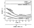
- FIG. 6 shows the results obtained in the experiment, in which the refrigerator temperature and freezer temperature corresponding to the outside air temperature are shown for each of the three types of rotation speeds (1600 rpm, 3200 rpm, 4200 rpm) of the compressor 10.
- the control unit 14 switches on / off driving (ON / OFF) of the compressor 10 and the blower 8 based on the refrigerator compartment temperature Rt detected by the refrigerator compartment temperature detector 12, and the temperature of the refrigerator compartment 4 is set at a preset target temperature. Control (e.g. 4 ° C) is maintained.
- the controller 14 drives the compressor 10 and the blower 8 (drive ON) to store the refrigerator. 4 and the freezer compartment 3 are cooled simultaneously. Moreover, the control part 14 will stop the drive of the compressor 10 and the air blower 8 if the refrigerator compartment temperature Rt which the refrigerator compartment temperature detection part 12 detected reaches
- control unit 14 performs the cooling operation in the first cooling mode, the second cooling mode, and the third cooling mode that are switched based on the outside air temperature detected by the outside air temperature detecting unit 11.
- Each of the first cooling mode, the second cooling mode, and the third cooling mode is controlled so that the freezer compartment temperature can be maintained at a preset target temperature of, for example, ⁇ 18 ° C. or lower as shown by a thin broken line in FIG. .
- the second cooling mode is executed when the outside air temperature is in a predetermined temperature range (for example, 20 ° C. or more and less than 35 ° C.).
- the rotation speed of the compressor 10 is set to 1600 rpm, for example, and the energy saving operation of the refrigerator 1 can be realized.
- FIG. 7 shows changes in the refrigerator compartment temperature Rt and the freezer compartment temperature Ft in the second cooling mode.
- the drive ON time of the compressor 10 and the blower 8 is set. Is Ton2, and the drive OFF time is Toff2.
- the freezer compartment temperature Ft at this time is approximately the freezer compartment target temperature.
- FIG. 8 shows changes in the refrigerator compartment temperature Rt and the freezer compartment temperature Ft when the outside air temperature is lower than a predetermined first switching temperature (for example, 20 ° C.) (first cooling mode).
- a predetermined first switching temperature for example, 20 ° C.
- the rotational speed of the compressor 10 is set to 4200 rpm, for example, and the cooling capacity for the refrigerator compartment 4 and the freezer compartment 3 is made higher than that in the second cooling mode. Therefore, even if it is short time (Ton1), the freezer compartment 3 can be cooled to target temperature.
- the cooling capacity is increased by increasing the number of rotations of the compressor 10, not only the cooling capacity of the freezer compartment 3 but also the cooling capacity of the refrigerator compartment 4 is increased. Therefore, the gradient of the descending line (double line) of the refrigerating room temperature Rt in FIG. 8 also increases and the driving ON time Ton1 of the compressor 10 and the blower 8 is strictly shortened.
- the path 6R for discharging the cold air to the refrigerating chamber 4 has a larger flow path resistance than the path 6F for discharging the cold air to the freezer compartment 3, so that the increase or decrease in the cooling capacity is refrigerated.
- the influence on the temperature change of the chamber 4 is smaller than the influence on the temperature change of the freezer room 3.
- the freezer compartment temperature Ft can be set to the target temperature while maintaining the refrigerator compartment temperature Rt.
- the third cooling mode is executed when the outside air temperature is higher than a predetermined second switching temperature (for example, 35 ° C.).
- a predetermined second switching temperature for example, 35 ° C.
- the rotational speed of the compressor 10 is set to 4200 rpm, for example, and the cooling capacity for the refrigerator compartment 4 and the freezer compartment 3 is higher than that in the second cooling mode.
- the refrigerator compartment temperature Rt rises as shown in FIG. 6. Therefore, the cooling capacity is increased by increasing the number of revolutions of the compressor 10 to keep the refrigerator compartment temperature Rt at the target temperature. .
- the ratio of driving ON of the compressor 10 and the blower 8 (operation rate) may be higher than in the second cooling mode, and the cooling capacity is also increased.
- the freezer compartment 3 is cooled with a high cooling capacity for a long time, and the freezer compartment temperature Ft may become below target temperature.
- the freezer compartment 3 only needs to be at a predetermined temperature (for example, ⁇ 18 ° C.) or less, it can be used without any problem as the temperature decreases.
- the refrigerator compartment automatically. 4 and the temperature of the freezer compartment 3 are controlled so as to maintain a preset target temperature (for example, a refrigerator compartment temperature of 4 ° C. and a freezer compartment temperature of ⁇ 18 ° C. or lower).
- a preset target temperature for example, a refrigerator compartment temperature of 4 ° C. and a freezer compartment temperature of ⁇ 18 ° C. or lower.
- the refrigerator in order to avoid that the freezer compartment does not fall to a preset target temperature when the outside air temperature is relatively lowered in winter, the refrigerator is refrigerated from the blower so that the amount of cold air discharged to the refrigerator compartment is reduced.
- the amount of cold air flowing through the path for discharging cold air into the chamber was manually set.
- the refrigerator 1 of the said embodiment makes the rotation speed of the compressor 10 larger than the 2nd cooling mode in the 1st cooling mode in case the outside air temperature is lower than the 1st switching temperature.
- the compressor 10 is driven at a higher rotation, the refrigerator compartment 4 and the freezer compartment 3 may be rapidly cooled and the operating rate of the compressor 10 may be reduced, but cold air is discharged from the blower 8 to the refrigerator compartment 4.
- the cooling rate of the refrigerator compartment 4 does not change so much, and the operating rate of the compressor 10 decreases significantly. do not do.
- the flow path resistance of the path 6F is small, the improvement of the cooling capacity by driving the compressor 10 at a higher rotation directly lowers the freezer compartment temperature Ft. As a result, the freezer compartment 3 is lowered to a preset target temperature.
- the rotation speed of the compressor 10 of 1st cooling mode is set to 2nd cooling mode.
- the rotational speed of the blower 8 in the first cooling mode may be set larger than that in the second cooling mode.
- the cooling capacity may be increased by lowering the temperature of the evaporator 7 by reducing the throttle amount of the expansion valve (not shown) of the refrigeration cycle than in the second cooling mode.
- FIG. 9 is a graph for explaining the cooling control corresponding to the outside air temperature of the refrigerator. Since the basic configuration of this embodiment is the same as that of the first embodiment described above, the same components as those of the first embodiment are denoted by the same reference numerals and the description thereof is omitted. And
- FIG. 9 is similar to FIG. 6, the horizontal axis indicates the outside air temperature (° C.) of the refrigerator 1, and the vertical axis indicates the temperature (° C.) inside the refrigerator 1 (the refrigerator compartment 4 and the freezer compartment 3).
- the outside air temperature detection unit 11 detects the outside air temperature based on the OFF time of the compressor 10.
- the refrigerator 1 determines that the outside air temperature is lower than the first switching temperature (for example, 20 ° C.) when the off time of the compressor 10 is longer than the first predetermined time (for example, 60 minutes), and the outside temperature is switched to the first when the time is short. It is determined that the temperature is higher than the temperature (for example, 20 ° C.). Further, the refrigerator 1 determines that the outside air temperature is higher than the second switching temperature (for example, 35 ° C.) when the off time of the compressor 10 is shorter than the second predetermined time (for example, 20 minutes). 2 It is determined that the temperature is lower than the switching temperature (for example, 35 ° C.).
- the off time (min) of the compressor 10 is described in association with the outside air temperature (° C.) of the refrigerator 1 below the horizontal axis in FIG. 9. ing.
- the refrigerator 1 operates in the first cooling mode when the off time of the compressor 10 is 60 minutes or more, operates in the second cooling mode when it is 20 minutes or more and less than 60 minutes, If it is less than a minute, operate in the third cooling mode.
- the refrigerator 1 of the second embodiment automatically sets the temperatures of the refrigerator compartment 4 and the freezer compartment 3 to the preset target temperatures (for example, the refrigerator compartment temperature of 4 ° C., the freezer compartment temperature of ⁇ 18 ° C. or lower). ) Is maintained.
- the preset target temperatures for example, the refrigerator compartment temperature of 4 ° C., the freezer compartment temperature of ⁇ 18 ° C. or lower.
- FIG. 10 is an explanatory diagram of drive control of the compressor and blower of the refrigerator. Since the basic configuration of this embodiment is the same as that of the first embodiment described above, the same components as those of the first embodiment are denoted by the same reference numerals and the description thereof is omitted. And
- the rotation speed of the compressor 10 is reduced when the outside air temperature is relatively lowered. May have to be raised to the maximum.
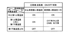
- the refrigerator 1 of the third embodiment uses the fact that the temperature detected by the evaporator temperature detection unit 13 when the drive of the compressor 10 is off is substantially the same as the temperature of the freezer compartment 3. And drive control of the air blower 8 is performed. Thereby, the control part 14 of the refrigerator 1 of the compressor 10 and the air blower 8 is based on the refrigerator temperature Et detected by the refrigerator temperature detection part 13, and the evaporator temperature Et detected by the evaporator temperature detection part 13. The driving is switched on and off, and the temperature of the refrigerator compartment 4 is controlled so as to maintain a preset target temperature (for example, 4 ° C.).
- a preset target temperature for example, 4 ° C.
- the control unit 14 drives the compressor 10 and the blower 8 (drive ON) when the refrigerator compartment temperature Rt detected by the refrigerator compartment temperature detector 12 reaches a predetermined first upper limit temperature (drive ON). 4 and the freezer compartment 3 are cooled simultaneously. Further, the control unit 14 determines that the evaporator temperature Et detected by the evaporator temperature detector 13 reaches a predetermined evaporator upper limit temperature, and the refrigerator compartment temperature Rt detected by the refrigerator compartment temperature detector 12 is less than the first lower limit temperature. When the temperature is too high, the compressor 10 and the blower 8 are driven (drive ON) to cool the refrigerator compartment 4 and the freezer compartment 3 simultaneously.
- the compressor 10 and the blower 8 are driven even if the refrigerator compartment temperature Rt does not reach the first upper limit temperature ( Drive ON)
- the refrigerator compartment 4 and the freezer compartment 3 can be cooled. Accordingly, even when the operating temperature of the compressor 10 and the blower 8 cannot be secured above a predetermined value because the outside air temperature is low, the compressor 10 and the blower 8 can be driven by detecting the temperature rise of the evaporator temperature Et. . For this reason, it becomes unnecessary to set the cooling capacity corresponding to the state in which the operating rates of the compressor 10 and the blower 8 are less than the predetermined value. Therefore, it is possible to maintain the temperatures of the refrigerator compartment 4 and the freezer compartment 3 at a preset target temperature within a wide range of outside air temperature without increasing the variable range of the cooling capacity.
- FIG. 11 is an explanatory diagram of drive control of the refrigerator compressor and blower. Since the basic configuration of this embodiment is the same as that of the first embodiment described above, the same components as those of the first embodiment are denoted by the same reference numerals and the description thereof is omitted. And
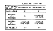
- the refrigerator 1 of the fourth embodiment has a second upper limit temperature between the first upper limit temperature and the first lower limit temperature of the refrigerating room temperature Rt in order to realize a more preferable cooling operation as compared with the third embodiment. Is provided to ensure a certain range (minimum differential) of the control temperature range of the refrigerator compartment temperature Rt.
- the controller 14 drives the compressor 10 and the blower 8 (drive ON) to store the refrigerator. 4 and the freezer compartment 3 are cooled simultaneously. Further, the control unit 14 determines that the evaporator temperature Et detected by the evaporator temperature detector 13 reaches a predetermined evaporator upper limit temperature, and the refrigerator compartment temperature Rt detected by the refrigerator compartment temperature detector 12 is greater than the second upper limit temperature. When the temperature is too high, the compressor 10 and the blower 8 are driven (drive ON) to cool the refrigerator compartment 4 and the freezer compartment 3 simultaneously.
- the outside air temperature detection unit 11 detects the outside air temperature based on the temperature rise time when the temperature of the refrigerator compartment 4 rises to the second upper limit temperature.
- the refrigerator 1 determines that the outside air temperature is lower than the first switching temperature (for example, 20 ° C.) when the temperature rise time to the second upper limit temperature of the refrigerator compartment 4 is longer than the third predetermined time (for example, 20 minutes), and is short. Sometimes it is determined that the outside air temperature is higher than the first switching temperature (for example, 20 ° C.). Furthermore, the refrigerator 1 determines that the outside air temperature is higher than the second switching temperature (for example, 35 ° C.) when the temperature rise time to the second upper limit temperature of the refrigerator compartment 4 is shorter than the fourth predetermined time (for example, 10 minutes). When it is long, the outside air temperature is determined to be lower than the second switching temperature (for example, 35 ° C.).
- the first temperature of the refrigerator compartment 4 is associated with the outside air temperature (° C.) of the refrigerator 1 below the horizontal axis in FIG. 2 Temperature rise time (min) up to the upper limit temperature is described.
- the refrigerator 1 is operated in the first cooling mode when the temperature rise time to the second upper limit temperature of the refrigerator compartment 4 is 20 minutes or more, and is second when it is 10 minutes or more and less than 20 minutes. It operates in the cooling mode and operates in the third cooling mode when it is less than 10 minutes.
- the compression is performed.
- the compressor 10 in a short period in which the refrigerator compartment temperature Rt reaches the first lower limit temperature immediately after the start of the drive of the compressor 10 and the blower 8 and the drive of the compressor 10 and the blower 8 is stopped. And the ON / OFF operation (chattering) of the blower 8 can be prevented.
- FIG. 12 shows a graph for explaining the temperatures of the refrigerator compartment 4 and the freezer compartment 3 corresponding to the outside air temperature of the refrigerator 1 when the third embodiment and the fourth embodiment are used.
- the freezer temperature corresponding to each of the three rotation speeds of the compressor 10 is the first and second embodiments (solid line in FIG. 12). It can be seen that the temperature decreases with respect to the freezer compartment temperature shown (the freezer compartment temperature indicated by a dotted line in FIG. 12).
- the evaporator temperature Et reaches a predetermined evaporator upper limit temperature
- the compressor 10 and the blower 8 are driven (driving) even if the refrigerator compartment temperature Rt does not reach the predetermined first upper limit temperature. ON), because the refrigerator compartment 4 and the freezer compartment 3 are cooled at the same time, even if the outside air temperature is low, an extreme decrease in the operation rate can be suppressed.
- FIG. 13 is a block diagram showing the configuration of the refrigerator. Since the basic configuration of this embodiment is the same as that of the first embodiment described above, the same components as those of the first embodiment are denoted by the same reference numerals and the description thereof is omitted. And
- Refrigerator 1 includes a freezer compartment temperature detector 15 as shown in FIG.
- the freezer compartment temperature detection unit 15 detects the storage temperature inside the freezer compartment 3.
- the refrigerator 1 uses the freezer compartment temperature detector 15 instead of the evaporator temperature detector 13 used in the third and fourth embodiments, and executes drive control of the compressor 10 and the blower 8.
- the control part 14 of the refrigerator 1 is based on the temperature of the refrigerator compartment 4 which the refrigerator compartment temperature detection part 12 detected, and the compressor 10 and air blower based on the temperature of the freezer compartment 3 which the freezer compartment temperature detection part 15 detected. 8 is switched on and off, and the temperature of the refrigerator compartment 4 is controlled to maintain a preset target temperature (for example, 4 ° C.).
- the controller 14 detects that the temperature of the freezer compartment 3 detected by the freezer compartment temperature detector 15 reaches a predetermined freezer compartment upper limit temperature and the temperature of the refrigerator compartment 4 detected by the refrigerator compartment temperature detector 12 is lower than the first lower limit temperature.
- the compressor 10 and the blower 8 are driven (drive ON) to cool the refrigerator compartment 4 and the freezer compartment 3 simultaneously.
- the refrigerator 1 is connected to the refrigerator compartment 4 for storing stored items in a refrigerator, the freezing chamber 3 for storing stored items in a frozen state, the compressor 10 for operating a refrigeration cycle, and generating cold air by connecting to the compressor 10.
- An evaporator 7 that performs cooling
- a blower 8 that sends out the cold air generated by the evaporator 7 to the refrigerator compartment 4 and the freezer compartment 3
- a refrigerator compartment temperature detector 12 that detects the temperature of the refrigerator compartment 4, and an outside that detects the outside air temperature.
- the refrigerator 1 has the refrigerator compartment 4 and the freezer compartment in the first cooling mode in which the outside air temperature is lower than a predetermined first switching temperature (for example, 20 ° C.) than in the second cooling mode in which the outside air temperature is higher than the first switching temperature.
- the cooling capacity for 3 is high.
- the refrigerator 1 increases the cooling capacity in the first cooling mode, for example, by controlling the number of revolutions of the compressor 10 and the blower 8 in the second cooling mode.
- the user can automatically adjust the temperature of the refrigerator compartment 4 without manually opening and closing the shutter and the like.
- the rotation speed (4200 rpm or 3200 rpm) of the compressor 10 in the first cooling mode is larger than the rotation speed (1600 rpm) of the compressor 10 in the second cooling mode.
- the cooling capacity can be increased more than in the second cooling mode by controlling the rotational speed of the compressor 10 in the first cooling mode. Therefore, the temperature of the refrigerator compartment 4 can be easily adjusted.
- the rotation speed of the air blower 8 of a 1st cooling mode become larger than a 2nd cooling mode.
- the cooling capacity can be increased more than in the second cooling mode by controlling the rotational speed of the blower 8 during the first cooling mode. Therefore, the temperature of the refrigerator compartment 4 can be easily adjusted.
- the outside air temperature detection unit 11 detects the outside air temperature based on the off time of the compressor 10, and the outside air temperature is first when the off time of the compressor 10 is longer than a first predetermined time (for example, 60 minutes).
- a first predetermined time for example, 60 minutes.
- the outside air temperature is determined to be higher than the first switching temperature (for example, 20 ° C.).
- the outside air temperature can be estimated without using a sensor or the like that directly detects the outside air temperature as the outside air temperature detecting unit 11. Therefore, it is not necessary to provide a sensor for directly detecting the outside air temperature, and it is possible to reduce the number of parts and the manufacturing process.
- the refrigerator 1 has a channel resistance higher than the path 6R and the discharge port 6b of the cool passage 6 through which the cool passage 6F and the discharge port 6a of the cool passage 6 discharge cool air from the blower 8 to the freezer compartment 3. Is small.
- the amount of cold air discharged into the freezer compartment 3 by the blower 8 is larger than the amount of cold air discharged into the refrigerator compartment 4. According to these structures, it becomes easier to cool the freezer compartment 3 than the refrigerator compartment 4. That is, the temperature in the freezer compartment 3 is more likely to be lower than that in the refrigerator compartment 4. Therefore, it is possible to easily manage the temperature of the refrigerator compartment 4 and the temperature of the freezer compartment 3 at respective preset target temperatures without using a damper or a shutter.
- the refrigerator 1 also includes an evaporator temperature detector 13 for detecting the temperature of the evaporator 7 and controlling the defrosting operation of the evaporator 7.
- the refrigerator 1 is configured such that the temperature detected by the evaporator temperature detector 13 reaches a predetermined evaporator upper limit temperature and the temperature detected by the refrigerator temperature detector 12 is higher than the first lower limit temperature or the first upper limit temperature.
- the compressor 10 and the blower 8 are driven. According to this configuration, the temperature of the freezer compartment 3 can be estimated from the detected temperature of the evaporator temperature detector 12. Therefore, it is possible to adjust the temperature of the refrigerator compartment 4 and the freezer compartment 3 with suitable accuracy.
- the refrigerator 1 includes a freezer compartment temperature detection unit 15 that detects the temperature of the freezer compartment 3.
- the refrigerator 1 includes the compressor 10 and the blower when the temperature detected by the freezer temperature detector 15 reaches a predetermined freezer upper limit temperature and the temperature detected by the refrigerator temperature detector 12 is higher than the first lower limit temperature. 8 is driven. According to this configuration, the temperature of the freezer compartment 3 can be directly detected by the freezer compartment temperature detector 15. Therefore, it is possible to adjust the temperature of the refrigerator compartment 4 and the freezer compartment 3 with a more suitable accuracy.
- the refrigerator 1 which does not mount the damper for temperature control of the refrigerator compartment 4, a user does not need to open and close a shutter etc. manually, and a refrigerator with favorable usability 1 can be provided.
- the present invention can be used in a refrigerator.
Landscapes
- Engineering & Computer Science (AREA)
- Chemical & Material Sciences (AREA)
- Combustion & Propulsion (AREA)
- Physics & Mathematics (AREA)
- Mechanical Engineering (AREA)
- Thermal Sciences (AREA)
- General Engineering & Computer Science (AREA)
- Devices That Are Associated With Refrigeration Equipment (AREA)
- Cold Air Circulating Systems And Constructional Details In Refrigerators (AREA)
Abstract
冷蔵庫1は冷蔵室4と、冷凍室3と、冷凍サイクルを運転する圧縮機10と、圧縮機10に接続して冷気を生成する蒸発器7と、蒸発器7で生成した冷気を冷蔵室4及び冷凍室3に送出する送風機8と、冷蔵室温度検知部12と、外気温検知部11とを備え、冷蔵室温度検知部12の検知温度が所定の第1上限温度に到達すると圧縮機10及び送風機8を駆動して冷蔵室4及び冷凍室3を同時に冷却し、所定の第1下限温度に到達すると圧縮機10及び送風機8を停止する。冷蔵庫1は外気温が所定の第1切替温度よりも低温の第1冷却モード時に、第1切替温度よりも高温の第2冷却モード時よりも冷蔵室4及び冷凍室3に対する冷却能力が高い。
Description
本発明は冷蔵庫に関する。
従来の冷蔵庫が特許文献1に開示されている。この冷蔵庫は冷蔵室に冷気を流通させるためのダクトに、ダクトの開口面積を増減させるシャッターを備える。そして、シャッターの開閉により冷蔵室内の冷気循環量を増減させて圧縮機の運転時間を制御し、冷凍室の温度を調節している。これにより、冷凍室用の温度センサや冷蔵室の温度調整用のダンパーを搭載しない安価な冷蔵庫を提供している。
しかしながら、上記従来の冷蔵庫は外気温の変化に応じて使用者がシャッターの開閉を手動で行う必要があった。例えば、冬季に外気温が比較的低下した場合に外気温と冷蔵室の温度とが接近すると、冷蔵庫の圧縮機の運転率が低下して冷凍室が予め設定した目標温度まで低下しないという状態が生じる虞があった。そのため、使用者がシャッターの開閉を手動で行う必要があり、手間がかかって使い勝手が良くないという課題があった。
本発明は上記の点に鑑みなされたものであり、冷蔵室の温度調整用のダンパーを搭載しない冷蔵庫において、使用者がシャッター等の開閉を手動で行う必要がなく、使い勝手が良好な冷蔵庫を提供することを目的とする。
上記の課題を解決するため、本発明は、貯蔵物を冷蔵保存する冷蔵室と、貯蔵物を冷凍保存する冷凍室と、冷凍サイクルを運転する圧縮機と、前記圧縮機に接続して冷気を生成する蒸発器と、前記蒸発器で生成した冷気を前記冷蔵室及び前記冷凍室に送出する送風機と、前記冷蔵室の温度を検知する冷蔵室温度検知部と、外気温を検知する外気温検知部とを備え、前記冷蔵室温度検知部の検知温度が所定の第1上限温度に到達すると前記圧縮機及び前記送風機を駆動して前記冷蔵室及び前記冷凍室を同時に冷却し、所定の第1下限温度に到達すると前記圧縮機及び前記送風機を停止する冷蔵庫において、外気温が所定の切替温度よりも低温の第1冷却モード時に、前記切替温度よりも高温の第2冷却モード時よりも前記冷蔵室及び前記冷凍室に対する冷却能力が高いことを特徴としている。
また、上記構成の冷蔵庫において、第1冷却モードの前記圧縮機の回転数が第2冷却モードよりも大きいことを特徴としている。
また、上記構成の冷蔵庫において、第1冷却モードの前記送風機の回転数が第2冷却モードよりも大きいことを特徴としている。
また、上記構成の冷蔵庫において、前記外気温検知部が前記圧縮機のオフ時間に基づいて外気温を検知し、前記オフ時間が所定時間よりも長い時に外気温が前記切替温度よりも低温と判断して短い時に外気温が前記切替温度よりも高温と判断することを特徴としている。
また、上記構成の冷蔵庫において、前記送風機から前記冷凍室に冷気を吐出する経路の流路抵抗が前記冷蔵室に冷気を吐出する経路の流路抵抗よりも小さいことを特徴としている。
また、上記構成の冷蔵庫において、前記送風機により前記冷凍室に吐出される冷気の風量が前記冷蔵室に吐出される冷気の風量よりも多いことを特徴としている。
また、上記構成の冷蔵庫において、前記蒸発器の温度を検知して前記蒸発器の除霜運転を制御するための蒸発器温度検知部を備え、前記蒸発器温度検知部の検知温度が所定の蒸発器上限温度に到達し、且つ前記冷蔵室温度検知部の検知温度が第1下限温度よりも高温の場合または第1上限温度と第1下限温度との間の第2上限温度よりも高温の場合に前記圧縮機及び前記送風機を駆動することを特徴としている。
また、上記構成の冷蔵庫において、前記冷凍室の温度を検知する冷凍室温度検知部を備え、前記冷凍室温度検知部の検知温度が所定の冷凍室上限温度に到達して前記冷蔵室温度検出部の検知温度が第1下限温度よりも高温の場合に前記圧縮機及び前記送風機を駆動することを特徴としている。
本発明の構成によれば、冷蔵室の温度調整用のダンパーを搭載しない冷蔵庫において、使用者がシャッター等の開閉を手動で行う必要がなく、使い勝手が良好な冷蔵庫を提供することができる。
以下、本発明の実施形態を図1~図13に基づき説明する。
<第1実施形態>
最初に、本発明の第1実施形態の冷蔵庫について、図1~図3を用いてその構造と動作の概略を説明する。図1及び図2は冷蔵庫の垂直断面側面図及び正面図、図3は冷蔵庫の構成を示すブロック図である。図1において左方が冷蔵庫の前面側、右方が冷蔵庫の背面側である。また、図1及び図2は冷蔵庫の正面に設けられる扉と、冷凍室及び冷蔵室の内部の背面側に設けられる冷気通路との間の仕切り板の描画を省略している。
最初に、本発明の第1実施形態の冷蔵庫について、図1~図3を用いてその構造と動作の概略を説明する。図1及び図2は冷蔵庫の垂直断面側面図及び正面図、図3は冷蔵庫の構成を示すブロック図である。図1において左方が冷蔵庫の前面側、右方が冷蔵庫の背面側である。また、図1及び図2は冷蔵庫の正面に設けられる扉と、冷凍室及び冷蔵室の内部の背面側に設けられる冷気通路との間の仕切り板の描画を省略している。
冷蔵庫1は、図1及び図2に示すように断熱構造の本体筐体2を備える。本体筐体2はその内部に食品等の貯蔵物を冷凍保存する冷凍室3を上段に備え、冷蔵保存する冷蔵室4を下段に備える。冷凍室3及び冷蔵室4の前面は各々別個の断熱構造の扉(不図示)によって開閉される。冷凍室3と冷蔵室4との間は仕切り部5によって仕切られる。
冷凍室3の後方には庫内の上下方向に延びる冷気通路6が設けられる。冷気通路6の内部には冷却器である蒸発器7と、送風機8とが配置される。送風機8は蒸発器7に対して冷気流通方向下流側に配置される。冷気通路6は送風機8の下流側で冷凍室3に冷気を吐出する経路6Fと冷蔵室4に冷気を吐出する経路6Rとに分岐する。経路6Fには冷凍室3に対する冷気の吐出口6aが設けられ、経路6Rには冷蔵室4に対する冷気の吐出口6bが設けられる。従来技術では経路6Rにシャッターなどの冷気流量制限機構が設けられ、使用者が手動で流量を設定していた。冷蔵室4の後方には冷蔵室4の内部の冷気を蒸発器7の冷気流通方向上流側に戻す連通路(不図示)が設けられる。
送風機8を駆動すると、冷気通路6の内部を空気が流通する。送風機8の冷気流通方向上流側では、空気が蒸発器7を通る間に冷却されて冷気となる。送風機8の下流側で冷気は吐出口6aを通じて冷凍室3に吐出され、吐出口6bを通じて冷蔵室4に吐出される。
なお、冷気通路6は送風機8から冷凍室3に冷気を吐出する経路6F及び吐出口6aが、送風機8から冷蔵室4に冷気を吐出する経路6R及び吐出口6bよりも流路抵抗が小さくなるように形成される。図1及び図2に示すように、経路6Fは幅広で且つ経路長が短く形成され、また冷凍室3に開口する吐出口6aは大きく形成される。これに対して、経路6Rは細く且つ経路長が長く形成され、また冷蔵室4に開口する吐出口6bは吐出口6aよりも小さく形成される。これにより、送風機8により冷凍室3に吐出される冷気の風量が冷蔵室4に吐出される冷気の風量よりも多くなる。
本体筐体2の背面下部には機械室9が形成される。機械室9には冷凍サイクルを運転する圧縮機10が配置される。また、本体筐体2の左右の側面や上面、背面などの壁部の中には、本体筐体2の表面等を通じて放熱する凝縮器(不図示)が張り巡らされる。
また、冷蔵庫1は、図3に示すように外気温検知部11、冷蔵室温度検知部12及び蒸発器温度検知部13を備える。外気温検知部11は冷蔵庫1の外部周囲の外気温を検知する。冷蔵室温度検知部12は冷蔵室4の内部の貯蔵温度を検知する。蒸発器温度検知部13は蒸発器7の近傍に配置される。蒸発器温度検知部13は蒸発器7の着霜とその解消に係る除霜運転を制御するために、蒸発器7の温度を検知する。
冷蔵庫1はその全体の動作制御を行うために、本体筐体2に図3に示す制御部14を収容する。制御部14は不図示の演算部や記憶部等を備え、記憶部等に記憶、入力されたプログラム、データに基づき圧縮機10や送風機8などの駆動を制御し、庫内温度が予め設定された目標温度を維持するように冷凍サイクルを運転させる。この運転にあたって、制御部14は外気温検知部11及び冷蔵室温度検知部12が検知した冷蔵庫1の外部周囲の外気温や冷蔵室4の内部の温度に基づいて関連する構成要素を制御し、好適な運転を実現する。さらに、制御部14は蒸発器温度検知部13から得られる蒸発器7の着霜に関する温度情報に基づいて関連する構成要素を制御する。
続いて、冷蔵庫1の冷却運転の詳細について、図4~図6を用いて説明する。図4は冷蔵庫1の圧縮機10及び送風機8の駆動制御の説明図、図5は冷蔵室の温度推移を示すグラフ、図6は冷蔵庫1の外気温に対応した冷却制御を説明するためのグラフである。
なお、図5の横軸は時間を示し、縦軸は冷蔵庫1の冷蔵室温度Rtを示す。また、図6の横軸は冷蔵庫1の外気温(℃)を示し、縦軸は冷蔵庫1の庫内(冷蔵室4及び冷凍室3)の温度(℃)を示す。図6は実験で得られた結果であって、外気温に対応した冷蔵室温度及び冷凍庫温度を圧縮機10の3種類の回転数(1600rpm、3200rpm、4200rpm)ごとに記載している。
制御部14は冷蔵室温度検知部12が検知した冷蔵室温度Rtに基づいて圧縮機10及び送風機8の駆動のオンオフ(ON/OFF)を切り替え、冷蔵室4の温度が予め設定された目標温度(例えば4℃)を維持するよう制御する。
図4に示すように、制御部14は冷蔵室温度検知部12が検知した冷蔵室温度Rtが所定の第1上限温度に到達すると圧縮機10及び送風機8を駆動して(駆動ON)冷蔵室4及び冷凍室3を同時に冷却する。また、制御部14は冷蔵室温度検知部12が検知した冷蔵室温度Rtが所定の第1下限温度に到達すると圧縮機10及び送風機8の駆動を停止する(駆動OFF)。なお、第1上限温度が第1下限温度よりも高い温度に設定されるため、冷蔵室温度Rtは第1上限温度と第1下限温度との間になるよう制御される。例えば、目標温度を4℃とした場合には第1上限温度が6℃に設定され、第1下限温度が2℃に設定される。
また、制御部14は外気温検知部11が検知した外気温に基づいて切り替える第1冷却モード、第2冷却モード及び第3冷却モードで冷却運転を実行する。第1冷却モード、第2冷却モード及び第3冷却モードは各々、図6に細い破線で示したように冷凍室温度が例えば-18℃以下を予め設定した目標温度として維持できるように制御される。
図6に示すように、第2冷却モードは外気温が所定の温度範囲(例えば20℃以上、35℃未満)である場合に実行される。第2冷却モードでは圧縮機10の回転数を例えば1600rpmに設定し、冷蔵庫1の省エネ運転を実現できる。
続いて、第2冷却モードにおける冷蔵室温度Rt及び冷凍室温度Ftの推移を図7に示す。この外気温の例においては圧縮機10の回転数を1600rpmとして冷蔵室温度Rtが第1上限温度と第1下限温度との間になるよう制御した場合、圧縮機10及び送風機8の駆動ON時間はTon2であり、駆動OFF時間はToff2である。そして、このときの冷凍室温度Ftは概ね冷凍室目標温度となっている。
次に、外気温が所定の第1切替温度(例えば20℃)よりも低温である場合(第1冷却モード)の冷蔵室温度Rt及び冷凍室温度Ftの推移を図8に示す。外気温が低温である場合、冷蔵室温度Rtと外気温との差が小さいために圧縮機10及び送風機8の駆動ON時間は短くなる(Ton1<Ton2)。また、圧縮機10及び送風機8を駆動OFFにしたときの冷蔵室4の温度上昇も緩やかになる(Toff1>Toff2)。すなわち、圧縮機10及び送風機8の駆動ONの比率(運転率)が低下する。この場合、圧縮機10の回転数を上述の第2冷却モードと同じ1600rpmとすると、冷凍室3を冷却する時間が不足気味になって冷凍室3が目標温度に到達しないことがある。
そこで、第1冷却モードでは圧縮機10の回転数を例えば4200rpmに設定し、第2冷却モード時よりも冷蔵室4及び冷凍室3に対する冷却能力を高くする。これにより、短い時間(Ton1)であっても冷凍室3を目標温度にまで冷却することができる。
圧縮機10の回転数を上げるなど冷却能力を高くした場合、冷凍室3の冷却能力だけでなく、冷蔵室4の冷却能力も上がる。したがって、図8における冷蔵室温度Rtの下降線(2重線)の勾配も大きくなって圧縮機10及び送風機8の駆動ON時間Ton1は厳密には短くなる。しかしながら、図1や図2で示したように、冷蔵室4に冷気を吐出する経路6Rは冷凍室3に冷気を吐出する経路6Fに比べて流路抵抗が大きいため、冷却能力の増減が冷蔵室4の温度変化に及ぼす影響は冷凍室3の温度変化に及ぼす影響に比べて小さい。すなわち、冷却能力を高くした場合の圧縮機10及び送風機8の駆動ON時間Ton1の短縮はわずかであるため、冷凍室温度Ftの下降線の勾配の増加が冷凍室3の温度低下に直接的に影響を及ぼす。したがって、外気温の低い第1冷却モードでは冷却能力を高くすることで、冷蔵室温度Rtを維持しながら冷凍室温度Ftを目標温度にすることができる。
第3冷却モードは外気温が所定の第2切替温度(例えば35℃)よりも高温である場合に実行される。第3冷却モードでは圧縮機10の回転数を例えば4200rpmに設定し、第2冷却モード時よりも冷蔵室4及び冷凍室3に対する冷却能力が高い。
外気温が高温である場合、図6に示すように冷蔵室温度Rtが上昇してしまうため、圧縮機10の回転数を上げるなどして冷却能力を高めて冷蔵室温度Rtを目標温度に保つ。このとき、圧縮機10及び送風機8の駆動ONの比率(運転率)が第2冷却モードよりも高くなることがあり、冷却能力も高くしている。これにより、冷凍室3が長時間にわたって高い冷却能力で冷却され、冷凍室温度Ftは目標温度以下となる可能性がある。しかしながら、冷凍室3は所定の温度(例えば-18℃)以下となっていればよいので、温度が下がる分には問題なく使用できる。
このようにして、冷蔵室4の温度調整用のダンパーを搭載しない冷蔵庫1において、使用者がシャッター等の開閉によって経路6Rを流通する冷気量を手動で設定しなくても、自動的に冷蔵室4及び冷凍室3の温度が予め設定された目標温度(例えば冷蔵室温度4℃、冷凍室温度-18℃以下)を維持するよう制御される。
従来技術では、例えば冬季に外気温が比較的低下した場合に冷凍室が予め設定した目標温度まで低下しないことを回避するため、冷蔵室に吐出される冷気の風量が少なくなるように送風機から冷蔵室に冷気を吐出する経路を流通する冷気量を手動で設定していた。これに対して、上記実施形態の冷蔵庫1は外気温が第1切替温度よりも低温である場合の第1冷却モードにおいて圧縮機10の回転数を第2冷却モードよりも大きくしている。圧縮機10をより高回転で駆動すると、冷蔵室4及び冷凍室3が急速に冷却されて圧縮機10の運転率が低下する可能性があるが、送風機8から冷蔵室4に冷気を吐出する経路6Rの流路抵抗が送風機8から冷凍室3に冷気を吐出する経路6Fの流路抵抗に比べて大きいため、冷蔵室4の冷却速度はあまり変わらず、圧縮機10の運転率もさほど低下しない。一方、経路6Fの流路抵抗が小さいので、圧縮機10をより高回転で駆動することによる冷却能力の向上は直接的に冷凍室温度Ftを低下させる。その結果、冷凍室3が予め設定した目標温度まで低下する。
また、上記実施形態では、第1冷却モード時に第2冷却モード時よりも冷蔵室4及び冷凍室3に対する冷却能力を高めるために、第1冷却モードの圧縮機10の回転数を第2冷却モードよりも大きくすることとしたが、第1冷却モードの送風機8の回転数を第2冷却モードよりも大きくすることにしても良い。また、例えば第1冷却モードにおいて冷凍サイクルの膨張弁(不図示)の絞り量を第2冷却モードよりも絞るなどして蒸発器7の温度を下げることで冷却能力を上げても良い。
<第2実施形態>
次に、本発明の第2実施形態の冷蔵庫について、図9を用いて説明する。図9は冷蔵庫の外気温に対応した冷却制御を説明するためのグラフである。なお、この実施形態の基本的な構成は先に説明した第1実施形態と同じであるので、第1実施形態と共通する構成要素には前と同じ符号を付してその説明を省略するものとする。
次に、本発明の第2実施形態の冷蔵庫について、図9を用いて説明する。図9は冷蔵庫の外気温に対応した冷却制御を説明するためのグラフである。なお、この実施形態の基本的な構成は先に説明した第1実施形態と同じであるので、第1実施形態と共通する構成要素には前と同じ符号を付してその説明を省略するものとする。
図9は図6と同様に、横軸が冷蔵庫1の外気温(℃)を示し、縦軸が冷蔵庫1の庫内(冷蔵室4及び冷凍室3)の温度(℃)を示す。
第2実施形態の冷蔵庫1は、外気温検知部11が圧縮機10のオフ(OFF)時間に基づいて外気温を検知する。冷蔵庫1は圧縮機10のオフ時間が第1所定時間(例えば60分)よりも長い時に外気温が第1切替温度(例えば20℃)よりも低温と判断し、短い時に外気温が第1切替温度(例えば20℃)よりも高温と判断する。さらに、冷蔵庫1は圧縮機10のオフ時間が第2所定時間(例えば20分)よりも短い時に外気温が第2切替温度(例えば35℃)よりも高温と判断し、長い時に外気温が第2切替温度(例えば35℃)よりも低温と判断する。
このような外気温と圧縮機10のオフ時間との関係について、図9の横軸の下方に冷蔵庫1の外気温(℃)に対応付けて、圧縮機10のオフ時間(min)を記載している。図9によれば、冷蔵庫1は圧縮機10のオフ時間が60分以上である場合に第1冷却モードで運転し、20分以上60分未満である場合に第2冷却モードで運転し、20分未満である場合に第3冷却モードで運転する。
第2実施形態の冷蔵庫1も第1実施形態と同様に、自動的に冷蔵室4及び冷凍室3の温度が予め設定された目標温度(例えば冷蔵室温度4℃、冷凍室温度-18℃以下)を維持するよう制御される。
<第3実施形態>
次に、本発明の第3実施形態の冷蔵庫について、図10を用いて説明する。図10は冷蔵庫の圧縮機及び送風機の駆動制御の説明図である。なお、この実施形態の基本的な構成は先に説明した第1実施形態と同じであるので、第1実施形態と共通する構成要素には前と同じ符号を付してその説明を省略するものとする。
次に、本発明の第3実施形態の冷蔵庫について、図10を用いて説明する。図10は冷蔵庫の圧縮機及び送風機の駆動制御の説明図である。なお、この実施形態の基本的な構成は先に説明した第1実施形態と同じであるので、第1実施形態と共通する構成要素には前と同じ符号を付してその説明を省略するものとする。
ここで、冷凍室3の温度を検知することなく冷凍室3の温度が予め設定された目標温度を維持するように制御を試みると、外気温が比較的低下した場合に圧縮機10の回転数を最高まで上げなければならないことがある。
そこで、第3実施形態の冷蔵庫1は、圧縮機10の駆動がオフの場合に蒸発器温度検知部13が検知する温度が冷凍室3の温度とほぼ同じであることを利用して圧縮機10及び送風機8の駆動制御を実行する。これにより、冷蔵庫1の制御部14は冷蔵室温度検知部12が検知した冷蔵室温度Rtと、蒸発器温度検知部13が検知したに蒸発器温度Etとに基づいて圧縮機10及び送風機8の駆動のオンオフを切り替え、冷蔵室4の温度が予め設定された目標温度(例えば4℃)を維持するよう制御する。
図10に示すように、制御部14は冷蔵室温度検知部12が検知した冷蔵室温度Rtが所定の第1上限温度に到達すると圧縮機10及び送風機8を駆動して(駆動ON)冷蔵室4及び冷凍室3を同時に冷却する。さらに、制御部14は蒸発器温度検知部13の検知した蒸発器温度Etが所定の蒸発器上限温度に到達し、且つ冷蔵室温度検知部12の検知した冷蔵室温度Rtが第1下限温度よりも高温の場合に圧縮機10及び送風機8を駆動して(駆動ON)冷蔵室4及び冷凍室3を同時に冷却する。
この構成によれば、蒸発器温度Etが所定の蒸発器上限温度に到達していれば、冷蔵室温度Rtが第1上限温度に達していなくても圧縮機10及び送風機8を駆動して(駆動ON)冷蔵室4及び冷凍室3を冷却することができる。したがって、外気温が低くて圧縮機10及び送風機8の運転率が所定値以上確保できないような状態であっても、蒸発器温度Etの温度上昇を検知して圧縮機10及び送風機8を駆動できる。このため、圧縮機10及び送風機8の運転率が所定値未満となる状態に対応する冷却能力を設定しなくてもよくなる。したがって、冷却能力の可変範囲を大きくせずに、広い外気温の範囲で冷蔵室4及び冷凍室3の温度を予め設定した目標温度で維持することが可能となる。
<第4実施形態>
次に、本発明の第4実施形態の冷蔵庫について、図11を用いて説明する。図11は冷蔵庫の圧縮機及び送風機の駆動制御の説明図である。なお、この実施形態の基本的な構成は先に説明した第1実施形態と同じであるので、第1実施形態と共通する構成要素には前と同じ符号を付してその説明を省略するものとする。
次に、本発明の第4実施形態の冷蔵庫について、図11を用いて説明する。図11は冷蔵庫の圧縮機及び送風機の駆動制御の説明図である。なお、この実施形態の基本的な構成は先に説明した第1実施形態と同じであるので、第1実施形態と共通する構成要素には前と同じ符号を付してその説明を省略するものとする。
第4実施形態の冷蔵庫1は、第3実施形態と比較してさらに好適な冷却運転を実現するために、冷蔵室温度Rtの第1上限温度と第1下限温度との間に第2上限温度を設けて冷蔵室温度Rtの制御温度範囲を一定範囲(最小ディファレンシャル)確保するものである。
図11に示すように、制御部14は冷蔵室温度検知部12が検知した冷蔵室温度Rtが所定の第1上限温度に到達すると圧縮機10及び送風機8を駆動して(駆動ON)冷蔵室4及び冷凍室3を同時に冷却する。さらに、制御部14は蒸発器温度検知部13の検知した蒸発器温度Etが所定の蒸発器上限温度に到達し、且つ冷蔵室温度検知部12の検知した冷蔵室温度Rtが第2上限温度よりも高温の場合に圧縮機10及び送風機8を駆動して(駆動ON)冷蔵室4及び冷凍室3を同時に冷却する。
なお、この冷蔵庫1は、外気温検知部11が冷蔵室4の温度が第2上限温度まで上昇するときの温度上昇時間に基づいて外気温を検知する。冷蔵庫1は冷蔵室4の第2上限温度までの温度上昇時間が第3所定時間(例えば20分)よりも長い時に外気温が第1切替温度(例えば20℃)よりも低温と判断し、短い時に外気温が第1切替温度(例えば20℃)よりも高温と判断する。さらに、冷蔵庫1は冷蔵室4の第2上限温度までの温度上昇時間が第4所定時間(例えば10分)よりも短い時に外気温が第2切替温度(例えば35℃)よりも高温と判断し、長い時に外気温が第2切替温度(例えば35℃)よりも低温と判断する。
このような外気温と冷蔵室4の第2上限温度までの温度上昇時間との関係について、図12の横軸の下方に冷蔵庫1の外気温(℃)に対応付けて、冷蔵室4の第2上限温度までの温度上昇時間(min)を記載している。図12によれば、冷蔵庫1は冷蔵室4の第2上限温度までの温度上昇時間が20分以上である場合に第1冷却モードで運転し、10分以上20分未満である場合に第2冷却モードで運転し、10分未満である場合に第3冷却モードで運転する。
圧縮機10及び送風機8の駆動を開始する際に冷蔵室4の第2上限温度を利用する場合は、第2上限温度と第1下限温度との間に最小ディファレンシャルを確保してあるので、圧縮機10及び送風機8の駆動を開始してすぐに冷蔵室温度Rtが第1下限温度に到達してしまって圧縮機10及び送風機8の駆動を停止してしまうという、短期間での圧縮機10及び送風機8のON/OFF動作(チャタリング)を防止することができる。
図12に、第3実施形態及び第4実施形態を用いた場合の、冷蔵庫1の外気温に対応した冷蔵室4及び冷凍室3の温度を説明するためのグラフを示す。図12に示すように外気温が約20℃よりも低温の温度範囲において、圧縮機10の3種類の回転数各々に対応する冷凍室温度が第1及び第2実施形態(図12に実線で示す冷凍室温度)に対して低下していることが分かる(図12に点線で示す冷凍室温度)。これは、蒸発器温度Etが所定の蒸発器上限温度に到達した場合は、冷蔵室温度Rtが所定の第1上限温度に到達していなくても圧縮機10及び送風機8を駆動して(駆動ON)、冷蔵室4及び冷凍室3を同時に冷却するため、外気温が低温であっても運転率の極端な低下を抑制できるためである。
これにより、図12に示すように第1冷却モード時の圧縮機10の回転数を3200rpmに設定することが可能であり、第1及び第2実施形態と比較して低回転で圧縮機10を駆動することができる。すなわち、冷蔵庫1を効率良く運転することができ、省エネルギー化を図ることができる。
<第5実施形態>
次に、本発明の第5実施形態の冷蔵庫について、図13を用いて説明する。図13は冷蔵庫の構成を示すブロック図である。なお、この実施形態の基本的な構成は先に説明した第1実施形態と同じであるので、第1実施形態と共通する構成要素には前と同じ符号を付してその説明を省略するものとする。
次に、本発明の第5実施形態の冷蔵庫について、図13を用いて説明する。図13は冷蔵庫の構成を示すブロック図である。なお、この実施形態の基本的な構成は先に説明した第1実施形態と同じであるので、第1実施形態と共通する構成要素には前と同じ符号を付してその説明を省略するものとする。
第5実施形態の冷蔵庫1は、図13に示すように冷凍室温度検知部15を備える。冷凍室温度検知部15は冷凍室3の内部の貯蔵温度を検知する。
冷蔵庫1は第3及び第4実施形態で利用した蒸発器温度検知部13に代えて冷凍室温度検知部15を利用し、圧縮機10及び送風機8の駆動制御を実行する。これにより、冷蔵庫1の制御部14は冷蔵室温度検知部12が検知した冷蔵室4の温度と、冷凍室温度検知部15が検知したに冷凍室3の温度とに基づいて圧縮機10及び送風機8の駆動のオンオフを切り替え、冷蔵室4の温度が予め設定された目標温度(例えば4℃)を維持するよう制御する。制御部14は冷凍室温度検知部15が検知した冷凍室3の温度が所定の冷凍室上限温度に到達して冷蔵室温度検知部12が検知した冷蔵室4の温度が第1下限温度よりも高温の場合に圧縮機10及び送風機8を駆動して(駆動ON)冷蔵室4及び冷凍室3を同時に冷却する。
上記のように、冷蔵庫1は貯蔵物を冷蔵保存する冷蔵室4と、貯蔵物を冷凍保存する冷凍室3と、冷凍サイクルを運転する圧縮機10と、圧縮機10に接続して冷気を生成する蒸発器7と、蒸発器7で生成した冷気を冷蔵室4及び冷凍室3に送出する送風機8と、冷蔵室4の温度を検知する冷蔵室温度検知部12と、外気温を検知する外気温検知部11とを備え、冷蔵室温度検知部12の検知温度が所定の第1上限温度に到達すると圧縮機10及び送風機8を駆動して冷蔵室4及び冷凍室3を同時に冷却し、所定の第1下限温度に到達すると圧縮機10及び送風機8を停止する。そして、冷蔵庫1は外気温が所定の第1切替温度(例えば20℃)よりも低温の第1冷却モード時に、第1切替温度よりも高温の第2冷却モード時よりも冷蔵室4及び冷凍室3に対する冷却能力が高い。
この構成によれば、冷蔵庫1は第1冷却モード時に、例えば圧縮機10や送風機8の回転数を制御するなどして第2冷却モード時に対して冷却能力を上げる。これにより、使用者がシャッター等の開閉を手動で行うことなく自動的に冷蔵室4の温度を調整することが可能である。
また、冷蔵庫1は第1冷却モードの圧縮機10の回転数(4200rpmまたは3200rpm)が第2冷却モードの圧縮機10の回転数(1600rpm)よりも大きい。この構成によれば、第1冷却モード時に圧縮機10の回転数を制御することにより第2冷却モード時よりも冷却能力を上げることができる。したがって、冷蔵室4の温度を容易に調整することが可能である。
また、冷蔵庫1において、第1冷却モードの送風機8の回転数が第2冷却モードよりも大きくなるようにしても良い。この構成によれば、第1冷却モード時に送風機8の回転数を制御することにより第2冷却モード時よりも冷却能力を上げることができる。したがって、冷蔵室4の温度を容易に調整することが可能である。
また、冷蔵庫1は外気温検知部11が圧縮機10のオフ時間に基づいて外気温を検知し、圧縮機10のオフ時間が第1所定時間(例えば60分)よりも長い時に外気温が第1切替温度(例えば20℃)よりも低温と判断して短い時に外気温が第1切替温度(例えば20℃)よりも高温と判断する。この構成によれば、外気温検知部11として外気温を直接検知するセンサ等を用いることなく外気温を推定することができる。したがって、外気温を直接検知するセンサ等を設ける必要がなく、部品点数や製造工程の低減を図ることが可能である。
また、冷蔵庫1は送風機8から冷凍室3に冷気を吐出する冷気通路6の経路6F及び吐出口6aが冷蔵室4に冷気を吐出する冷気通路6の経路6R及び吐出口6bよりも流路抵抗が小さい。そして、冷蔵庫1は送風機8により冷凍室3に吐出される冷気の風量が冷蔵室4に吐出される冷気の風量よりも多い。これらの構成によれば、冷凍室3を冷蔵室4よりも冷却し易くなる。すなわち、冷凍室3が冷蔵室4よりも温度低下し易くなる。したがって、ダンパーやシャッター等を使用することなく、冷蔵室4の温度と冷凍室3の温度とを各々予め設定した目標温度で容易に管理することが可能である。
また、冷蔵庫1は蒸発器7の温度を検知して蒸発器7の除霜運転を制御するための蒸発器温度検知部13を備える。そして、冷蔵庫1は蒸発器温度検知部13の検知温度が所定の蒸発器上限温度に到達し、且つ冷蔵室温度検知部12の検知温度が第1下限温度よりも高温の場合または第1上限温度と第1下限温度との間の第2上限温度よりも高温の場合に圧縮機10及び送風機8を駆動する。この構成によれば、冷凍室3の温度を蒸発器温度検知部12の検知温度から推測することができる。したがって、冷蔵室4及び冷凍室3の温度調整を好適な精度で行うことが可能である。
また、冷蔵庫1は冷凍室3の温度を検知する冷凍室温度検知部15を備える。そして、冷蔵庫1は冷凍室温度検知部15の検知温度が所定の冷凍室上限温度に到達して冷蔵室温度検出部12の検知温度が第1下限温度よりも高温の場合に圧縮機10及び送風機8を駆動する。この構成によれば、冷凍室3の温度を冷凍室温度検知部15で直接検知することができる。したがって、冷蔵室4及び冷凍室3の温度調整をより一層好適な精度で行うことが可能である。
そして、本発明の上記実施形態の構成によれば、冷蔵室4の温度調整用のダンパーを搭載しない冷蔵庫1において、使用者がシャッター等の開閉を手動で行う必要がなく、使い勝手が良好な冷蔵庫1を提供することができる。
以上、本発明の実施形態につき説明したが、本発明の範囲はこれに限定されるものではなく、発明の主旨を逸脱しない範囲で種々の変更を加えて実施することができる。
本発明は冷蔵庫において利用可能である。
1 冷蔵庫
2 本体筐体
3 冷凍室
4 冷蔵室
6 冷気通路
6F、6R 経路
7 蒸発器
8 送風機
10 圧縮機
11 外気温検知部
12 冷蔵室温度検知部
13 蒸発器温度検知部
14 制御部
15 冷凍室温度検知部
2 本体筐体
3 冷凍室
4 冷蔵室
6 冷気通路
6F、6R 経路
7 蒸発器
8 送風機
10 圧縮機
11 外気温検知部
12 冷蔵室温度検知部
13 蒸発器温度検知部
14 制御部
15 冷凍室温度検知部
Claims (5)
- 貯蔵物を冷蔵保存する冷蔵室と、貯蔵物を冷凍保存する冷凍室と、冷凍サイクルを運転する圧縮機と、前記圧縮機に接続して冷気を生成する蒸発器と、前記蒸発器で生成した冷気を前記冷蔵室及び前記冷凍室に送出する送風機と、前記冷蔵室の温度を検知する冷蔵室温度検知部と、外気温を検知する外気温検知部とを備え、前記冷蔵室温度検知部の検知温度が所定の第1上限温度に到達すると前記圧縮機及び前記送風機を駆動して前記冷蔵室及び前記冷凍室を同時に冷却し、所定の第1下限温度に到達すると前記圧縮機及び前記送風機を停止する冷蔵庫において、
外気温が所定の切替温度よりも低温の第1冷却モード時に、前記切替温度よりも高温の第2冷却モード時よりも前記冷蔵室及び前記冷凍室に対する冷却能力が高いことを特徴とする冷蔵庫。 - 第1冷却モードの前記圧縮機の回転数が第2冷却モードよりも大きいことを特徴とする請求項1に記載の冷蔵庫。
- 前記外気温検知部が前記圧縮機のオフ時間に基づいて外気温を検知し、前記オフ時間が所定時間よりも長い時に外気温が前記切替温度よりも低温と判断して短い時に外気温が前記切替温度よりも高温と判断することを特徴とする請求項1または請求項2に記載の冷蔵庫。
- 前記送風機から前記冷凍室に冷気を吐出する経路の流路抵抗が前記冷蔵室に冷気を吐出する経路の流路抵抗よりも小さいことを特徴とする請求項1~請求項3のいずれかに記載の冷蔵庫。
- 前記蒸発器の温度を検知して前記蒸発器の除霜運転を制御するための蒸発器温度検知部を備え、前記蒸発器温度検知部の検知温度が所定の蒸発器上限温度に到達し、且つ前記冷蔵室温度検知部の検知温度が第1下限温度よりも高温の場合または第1上限温度と第1下限温度との間の第2上限温度よりも高温の場合に前記圧縮機及び前記送風機を駆動することを特徴とする請求項1~請求項4のいずれかに記載の冷蔵庫。
Priority Applications (1)
| Application Number | Priority Date | Filing Date | Title |
|---|---|---|---|
| CN201580003063.5A CN105814378B (zh) | 2014-03-07 | 2015-01-15 | 冰箱 |
Applications Claiming Priority (2)
| Application Number | Priority Date | Filing Date | Title |
|---|---|---|---|
| JP2014044800A JP5826317B2 (ja) | 2014-03-07 | 2014-03-07 | 冷蔵庫 |
| JP2014-044800 | 2014-03-07 |
Publications (1)
| Publication Number | Publication Date |
|---|---|
| WO2015133173A1 true WO2015133173A1 (ja) | 2015-09-11 |
Family
ID=54054985
Family Applications (1)
| Application Number | Title | Priority Date | Filing Date |
|---|---|---|---|
| PCT/JP2015/050864 Ceased WO2015133173A1 (ja) | 2014-03-07 | 2015-01-15 | 冷蔵庫 |
Country Status (3)
| Country | Link |
|---|---|
| JP (1) | JP5826317B2 (ja) |
| CN (1) | CN105814378B (ja) |
| WO (1) | WO2015133173A1 (ja) |
Cited By (5)
| Publication number | Priority date | Publication date | Assignee | Title |
|---|---|---|---|---|
| JP2016011830A (ja) * | 2015-10-13 | 2016-01-21 | シャープ株式会社 | 冷蔵庫 |
| CN106247753A (zh) * | 2016-09-30 | 2016-12-21 | 青岛海尔股份有限公司 | 一种冰箱及该冰箱的控制方法 |
| WO2021096360A1 (en) * | 2019-11-13 | 2021-05-20 | Heineken Supply Chain B.V. | Method of cooling a container comprising a beverage |
| CN114132478A (zh) * | 2021-11-04 | 2022-03-04 | 珠海格力电器股份有限公司 | 制冷系统的控制方法、装置、控制器、系统和设备 |
| EP4006455A1 (en) * | 2020-11-30 | 2022-06-01 | LG Electronics Inc. | Refrigerator and method of controlling a refrigerator |
Families Citing this family (4)
| Publication number | Priority date | Publication date | Assignee | Title |
|---|---|---|---|---|
| CN106196827B (zh) * | 2016-07-21 | 2018-11-20 | 合肥美的电冰箱有限公司 | 制冰冰箱 |
| JP6767838B2 (ja) * | 2016-10-13 | 2020-10-14 | 東芝ライフスタイル株式会社 | 冷蔵庫 |
| JP2021042861A (ja) * | 2017-12-28 | 2021-03-18 | シャープ株式会社 | 冷蔵庫 |
| CN109883132A (zh) * | 2019-01-28 | 2019-06-14 | 珠海格力电器股份有限公司 | 一种冰箱控制方法、装置、存储介质及冰箱 |
Citations (5)
| Publication number | Priority date | Publication date | Assignee | Title |
|---|---|---|---|---|
| JPH09324974A (ja) * | 1996-06-06 | 1997-12-16 | Matsushita Refrig Co Ltd | 冷凍冷蔵庫 |
| JP2006200782A (ja) * | 2005-01-19 | 2006-08-03 | Matsushita Electric Ind Co Ltd | 冷蔵庫 |
| US20100154443A1 (en) * | 2007-03-29 | 2010-06-24 | Chan Ho Chun | Control method of refrigerator |
| JP2013053801A (ja) * | 2011-09-02 | 2013-03-21 | Toshiba Corp | 冷蔵庫 |
| JP2013245869A (ja) * | 2012-05-25 | 2013-12-09 | Sharp Corp | 冷蔵庫 |
Family Cites Families (2)
| Publication number | Priority date | Publication date | Assignee | Title |
|---|---|---|---|---|
| US7900465B2 (en) * | 2005-05-27 | 2011-03-08 | Maytag Corporation | Insulated ice compartment for bottom mount refrigerator with controlled damper |
| JP2012042143A (ja) * | 2010-08-20 | 2012-03-01 | Hitachi Appliances Inc | 冷蔵庫 |
-
2014
- 2014-03-07 JP JP2014044800A patent/JP5826317B2/ja active Active
-
2015
- 2015-01-15 WO PCT/JP2015/050864 patent/WO2015133173A1/ja not_active Ceased
- 2015-01-15 CN CN201580003063.5A patent/CN105814378B/zh active Active
Patent Citations (5)
| Publication number | Priority date | Publication date | Assignee | Title |
|---|---|---|---|---|
| JPH09324974A (ja) * | 1996-06-06 | 1997-12-16 | Matsushita Refrig Co Ltd | 冷凍冷蔵庫 |
| JP2006200782A (ja) * | 2005-01-19 | 2006-08-03 | Matsushita Electric Ind Co Ltd | 冷蔵庫 |
| US20100154443A1 (en) * | 2007-03-29 | 2010-06-24 | Chan Ho Chun | Control method of refrigerator |
| JP2013053801A (ja) * | 2011-09-02 | 2013-03-21 | Toshiba Corp | 冷蔵庫 |
| JP2013245869A (ja) * | 2012-05-25 | 2013-12-09 | Sharp Corp | 冷蔵庫 |
Cited By (12)
| Publication number | Priority date | Publication date | Assignee | Title |
|---|---|---|---|---|
| JP2016011830A (ja) * | 2015-10-13 | 2016-01-21 | シャープ株式会社 | 冷蔵庫 |
| CN106247753A (zh) * | 2016-09-30 | 2016-12-21 | 青岛海尔股份有限公司 | 一种冰箱及该冰箱的控制方法 |
| WO2018059522A1 (zh) * | 2016-09-30 | 2018-04-05 | 青岛海尔股份有限公司 | 一种冰箱及该冰箱的控制方法 |
| CN106247753B (zh) * | 2016-09-30 | 2019-05-03 | 青岛海尔股份有限公司 | 一种冰箱及该冰箱的控制方法 |
| WO2021096360A1 (en) * | 2019-11-13 | 2021-05-20 | Heineken Supply Chain B.V. | Method of cooling a container comprising a beverage |
| NL2024230B1 (en) * | 2019-11-13 | 2021-07-29 | Heineken Supply Chain Bv | Method of cooling a container comprising a beverage |
| US20220390168A1 (en) * | 2019-11-13 | 2022-12-08 | Heineken Supply Chain B.V. | Method of cooling a container comprising a beverage |
| US12253304B2 (en) * | 2019-11-13 | 2025-03-18 | Heineken Supply Chain B.V. | Method of cooling a container comprising a beverage |
| EP4530562A3 (en) * | 2019-11-13 | 2025-06-18 | Heineken Supply Chain B.V. | Method of cooling a container comprising a beverage |
| EP4006455A1 (en) * | 2020-11-30 | 2022-06-01 | LG Electronics Inc. | Refrigerator and method of controlling a refrigerator |
| CN114576903A (zh) * | 2020-11-30 | 2022-06-03 | Lg电子株式会社 | 控制冰箱的方法 |
| CN114132478A (zh) * | 2021-11-04 | 2022-03-04 | 珠海格力电器股份有限公司 | 制冷系统的控制方法、装置、控制器、系统和设备 |
Also Published As
| Publication number | Publication date |
|---|---|
| JP2015169376A (ja) | 2015-09-28 |
| JP5826317B2 (ja) | 2015-12-02 |
| CN105814378B (zh) | 2018-02-16 |
| CN105814378A (zh) | 2016-07-27 |
Similar Documents
| Publication | Publication Date | Title |
|---|---|---|
| JP5826317B2 (ja) | 冷蔵庫 | |
| KR101643220B1 (ko) | 제빙장치를 구비하는 냉장고 및 그 제어방법 | |
| CN108885054B (zh) | 冰箱及其控制方法 | |
| US11226145B2 (en) | Refrigerator and method for controlling a compressor based on temperature of storage compartment | |
| US11371768B2 (en) | Refrigerator and method for controlling the same | |
| JP6309710B2 (ja) | 冷凍冷蔵庫 | |
| CN111288712B (zh) | 冰箱 | |
| JP2014202446A (ja) | 冷蔵庫 | |
| JP6803217B2 (ja) | 冷蔵庫 | |
| JP2016044875A (ja) | 冷蔵庫 | |
| KR102617277B1 (ko) | 냉장고 및 그의 제어방법 | |
| JP2013068388A (ja) | 冷蔵庫 | |
| JP5931329B2 (ja) | 冷蔵庫 | |
| JP6143458B2 (ja) | 冷蔵庫 | |
| JP5862867B2 (ja) | 冷蔵庫 | |
| JP6143464B2 (ja) | 冷蔵庫 | |
| JP2016011830A (ja) | 冷蔵庫 | |
| JP6166771B2 (ja) | 冷蔵庫 | |
| JP2008292060A (ja) | 冷蔵庫 | |
| JP6309156B2 (ja) | 冷蔵庫 | |
| JP2020091045A (ja) | 冷蔵庫 | |
| JP2012082985A (ja) | 冷蔵庫 | |
| KR102144467B1 (ko) | 냉장고 및 그 제어방법 | |
| CN118168240B (zh) | 冷藏冷冻装置及其控制方法 | |
| JP2007120913A (ja) | 冷蔵庫 |
Legal Events
| Date | Code | Title | Description |
|---|---|---|---|
| 121 | Ep: the epo has been informed by wipo that ep was designated in this application |
Ref document number: 15757821 Country of ref document: EP Kind code of ref document: A1 |
|
| NENP | Non-entry into the national phase |
Ref country code: DE |
|
| 122 | Ep: pct application non-entry in european phase |
Ref document number: 15757821 Country of ref document: EP Kind code of ref document: A1 |