WO2015133148A1 - 内燃機関の制御装置 - Google Patents
内燃機関の制御装置 Download PDFInfo
- Publication number
- WO2015133148A1 WO2015133148A1 PCT/JP2015/001206 JP2015001206W WO2015133148A1 WO 2015133148 A1 WO2015133148 A1 WO 2015133148A1 JP 2015001206 W JP2015001206 W JP 2015001206W WO 2015133148 A1 WO2015133148 A1 WO 2015133148A1
- Authority
- WO
- WIPO (PCT)
- Prior art keywords
- egr
- target
- egr rate
- response
- internal combustion
- Prior art date
- Legal status (The legal status is an assumption and is not a legal conclusion. Google has not performed a legal analysis and makes no representation as to the accuracy of the status listed.)
- Ceased
Links
Images


Classifications
-
- F—MECHANICAL ENGINEERING; LIGHTING; HEATING; WEAPONS; BLASTING
- F02—COMBUSTION ENGINES; HOT-GAS OR COMBUSTION-PRODUCT ENGINE PLANTS
- F02D—CONTROLLING COMBUSTION ENGINES
- F02D21/00—Controlling engines characterised by their being supplied with non-airborne oxygen or other non-fuel gas
- F02D21/06—Controlling engines characterised by their being supplied with non-airborne oxygen or other non-fuel gas peculiar to engines having other non-fuel gas added to combustion air
- F02D21/08—Controlling engines characterised by their being supplied with non-airborne oxygen or other non-fuel gas peculiar to engines having other non-fuel gas added to combustion air the other gas being the exhaust gas of engine
-
- F—MECHANICAL ENGINEERING; LIGHTING; HEATING; WEAPONS; BLASTING
- F02—COMBUSTION ENGINES; HOT-GAS OR COMBUSTION-PRODUCT ENGINE PLANTS
- F02D—CONTROLLING COMBUSTION ENGINES
- F02D41/00—Electrical control of supply of combustible mixture or its constituents
- F02D41/0025—Controlling engines characterised by use of non-liquid fuels, pluralities of fuels, or non-fuel substances added to the combustible mixtures
- F02D41/0047—Controlling exhaust gas recirculation [EGR]
- F02D41/005—Controlling exhaust gas recirculation [EGR] according to engine operating conditions
-
- F—MECHANICAL ENGINEERING; LIGHTING; HEATING; WEAPONS; BLASTING
- F02—COMBUSTION ENGINES; HOT-GAS OR COMBUSTION-PRODUCT ENGINE PLANTS
- F02D—CONTROLLING COMBUSTION ENGINES
- F02D41/00—Electrical control of supply of combustible mixture or its constituents
- F02D41/0025—Controlling engines characterised by use of non-liquid fuels, pluralities of fuels, or non-fuel substances added to the combustible mixtures
- F02D41/0047—Controlling exhaust gas recirculation [EGR]
- F02D41/0065—Specific aspects of external EGR control
- F02D41/0072—Estimating, calculating or determining the EGR rate, amount or flow
-
- F—MECHANICAL ENGINEERING; LIGHTING; HEATING; WEAPONS; BLASTING
- F02—COMBUSTION ENGINES; HOT-GAS OR COMBUSTION-PRODUCT ENGINE PLANTS
- F02D—CONTROLLING COMBUSTION ENGINES
- F02D41/00—Electrical control of supply of combustible mixture or its constituents
- F02D41/02—Circuit arrangements for generating control signals
- F02D41/14—Introducing closed-loop corrections
- F02D41/1401—Introducing closed-loop corrections characterised by the control or regulation method
- F02D2041/1413—Controller structures or design
- F02D2041/1431—Controller structures or design the system including an input-output delay
-
- F—MECHANICAL ENGINEERING; LIGHTING; HEATING; WEAPONS; BLASTING
- F02—COMBUSTION ENGINES; HOT-GAS OR COMBUSTION-PRODUCT ENGINE PLANTS
- F02D—CONTROLLING COMBUSTION ENGINES
- F02D41/00—Electrical control of supply of combustible mixture or its constituents
- F02D41/02—Circuit arrangements for generating control signals
- F02D41/14—Introducing closed-loop corrections
- F02D41/1401—Introducing closed-loop corrections characterised by the control or regulation method
- F02D2041/1413—Controller structures or design
- F02D2041/1432—Controller structures or design the system including a filter, e.g. a low pass or high pass filter
-
- F—MECHANICAL ENGINEERING; LIGHTING; HEATING; WEAPONS; BLASTING
- F02—COMBUSTION ENGINES; HOT-GAS OR COMBUSTION-PRODUCT ENGINE PLANTS
- F02D—CONTROLLING COMBUSTION ENGINES
- F02D2250/00—Engine control related to specific problems or objectives
- F02D2250/18—Control of the engine output torque
- F02D2250/21—Control of the engine output torque during a transition between engine operation modes or states
-
- Y—GENERAL TAGGING OF NEW TECHNOLOGICAL DEVELOPMENTS; GENERAL TAGGING OF CROSS-SECTIONAL TECHNOLOGIES SPANNING OVER SEVERAL SECTIONS OF THE IPC; TECHNICAL SUBJECTS COVERED BY FORMER USPC CROSS-REFERENCE ART COLLECTIONS [XRACs] AND DIGESTS
- Y02—TECHNOLOGIES OR APPLICATIONS FOR MITIGATION OR ADAPTATION AGAINST CLIMATE CHANGE
- Y02T—CLIMATE CHANGE MITIGATION TECHNOLOGIES RELATED TO TRANSPORTATION
- Y02T10/00—Road transport of goods or passengers
- Y02T10/10—Internal combustion engine [ICE] based vehicles
- Y02T10/40—Engine management systems
Definitions
- This disclosure relates to a control device for an internal combustion engine.
- torque base control As a technique related to control of an on-vehicle internal combustion engine, so-called torque base control is known in which driving of various actuators is controlled based on a required torque requested by a driver.
- torque-based control the required torque is calculated based on the accelerator operation amount by the driver and the operating state of the internal combustion engine at that time, and the target torque is calculated by adding engine loss such as pump loss and friction loss to the required torque. Is calculated.
- various actuators such as a throttle adjusting device, an injection device, and an ignition device is controlled.
- Patent Document 1 discloses a technique for adjusting the amount of air in the cylinder and the EGR rate by cooperating a plurality of actuators. Specifically, for such a technique, a correction coefficient for correcting the influence of EGR on the torque is calculated based on the target EGR rate and the actual value or estimated value of the current air amount, and the target torque is calculated using the correction coefficient. The target air amount is calculated from the value obtained by the correction, and further, the operation of each of the plurality of actuators is controlled based on the target air amount and the target EGR rate.
- This disclosure is intended to provide a control device for an internal combustion engine capable of realizing high accuracy and stabilization of torque control when EGR gas is introduced.
- a control device for an internal combustion engine in the present disclosure drives a torque control unit that controls torque generated by the internal combustion engine based on a required torque determined according to a user's request, and an EGR valve provided in an EGR pipe. And an EGR control unit for controlling the flow rate of the EGR gas recirculated from the exhaust side to the intake side via the EGR pipe.
- the control device for the internal combustion engine includes a target EGR rate setting unit that sets a target EGR rate that is a target value of the EGR rate in the internal combustion engine, and the EGR gas that has passed through the EGR valve flows into the cylinder of the internal combustion engine.
- a response limiting unit that limits the response of the target EGR rate based on a response delay until the response, a difference between the target EGR rate that is response-limited by the response limiting unit and the target EGR rate that is not response-limited
- a correction parameter calculation unit that calculates a correction parameter that corrects an influence on torque caused by the introduction of EGR gas, and a torque correction unit that corrects the required torque using the correction parameter calculated by the correction parameter calculation unit; .
- the control device for the internal combustion engine calculates the correction parameter for torque correction based on the deviation between the target EGR rate with response limitation and the target EGR rate without response limitation.
- Torque control can be carried out in consideration of changes in torque loss and changes in the combustion state accompanying the introduction of EGR gas.
- the target EGR rate changes transient
- torque correction is performed in consideration of the response delay of the actual EGR rate with respect to the change in the target EGR rate. For this reason, it is possible to appropriately cope with the transient response when the EGR gas is introduced.
- high accuracy and stabilization of torque control at the time of introduction of EGR gas can be realized.
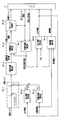
- FIG. 1 is a configuration diagram illustrating an outline of an engine control system according to an embodiment of the present disclosure.
- FIG. 2 is a functional block diagram showing engine control based on torque.
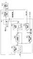
- FIG. 3 is a functional block diagram showing EGR-related control at the time of introduction of EGR gas.
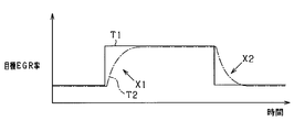
- FIG. 4 is a time chart showing the delay of the actual EGR rate with respect to the target EGR rate.
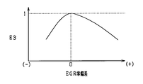
- FIG. 5 is a diagram showing the relationship between the EGR rate deviation and the EGR efficiency.
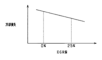
- FIG. 6 is a diagram showing the relationship between the EGR rate and the cooling loss in the engine heat account,
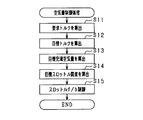
- FIG. 7 is a flowchart showing the air amount control.
- FIG. 8 is a flowchart showing the EGR control.
- a multi-cylinder four-cycle gasoline engine mounted on a vehicle is controlled, and electronic control of various actuators in the engine is performed.
- the multi-cylinder four-cycle gasoline engine corresponds to an internal combustion engine, and is referred to as the engine 10.
- an air flow meter 12 for detecting an intake air amount is provided upstream of the intake pipe 11.
- a throttle valve 14 whose opening degree is adjusted by a throttle actuator 13 such as a DC motor is provided on the downstream side of the air flow meter 12.
- the opening degree of the throttle valve 14 is detected by a throttle opening degree sensor 15 built in the throttle actuator 13.
- the opening degree of the throttle valve 14 is referred to as a throttle opening degree.
- a surge tank 16 is provided on the downstream side of the throttle valve 14, and an intake manifold 17 that is connected to an intake port of each cylinder is attached to the surge tank 16.
- the intake port and the exhaust port of the engine 10 are provided with an intake valve and an exhaust valve (both not shown), respectively.
- the engine 10 is provided with an intake side valve mechanism 21 that changes the opening / closing timing of the intake valve and an exhaust side valve mechanism 22 that changes the opening / closing timing of the exhaust valve. Further, the engine 10 is provided with a fuel injection valve 23 and a spark plug 24 for each cylinder.
- An exhaust manifold 25 is connected to the exhaust port of the engine 10, and an exhaust pipe 26 is connected to a collective portion of the exhaust manifold 25.
- the exhaust pipe 26 is provided with a catalyst 28 for purifying harmful components in the exhaust.
- a three-way catalyst that purifies three components of CO, HC, and NOx is used as the catalyst 28.
- An air-fuel ratio sensor 29 is provided on the upstream side of the catalyst 28 to detect the air-fuel ratio or oxygen concentration of the air-fuel mixture using exhaust as a detection target.
- a turbocharger 30 serving as a supercharger is provided between the intake pipe 11 and the exhaust pipe 26.
- the turbocharger 30 includes an intake compressor 31 disposed on the upstream side of the throttle valve 14 in the intake pipe 11, an exhaust turbine 32 disposed on the upstream side of the catalyst 28 in the exhaust pipe 26, and the intake compressor 31 and the exhaust turbine 32.
- the rotating shaft 33 to be connected is provided.
- the intake compressor 31 is rotated with the rotation of the exhaust turbine 32, and the intake air is compressed by the centrifugal force generated by the rotation of the intake compressor 31. . In this case, the intake air is supercharged.
- the intake pipe 11 is provided with an intercooler 34 as a heat exchanger for cooling the supercharged intake air on the downstream side of the throttle valve 14, and the intake air is cooled by the intercooler 34. A decrease in air charging efficiency is suppressed.
- the intercooler 34 is, for example, a water-cooled intake air cooling unit.
- the intercooler 34 is provided integrally with the surge tank 16, but the intercooler 34 may be provided upstream of the surge tank 16 or upstream of the throttle valve 14.
- the engine 10 is provided with an external EGR device 35 that introduces a part of the exhaust gas as EGR gas to the intake side.
- the EGR device 35 includes an EGR pipe 36 that connects the intake pipe 11 and the exhaust pipe 26, an electromagnetically driven EGR valve 37 that adjusts the amount of EGR gas flowing through the EGR pipe 36, and an EGR cooler 38 that cools the EGR gas. And have.
- the EGR cooler 38 is, for example, a water-cooled EGR cooling unit.
- the EGR pipe 36 is provided so as to connect the downstream side of the exhaust turbine 32 in the exhaust pipe 26 and the upstream side of the intake compressor 31 in the intake pipe 11, whereby a low-pressure loop type (LPL type) EGR system is provided. Build up.
- the EGR pipe 36 is provided so as to connect the downstream side of the catalyst 28 in the exhaust pipe 26.
- the present system includes a crank angle sensor 41 that outputs a crank angle signal for each predetermined crank angle of the engine 10, a water temperature sensor 42 that detects the coolant temperature of the engine 10, and an accelerator sensor 43 that detects the amount of accelerator operation by the driver.
- a crank angle sensor 41 that outputs a crank angle signal for each predetermined crank angle of the engine 10
- a water temperature sensor 42 that detects the coolant temperature of the engine 10
- an accelerator sensor 43 that detects the amount of accelerator operation by the driver.
- Various sensors such as are provided.
- the ECU 50 is configured mainly by a microcomputer 51 including a CPU, ROM, RAM, and the like as is well known, and executes various controls of the engine 10 by executing various control programs stored in the ROM.
- the microcomputer 51 receives detection signals and the like from the various sensors described above, and based on the input detection signals and the like, the throttle valve 14, the fuel injection valve 23, the ignition plug 24, the EGR valve 37, and the like. Control the drive.
- engine control based on torque is performed, and the microcomputer 51 controls the air amount by adjusting the opening of the throttle valve 14 or fuel injection according to the required torque requested by the user who is the driver.
- the amount control, ignition timing control, and EGR rate control are appropriately performed.
- the microcomputer 51 calculates a target throttle opening that is an air amount control parameter as an air amount control function, and controls the intake air amount of the engine 10 based on the target throttle opening.
- the microcomputer 51 includes a control parameter calculation unit that calculates a target throttle opening, and an air amount control unit that controls the intake air amount of the engine 10 based on the target throttle opening.
- the microcomputer 51 controls the flow rate of EGR gas recirculated from the exhaust side to the intake side based on the engine operating state as an EGR control function.
- the torque-based control includes control of the opening / closing timing of the intake valve and the exhaust valve, but the description is omitted in this embodiment.
- the microcomputer 51 constitutes a torque control unit and an EGR control unit.
- FIG. 2 is a functional block diagram showing engine control based on torque. Each function shown in FIG. 2 is realized by the microcomputer 51 of the ECU 50.
- the required torque of the engine 10 is calculated based on, for example, the engine speed NE and the accelerator operation amount.
- the torque correction unit M11 performs various corrections on the required torque to calculate the target torque.
- the target torque is calculated by correcting the engine loss and various kinds of efficiency.
- the engine loss correction for example, torque correction based on pump loss and friction loss is performed.
- the efficiency correction ignition efficiency correction based on the ignition timing and air-fuel ratio efficiency correction based on the actual air-fuel ratio are performed.
- the ignition efficiency calculation unit M12 calculates the amount of retardation of the actual ignition timing with respect to the ignition timing (MBT) at the maximum torque point, and calculates the ignition efficiency E1 based on the amount of retardation. .
- the air-fuel ratio efficiency calculation unit M13 calculates the air-fuel ratio efficiency E2 based on the target air-fuel ratio each time.
- the ignition efficiency E1 is calculated so as to be smaller as the retardation amount of the actual ignition timing with respect to MBT is larger.
- the air-fuel ratio efficiency E2 is larger as the air-fuel ratio is larger than the predetermined rich air-fuel ratio and the absolute value of the deviation is larger. , Calculated to be a small value.
- the air-fuel ratio efficiency E2 becomes the maximum value. Note that the smaller the efficiency, the smaller the generated torque in the engine 10. Then, the torque correction unit M11 divides the required torque by the multiplication value of the ignition efficiency E1 and the air-fuel ratio efficiency E2, and calculates the target torque as a result.
- the target air amount calculation unit M14 calculates a target charge air amount based on the target torque using a predetermined charge air amount model.
- the target opening calculation unit M15 calculates a target throttle opening based on the target charging air amount and the estimated charging air amount calculated by the charging air amount estimation unit M17 using a predetermined intake system model.
- the throttle control unit M16 calculates a control duty for driving the throttle actuator 13 based on the target throttle opening and the actual throttle opening detected by the throttle opening sensor 15. The throttle actuator 13 is driven by this control duty to adjust the throttle opening, and the air amount is controlled accordingly.
- the filling air amount estimation unit M17 estimates the estimated filling air amount based on the actual throttle opening and the actual intake air amount detected by the air flow meter 12, using a predetermined intake system model.
- the ignition timing calculation unit M18 calculates the ignition timing based on the estimated charge air amount and the engine speed NE. Based on this ignition timing, the spark plug 24 is driven to ignite.
- the injection amount calculation unit M19 calculates the fuel injection amount based on the estimated charge air amount, the target air-fuel ratio, and the actual air-fuel ratio detected by the air-fuel ratio sensor 29.
- the injection amount calculation unit M19 calculates the fuel injection amount by performing air-fuel ratio feedback control so that the actual air-fuel ratio matches the target air-fuel ratio.
- the fuel injection valve 23 is driven based on this fuel injection amount.
- the required torque efficiency is further corrected based on the EGR rate of the external EGR device 35, and the air amount control that reflects the EGR is performed. The details will be described below.
- FIG. 3 is a functional block diagram showing EGR-related control when EGR gas is introduced.
- FIG. 3 shows an EGR control unit M20.
- the torque correction unit M11, the target air amount calculation unit M14, and the target opening calculation unit M15 in the figure are the same as those shown in FIG.
- Each function shown in FIG. 3 is realized by the microcomputer 51 of the ECU 50 as in FIG.
- the target EGR rate calculation unit M21 calculates the target EGR rate (T1) based on the air amount and the engine speed NE that are load parameters.
- the target charge air amount calculated by the target air amount calculation unit M14 is used as a load parameter.
- the target EGR rate is calculated based on the target charge air amount and the engine rotational speed NE using a map that defines the relationship among the target charge air amount, the engine rotational speed NE, and the target EGR rate.
- the target EGR rate calculation unit M21 is a target EGR rate setting unit.
- the response limiting unit M22 limits the response of the target EGR rate based on a response delay until the EGR gas that has passed through the EGR valve 37 flows into the engine cylinder. At this time, the response limit is performed on the target EGR rate using an air model that simulates the behavior related to the inflow of the EGR gas into the cylinder, and the actual EGR rate (T2) at the time when the EGR gas flows into the cylinder is calculated. . Thereby, the EGR rate in accordance with the actual change is calculated.
- the air model was constructed based on a response delay from when the EGR valve 37 opening degree change was commanded to when the EGR gas increased or decreased by the EGR opening change was sucked into the cylinder (combustion chamber).
- the air model is expressed as a first-order lag model with a time constant T [s] and a dead time L [s], and the transfer function k is expressed by the following equation (1).
- k 1 / (T + 1) ⁇ e ⁇ L (1)
- T1 the target EGR rate without response limitation
- T2 the target EGR rate with response limitation
- the target EGR rate with response restriction is an actual EGR rate.
- T1 increases and changes like a rising edge
- T2 increases and changes with a predetermined delay due to response limitation.
- T1 decreases and changes like a falling edge
- T2 decreases and changes with a predetermined delay due to response limitation.
- the EGR efficiency calculation unit M23 inputs a deviation between the target EGR rate whose response is limited by the response limiting unit M22 and the target EGR rate which is not response-limited, and calculates the EGR efficiency E3 based on the EGR rate deviation. .
- the deviation removes the target EGR rate without response limitation from the target EGR rate with response limitation.
- the EGR efficiency calculation unit M23 calculates the EGR efficiency E3 based on the deviation (T2-T1) between the target EGR rate without response limitation T1 and the target EGR rate with response limitation T2 .
- the EGR efficiency E3 is a correction parameter for correcting the influence on the torque accompanying the introduction of EGR gas.
- the EGR efficiency calculation unit M23 corresponds to a correction parameter calculation unit.
- the deviation is an EGR rate deviation.
- the EGR efficiency calculation unit M23 calculates the EGR efficiency E3 using the relationship shown in FIG. In FIG. 5, when the EGR rate deviation is 0 or in the vicinity of 0, the relationship is set such that the EGR efficiency E3 is 1, and the EGR efficiency E3 is reduced as the absolute value of the EGR rate deviation increases. In this case, the torque increase correction amount is increased.
- FIG. 6 shows the relationship between the EGR rate and the cooling loss in the heat account of the engine 10. According to FIG. 6, for example, when the EGR rate is 0% and 25%, the cooling loss is smaller at 25%. That is, the greater the degree of decrease in the actual EGR rate with respect to the target value, the greater the decrease in cooling loss.
- the EGR rate deviation is positive, that is, when T2 becomes larger than T1 due to the target EGR rate decreasing and changing as indicated by X2 in FIG. 4, the actual EGR rate is less than the target value.
- the combustion state deteriorates due to the increase, and therefore the EGR efficiency E3 is lowered. That is, the EGR efficiency E3 is calculated by reflecting that the combustion of the engine 10 deteriorates.
- the slope (change rate) of the EGR efficiency on the vertical axis with respect to the EGR rate deviation on the horizontal axis may be different between the positive and negative cases of the EGR rate deviation.
- the slope may be larger than when the is negative, or vice versa.
- the EGR efficiency calculated by the EGR efficiency calculation unit M23 is used for torque correction by the torque correction unit M11. That is, the torque correction unit M11 divides the required torque by the multiplication value of the ignition efficiency E1, the air-fuel ratio efficiency E2, and the EGR efficiency E3, and calculates the target torque as a result. As a result, appropriate air amount control can be performed while taking into account the effects of ignition timing, air-fuel ratio, and EGR on torque.
- the target EGR opening degree calculation unit M24 calculates a target EGR opening degree that is a target value of the opening degree of the EGR valve 37 based on the target EGR rate. Specifically, the target EGR opening is calculated based on the target EGR rate using a map that defines the relationship between the target EGR rate and the target EGR opening. Then, the EGR valve 37 is driven based on the target EGR opening, and the EGR gas amount is adjusted accordingly. At this time, the EGR valve 37 does not add an EGR response and is immediately controlled according to the target EGR rate.
- the EGR rate when the EGR gas flows into the cylinder A certain actual EGR rate is calculated.
- response restriction is performed on the target EGR opening using an air model that simulates the behavior related to in-cylinder inflow of EGR gas, and the actual EGR rate is calculated.
- the air model used in the actual EGR rate calculation unit M25 may be the same as the air model used in the response limiting unit M22, and is expressed as a first-order lag model.
- the actual EGR rate calculated by the actual EGR rate calculation unit M25 is used for calculation of the target throttle opening by the target opening calculation unit M15.
- the target throttle opening can be appropriately calculated while taking into account the EGR response when the EGR gas is introduced.
- the microcomputer 51 calculates the required torque of the engine 10 based on the engine speed NE and the accelerator operation amount.
- the microcomputer 51 performs various corrections related to engine loss and efficiency with respect to the required torque, and calculates a target torque. At this time, the correction based on the ignition efficiency E1, the air-fuel ratio efficiency E2, and the EGR efficiency E3 is performed regarding the efficiency correction.
- the microcomputer 51 calculates a target charged air amount based on the target torque using the charged air amount model.
- the microcomputer 51 uses the intake system model to calculate the target throttle opening based on the target charge air amount, the actual charge air amount, and the actual EGR rate.
- the actual charge air amount is an estimated charge air amount estimated from the actual throttle opening and the actual intake air amount.
- the microcomputer 51 performs feedback control of the throttle opening based on the target throttle opening and the actual throttle opening.
- the microcomputer 51 calculates the target EGR rate T1 based on the target charge air amount and the engine rotational speed NE.
- the microcomputer 51 performs the response limitation of the target EGR rate T1 based on the delay of the EGR valve response, and calculates the target EGR rate T2 with response limitation.
- the microcomputer 51 calculates the EGR efficiency E3 based on the EGR rate deviation.
- the microcomputer 51 calculates the target EGR opening based on the target EGR rate calculated in S21.
- the microcomputer 51 controls the EGR opening degree. In this case, the EGR valve 37 is driven based on the target EGR opening, and the EGR gas amount is adjusted accordingly.
- the microcomputer 51 calculates the actual EGR rate based on the target EGR opening degree and the delay of the EGR response.
- the EGR efficiency E3 which is a correction parameter for torque correction
- the EGR efficiency E3 is calculated based on the deviation between the target EGR rate T2 with response limitation and the target EGR rate T1 without response limitation.
- torque control can be performed in consideration of changes in torque loss and changes in combustion state accompanying the introduction of EGR gas.
- the target EGR rate changes transient
- torque correction is performed in consideration of the response delay of the actual EGR rate with respect to the change in the target EGR rate. For this reason, it is possible to appropriately cope with the transient response when the EGR gas is introduced.
- high accuracy and stabilization of torque control at the time of introduction of EGR gas can be realized.
- an air flow meter 12 is used to detect the change in intake air amount associated with the introduction of EGR gas.
- the actual EGR rate is estimated based on the actual intake air amount, and torque correction is performed based on the estimated value of the actual EGR rate.
- a feedback loop of calculation having acquisition of the actual intake air amount, estimation of the actual EGR rate, torque correction, and control of the intake air amount is formed, and the feedback loop may cause system divergence. For example, when the actual intake air amount increases, the estimated value of the actual EGR rate decreases, and the intake air amount is controlled to increase to compensate for the increase in cooling loss caused by the decrease in the actual EGR rate.
- the system diverges and the control becomes unstable.
- the response limitation of the target EGR rate is performed to cope with the delay of the EGR response, the feedback loop can be eliminated regarding the torque correction based on the EGR rate. As a result, the system can be stabilized.
- the EGR efficiency E3 is calculated such that the greater the deviation between the response-limited target EGR rate T2 and the non-response-limited target EGR rate T1, the greater the torque increase correction. Therefore, torque correction can be performed in consideration of the degree of EGR response delay.
- the EGR efficiency E3 is calculated to reflect the increase in the cooling loss of the internal combustion engine, and the target whose response is not limited
- the EGR efficiency E3 is calculated by reflecting that the combustion of the internal combustion engine is deteriorated due to excessive EGR (see FIG. 5). Therefore, appropriate transient response control can be performed in both cases where the target EGR rate increases and decreases.
- the target EGR opening is calculated from the target EGR rate, and the EGR valve 37 is controlled by the target EGR opening, while the actual EGR rate is calculated by reflecting the EGR response in the target EGR opening, and the actual EGR rate is used.
- the target throttle opening was calculated. In this case, the operation of the EGR valve 37 is controlled without adding an EGR response, so that a quick transient response can be realized when the EGR valve 37 is operating.
- the actual EGR rate is calculated by reflecting the EGR response in the target EGR opening, and the throttle opening is controlled using the actual EGR rate. Therefore, the amount of EGR gas actually flowing into the engine cylinder is reflected. However, the air amount control can be properly performed.
- the target throttle opening as the air amount control parameter is calculated based on the actual EGR rate calculated by limiting the target EGR opening, but this is changed to the actual EGR rate. Based on this, the target charge air amount as the air amount control parameter may be calculated.
- an HPL (high-pressure loop) EGR system may be used as an external EGR system.
- an EGR pipe is provided so as to connect the upstream side of the exhaust turbine 32 in the exhaust pipe 26 and the downstream side of the intake compressor 31 in the intake pipe 11. In this case as well, as described above, torque correction based on EGR efficiency may be performed.
- the present disclosure can be applied to an internal combustion engine other than a gasoline engine, for example, a diesel engine.
Landscapes
- Engineering & Computer Science (AREA)
- Chemical & Material Sciences (AREA)
- Combustion & Propulsion (AREA)
- Mechanical Engineering (AREA)
- General Engineering & Computer Science (AREA)
- Output Control And Ontrol Of Special Type Engine (AREA)
- Exhaust-Gas Circulating Devices (AREA)
- Control Of Vehicle Engines Or Engines For Specific Uses (AREA)
Abstract
ECU(50)は、ユーザの要求に応じて定められる要求トルクに基づいて、エンジン(10)で生成されるトルクを制御するとともに、EGR配管(36)に設けられたEGR弁(37)を駆動し、EGR配管(36)を介して排気側から吸気側に還流されるEGRガスの流量を制御する。ECU(50)は、エンジン(10)における目標EGR率を設定するとともに、EGR弁(37)を通過したEGRガスがエンジン(10)の筒内に流入するまでの応答の遅れに基づいて目標EGR率を応答制限する。そして、ECU(50)は、応答制限した目標EGR率と、応答制限していない目標EGR率との偏差に基づいて、EGRガスの導入に伴うトルクへの影響分を補正する補正パラメータを算出し、その補正パラメータにより要求トルクの補正を実施する。
Description
本開示は、2014年3月7日に出願された日本出願番号2014-45184号に基づくもので、ここにその記載内容を援用する。
本開示は、内燃機関の制御装置に関するものである。
車載内燃機関の制御に関する技術として、運転者が要求する要求トルクをベースにして各種アクチュエータの駆動を制御する、いわゆるトルクベース制御が知られている。トルクベース制御では、運転者によるアクセル操作量及びその時の内燃機関の運転状態に基づいて要求トルクを算出するとともに、その要求トルクに対して、ポンプ損失、摩擦損失といったエンジンロスを加算して目標トルクを算出する。そして、その目標トルクを実現するべく、スロットル調整装置、噴射装置、点火装置等の各種アクチュエータの動作を制御する。
また、例えば特許文献1には、複数のアクチュエータを協働させて筒内の空気量及びEGR率を調整する技術が開示されている。かかる技術について具体的には、EGRがトルクに与える影響を補正する補正係数を、目標EGR率と現時点における空気量の実値又は推定値とに基づいて算出するとともに、その補正係数で目標トルクを補正して得られる値から目標空気量を算出し、さらに目標空気量と目標EGR率とに基づいて、複数のアクチュエータのそれぞれの動作を制御する。
ところで、外部EGR装置を用いた構成では、目標EGR率に相当する量のEGRガスを導入すべくEGR弁を動作させても、そのEGR弁の開度変化分のEGRガスが実際に内燃機関の筒内に吸入されるまでにはガス輸送等の時間を要する。つまり、EGRガスの導入に関して過渡応答の遅れが生じる。この点、上記従来技術は、EGRの影響を受けないようにトルク制御を実施しようとするものであるが、未だ改善の余地がある。
本開示は、EGRガスの導入時におけるトルク制御の高精度化や安定化を実現することができる内燃機関の制御装置を提供することを目的とする。
本開示における内燃機関の制御装置は、ユーザの要求に応じて定められる要求トルクに基づいて、内燃機関で生成されるトルクを制御するトルク制御部と、EGR配管に設けられたEGR弁を駆動し、前記EGR配管を介して排気側から吸気側に還流されるEGRガスの流量を制御するEGR制御部とを備える。そして、内燃機関の制御装置は、前記内燃機関におけるEGR率の目標値である目標EGR率を設定する目標EGR率設定部と、前記EGR弁を通過したEGRガスが前記内燃機関の筒内に流入するまでの応答の遅れに基づいて前記目標EGR率を応答制限する応答制限部と、前記応答制限部により応答制限した前記目標EGR率と、応答制限していない前記目標EGR率との偏差に基づいて、EGRガスの導入に伴うトルクへの影響分を補正する補正パラメータを算出する補正パラメータ算出部と、前記補正パラメータ算出部により算出した補正パラメータにより前記要求トルクの補正を実施するトルク補正部と、を備える。
上記構成では、内燃機関の制御装置、要求トルクの補正に際し、応答制限有りの目標EGR率と応答制限無しの目標EGR率との偏差に基づいて、トルク補正の補正パラメータを算出することとしており、EGRガスの導入に伴うトルク損失の変化や燃焼状態の変化を加味してトルク制御を実施できる。この場合、目標EGR率の変化時(過渡時)には、その目標EGR率の変化に対する実際のEGR率の応答遅れを考慮してトルク補正が実施される。そのため、EGRガスの導入時において過渡応答に対する適切な対応が可能となる。以上により、EGRガスの導入時におけるトルク制御の高精度化や安定化を実現することができる。
本開示についての上記目的およびその他の目的、特徴や利点は、添付の図面を参照しながら下記の詳細な記述により、より明確になる。その図面は、
図1は、本開示の一実施形態におけるエンジン制御システムの概略を示す構成図であり、
図2は、トルクベースによるエンジン制御を示す機能ブロック図であり、
図3は、EGRガスの導入時におけるEGR関連の制御を示す機能ブロック図であり、
図4は、目標EGR率に対する実際のEGR率の遅れを示すタイムチャートであり、
図5は、EGR率偏差とEGR効率との関係を示す図であり、
図6は、エンジン熱勘定においてEGR率と冷却損失との関係を示す図であり、
図7は、空気量制御を示すフローチャートであり、
図8は、EGR制御を示すフローチャートである。
以下、本開示を具体化した一実施形態を図面に基づいて説明する。本実施形態は、車両に搭載される多気筒4サイクルガソリンエンジンを制御対象とし、当該エンジンにおける各種アクチュエータの電子制御を実施する。本実施形態では、多気筒4サイクルガソリンエンジンは内燃機関に相当し、エンジン10とする。まず、図1によりエンジン制御システムの全体概略構成を説明する。
図1に示すエンジン10において、吸気管11の上流部には吸入空気量を検出するエアフロメータ12が設けられている。エアフロメータ12の下流側には、DCモータ等のスロットルアクチュエータ13によって開度調節されるスロットル弁14が設けられている。スロットル弁14の開度はスロットルアクチュエータ13に内蔵されたスロットル開度センサ15により検出される。この場合、スロットル弁14の開度はスロットル開度と呼ぶ。スロットル弁14の下流側にはサージタンク16が設けられ、サージタンク16には、各気筒の吸気ポートに通じる吸気マニホールド17が取り付けられている。
エンジン10の吸気ポート及び排気ポートには、それぞれ吸気弁及び排気弁(共に図示略)が設けられている。エンジン10には、吸気弁の開閉タイミングを変化させる吸気側動弁機構21と、排気弁の開閉タイミングを変化させる排気側動弁機構22とが設けられている。また、エンジン10には気筒ごとに燃料噴射弁23と点火プラグ24とが設けられている。
エンジン10の排気ポートには排気マニホールド25が接続され、その排気マニホールド25の集合部に排気管26が接続されている。排気管26には、排気中の有害成分を浄化する触媒28が設けられている。本実施形態では、触媒28としてCO、HC、NOxの三成分を浄化する三元触媒が用いられている。触媒28の上流側には、排気を検出対象として混合気の空燃比または酸素濃度を検出する空燃比センサ29が設けられている。
吸気管11と排気管26との間には、過給機としてのターボチャージャ30が設けられている。ターボチャージャ30は、吸気管11においてスロットル弁14の上流側に配置された吸気コンプレッサ31と、排気管26において触媒28の上流側に配置された排気タービン32と、吸気コンプレッサ31及び排気タービン32を連結する回転軸33とを備えて構成されている。ターボチャージャ30において、排気管26を流れる排気によって排気タービン32が回転されると、排気タービン32の回転に伴い吸気コンプレッサ31が回転され、吸気コンプレッサ31の回転により生じる遠心力によって吸気が圧縮される。この場合、吸気が過給される。
また、吸気管11には、スロットル弁14の下流側に、過給された吸気を冷却する熱交換器としてのインタークーラ34が設けられており、このインタークーラ34により吸気が冷却されることで空気の充填効率の低下が抑制される。インタークーラ34は例えば水冷式の吸気冷却部である。本実施形態では、サージタンク16に一体にインタークーラ34が設けられるが、サージタンク16の上流側又はスロットル弁14の上流側にインタークーラ34が設けられる構成であってもよい。
また、エンジン10には、排気の一部をEGRガスとして吸気側に導入する外部EGR装置35が設けられている。このEGR装置35は、吸気管11と排気管26とを接続するEGR配管36と、EGR配管36を流れるEGRガス量を調節する電磁駆動式のEGR弁37と、EGRガスを冷却するEGRクーラ38とを有する。EGRクーラ38は例えば水冷式のEGR冷却部である。EGR配管36は、排気管26において排気タービン32の下流側と、吸気管11において吸気コンプレッサ31の上流側とを接続するように設けられており、これにより低圧ループ方式(LPL方式)のEGRシステムを構築する。本実施形態では、EGR配管36は、排気管26において触媒28の下流側とを接続するように設けられている。
その他、本システムには、エンジン10の所定クランク角ごとにクランク角信号を出力するクランク角センサ41、エンジン10の冷却水温度を検出する水温センサ42、ドライバによるアクセル操作量を検出するアクセルセンサ43等の各種センサが設けられている。
ECU50は、周知の通りCPU、ROM、RAM等よりなるマイクロコンピュータ51を主体として構成され、ROMに記憶された各種の制御プログラムを実行することで、エンジン10の各種制御を実施する。具体的には、マイクロコンピュータ51は、前述した各種センサから検出信号等を入力し、その入力した検出信号等に基づいて、スロットル弁14や、燃料噴射弁23、点火プラグ24、EGR弁37等の駆動を制御する。
本実施形態では、トルクベースによるエンジン制御を実施することとしており、マイクロコンピュータ51は、ドライバであるユーザが要求する要求トルクに応じて、スロットル弁14の開度調節による空気量制御や、燃料噴射量の制御、点火時期の制御、EGR率の制御を適宜実施する。これにより、エンジン10で生成されるトルクが制御される。この場合特に、マイクロコンピュータ51は、空気量制御機能として、空気量制御パラメータである目標スロットル開度を算出するとともに、その目標スロットル開度に基づいてエンジン10の吸入空気量を制御する。本実施形態では、マイクロコンピュータ51は、目標スロットル開度を算出する制御パラメータ算出部と、その目標スロットル開度に基づいてエンジン10の吸入空気量を制御する空気量制御部を有する。また、マイクロコンピュータ51は、EGR制御機能として、エンジン運転状態に基づいて、排気側から吸気側に還流されるEGRガスの流量を制御する。なお、トルクベースによる制御としては上記以外に、吸気弁や排気弁についての開閉タイミングの制御等があるが、本実施形態では説明を割愛する。本実施形態では、マイクロコンピュータ51によりトルク制御部及びEGR制御部が構成されている。
図2は、トルクベースによるエンジン制御を示す機能ブロック図である。図2に示す各機能はECU50のマイクロコンピュータ51により実現される。
図2において、エンジン10の要求トルクは、例えばエンジン回転速度NEやアクセル操作量に基づいて算出される。そして、トルク補正部M11では、要求トルクに対して各種の補正を行い目標トルクを算出する。このトルク補正部M11では、エンジンロス分の補正や各種の効率による補正を実施して目標トルクを算出する。エンジンロス補正としては、例えばポンプ損失、摩擦損失に基づくトルク補正が実施される。また、効率補正としては、点火時期に基づく点火効率補正や、実空燃比に基づく空燃比効率補正が実施される。
ここで、点火時期に関しては、点火効率算出部M12において、トルク最大点における点火時期(MBT)に対する実点火時期の遅角量を算出するとともに、その遅角量に基づいて点火効率E1を算出する。また、実空燃比に関しては、空燃比効率算出部M13において、都度の目標空燃比に基づいて空燃比効率E2を算出する。点火効率E1は、MBTに対する実点火時期の遅角量が大きいほど、小さい値になるようにして算出され、空燃比効率E2は、空燃比が所定のリッチ空燃比と偏差の絶対値が大きくなるほど、小さい値になるようにして算出される。つまり、空燃比が所定のリッチ空燃比の場合、空燃比効率E2が最大値となる。なお、効率が小さいほど、エンジン10での生成トルクが小さくなる。そして、トルク補正部M11では、要求トルクを、点火効率E1と空燃比効率E2との乗算値により除算し、その結果として目標トルクを算出する。
目標空気量算出部M14では、あらかじめ定められた充填空気量モデルを用い、目標トルクに基づいて目標充填空気量を算出する。目標開度算出部M15では、あらかじめ定められた吸気系モデルを用い、目標充填空気量と、充填空気量推定部M17で算出した推定充填空気量とに基づいて目標スロットル開度を算出する。さらに、スロットル制御部M16では、目標スロットル開度と、スロットル開度センサ15により検出される実スロットル開度とに基づいて、スロットルアクチュエータ13を駆動させる制御デューティを算出する。この制御デューティによりスロットルアクチュエータ13が駆動されてスロットル開度が調整され、それに伴い空気量が制御される。
また、充填空気量推定部M17では、あらかじめ定められた吸気系モデルを用い、実スロットル開度と、エアフロメータ12により検出される実吸入空気量とに基づいて、推定充填空気量を推定する。
その他に、点火時期算出部M18では、推定充填空気量とエンジン回転速度NEとに基づいて点火時期を算出する。この点火時期に基づいて点火プラグ24が点火駆動される。噴射量算出部M19では、推定充填空気量と目標空燃比と空燃比センサ29により検出される実空燃比とに基づいて燃料噴射量を算出する。噴射量算出部M19では、実空燃比を目標空燃比に一致させるよう空燃比フィードバック制御を実施して燃料噴射量を算出する。この燃料噴射量に基づいて燃料噴射弁23が駆動される。
また、本実施形態のシステムでは、上記トルクベースによるエンジン制御において、さらに外部EGR装置35のEGR率に基づいて要求トルクの効率補正を実施するとともに、EGRの実施を反映した空気量制御を実施することとしており、以下にその詳細を説明する。
図3は、EGRガスの導入時におけるEGR関連の制御を示す機能ブロック図である。図3は、EGR制御部M20を示すものであり、図中のトルク補正部M11や、目標空気量算出部M14、目標開度算出部M15は図2に示すものと同一である。図3に示す各機能は、図2と同様、ECU50のマイクロコンピュータ51により実現される。
図3のEGR制御部M20において、目標EGR率算出部M21では、負荷パラメータである空気量やエンジン回転速度NEに基づいて目標EGR率(T1)を算出する。本実施形態では、目標空気量算出部M14により算出した目標充填空気量を負荷パラメータとしている。具体的には、目標充電空気量とエンジン回転速度NEと目標EGR率との関係を定めたマップを用い、目標充電空気量とエンジン回転速度NEとに基づいて目標EGR率を算出する。本実施形態では、目標EGR率算出部M21は目標EGR率設定部である。
また、応答制限部M22では、EGR弁37を通過したEGRガスがエンジン気筒内に流入するまでの応答の遅れに基づいて、目標EGR率の応答制限を実施する。このとき、目標EGR率に対して、EGRガスの筒内流入に関する挙動を模擬したエアモデルを用いて応答制限を行い、EGRガスが筒内に流入する時点における実際のEGR率(T2)を算出する。これにより、実際の変化に即したEGR率が算出される。エアモデルは、EGR弁37の開度変更が指令されてから、そのEGR開度の変更により増量又は減量されたEGRガスが筒内(燃焼室内)に吸入されるまでの応答遅れに基づき構築されたものであり、EGR弁37の応答遅れや、EGR配管36及び吸気管11におけるEGRガスの輸送遅れが考慮された。本実施形態では、エアモデルは、時定数T〔s〕、無駄時間L〔s〕の一次遅れモデルとして表現され、伝達関数kを下記の数式(1)で表れる。
k=1/(T+1)×e-L …(1)
目標EGR率が応答制限された場合には、目標EGR率に過渡変化が生じる際に遅れが付与される。これを図4により説明する。なお図4でも、応答制限無しの目標EGR率をT1、応答制限有りの目標EGR率をT2としている。本実施形態では、応答制限有りの目標EGR率は実際のEGR率である。図4に示すように、目標EGR率が増加する場合、T1が立ち上がりエッジのように増加変化するのに対し、T2が応答制限により所定の遅れを伴いながら増加変化する。また、目標EGR率が減少する場合、T1が立下りエッジのように減少変化するのに対し、T2が応答制限により所定の遅れを伴いながら減少変化する。
k=1/(T+1)×e-L …(1)
目標EGR率が応答制限された場合には、目標EGR率に過渡変化が生じる際に遅れが付与される。これを図4により説明する。なお図4でも、応答制限無しの目標EGR率をT1、応答制限有りの目標EGR率をT2としている。本実施形態では、応答制限有りの目標EGR率は実際のEGR率である。図4に示すように、目標EGR率が増加する場合、T1が立ち上がりエッジのように増加変化するのに対し、T2が応答制限により所定の遅れを伴いながら増加変化する。また、目標EGR率が減少する場合、T1が立下りエッジのように減少変化するのに対し、T2が応答制限により所定の遅れを伴いながら減少変化する。
そして、EGR効率算出部M23では、応答制限部M22により応答制限した目標EGR率と、応答制限していない目標EGR率との偏差を入力し、そのEGR率偏差に基づいてEGR効率E3を算出する。本実施形態では、上記偏差は応答制限有りの目標EGR率から応答制限無しの目標EGR率を取り去る。図3では、EGR効率算出部M23において、応答制限無しの目標EGR率であるT1と、応答制限有りの目標EGR率であるT2との偏差(T2-T1)に基づいてEGR効率E3を算出する。このEGR効率E3は、EGRガスの導入に伴うトルクへの影響分を補正する補正パラメータであり、本実施形態では、EGR効率算出部M23が補正パラメータ算出部に相当する。さらに、上記偏差はEGR率偏差である。
具体的には、EGR効率算出部M23では、図5に示す関係を用いてEGR効率E3を算出する。図5では、EGR率偏差が0又は0付近の場合に、EGR効率E3を1とし、EGR率偏差の絶対値が大きくなるほどEGR効率E3を小さい値にするような関係が定められている。この場合、トルク増補正分を大きくする。
より詳しくは、EGR率偏差が負である場合、すなわち図4のX1のように目標EGR率が増加変化することでT2がT1より小さくなる場合には、目標値に対して実際のEGR率が小さくなっていることに起因してエンジン10での冷却損失が大きくなり、故にEGR効率E3を低下させている。つまり、エンジン10の冷却損失が増加することを反映させてEGR効率E3を算出する。ちなみに図6には、エンジン10の熱勘定においてEGR率と冷却損失との関係を示す。図6によれば、例えばEGR率が0%の場合と25%の場合とを比較して、25%の方が冷却損失が小さくなっている。つまり、目標値に対する実際のEGR率の低下の度合いが大きいほど、冷却損失の低下が大きくなり易い。
また一方で、EGR率偏差が正である場合、すなわち図4のX2のように目標EGR率が減少変化することでT2がT1より大きくなる場合には、目標値に対して実際のEGR率が大きくなっていることに起因して燃焼状態の悪化が生じ、故にEGR効率E3を低下させている。つまり、エンジン10の燃焼が悪化することを反映させてEGR効率E3を算出する。
図5において、横軸のEGR率偏差に対する縦軸のEGR効率の傾き(変化率)については、EGR率偏差が正の場合と負の場合とで相違していてもよく、正の場合の方が負の場合よりの傾きを大きくしてもよいし、その逆であってもよい。なお、EGR効率E3を、目標EGR率の大きさに基づいて算出することも可能である。この場合、目標EGR率が大きいほど、EGR効率E3を小さい値にするとよい。
EGR効率算出部M23で算出したEGR効率は、トルク補正部M11でのトルク補正に用いられる。すなわち、トルク補正部M11では、要求トルクを、点火効率E1と空燃比効率E2とEGR効率E3との乗算値により除算し、その結果として目標トルクを算出する。これにより、点火時期、空燃比、EGRのそれぞれがトルクに及ぼす影響を加味しつつ、適正な空量制御が実施できることとなる。
また、目標EGR開度算出部M24では、目標EGR率に基づいて、EGR弁37の開度の目標値である目標EGR開度を算出する。具体的には、目標EGR率と目標EGR開度との関係を定めたマップを用い、目標EGR率に基づいて目標EGR開度を算出する。そして、この目標EGR開度に基づいてEGR弁37が駆動され、それに伴いEGRガス量が調整される。このとき、EGR弁37はEGR応答を付加せず、目標EGR率に応じて即座に制御される。
実EGR率算出部M25では、目標EGR開度と、EGR弁37を通過したEGRガスがエンジン気筒内に流入するまでの応答の遅れとに基づいて、EGRガスの筒内流入時のEGR率である実EGR率を算出する。このとき、目標EGR開度に対して、EGRガスの筒内流入に関する挙動を模擬したエアモデルを用いて応答制限を行い、実EGR率を算出する。なお、実EGR率算出部M25で用いられるエアモデルは、応答制限部M22で用いられるエアモデルと同じものであればよく、一次遅れモデルとして表現される。
実EGR率算出部M25で算出した実EGR率は、目標開度算出部M15での目標スロットル開度の算出に用いられる。これにより、EGRガスの導入時におけるEGR応答を考慮しつつ目標スロットル開度を適正に算出できることとなる。
次に、ECU50のマイクロコンピュータ51により実施される空気量制御と、EGR制御とについて図7及び図8のフローチャートを用いて説明する。これら各フローチャートに示す処理は、マイクロコンピュータ51により所定周期で繰り返し実施される。
まずは空気量制御を示す図7のフローチャートにおいて、S11では、マイクロコンピュータ51が、エンジン回転速度NEやアクセル操作量に基づいてエンジン10の要求トルクを算出する。S12では、マイクロコンピュータ51が、要求トルクに対して、エンジンロスや効率に関する各種補正を行い目標トルクを算出する。このとき、効率補正に関して、点火効率E1、空燃比効率E2、EGR効率E3に基づく補正が実施される。
その後、S13では、マイクロコンピュータ51が、充填空気量モデルを用い、目標トルクに基づいて目標充填空気量を算出する。S14では、マイクロコンピュータ51が、吸気系モデルを用い、目標充填空気量と実充填空気量と実EGR率とに基づいて目標スロットル開度を算出する。ここで、実充填空気量は実スロットル開度及び実吸入空気量から推定した推定充填空気量である。さらに、S15では、マイクロコンピュータ51が、目標スロットル開度と実スロットル開度とに基づいて、スロットル開度のフィードバック制御を実施する。
また、EGR制御を示す図8のフローチャートにおいて、S21では、マイクロコンピュータ51が、目標充填空気量やエンジン回転速度NEに基づいて目標EGR率T1を算出する。S22では、マイクロコンピュータ51が、EGR弁応答の遅れに基づいて、目標EGR率T1の応答制限を実施し、応答制限付きの目標EGR率T2を算出する。そして、S23では、マイクロコンピュータ51が、応答制限していない目標EGR率T1と、応答制限した目標EGR率T2との偏差(=T2-T1)を算出する。S24では、マイクロコンピュータ51が、そのEGR率偏差に基づいてEGR効率E3を算出する。
また、S25では、マイクロコンピュータ51が、S21で算出した目標EGR率に基づいて、目標EGR開度を算出する。S26では、マイクロコンピュータ51が、EGR開度の制御を実施する。この場合、EGR弁37は、目標EGR開度に基づいて駆動され、それに伴いEGRガス量が調整される。S27では、マイクロコンピュータ51が、目標EGR開度とEGR応答の遅れとに基づいて、実EGR率を算出する。
以上詳述した本実施形態によれば、以下の優れた効果が得られる。
上記構成では、要求トルクの補正に際し、応答制限有りの目標EGR率T2と応答制限無しの目標EGR率T1との偏差に基づいて、トルク補正の補正パラメータであるEGR効率E3を算出することとしたため、EGRガスの導入に伴うトルク損失の変化や燃焼状態の変化を加味してトルク制御を実施できる。この場合、目標EGR率の変化時(過渡時)には、その目標EGR率の変化に対する実際のEGR率の応答遅れを考慮してトルク補正が実施される。そのため、EGRガスの導入時において過渡応答に対する適切な対応が可能となる。以上により、EGRガスの導入時におけるトルク制御の高精度化や安定化を実現することができる。
ちなみに、EGRガスの導入に伴うトルクへの影響分を補正する別の手法としては、EGRガスの導入に伴う吸入空気量の変化をモデル化した吸気系モデルを用いて、エアフロメータ12により検出される実吸入空気量に基づいて実EGR率を推定するとともに、その実EGR率の推定値に基づいてトルク補正を実施する。ただしかかる場合には、実吸入空気量の取得、実EGR率の推定、トルク補正、吸入空気量の制御を有する演算のフィードバックループが形成され、そのフィードバックループによってシステムの発散が生じるおそれがある。例えば、実吸入空気量が増加した場合には、実EGR率の推定値が低下し、実EGR率の低下に伴い生じる冷却損失の増加分を補うべく吸入空気量が増量制御される。実EGR率の低下と吸入空気量の増加により、システムの発散が生じて制御が不安定になる。この点、本実施形態では、目標EGR率の応答制限を行うことでEGR応答の遅れに対応させるようにしたため、EGR率に基づくトルク補正に関してフィードバックループを無くすことができる。これにより、システムの安定化を実現できる。
特に低圧ループ方式(LPL方式)のEGRシステムを用いる場合には、EGRの応答遅れが比較的大きいものとなり、トルク制御への影響が大きくなるが、こうしたシステムにおいても適正なトルク制御を実現できる。
図5に示すように、応答制限した目標EGR率T2と応答制限していない目標EGR率T1との偏差が大きいほど、トルク増補正分が大きくなるようにしてEGR効率E3を算出する。そのため、EGRの応答遅れの程度を加味してトルク補正を実施できる。
目標EGR率T1が増加側に変化する場合、及び減少側に変化する場合に、EGR率偏差(=T2-T1)が大きくなるほど小さくなるようにしてEGR効率E3を算出する。これにより、EGR過渡が生じる場合において適正なトルク制御を実施できる。
応答制限していない目標EGR率T1に対して応答制限した目標EGR率T2が小さい場合に、内燃機関の冷却損失が増加することを反映させてEGR効率E3を算出し、応答制限していない目標EGR率T1に対して応答制限した目標EGR率T2が大きい場合に、EGR過多による内燃機関の燃焼が悪化することを反映させてEGR効率E3を算出する(図5参照)。そのため、目標EGR率が増加変化する場合、減少変化する場合のいずれにおいても適正な過渡応答制御を実施できる。
目標EGR率から目標EGR開度を算出し、その目標EGR開度によりEGR弁37を制御する一方、目標EGR開度にEGR応答を反映して実EGR率を算出するとともに、その実EGR率を用いて目標スロットル開度を算出するようにした。この場合、EGR弁37の動作に関してはEGR応答を付加せずに制御が実施されるため、EGR弁37の動作時おいていち早い過渡応答を実現できる。また、目標EGR開度にEGR応答を反映することで実EGR率が算出され、その実EGR率を用いてスロットル開度が制御されるため、実際にエンジン気筒内に流入するEGRガス量を反映させつつ、空気量制御を適正に実施できる。
上記実施形態を例えば次のように変更してもよい。
(a)目標EGR率T1が増加側に変化すること、及び減少側に変化することをそれぞれ判定し、これらの変化が生じると判定された場合にのみ、EGR率偏差に基づくトルク補正を実施してもよい。
(b)上記実施形態では、目標EGR開度を応答制限して算出した実EGR率に基づいて、空気量制御パラメータとしての目標スロットル開度を算出するが、これを変更し、実EGR率に基づいて、空気量制御パラメータとしての目標充填空気量を算出してもよい。
(c)外部EGRシステムとして、HPL方式(高圧ループ方式)のEGRシステムを用いてもよい。このEGRシステムでは、排気管26において排気タービン32の上流側と、吸気管11において吸気コンプレッサ31の下流側とを接続するようにEGR配管が設けられる。この場合にも、上記同様、EGR効率に基づくトルク補正を実施するとよい。
(d)トルク補正として、上記以外に、吸気側動弁機構21による吸気弁の開閉タイミングに基づく効率補正や、排気側動弁機構22による排気弁の開閉タイミングに基づく効率補正を実施してもよい。
(e)本開示は、ガソリンエンジン以外の内燃機関にも適用可能であり、例えばディーゼルエンジンにも適用できる。
本開示は、実施例に準拠して記述されたが、本開示は当該実施例や構造に限定されるものではないと理解される。本開示は、様々な変形例や均等範囲内の変形をも包含する。加えて、様々な組み合わせや形態、さらには、それらに一要素のみ、それ以上、あるいはそれ以下、を含む他の組み合わせや形態をも、本開示の範疇や思想範囲に入るものである。
Claims (5)
- ユーザの要求に応じて定められる要求トルクに基づいて、内燃機関(10)で生成されるトルクを制御するトルク制御部(51)と、EGR配管(36)に設けられたEGR弁(37)を駆動し、前記EGR配管を介して排気側から吸気側に還流されるEGRガスの流量を制御するEGR制御部(51、M20)とを備える内燃機関の制御装置であって、
前記内燃機関におけるEGR率の目標値である目標EGR率を設定する目標EGR率設定部(51、M21)と、
前記EGR弁を通過したEGRガスが前記内燃機関の筒内に流入するまでの応答の遅れに基づいて前記目標EGR率を応答制限する応答制限部(51、M22)と、
前記応答制限部により応答制限した前記目標EGR率と、応答制限していない前記目標EGR率との偏差に基づいて、EGRガスの導入に伴うトルクへの影響分を補正する補正パラメータを算出する補正パラメータ算出部(51、M23)と、
前記補正パラメータ算出部により算出した補正パラメータにより前記要求トルクの補正を実施するトルク補正部(51、M11)と、
を備える内燃機関の制御装置。 - 前記補正パラメータ算出部は、応答制限した前記目標EGR率と応答制限していない前記目標EGR率との偏差が大きいほど、トルク増補正分が大きくなるようにして前記補正パラメータを算出する請求項1に記載の内燃機関の制御装置。
- 前記補正パラメータ算出部は、前記目標EGR率設定部により設定した目標EGR率が増加側に変化する場合、及び減少側に変化する場合に、応答制限した前記目標EGR率と応答制限していない前記目標EGR率との偏差に基づいて前記補正パラメータを算出する請求項1又は2に記載の内燃機関の制御装置。
- 前記補正パラメータ算出部は、応答制限していない前記目標EGR率に対して応答制限した前記目標EGR率が小さい場合に、前記内燃機関の冷却損失が増加することを反映させるようにして前記補正パラメータを算出し、応答制限していない前記目標EGR率に対して応答制限した前記目標EGR率が大きい場合に、EGR過多による前記内燃機関の燃焼が悪化することを反映させるようにして前記補正パラメータを算出する請求項1乃至3のいずれか1項に記載の内燃機関の制御装置。
- 前記トルク制御部が、前記要求トルクに基づいて空気量制御パラメータを算出する制御パラメータ算出部(51)と、その空気量制御パラメータに基づいて前記内燃機関の吸入空気量を制御する空気量制御部(51)とを有し、
前記EGR制御部が、前記目標EGR率に基づいて、前記EGR弁の開度の目標値である目標EGR開度を算出するとともに、その目標EGR開度により前記EGR弁の動作を制御するようにした内燃機関の制御装置であって、
前記EGR制御部により算出した目標EGR開度を、前記EGR弁を通過したEGRガスが前記内燃機関の筒内に流入するまでの応答の遅れにより応答制限することで、EGRガスの筒内流入時のEGR率である実EGR率を算出する実EGR率算出部を備え、
前記制御パラメータ算出部は、前記実EGR率算出部により算出した実EGR率に基づいて前記空気量制御パラメータを算出する請求項1乃至4のいずれか1項に記載の内燃機関の制御装置。
Applications Claiming Priority (2)
| Application Number | Priority Date | Filing Date | Title |
|---|---|---|---|
| JP2014-045184 | 2014-03-07 | ||
| JP2014045184A JP6311363B2 (ja) | 2014-03-07 | 2014-03-07 | 内燃機関の制御装置 |
Publications (1)
| Publication Number | Publication Date |
|---|---|
| WO2015133148A1 true WO2015133148A1 (ja) | 2015-09-11 |
Family
ID=54054961
Family Applications (1)
| Application Number | Title | Priority Date | Filing Date |
|---|---|---|---|
| PCT/JP2015/001206 Ceased WO2015133148A1 (ja) | 2014-03-07 | 2015-03-05 | 内燃機関の制御装置 |
Country Status (2)
| Country | Link |
|---|---|
| JP (1) | JP6311363B2 (ja) |
| WO (1) | WO2015133148A1 (ja) |
Citations (3)
| Publication number | Priority date | Publication date | Assignee | Title |
|---|---|---|---|---|
| JP2009091994A (ja) * | 2007-10-09 | 2009-04-30 | Nissan Motor Co Ltd | 内燃機関の燃焼制御装置 |
| JP2009264332A (ja) * | 2008-04-28 | 2009-11-12 | Toyota Motor Corp | 燃料噴射装置 |
| JP2011179472A (ja) * | 2010-03-03 | 2011-09-15 | Toyota Motor Corp | 内燃機関の制御装置 |
Family Cites Families (1)
| Publication number | Priority date | Publication date | Assignee | Title |
|---|---|---|---|---|
| JP4251228B2 (ja) * | 2007-09-12 | 2009-04-08 | トヨタ自動車株式会社 | 内燃機関の制御装置 |
-
2014
- 2014-03-07 JP JP2014045184A patent/JP6311363B2/ja active Active
-
2015
- 2015-03-05 WO PCT/JP2015/001206 patent/WO2015133148A1/ja not_active Ceased
Patent Citations (3)
| Publication number | Priority date | Publication date | Assignee | Title |
|---|---|---|---|---|
| JP2009091994A (ja) * | 2007-10-09 | 2009-04-30 | Nissan Motor Co Ltd | 内燃機関の燃焼制御装置 |
| JP2009264332A (ja) * | 2008-04-28 | 2009-11-12 | Toyota Motor Corp | 燃料噴射装置 |
| JP2011179472A (ja) * | 2010-03-03 | 2011-09-15 | Toyota Motor Corp | 内燃機関の制御装置 |
Also Published As
| Publication number | Publication date |
|---|---|
| JP6311363B2 (ja) | 2018-04-18 |
| JP2015169138A (ja) | 2015-09-28 |
Similar Documents
| Publication | Publication Date | Title |
|---|---|---|
| US7565238B2 (en) | Engine control device | |
| CN104428518B (zh) | 内燃机 | |
| JP6920805B2 (ja) | 内燃機関制御装置 | |
| US10436154B2 (en) | Control device of internal-combustion engine | |
| US20130186380A1 (en) | Control system for internal combustion engine | |
| EP3006705A1 (en) | Control device for internal combustion engine | |
| US9938912B2 (en) | Control device for internal combustion engine | |
| US10309298B2 (en) | Control device of an engine | |
| JP6860313B2 (ja) | エンジンの制御方法、及び、エンジン | |
| JP2013002375A (ja) | 内燃機関のegr制御装置 | |
| JP6838778B2 (ja) | 内燃機関の制御装置 | |
| EP2570644B1 (en) | Control device for internal combustion engine | |
| JP6127906B2 (ja) | 内燃機関の制御装置 | |
| JP4914874B2 (ja) | 内燃機関の制御装置 | |
| JP7539578B2 (ja) | 内燃機関の制御装置 | |
| JP2016151254A (ja) | 過給機付き内燃機関の制御装置 | |
| JP6311363B2 (ja) | 内燃機関の制御装置 | |
| US20130138324A1 (en) | Control device for internal combustion engine | |
| JP5695878B2 (ja) | 内燃機関の燃焼制御装置及び方法 | |
| US10563595B2 (en) | Control device of internal combustion engine | |
| US20160363086A1 (en) | Engine | |
| JP2016191344A (ja) | 過給機付き内燃機関の制御装置 | |
| JP2004316608A (ja) | 内燃機関の燃料噴射制御装置 | |
| JP6330749B2 (ja) | エンジンの制御装置 | |
| JP2016037898A (ja) | 内燃機関の制御装置 |
Legal Events
| Date | Code | Title | Description |
|---|---|---|---|
| 121 | Ep: the epo has been informed by wipo that ep was designated in this application |
Ref document number: 15759238 Country of ref document: EP Kind code of ref document: A1 |
|
| NENP | Non-entry into the national phase |
Ref country code: DE |
|
| 122 | Ep: pct application non-entry in european phase |
Ref document number: 15759238 Country of ref document: EP Kind code of ref document: A1 |