WO2015129442A1 - 振動発電素子 - Google Patents
振動発電素子 Download PDFInfo
- Publication number
- WO2015129442A1 WO2015129442A1 PCT/JP2015/053523 JP2015053523W WO2015129442A1 WO 2015129442 A1 WO2015129442 A1 WO 2015129442A1 JP 2015053523 W JP2015053523 W JP 2015053523W WO 2015129442 A1 WO2015129442 A1 WO 2015129442A1
- Authority
- WO
- WIPO (PCT)
- Prior art keywords
- electrode
- movable
- power generation
- ionic liquid
- generation element
- Prior art date
- Legal status (The legal status is an assumption and is not a legal conclusion. Google has not performed a legal analysis and makes no representation as to the accuracy of the status listed.)
- Ceased
Links
Images






Classifications
-
- H—ELECTRICITY
- H02—GENERATION; CONVERSION OR DISTRIBUTION OF ELECTRIC POWER
- H02N—ELECTRIC MACHINES NOT OTHERWISE PROVIDED FOR
- H02N1/00—Electrostatic generators or motors using a solid moving electrostatic charge carrier
- H02N1/06—Influence generators
- H02N1/08—Influence generators with conductive charge carrier, i.e. capacitor machines
-
- F—MECHANICAL ENGINEERING; LIGHTING; HEATING; WEAPONS; BLASTING
- F03—MACHINES OR ENGINES FOR LIQUIDS; WIND, SPRING, OR WEIGHT MOTORS; PRODUCING MECHANICAL POWER OR A REACTIVE PROPULSIVE THRUST, NOT OTHERWISE PROVIDED FOR
- F03G—SPRING, WEIGHT, INERTIA OR LIKE MOTORS; MECHANICAL-POWER PRODUCING DEVICES OR MECHANISMS, NOT OTHERWISE PROVIDED FOR OR USING ENERGY SOURCES NOT OTHERWISE PROVIDED FOR
- F03G7/00—Mechanical-power-producing mechanisms, not otherwise provided for or using energy sources not otherwise provided for
- F03G7/08—Mechanical-power-producing mechanisms, not otherwise provided for or using energy sources not otherwise provided for recovering energy derived from swinging, rolling, pitching or like movements, e.g. from the vibrations of a machine
Definitions
- the present invention relates to a vibration power generation element using an ionic liquid.
- the vibration power generation device is mainly used as a power source for various self-supporting sensors and as a power source for wireless communication devices for the self-supporting sensor signals. mW range) is required.
- the vibration power generation element described in Patent Document 1 is configured to generate power by vibrating the vibration electrode with respect to the electrode on which the electret is formed.
- the vibration power generation element includes a fixed electrode, a movable electrode that is disposed to face the fixed electrode and is movable with respect to the fixed electrode, and a fixed electrode and a movable electrode that are disposed to face each other.
- An electric double layer formed by sandwiching the interface between the fixed electrode and the ionic liquid by the movement of the movable electrode by vibration from outside, and the movable electrode. Electricity is generated by changing the area of at least one of the electric double layers formed across the interface with the ionic liquid.
- the movable electrode is movable in a direction in which the distance from the fixed electrode changes, and by movement of the movable electrode due to vibration from the outside, It is preferable that the areas of the electric double layer formed across the interface between the fixed electrode and the ionic liquid and the electric double layer formed across the interface between the movable electrode and the ionic liquid change.
- one of the fixed electrode and the movable electrode facing each other is an electret electrode, and the surface potential of the electret electrode is within the range of the potential window of the ionic liquid. It is preferable that it is set to.
- the electric double layer is formed by an electrokinetic phenomenon generated in a contact region between the fixed electrode and the movable electrode and the ionic liquid. It is preferable.
- the movable electrode is provided on the front surface side of the movable electrode and on the rear surface side of the movable electrode.
- the fixed electrode has a first electrode disposed opposite to the front surface side electrode and a second electrode disposed opposite to the back surface side electrode, and the ionic liquid is It is preferable that they are provided so as to be interposed between the first electrode and the front surface side electrode and between the second electrode and the back surface side electrode, respectively.
- the movable electrode is slidable in a state where the distance from the fixed electrode is kept constant, and the movable electrode is driven by vibration from the outside. It is preferable that the area of the electric double layer formed across the interface between the movable electrode and the ionic liquid is changed by the slide movement.
- the movable electrode is provided on the surface of the movable substrate facing the fixed electrode of the movable substrate, and the surface potential of the potential window of the ionic liquid is It is preferable that the area of the electric double layer formed by sandwiching the interface between the electret electrode and the ionic liquid is changed by the sliding movement of the movable electrode.
- the movable electrode includes a first electret electrode provided on the surface of the movable substrate and a second electret electrode provided on the back surface of the movable substrate.
- the fixed electrode has a first electrode disposed opposite to the front surface of the movable substrate and a second electrode disposed opposite to the rear surface of the movable substrate, and the ionic liquid is the first electrode It is preferable to be provided so as to be interposed between the first electrode and the surface of the movable substrate and between the second electrode and the rear surface of the movable substrate.
- the present invention it is possible to reduce the size of the vibration power generation element and improve the power generation amount.
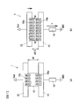
- FIG. 1 is a cross-sectional view showing a first embodiment of a vibration power generation element according to the present invention.
- FIG. 2 is a schematic diagram showing a main part of the vibration power generation element shown in FIG.
- FIG. 3 is a diagram for explaining a power generation operation in the first embodiment.
- FIG. 4 is a diagram illustrating a schematic configuration of the vibration power generation element according to the second embodiment.
- FIG. 5 is a schematic view showing a main part of the vibration power generation element shown in FIG.
- FIG. 6 is a diagram for explaining the power generation operation in the second embodiment.
- FIG. 7 is a diagram for explaining the third embodiment.
- FIG. 8 is a diagram illustrating a schematic configuration of the vibration power generation element according to the fourth embodiment.
- FIG. 8 is a diagram illustrating a schematic configuration of the vibration power generation element according to the fourth embodiment.
- FIG. 9 is a diagram for explaining the power generation operation in the fourth embodiment.
- FIG. 10 is a diagram showing a configuration when the electrode side vibrates in the second embodiment.
- FIG. 11 is a diagram illustrating a modification of the fourth embodiment.
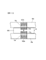
- FIG. 12 is a cross-sectional view of the vibration power generation element 1 according to the fifth embodiment.
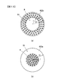
- FIG. 13 is a diagram illustrating the front and back surfaces of the movable substrate 42.
- FIG. 14 is a diagram for explaining the power generation operation in the fifth embodiment.
- FIG. 1 is a diagram for explaining a first embodiment of a vibration power generation element according to the present invention.
- 1A is a cross-sectional view of the vibration power generation element 1
- FIG. 1B is a cross-sectional view taken along the line AA of FIG. 1A.
- the vibration power generation element 1 includes a fixed electrode 11, a movable substrate 12, and an ionic liquid 13 (ionic liquid).
- the ionic liquid 13 is provided so as to be interposed between the fixed electrode 11 and the movable substrate 12.
- the fixed electrode 11 also serves as a bottom plate of the container provided in the vibration power generation element 1, and the fixed electrode 11 and the cylindrical portion 2 and the top plate 3 formed of an insulating material constitute a container.
- the movable substrate 12 and the ionic liquid 13 described above are stored in a container.
- the movable substrate 12 is provided so as to be movable in the vertical direction in FIG. 1A, and a movable range L in the vertical direction is defined by the ring-shaped stoppers 4a and 4b. Since the gas in the container hinders the movement of the movable substrate 12, the inside of the container is preferably kept in a vacuum state.
- the disc-shaped movable substrate 12 includes a support substrate 121 and an electret 122 provided on the lower surface of the support substrate 121 (a surface facing the fixed electrode 11).
- the electret 122 is obtained by electrifying a dielectric film such as polypropylene (PP) or polytetrafluoroethylene (PTFE) with a positive charge (or a negative charge) by corona discharge or the like. That is, the movable substrate 12 on which the electret 122 is formed functions as a movable electrode.
- a dielectric film such as polypropylene (PP) or polytetrafluoroethylene (PTFE) with a positive charge (or a negative charge) by corona discharge or the like. That is, the movable substrate 12 on which the electret 122 is formed functions as a movable electrode.
- the surface of the fixed electrode 11 that contacts the ionic liquid 13 is preferably excellent in water repellency.
- gold (Au) is preferably used as the electrode material.
- the ionic liquid 13 provided between the movable substrate 12 and the fixed electrode 11 is in contact with the electret 122 and the fixed electrode 11.
- the electret 122 is positively charged
- the negative ions of the ionic liquid 13 move in the electret direction
- the positive ions move in the fixed electrode 11 direction.
- the electric double layer 16b is formed across the interface between the electret 122 and the ionic liquid 13
- the electric double layer 16a is formed across the interface between the fixed electrode 11 and the ionic liquid 13.
- Various kinds of ionic liquid 13 can be used.
- 1-ethyl-3-methylimidazolium tetrafluoroborate is used as an example.
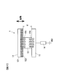
- FIG. 2 is a schematic diagram showing the main part of the vibration power generation element 1.
- the load 14 is connected to the fixed electrode 11.
- the potential of the movable substrate 12 is higher than the fixed electrode 11 by the electret voltage (the surface potential of the electret 122).
- the ionic liquid 13 is a kind of organic liquid composed only of positive ions and negative ions, and its vapor pressure is very low at room temperature and hardly evaporates. The viscosity is about 30 to 500 [Pa ⁇ s]. Since the ionic liquid 13 is composed only of ions and has good conductivity, it has a wide potential window and high electrical stability.
- the potential window is a potential region where no current substantially flows in the electrolytic solution.
- the ionic liquid 13 described above has a potential window of about ⁇ 1 to 3 [V].
- the voltage (surface potential) of the electret 122 described above is set within the range of the potential window of the ionic liquid 13.
- the voltage of the electret 122 is preferably set as large as possible within the range of the potential window.
- the voltage applied to the ionic liquid 13 by the electret 122 will be referred to as a bias voltage.
- Negative ions of the ionic liquid 13 provided between the electret 122 and the fixed electrode 11 are attracted toward the electret 122 by an electric field formed by the electret 122.
- the electric double layer 16b is formed across the interface between the electret 122 and the ionic liquid 13 as described above.
- positive ions of the ionic liquid 13 move to the fixed electrode 11 side and are electrically generated by the positive ions and the negative charges induced electrostatically on the fixed electrode 11 side.
- a double layer 16a is formed.
- the thickness of the electric double layer is about 1 [nm].
- the electrostatic capacity when an AC voltage is applied to the electric double layer is generally about 10 [ ⁇ F / cm 2 ] to 0.2 [ ⁇ F / cm 2 ] in the experimental range of 0.1 Hz to 1 MHz. It is known.
- the movable substrate 12 of the vibration power generation element 1 is configured to be movable in a direction in which the distance d between the fixed electrode 11 and the movable substrate 12 changes.
- the container of the vibration power generation element 1 vibrates (in particular, in the axial direction) due to external vibration (hereinafter referred to as “disturbance”)
- the movable substrate 12 vibrates in the illustrated vertical direction with respect to the fixed electrode 11.
- the movable substrate 12 can move up and down within a range d of d0 to d0 / 2. This movable range can be set by the positions of the stoppers 4a and 4b shown in FIG.
- the conventional vibration power generation element uses a change in electrostatic capacitance between electrodes (for example, between a metal electrode and an electret electrode), but the vibration power generation element 1 according to the present embodiment includes a movable substrate 12. It is characterized in that power generation is performed by changing the contact area of the ionic liquid 13 due to vibration (that is, changing the area of the electric double layer).
- the capacitance per unit area of the electric double layer varies depending on the bias voltage and the vibration frequency.
- the voltage of the electric double layers 16a and 16b is 1 [V]
- the amount of charge (charge amount) is 1 ⁇ 10 ⁇ 5 [C].
- the charge amount in the electrode is 10,000 compared with the vibration power generation element using the conventional electret. Double to 100,000 times very large. This is due to the use of an electric double layer having a layer thickness (in the following, represented by the symbol de) of the order of nm.
- the power generation is performed by changing the area of the electric double layer having such a large capacitance. Therefore, as will be described later, the power generation amount is significantly larger than that of the conventional vibration power generation element. be able to.
- the gap between the fixed electrode 11 and the movable substrate 12 includes a region where the ionic liquid 13 is interposed and a region of a simple space (in the case of the present embodiment, a vacuum). Even in the region where no intervenes, it has a capacitance.
- the capacitance in the region where the ionic liquid 13 is not present is zero, and the electric double layer capacitors are connected in series.
- power generation is substantially performed by the change in capacitance due to the change in the area of the electric double layers 16 a and 16 b.
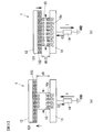
- FIG. 3 is a schematic diagram for explaining the operation of the vibration power generation element 1.
- the capacitance of the electric double layer 16a Increases from 5 [ ⁇ F] to 10 [ ⁇ F].
- the potential difference in the electric double layer 16a is assumed to be 1V
- a charge of 5 [ ⁇ C] passes through the load 14.
- the time required for the change from the state of FIG. 3A to the state of FIG. 3B is 0.05 [sec] (this corresponds to vibration of 20 Hz)
- the distance between the fixed electrode 11 and the electret 122 (hereinafter referred to as the electrode distance) changes as d0 ⁇ d1
- the contact area between the ionic liquid 13 and the fixed electrode 11, that is, the electric double layers 16a and 16b Consider a case where the area changes as S0 ⁇ S1.
- the electrostatic capacity of each electric double layer 16a, 16b is C
- the potential difference, area, and thickness in the electric double layers 16a, 16b are Ve, S, de
- C ⁇ ⁇ S / de holds.
- the vibration power generation element As described above, in the vibration power generation element according to the present embodiment, it is possible to obtain an extremely large amount of power generation by using the capacitance of the electric double layer by the ionic liquid.
- the capacitance of the electric double layer is very large compared to the capacitance of a general capacitor. Therefore, it is possible to obtain larger electric power with a small displacement and to reduce the size of the vibration power generation element.
- the area of the electric double layer is changed by changing the distance between the movable substrate 12 and the fixed electrode 11 due to disturbance, a large area change can be obtained with a small displacement, and the vibration power generation element 1 can be further downsized. Can be planned.
- a structure in which a movable part having a relatively large mass is movably supported by an elastic support part having a very small spring constant like the vibration power generation element described in Patent Document 1. It is. This is because vibration during walking, bridge vibration, or the like is used as vibration from the outside with respect to the vibration power generation element, and the vibration frequency is about several Hz to several tens Hz. In order to resonate at such a low frequency, a structure is used in which the movable part is supported by a very weak elastic support part. For this reason, the conventional vibration power generation element has a drawback that the elastic support portion is easily broken. In addition, since the resonance is used, there is a drawback that the usable band is narrow.
- this embodiment employs a sliding structure as shown in FIG. 1 so that the movable substrate 12 can freely vibrate.
- power generation can be performed efficiently regardless of the frequency of external vibration.
- the vibration power generation element of the present embodiment it is possible to adopt a structure in which the movable substrate 12 is supported by the elastic support portion.
- power generation is performed by changing the contact area with the ionic liquid 13, so that the contact surface with the ionic liquid 13, particularly the fixed electrode 11, can be changed effectively.
- the water repellency at the contact surface is important.
- gold used as the electrode material, it is excellent in water repellency, so water repellent treatment (for example, formation of a water repellent film) is not required, but water repellent treatment is required depending on the type of electrode material.
- the shape of the container is a cylinder and the fixed electrode 11 and the movable substrate 12 are disks.
- the present invention is not limited to these shapes.
- the fixed electrode 11 and the movable substrate 12 may be rectangular.
- the movable substrate 12 is configured to move up and down by the sliding structure, a configuration in which the electrode side vibrates may be used.
- the load 14 is directly connected to the fixed electrode 11.
- the power generation apparatus may be configured by providing a rectifier circuit, a power storage unit, or the like on the output side of the vibration power generation element 1. good.
- FIG. 4 is a diagram showing a schematic configuration of the vibration power generation element 1 and shows a cross-sectional shape similar to that in the case of FIG. In the following, the description will focus on the parts different from the configuration shown in FIG.
- electrets 222 a and 222 b are formed on the front and back surfaces of the support substrate 221.
- the first fixed electrode 11a is disposed so as to face the electret 222a
- the second fixed electrode 11b is disposed so as to face the electret 222b.
- the ionic liquid 13a is interposed in the gap between the electret 222a and the fixed electrode 11a
- the ionic liquid 13b is interposed in the gap between the electret 222b and the fixed electrode 11b.
- the movable substrate 22 is configured to be movable between the fixed electrodes 11a and 11b in the illustrated vertical direction, and the movable range 2L is set by the stoppers 4a and 4b.
- the case where the movable substrate 22 is in the center position of the movable range is shown.
- the cylindrical part 2, the fixed electrode 11 a attached to the lower opening of the cylindrical part 2, and the fixed electrode 11 b attached to the upper opening of the cylindrical part 2 constitute a container. As in the case of the first embodiment, the container is evacuated.
- FIG. 5 is a schematic diagram showing the main part of the vibration power generation element 1.
- FIG. 5 shows a load connection configuration in the case of taking out a current.
- the load 14 is connected between the fixed electrode 11a and the fixed electrode 11b, and the fixed electrode 11a is set at the GND potential.
- Each electret 222a, 222b is positively charged. Therefore, as in the case of the first embodiment, the electric double layer is formed at the interface between the ionic liquid 13a and the fixed electrode 11a and the electret 222a and at the interface between the ionic liquid 13b and the fixed electrode 11b and the electret 222b, respectively. Is formed.
- the electric double layer between the ionic liquid 13a and the fixed electrode 11a is represented by reference numeral 16a
- the electric double layer between the ionic liquid 13b and the fixed electrode 11b is represented by reference numeral 16b.
- the electric double layer formed at the interface between the ionic liquids 13a and 13b and the electrets 222a and 222b is denoted by reference numerals 16c and 16d.
- FIG. 6 is a diagram for explaining the current flowing through the load 14 when the movable substrate 22 vibrates.
- FIG. 6A shows a case where the movable substrate 22 has moved to the lower end of the movable range. At this time, the interval between the electret 222a and the fixed electrode 11a is set to d0 / 2, and the interval between the movable electrode 11b and the electret 222b is set to be d0.
- FIG. 6B shows a case where the movable substrate 22 has moved to the upper end of the movable range. The distance between the electret 222a and the fixed electrode 11a is d0, and the distance between the movable electrode 11b and the electret 222b is d0 / 2.
- the contact areas of the ionic liquid 13b with the fixed electrode 11b and the electret 222b are S0 and the ionic liquid 13a, respectively.
- the contact area between the fixed electrode 11a and the electret 222a is 2SO. Therefore, if the capacitance of the electric double layer 16b is C0, the capacitance of the electric double layer 16a is 2C0.
- the contact area between the ionic liquid 13b and the fixed electrode 11b and the electret 222b is 2S0
- the contact area between the ionic liquid 13a, the fixed electrode 11a and the electret 222a is S0.
- the potential difference between the movable substrate 22 and the fixed electrode 11a and the potential difference between the movable substrate 22 and the fixed electrode 11b are the same as the movable substrate 12 and the fixed electrode shown in FIG. 11 is the same as the relationship with.
- the potential difference between the fixed electrode 11a and the fixed electrode 11b is twice that of the configuration shown in FIG.
- the power (electric power) of power generation obtained in the case of the present embodiment is twice that in the case of the first embodiment shown in FIG.
- the generated power is output as a current, but it may be configured to take out the voltage.
- the operation is the same as that described in the first embodiment, and a description thereof is omitted here.
- the container has a cylindrical shape, and the fixed electrodes 11a and 11b and the movable substrate 22 have a disk shape.
- the present invention is not limited to these shapes.
- the movable substrate 22 is configured to move up and down by a sliding structure, for example, the movable substrate 22 may be configured to be supported by an elastic body.
- the electrode side may vibrate instead of the electret side.
- the movable electrode 10 is arranged to be movable in the vertical direction between a pair of electrets 222 a and 222 b that function as fixed electrodes.
- the electrets 222a and 222b are electretized so that the surface facing the movable electrode 10 is charged.
- the movable electrode 10 has a structure in which an insulating substrate 102 is sandwiched between electrodes 101a and 101b made of gold or the like.
- the electrode 101a faces the electret 222a
- the electrode 101b faces the electret 222b.
- the load 14 is connected between the electrode 101a and the electrode 101b.
- the contact area between the electrode 101a and the ionic liquid 13a increases, and the contact area between the electrode 101b and the ionic liquid 13b decreases.
- negative charges move from the electrode 101b to the electrode 101a via the load 14, and the current I flows through the load 14 in the upward direction in the figure.
- the movable electrode 10 moves in the direction of the electret 222b, negative charges move from the electrode 101a to the electrode 101b, and a current flows downward through the load 14 in the figure.
- FIG. 7 is a diagram for explaining a third embodiment of the present invention, and is a schematic diagram showing a main part of the vibration power generation element 1.
- the electret 122 is used to form the electric double layer 16a in the contact area between the ionic liquid 13 and the fixed electrode 11 as shown in FIG.
- the movable electrode 32 to which the bias voltage Vdd is applied by an external power source is used instead of the movable substrate 12 on which the electret 122 is formed.
- the electrode connected to the load may be moved up and down.
- an electric double layer is formed at the interface between the metal electrode and the ionic liquid by an electrokinetic phenomenon.
- an electrokinetic potential of about several tens [mV] is generated.
- the voltage is smaller than in the case of using the electret or the external power source described above, but an electric double layer corresponding to the voltage is generated at the interface between the metal electrode and the ionic liquid. Therefore, the vibration power generation element similar to that of the above-described embodiment can be configured by using the interface electrokinetic potential.
- -Fourth embodiment- 8 and 9 are diagrams showing a fourth embodiment of the present invention.
- the contact area between the ionic liquid and the substrate that is, the area of the electric double layer
- the area of the electric double layer is changed by sliding the movable substrate on which the electret is formed in parallel with the contact surface with the ionic liquid.
- FIG. 8 is a diagram showing a schematic configuration of the vibration power generation element 1.
- FIG. 8A is a cross-sectional view of the vibration power generation element 1
- FIG. 8B is a cross-sectional view along the line BB.
- the vibration power generation element 1 includes a pair of fixed electrodes 11a and 11b and a movable substrate 42 arranged between them.
- the fixed electrode 11a is fixed to the frame member 43a so as to be fitted into the hole 430 of the frame member 43a.
- the fixed electrode 11b is fixed to the frame member 43b so as to be fitted into the hole 431 of the frame member 43b.
- the hole 430 and the hole 431 are opposed to each other.
- Balls 432 are provided on the surfaces of the frame members 43a and 43b facing the movable substrate 42, respectively. As shown in FIG. 8B, a plurality of balls 432 are arranged on the circumference centering on the central axis of the holes 430 and 431.
- the movable substrate 42 is disposed so as to be sandwiched between a ball 432 provided on the frame member 43a and a ball 432 provided on the frame member 43b.
- the frame members 43a and 43b are formed of an insulating material.
- the ball 432 is also preferably formed of an insulating material (for example, a ceramic ball).
- the hole 430 in which the fixed electrode 11a is fitted is filled with the ionic liquid 13a, and the ionic liquid 13a is interposed between the fixed electrode 11a and the movable substrate 42.
- the hole 431 in which the fixed electrode 11b is fitted is filled with the ionic liquid 13b, and the ionic liquid 13b is interposed between the fixed electrode 11b and the movable substrate.
- the disk-shaped movable substrate 42 is obtained by providing dielectric members 422 a and 422 b on the front and back surfaces of the support substrate 421.
- the dielectric members 422a and 422b only the central circular region R is electretized by the charging process. That is, the dielectric members 422a and 422b in the circular region R function as electrets.
- the circular region R will be referred to as an electret R.
- the electret (circular region) R is set substantially the same as the cross-sectional shape of the holes 430 and 431.
- the movable substrate 42, the frame member 43a provided with the fixed electrode 11a, and the frame member 43b provided with the fixed electrode 11b are the cylindrical portion 440, the top plate 441 provided in the upper opening of the cylindrical portion 440, and the cylindrical portion 440. It is housed in a container composed of a bottom plate 442 provided in the lower opening.
- the lower end surface of the fixed electrode 11a is exposed to the outside through a hole formed in the central portion of the bottom plate 442.
- the upper end surface of the fixed electrode 11b is exposed to the outside through a hole formed in the center of the top plate 441.
- the frame member 43 a is fixed to the cylindrical portion 440 or the bottom plate 442.
- the frame member 43b is fixed to the cylindrical portion 440 or the top plate 441. Therefore, when external vibration is applied to the container, the movable substrate 42 slides in the left-right direction with respect to the frame members 43a and 43b.
- the inside of the container is preferably evacuated so as not to disturb the vibration of the movable substrate 42
- FIG. 9 is a diagram for explaining the power generation operation in the fourth embodiment.
- the movable substrate 42 has the dielectric members 422 a and 422 b formed on the front and back surfaces of the support substrate 421.
- the central region of the dielectric members 422a and 422b is an electret R that is positively charged.
- the electret R faces the portions of the ionic liquids 13a and 13b.
- electric double layers 16a and 16b are formed across the interface between electret R and ionic liquids 13a and 13b.
- an electric double layer 16c is formed across the interface between the fixed electrode 11a and the ionic liquid 13a
- an electric double layer 16d is formed across the interface between the fixed electrode 11b and the ionic liquid 13b.
- the fixed electrodes 11a and 11b are arranged on both the upper and lower sides of the movable substrate 42 that slides.
- the fixed electrode may be provided only on one side of the movable substrate 42.
- a current twice as large as that in the configuration in which the fixed electrodes are arranged only on one side can be obtained.
- electrets 522a and 522b are arranged at the positions of the fixed electrodes 11a and 11b, respectively, and the electrodes 11a and 11b are arranged in the circular region R (which is a recess) of the movable substrate 52.
- an electrode to which a bias voltage is applied may be disposed instead of the electrets 522a and 522b.
- electrodes 11 a and 11 b are provided on the front and back surfaces of an insulating support substrate 520.
- the fixed electrodes 11a and 11b and the electret R do not have to be circular.
- the rectangular electret slides in a direction perpendicular to the rectangular side with respect to the rectangular fixed electrode. Also good.
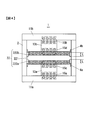
- FIG. 12 is a cross-sectional view of the vibration power generation element 1
- FIG. 13 is a diagram illustrating the front and back surfaces of the movable substrate 42.
- the fifth embodiment is different from the fourth embodiment in the form of electret regions of the dielectric members 422a and 422b provided on the front and back surfaces of the movable substrate.
- Other configurations are the same as those in the fourth embodiment, and a description thereof will be omitted.
- both the dielectric members 422a and 422b electrify the central region R.
- the central region R region of radius r
- the central region R for the dielectric member 422b is electretized for the dielectric member 422a, but the central region R for the dielectric member 422b.
- a region R1 outside R region of radius r to 2r is electretized.
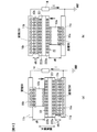
- FIG. 14 is a diagram for explaining the power generation operation.
- the central region R of the movable substrate 42 faces the fixed electrodes 11a and 11b (that is, the ionic liquids 13a and 13b).
- the electric double layer 16a is formed in the contact region between the electret region of the dielectric member 422a and the ionic liquid 13a
- the electric double layer 16c is formed in the contact region between the fixed electrode 11a and the ionic liquid 13a. Is done.
- the area of the electric double layers 16a and 16c in this case is the same as the area of the region R.
- the area of the portion of the dielectric member 422a that is electretized that faces the fixed electrode 11a decreases.
- the areas of the electric double layers 16a and 16c are also reduced.
- the dielectric member 422a a part of the electret region R1 is opposed to the fixed electrode 11b.
- the electric double layer 16b is formed in the contact region between the electretized region R1 of the dielectric member 422b and the ionic liquid 13b, and the contact region between the fixed electrode 11b and the ionic liquid 13b is correspondingly formed.
- the electric double layer 16d is formed. That is, the area of the electric double layer increases on the ionic liquid 13b side. As a result, a current flows through the load 14 in the direction of the arrow.
- the fixed electrode 11 is disposed to face the fixed electrode 11 and the distance between the fixed electrode 11 is changed (
- the movable substrate 12 is movable in the vertical direction in the figure, and the ionic liquid 13 is provided so as to be interposed between the fixed electrode 11 and the movable substrate 12 that are arranged to face each other.
- the thickness of the electric double layer is on the order of nm, which is an order of magnitude smaller than the distance between the electrodes of a conventional vibration power generation element, so that the capacitance change accompanying the vibration of the movable substrate 12 is also an order of magnitude.
- nm is an order of magnitude smaller than the distance between the electrodes of a conventional vibration power generation element, so that the capacitance change accompanying the vibration of the movable substrate 12 is also an order of magnitude.
- the electric double layers 16a and 16b can be stably formed without current flowing through the ionic liquid 13.
- the electret 122 may be used as described above, or an electric double layer generated by an electrokinetic phenomenon may be used, as shown in FIG.
- the electric double layer may be formed by providing a voltage source and applying a bias voltage to the movable electrode.
- the bias voltage is set within the range of the potential window described above.
- the movable substrate 22 has an electret 222b as a front surface side electrode and an electret 222a as a back surface side electrode on the front and back surfaces thereof, and the fixed electrode 11b disposed to face the electret 222b. And the fixed electrode 11a disposed opposite to the electret 222a.
- the ionic liquid 13b is interposed between the fixed electrode 11b and the electret 222b, and the ionic liquid 13a is interposed between the fixed electrode 11a and the electret 222a.
- the voltage change between the fixed electrode 11a and the fixed electrode 11b is twice as compared with the case where there is one fixed electrode 11 as shown in FIG.
- ionic liquids 13a and 13b are interposed between the fixed electrodes 11a and 11b and the movable substrate 42, and the movable substrate 42 is slid with respect to the fixed electrodes 11a and 11b. May be.
- the contact area between the electret regions R of the dielectric members 422a and 422b provided on the front and back surfaces of the movable substrate 42 and the ionic liquids 13a and 13b changes, and the fixed electrodes 11a and 11b.
- the present invention is not limited to the above embodiment as long as the characteristics of the present invention are not impaired.
- capacitance by the electric double layer using the ionic liquid shown here can be utilized as an electrical storage element with a big capacity
- this power storage element can be used for the purpose of accumulating electric charges generated by external vibration until it is necessary to use electric power. Since the power storage element can also be composed of a material and a structure similar to those of the power generation element, a device having both functions of power generation and power storage can be easily manufactured.
Landscapes
- Engineering & Computer Science (AREA)
- Chemical & Material Sciences (AREA)
- Combustion & Propulsion (AREA)
- Power Engineering (AREA)
- Mechanical Engineering (AREA)
- General Engineering & Computer Science (AREA)
- Micromachines (AREA)
- Electrostatic, Electromagnetic, Magneto- Strictive, And Variable-Resistance Transducers (AREA)
- General Electrical Machinery Utilizing Piezoelectricity, Electrostriction Or Magnetostriction (AREA)
- Electrostatic Separation (AREA)
Abstract
Description
本発明の第2の態様によると、第1の態様の振動発電素子において、可動電極は、固定電極との間隔が変化する方向に移動可能であり、外部からの振動による可動電極の移動により、固定電極とイオン液体との界面を挟んで形成される電気二重層、および可動電極とイオン液体との界面を挟んで形成される電気二重層の面積がそれぞれ変化することが好ましい。
本発明の第3の態様によると、第2の態様の振動発電素子において、互いに対向する固定電極および可動電極の一方はエレクトレット電極であり、エレクトレット電極の表面電位はイオン液体の電位窓の範囲内に設定されていることが好ましい。
本発明の第4の態様によると、第2の態様の振動発電素子において、電気二重層は、固定電極および可動電極とイオン液体との接触領域に生じる界面動電現象により形成されたものであることが好ましい。
本発明の第5の態様によると、第2乃至4のいずれか一態様の振動発電素子において、可動電極は、該可動電極の表面側に設けられた表面側電極と、可動電極の裏面側に設けられた裏面側電極とを有し、固定電極は、表面側電極に対して対向配置された第1電極と裏面側電極に対して対向配置された第2電極とを有し、イオン液体は、第1電極と表面側電極との間、および、第2電極と裏面側電極との間にそれぞれ介在するように設けられていることが好ましい。
本発明の第6の態様によると、第1の態様の振動発電素子において、可動電極は、固定電極との間隔を一定に保持した状態でスライド移動可能であり、外部からの振動による可動電極のスライド移動により、可動電極とイオン液体との界面を挟んで形成される電気二重層の面積が変化することが好ましい。
本発明の第7の態様によると、第6の態様の振動発電素子において、可動電極は、可動基板と、可動基板の固定電極と対向する面に設けられ、表面電位がイオン液体の電位窓の範囲内に設定されているエレクトレット電極とを有し、可動電極のスライド移動により、エレクトレット電極とイオン液体との界面を挟んで形成される電気二重層の面積が変化することが好ましい。
本発明の第8の態様によると、第7の態様の振動発電素子において、可動電極は、可動基板の表面に設けられた第1エレクトレット電極と、可動基板の裏面に設けられた第2エレクトレット電極とを有し、固定電極は、可動基板の表面に対して対向配置された第1電極と可動基板の裏面に対して対向配置された第2電極とを有し、イオン液体は、第1電極と可動基板の表面との間、および、第2電極と可動基板の裏面との間にそれぞれ介在するように設けられていることが好ましい。
図1は、本発明による振動発電素子の第1の実施の形態を説明する図である。図1(a)は振動発電素子1の断面図であり、図1(b)は図1(a)のA-A断面図である。振動発電素子1は、固定電極11と可動基板12とイオン液体13(ionic liquid)とを備えている。イオン液体13は、固定電極11と可動基板12との間に介在するように設けられている。固定電極11は振動発電素子1に設けられた容器の底板を兼ねており、この固定電極11と絶縁材料で形成された円筒部2および天板3とで容器が構成されている。
図4~6は、本発明の第2の実施の形態を説明する図である。図4は振動発電素子1の概略構成を示す図であり、図1(a)の場合と同様の断面形状を示したものである。なお、以下では図1に示す構成と異なる部分を中心に説明する。
図7は本発明の第3の実施の形態を説明する図であり、振動発電素子1の要部を示す模式図である。上述した第1の実施の形態では、図2に示したようにイオン液体13と固定電極11との接触領域に電気二重層16aを形成するために、エレクトレット122を用いた。本実施の形態では、エレクトレット122が形成された可動基板12に代えて、外部電源によりバイアス電圧Vddが印加された可動電極32を用いる構成とした。
図8,9は、本発明の第4の実施形態を示す図である。上述した第1~第3の実施の形態では、隙間にイオン液体13を保持した一対の基板の間隔を変化させることによって、イオン液体と基板との接触面積(すなわち、電気二重層の面積)を変化させ、発電を行うようにした。本実施の形態では、エレクトレットが形成された可動基板を、イオン液体との接触面に対して平行にスライド移動させることにより、電気二重層の面積を変化させるようにした。
図12~14は、本発明の第5の実施の形態を示す図である。図12は振動発電素子1の断面図であり、図13は、可動基板42の表裏面を示す図である。第5の実施の形態は、可動基板42の表裏面に設けられた誘電体部材422a,422bのエレクトレット化領域の形態が第4の実施の形態と異なる。その他の構成については第4の実施の形態と同様であり、説明を省略する。
日本国特許出願2014年第36507号(2014年2月27日出願)
Claims (8)
- 固定電極と、
前記固定電極に対して対向配置され、前記固定電極に対して移動可能な可動電極と、
対向配置された前記固定電極と前記可動電極との間に介在するように設けられたイオン液体と、を備え、
外部からの振動による前記可動電極の移動により、前記固定電極と前記イオン液体との界面を挟んで形成される電気二重層、および前記可動電極と前記イオン液体との界面を挟んで形成される電気二重層の、少なくとも一方の面積が変化することによって発電を行う、振動発電素子。 - 請求項1に記載の振動発電素子において、
前記可動電極は、前記固定電極との間隔が変化する方向に移動可能であり、
外部からの振動による前記可動電極の移動により、前記固定電極と前記イオン液体との界面を挟んで形成される電気二重層、および前記可動電極と前記イオン液体との界面を挟んで形成される電気二重層の面積がそれぞれ変化する、振動発電素子。 - 請求項2に記載の振動発電素子において、
互いに対向する前記固定電極および前記可動電極の一方はエレクトレット電極であり、
前記エレクトレット電極の表面電位は前記イオン液体の電位窓の範囲内に設定されている振動発電素子。 - 請求項2に記載の振動発電素子において、
前記電気二重層は、前記固定電極および前記可動電極と前記イオン液体との接触領域に生じる界面動電現象により形成されたものである振動発電素子。 - 請求項2乃至4のいずれか一項に記載の振動発電素子において、
前記可動電極は、該可動電極の表面側に設けられた表面側電極と、前記可動電極の裏面側に設けられた裏面側電極とを有し、
前記固定電極は、前記表面側電極に対して対向配置された第1電極と前記裏面側電極に対して対向配置された第2電極とを有し、
前記イオン液体は、前記第1電極と前記表面側電極との間、および、前記第2電極と前記裏面側電極との間にそれぞれ介在するように設けられている振動発電素子。 - 請求項1に記載の振動発電素子において、
前記可動電極は、前記固定電極との間隔を一定に保持した状態でスライド移動可能であり、
外部からの振動による前記可動電極のスライド移動により、前記可動電極と前記イオン液体との界面を挟んで形成される電気二重層の面積が変化する、振動発電素子。 - 請求項6に記載の振動発電素子において、
前記可動電極は、
可動基板と、
前記可動基板の前記固定電極と対向する面に設けられ、表面電位が前記イオン液体の電位窓の範囲内に設定されているエレクトレット電極とを有し、
前記可動電極のスライド移動により、前記エレクトレット電極と前記イオン液体との界面を挟んで形成される電気二重層の面積が変化する振動発電素子。 - 請求項7に記載の振動発電素子において、
前記可動電極は、前記可動基板の表面に設けられた第1エレクトレット電極と、前記可動基板の裏面に設けられた第2エレクトレット電極とを有し、
前記固定電極は、前記可動基板の表面に対して対向配置された第1電極と前記可動基板の裏面に対して対向配置された第2電極とを有し、
前記イオン液体は、前記第1電極と前記可動基板の表面との間、および、前記第2電極と前記可動基板の裏面との間にそれぞれ介在するように設けられている振動発電素子。
Priority Applications (3)
| Application Number | Priority Date | Filing Date | Title |
|---|---|---|---|
| JP2016505132A JP6230137B2 (ja) | 2014-02-27 | 2015-02-09 | 振動発電素子 |
| CN201580008349.2A CN106031014B (zh) | 2014-02-27 | 2015-02-09 | 振动发电元件 |
| US15/121,128 US10566912B2 (en) | 2014-02-27 | 2015-02-09 | Vibration-driven energy harvester |
Applications Claiming Priority (2)
| Application Number | Priority Date | Filing Date | Title |
|---|---|---|---|
| JP2014-036507 | 2014-02-27 | ||
| JP2014036507 | 2014-02-27 |
Publications (1)
| Publication Number | Publication Date |
|---|---|
| WO2015129442A1 true WO2015129442A1 (ja) | 2015-09-03 |
Family
ID=54008766
Family Applications (1)
| Application Number | Title | Priority Date | Filing Date |
|---|---|---|---|
| PCT/JP2015/053523 Ceased WO2015129442A1 (ja) | 2014-02-27 | 2015-02-09 | 振動発電素子 |
Country Status (4)
| Country | Link |
|---|---|
| US (1) | US10566912B2 (ja) |
| JP (2) | JP6230137B2 (ja) |
| CN (1) | CN106031014B (ja) |
| WO (1) | WO2015129442A1 (ja) |
Cited By (5)
| Publication number | Priority date | Publication date | Assignee | Title |
|---|---|---|---|---|
| WO2016114361A1 (ja) * | 2015-01-16 | 2016-07-21 | 国立大学法人 東京大学 | 振動発電素子 |
| JP2018088780A (ja) * | 2016-11-29 | 2018-06-07 | 国立大学法人 東京大学 | 振動発電素子 |
| JPWO2017090727A1 (ja) * | 2015-11-25 | 2018-09-13 | 国立大学法人 東京大学 | 静電誘導型発電素子 |
| JP2021069280A (ja) * | 2021-02-04 | 2021-04-30 | 国立大学法人 東京大学 | 振動発電素子 |
| JP2022082718A (ja) * | 2021-02-04 | 2022-06-02 | 国立大学法人 東京大学 | 振動発電素子 |
Families Citing this family (27)
| Publication number | Priority date | Publication date | Assignee | Title |
|---|---|---|---|---|
| US11554576B2 (en) | 2017-01-26 | 2023-01-17 | Face International Corporation | Energy harvesting methods for providing autonomous electrical power to mobile devices |
| US9726791B2 (en) | 2015-04-14 | 2017-08-08 | Face International Corporation | Systems and methods for producing objects incorporating selectably active electromagnetic energy filtering layers and coatings |
| US11966066B2 (en) | 2017-01-25 | 2024-04-23 | Face International Corporation | Delivery systems and methods for compositions of materials for forming coatings and layered structures including elements for scattering and passing selectively tunable wavelengths of electromagnetic energy |
| US12181693B2 (en) | 2015-04-14 | 2024-12-31 | Face International Corporation | Image capturing system with wavelength-selective energy scattering layer |
| DE202015104016U1 (de) * | 2015-07-31 | 2016-11-03 | R2Di2 Ag | Brücke |
| US12201021B2 (en) | 2016-04-09 | 2025-01-14 | Face International Corporation | Methods for fabrication, manufacture and production of energy harvesting components and devices |
| US11980102B2 (en) | 2016-04-09 | 2024-05-07 | Face International Corporation | Systems and devices powered by autonomous electrical power sources |
| US11957922B2 (en) | 2016-04-09 | 2024-04-16 | Face International Corporation | Structurally embedded and inhospitable environment systems having autonomous electrical power sources |
| US9793317B1 (en) | 2016-04-09 | 2017-10-17 | Face International Corporation | Devices and systems incorporating energy harvesting components/devices as autonomous energy sources and as energy supplementation, and methods for producing devices and systems incorporating energy harvesting components/devices |
| US9786718B1 (en) | 2016-04-09 | 2017-10-10 | Face International Corporation | Integrated circuit components incorporating energy harvesting components/devices, and methods for fabrication, manufacture and production of integrated circuit components incorporating energy harvesting components/devices |
| US10985677B2 (en) | 2017-04-10 | 2021-04-20 | Face International Corporation | Systems and devices powered by autonomous electrical power sources |
| US10056538B1 (en) | 2016-04-09 | 2018-08-21 | Face International Corporation | Methods for fabrication, manufacture and production of energy harvesting components and devices |
| US10109781B1 (en) | 2017-04-10 | 2018-10-23 | Face International Corporation | Methods for fabrication, manufacture and production of an autonomous electrical power source |
| US10079561B1 (en) | 2016-04-09 | 2018-09-18 | Face International Corporation | Energy harvesting components and devices |
| US9893261B1 (en) | 2017-04-10 | 2018-02-13 | Face International Corporation | Structurally embedded and inhospitable environment systems and devices having autonomous electrical power sources |
| WO2018237156A1 (en) * | 2017-06-21 | 2018-12-27 | Inspire Medical Systems, Inc. | Self-power sensor |
| JP2019033631A (ja) * | 2017-08-09 | 2019-02-28 | 国立大学法人静岡大学 | Mems振動素子、mems振動素子の製造方法および振動発電素子 |
| JP7037144B2 (ja) * | 2017-08-09 | 2022-03-16 | 国立大学法人静岡大学 | Mems振動素子の製造方法およびmems振動素子 |
| JP2019057540A (ja) * | 2017-09-19 | 2019-04-11 | 東芝メモリ株式会社 | 記憶素子 |
| JP6985702B2 (ja) * | 2018-05-31 | 2021-12-22 | 国立大学法人 東京大学 | 振動発電装置および振動発電素子 |
| US11228197B2 (en) * | 2019-04-17 | 2022-01-18 | The Hong Kong University Of Science And Technology | Energy conversion system and method by phase transforming materials |
| CN110086377B (zh) * | 2019-05-29 | 2020-05-29 | 厦门大学 | 基于溶液中双电荷层的单电极发电机及其发电方法 |
| CN110190772B (zh) * | 2019-05-29 | 2020-05-29 | 厦门大学 | 基于液体中双电荷层的独立感应式发电机及其发电方法 |
| JP7282365B2 (ja) * | 2019-06-12 | 2023-05-29 | 国立大学法人 東京大学 | 静電誘導型発電素子に使用される電極基板 |
| JP7311330B2 (ja) * | 2019-07-04 | 2023-07-19 | 東邦化成株式会社 | 環境発電用耐熱エレクトレット素子及びそれを用いた振動発電素子 |
| KR102239695B1 (ko) * | 2019-10-10 | 2021-04-13 | 울산대학교 산학협력단 | 인체내장형 유체마찰 발전기 |
| CN111987934B (zh) * | 2020-08-14 | 2024-04-02 | 河海大学 | 一种悬臂梁振动发电装置 |
Citations (2)
| Publication number | Priority date | Publication date | Assignee | Title |
|---|---|---|---|---|
| US7898096B1 (en) * | 2007-08-22 | 2011-03-01 | Thomas Nikita Krupenkin | Method and apparatus for energy harvesting using microfluidics |
| JP2011507479A (ja) * | 2007-12-21 | 2011-03-03 | コミッサリア ア レネルジー アトミーク エ オ ゼネルジ ザルタナテイヴ | 液状電極を有するエネルギー回復装置 |
Family Cites Families (7)
| Publication number | Priority date | Publication date | Assignee | Title |
|---|---|---|---|---|
| US7446450B2 (en) * | 2004-06-07 | 2008-11-04 | California Institute Of Technology | Method and system using liquid dielectric for electrostatic power generation |
| JP4882639B2 (ja) | 2006-09-29 | 2012-02-22 | ブラザー工業株式会社 | アクチュエータ、ポンプ、及び、光スキャナ |
| JP2011036089A (ja) | 2009-08-05 | 2011-02-17 | Panasonic Corp | 振動発電素子およびその製造方法 |
| CN103181016B (zh) * | 2010-09-13 | 2016-06-22 | 加利福尼亚大学董事会 | 离子凝胶电解质、储能设备及其制造方法 |
| US20140055002A1 (en) * | 2011-10-19 | 2014-02-27 | Panasonic Corporation | Vibration power generator, rotating body and communication device |
| US20140070664A1 (en) * | 2012-03-26 | 2014-03-13 | Panasonic Corporation | Vibration power generator |
| KR101358291B1 (ko) * | 2012-10-31 | 2014-02-12 | 서울대학교산학협력단 | 액체의 접촉각 및 접촉면적의 변화를 이용한 에너지 전환 장치 |
-
2015
- 2015-02-09 JP JP2016505132A patent/JP6230137B2/ja active Active
- 2015-02-09 CN CN201580008349.2A patent/CN106031014B/zh active Active
- 2015-02-09 WO PCT/JP2015/053523 patent/WO2015129442A1/ja not_active Ceased
- 2015-02-09 US US15/121,128 patent/US10566912B2/en active Active
-
2017
- 2017-10-12 JP JP2017198744A patent/JP6425181B2/ja active Active
Patent Citations (2)
| Publication number | Priority date | Publication date | Assignee | Title |
|---|---|---|---|---|
| US7898096B1 (en) * | 2007-08-22 | 2011-03-01 | Thomas Nikita Krupenkin | Method and apparatus for energy harvesting using microfluidics |
| JP2011507479A (ja) * | 2007-12-21 | 2011-03-03 | コミッサリア ア レネルジー アトミーク エ オ ゼネルジ ザルタナテイヴ | 液状電極を有するエネルギー回復装置 |
Cited By (7)
| Publication number | Priority date | Publication date | Assignee | Title |
|---|---|---|---|---|
| WO2016114361A1 (ja) * | 2015-01-16 | 2016-07-21 | 国立大学法人 東京大学 | 振動発電素子 |
| JPWO2016114361A1 (ja) * | 2015-01-16 | 2017-10-12 | 国立大学法人 東京大学 | 振動発電素子 |
| US10309379B2 (en) | 2015-01-16 | 2019-06-04 | The University Of Tokyo | Vibration energy harvester |
| JPWO2017090727A1 (ja) * | 2015-11-25 | 2018-09-13 | 国立大学法人 東京大学 | 静電誘導型発電素子 |
| JP2018088780A (ja) * | 2016-11-29 | 2018-06-07 | 国立大学法人 東京大学 | 振動発電素子 |
| JP2021069280A (ja) * | 2021-02-04 | 2021-04-30 | 国立大学法人 東京大学 | 振動発電素子 |
| JP2022082718A (ja) * | 2021-02-04 | 2022-06-02 | 国立大学法人 東京大学 | 振動発電素子 |
Also Published As
| Publication number | Publication date |
|---|---|
| CN106031014B (zh) | 2019-05-17 |
| JP6425181B2 (ja) | 2018-11-21 |
| JP6230137B2 (ja) | 2017-11-15 |
| US10566912B2 (en) | 2020-02-18 |
| JPWO2015129442A1 (ja) | 2017-03-30 |
| CN106031014A (zh) | 2016-10-12 |
| US20170019034A1 (en) | 2017-01-19 |
| JP2018050455A (ja) | 2018-03-29 |
Similar Documents
| Publication | Publication Date | Title |
|---|---|---|
| JP6230137B2 (ja) | 振動発電素子 | |
| JP6241970B2 (ja) | 振動発電素子 | |
| Suzuki | Recent progress in MEMS electret generator for energy harvesting | |
| Li et al. | Recent progress on mechanical optimization of MEMS electret-based electrostatic vibration energy harvesters | |
| Tao et al. | Enhanced electrostatic vibrational energy harvesting using integrated opposite-charged electrets | |
| US6966225B1 (en) | Capacitive accelerometer with liquid dielectric | |
| Liu et al. | Investigation of a MEMS piezoelectric energy harvester system with a frequency-widened-bandwidth mechanism introduced by mechanical stoppers | |
| Yang et al. | Power generation from conductive droplet sliding on electret film | |
| US7872851B2 (en) | Fluidic based variable capacitor for use in a fluidic electrostatic energy harvester | |
| Zhang et al. | Micro energy harvester with dual electrets on sandwich structure optimized by air damping control for wireless sensor network application | |
| US20130241346A1 (en) | Device for converting mechanical energy into electrical energy | |
| WO2018091690A1 (en) | Mems microphone system having an electrode assembly | |
| KR102060065B1 (ko) | 에너지 수확 장치 | |
| Adhikari et al. | High power density and bias-free reverse electrowetting energy harvesting using surface area enhanced porous electrodes | |
| Xu et al. | Double layered dielectric elastomer by vapor encapsulation casting for highly deformable and strongly adhesive triboelectric materials | |
| Bu et al. | Liquid encapsulated electrostatic energy harvester for low-frequency vibrations | |
| Fu et al. | MEMS vibration electret energy harvester with combined electrodes | |
| JP5273643B2 (ja) | 物質の位置及び形状制御装置並びに物質の位置及び形状制御方法 | |
| Takahashi et al. | A miniature harvester of vertical vibratory capacitive type achieving several tens microwatt for broad frequency of 20–40 Hz | |
| Kim et al. | Electrostatic energy harvester using magnetically actuated liquid dielectric layers | |
| JP2014087179A (ja) | 振動発電器 | |
| Héctor | Understanding Nanoelectromechanical Quantum Circuits and Systems (NEMX) for the Internet of Things (IoT) Era | |
| Tao et al. | A sandwich-structured MEMS electret power generator for multi-directional vibration energy harvesting | |
| JP2015004546A (ja) | 静電容量変化検出モジュール及びmemsセンサ | |
| JP2008267809A (ja) | 容量検出回路 |
Legal Events
| Date | Code | Title | Description |
|---|---|---|---|
| 121 | Ep: the epo has been informed by wipo that ep was designated in this application |
Ref document number: 15755253 Country of ref document: EP Kind code of ref document: A1 |
|
| ENP | Entry into the national phase |
Ref document number: 2016505132 Country of ref document: JP Kind code of ref document: A |
|
| WWE | Wipo information: entry into national phase |
Ref document number: 15121128 Country of ref document: US |
|
| NENP | Non-entry into the national phase |
Ref country code: DE |
|
| 122 | Ep: pct application non-entry in european phase |
Ref document number: 15755253 Country of ref document: EP Kind code of ref document: A1 |