WO2015129214A1 - 経路探索装置、経路探索方法およびプログラム - Google Patents
経路探索装置、経路探索方法およびプログラム Download PDFInfo
- Publication number
- WO2015129214A1 WO2015129214A1 PCT/JP2015/000798 JP2015000798W WO2015129214A1 WO 2015129214 A1 WO2015129214 A1 WO 2015129214A1 JP 2015000798 W JP2015000798 W JP 2015000798W WO 2015129214 A1 WO2015129214 A1 WO 2015129214A1
- Authority
- WO
- WIPO (PCT)
- Prior art keywords
- route
- candidate
- value
- route search
- link
- Prior art date
Links
Images


Classifications
-
- G—PHYSICS
- G01—MEASURING; TESTING
- G01C—MEASURING DISTANCES, LEVELS OR BEARINGS; SURVEYING; NAVIGATION; GYROSCOPIC INSTRUMENTS; PHOTOGRAMMETRY OR VIDEOGRAMMETRY
- G01C21/00—Navigation; Navigational instruments not provided for in groups G01C1/00 - G01C19/00
- G01C21/26—Navigation; Navigational instruments not provided for in groups G01C1/00 - G01C19/00 specially adapted for navigation in a road network
- G01C21/34—Route searching; Route guidance
- G01C21/3453—Special cost functions, i.e. other than distance or default speed limit of road segments
-
- G—PHYSICS
- G08—SIGNALLING
- G08G—TRAFFIC CONTROL SYSTEMS
- G08G1/00—Traffic control systems for road vehicles
- G08G1/09—Arrangements for giving variable traffic instructions
- G08G1/0962—Arrangements for giving variable traffic instructions having an indicator mounted inside the vehicle, e.g. giving voice messages
- G08G1/0968—Systems involving transmission of navigation instructions to the vehicle
- G08G1/096805—Systems involving transmission of navigation instructions to the vehicle where the transmitted instructions are used to compute a route
- G08G1/096827—Systems involving transmission of navigation instructions to the vehicle where the transmitted instructions are used to compute a route where the route is computed onboard
-
- G—PHYSICS
- G08—SIGNALLING
- G08G—TRAFFIC CONTROL SYSTEMS
- G08G1/00—Traffic control systems for road vehicles
- G08G1/09—Arrangements for giving variable traffic instructions
- G08G1/0962—Arrangements for giving variable traffic instructions having an indicator mounted inside the vehicle, e.g. giving voice messages
- G08G1/0968—Systems involving transmission of navigation instructions to the vehicle
- G08G1/096833—Systems involving transmission of navigation instructions to the vehicle where different aspects are considered when computing the route
- G08G1/096838—Systems involving transmission of navigation instructions to the vehicle where different aspects are considered when computing the route where the user preferences are taken into account or the user selects one route out of a plurality
Definitions
- the present invention relates to a technique for searching for a route from a departure place to a destination.
- a route search device for searching for a route from a departure place to a destination in recent years, as in JP 2012-141145 A and JP 2008-241605 A, a car navigation system and a mobile phone mounted on an automobile.
- a portable game machine, a PND (Personal Navigation Device), and a PDA (Personal Digital Assistant) are known.
- a variation value indicating variation in the reference passage time and passage time set for each link is used. Yes. Specifically, the estimated time is reached by calculating the required time of the guide route, which is the sum of the reference transit times of the links that make up the guide route in the order of the links, and adding the variation values of the links in the order of the links. Probability is calculated.
- the variation value set for each link is a constant value. Therefore, the contents of the route search may lack flexibility. For example, depending on the user, there may be a case where a route search considering only the reference transit time is desired, or a route search considering a variation value. There is also a desire to change the degree of variation value when calculating a route search result even when performing a route search in consideration of the variation value. Further, in the prior art, improvement in processing efficiency, downsizing of the apparatus, cost reduction, resource saving, improvement in usability, and the like have been desired.
- the present invention has been made to solve the above-described problems, and can be realized as the following forms or application examples.
- a route search device that searches for a route from a set departure point to a destination.
- the route search device stores network data including nodes and links representing a road network, an average cost value representing an average of transit times of the links, and a variation value representing a degree of variation in the transit time.
- a route from the starting point to the destination is recommended based on a total cost value calculated according to a function including the average cost value, the variation value, and a weighting factor of the variation value.
- a route search unit that determines the route.
- the recommended route can be determined in consideration of the weighting coefficient of the variation value, so that a highly flexible route search can be performed.
- the route search unit includes the average cost corresponding to the link that has passed from the departure place to the destination among a plurality of route candidates that are candidates for the recommended route.
- the total cost value is obtained by adding a correction value calculated by multiplying the integrated value of the value by a value having a positive correlation with the integrated value of the variation value corresponding to the weighted coefficient and the passed link. It may be calculated. According to the route search device of this aspect, the total cost value can be easily calculated using a predetermined function.
- the route search unit passes the route from the departure point to the node in the middle of the route in the route from the departure point to the destination.
- a second term indicating a correction value calculated based on the weighting factor and the integrated value of the variation values corresponding to the passed link is added to the first term indicating the integrated value of the average cost value of the link.
- a route from the departure point to the node in the middle of the route may be determined as a middle route of the recommended route based on the candidate total cost value.
- the intermediate route is determined based on the candidate total cost value obtained by adding the correction value to the integrated value of the average cost value. Therefore, the intermediate route is determined in consideration of the weighting factor of each link. Can be determined.
- the route search unit has a minimum candidate total cost value among a plurality of candidate total cost values among a plurality of midway route candidates that are candidates for the midway route.
- the midway route candidate may be determined as the midway route.
- the midway route candidate having the minimum candidate total cost value to which the correction value is added can be determined as the midway route, so that the midway route determination process can be simplified.
- the route search unit includes a difference between the candidate total cost values of the candidate total cost values of the plurality of halfway route candidates that is equal to or less than a predetermined value.
- the intermediate route may be determined based on one of the first term and the second term selected according to the weighting factor.
- the recommended route from the departure point to the destination can be determined flexibly based on the set weighting coefficient. For example, when the weighting factor is small, the average cost value is more important than the variation value, and the route with a small average cost value is the recommended route, and when the weighting factor is large, the variation value is more important than the average cost value.
- a route having a small variation value integrated value can be determined as a recommended route.
- the route search unit may determine the smallest candidate total cost value among a plurality of candidate total cost values among a plurality of midway route candidates that are candidates for the midway route.
- An integrated value of the average cost values of the first intermediate route candidates among the first determination step of determining the first intermediate route candidates and the remaining intermediate route candidates that are the intermediate route candidates other than the first intermediate route candidates A second candidate having the lowest candidate total cost value among the one or more next-point halfway path candidates when there is one or more next-point halfway path candidates having an integrated value of the average cost value smaller than A second determination step for determining a halfway route candidate, and the second halfway route candidate determined in the second determination step as the first halfway route candidate, and the first halfway route candidate and the second halfway route candidate already determined
- the third determination step of repeatedly executing the second determination step using the other intermediate route candidates as the remaining intermediate routes, and the first intermediate route candidates and the first intermediate route candidates determined by the first to third determination steps.
- Two intermediate route candidates may be determined as the intermediate route. According to the route search device
- the route search unit may determine whether the route corresponding to a specific point on the route from the departure point to the destination is the route from the departure point to the destination.
- the route search unit may determine whether the route corresponding to a specific point on the route from the departure point to the destination is the route from the departure point to the destination.
- the route search unit includes a first term indicating the candidate average cost value, and a second term indicating a correction value calculated based on the candidate variation value and the weighting factor.
- the candidate total cost value may be calculated according to a function including: According to the route search device of this aspect, the candidate total cost value can be easily calculated using the function including the candidate average cost value and the correction value.
- the route search unit includes a difference between the candidate total cost values of the candidate total cost values of the plurality of halfway route candidates that is equal to or less than a predetermined value.
- the midway route may be determined based on one of the first term and the second term selected according to the weighting factor.
- the recommended route from the departure point to the destination can be determined flexibly based on the set weighting coefficient.
- the candidate average cost value is more important than the candidate variation value
- a route with a small candidate average cost value is set as a recommended route
- the candidate variation value is compared with the candidate average cost value.
- a route with a small candidate variation value can be determined as a recommended route.
- the route search unit may determine the recommended route for each of a plurality of different values of the weighting factor. According to the route search device of this aspect, since the recommended route is determined for each weighting factor, the user can be notified of a plurality of recommended routes having different weighting factors.
- the route search unit generates statistical information representing a histogram of passage times of the recommended route by performing a convolution operation on the statistical information representing the histograms of passage times of the links. Then, an index indicating the degree of variation in the passage time of the recommended route may be calculated based on the standard deviation of the generated statistical information. According to the route search device of this aspect, by calculating the standard deviation from the statistical information after the convolution calculation, it is possible to calculate a more accurate degree of variation in the passage time of the recommended route.
- the average cost value and the variation value of the link are calculated based on passage time data representing the passage time and original information representing an occurrence probability for each passage time.
- the average cost value of the specific link that is the affected link is all the passage time data included in the original information and the The variation value of the specific link is calculated based on the occurrence probability, and the variation value of the specific link is based on the passage time data and the occurrence probability estimated to have passed without being affected by the feature in the original information. May be calculated.
- the average cost value can accurately represent the transit time data of the original information, and the variation value that becomes excessive due to the influence of the feature can be corrected.
- the present invention can be realized in various forms.
- a route search device a route search method, a route search system, and a computer program for realizing these devices, methods, and systems
- it can be realized in the form of data, a computer program thereof, or a non-temporary tangible recording medium on which data is recorded.
- FIG. 10 is a second diagram for explaining the flowchart of FIG. 9.
- FIG. 10 is a third diagram for explaining the flowchart of FIG. 9. It is a conceptual diagram of a convolution operation. It is a figure for demonstrating the calculation method of an average cost value and a variation value.
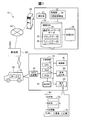
- FIG. 1 is an explanatory diagram for explaining the configuration of a route search system 10 according to the first embodiment of the present invention.
- the route search system 10 includes a route server 20 as a route search device and a car navigation system 50 (car navigation system 50) mounted on the automobile 12.
- the route server 20 and the car navigation system 50 are connected to the Internet INT.
- the car navigation system 50 is connected to the Internet INT wirelessly through the base station BS.
- the route search system 10 is a system for displaying a recommended route from a set departure point to a destination on a display panel 65 provided in the car navigation system 50 so as to be visible.
- the car navigation system 50 includes a GPS receiver 69, a main control unit 51, an operation unit 67, a communication unit 61, an audio output unit 63, and a display panel 65.
- the GPS receiver 69 receives information for specifying the current position (latitude, longitude) of the car navigation system 50 measured using an artificial satellite constituting a GPS (Global Positioning System).
- the display panel 65 includes a liquid crystal display and a drive circuit that drives the liquid crystal display.
- the display panel 65 is not limited to a liquid crystal display, and various display devices such as an organic EL display can be employed.
- the display panel 65 allows the user to visually recognize various information such as a departure place and a destination.
- the search setting screen W1 displayed on the display panel 65 includes an item SL for inputting a departure point, an item DL for inputting a destination, and an item AI for inputting additional information.
- the user inputs each item SL, DL, AI by operating the operation unit 67.
- the additional information is information indicating the degree of accuracy when the route server 20 performs route search. Specifically, this information is information representing a weighting factor ⁇ for a variation value to be described later.
- the search setting screen W1 is configured such that one or a plurality of selection options of “fast”, “normal”, and “accurate” can be selected.
- the relationship between the three selection branches represented in the additional information item AI and the weighting factor ⁇ is as follows.
- Selected branch “early” the weighting factor ⁇ is set to “0”, and the shortest route is selected as a recommended route regardless of the variation value of the average transit time among a plurality of routes from the destination to the departure point. Determined by server 20.
- Selected branch “ordinary” a route in which the weighting factor ⁇ is set to “1”, and among the plurality of routes from the destination to the departure point, a route that places more importance on the variation value than the selected branch “early” is a recommended route As determined by the route server 20.
- the weighting factor ⁇ is not limited to three stages “0”, “1”, and “2”, but may be set by a plurality of integers, or may be set as a continuous numerical value by a bar or the like.
- the audio output unit 63 includes a speaker for outputting audio, a drive circuit for driving the speaker, and the like.
- the communication unit 61 wirelessly performs data communication or voice communication with the base station BS.
- the operation unit 67 is an input device including a numeric keypad, cursor keys, a touch panel, and the like. The operation unit 67 receives input of various information for searching for a route such as a departure point and a destination.
- the main control unit 51 controls the operation of each unit of the car navigation system 50.
- the main control unit 51 includes a CPU 52, a RAM 54, and a ROM 56.
- the CPU 52 implements functions for executing various processes by loading the program stored in the ROM 56 into the RAM 54 and executing the program.
- the main control unit 51 controls the display panel 65 to display a map image, a recommended route, a current position, and the like.
- the main control unit 51 controls the communication unit 61 to communicate with the route server 20 via the base station BS.
- the main control unit 51 may measure the current position information of the car navigation system 50 using the GPS via the GPS receiver 69 at regular time intervals and generate information representing the departure place.
- the route server 20 searches for a route from the departure point designated by the car navigation system 50 to the destination, and sends output information representing the search result to the car navigation system 50 via the Internet INT. It is a server to do.
- the search for the route from the departure place to the destination executed by the route server 20 is referred to as route search processing.
- the route server 20 includes a communication unit 21, a control unit 22, a route database 23 (also referred to as a route DB 23) as a storage unit (storage device), and a map database 28 (also referred to as a map DB 28).
- the communication unit 21 communicates with the car navigation system 50 via the Internet INT.
- the control unit 22 controls the operation of the route server 20.
- the route DB 23 includes road network data 24 that represents a road network on a map as a network.
- the road network data 24 includes link data 25 and node data 26.
- the node data 26 defines a plurality of nodes indicating reference points on the road.
- the link data 25 defines a plurality of links that connect a plurality of nodes defined in the node data 26. Details of the link data 25 and the node data 26 will be described later.
- map data supplied to the car navigation system 50 is stored in a vector data format.
- the map data may be stored in a raster data format such as a bitmap format or JPEG format instead of the vector format.
- This map data includes data representing the shape of features such as topography, buildings, and roads.
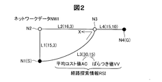
- FIG. 2 is an explanatory diagram of the road network data NW1 indicating a predetermined range of roads as a specific example of the road network data 24.
- the road network data NW1 is data representing road arrangement using links and nodes. In the following description, when a node in the figure is indicated individually, a symbol with an alphabetic character “N” followed by a number is used, and when a link in the figure is indicated individually, an alphabetic character “L” is indicated. A code with a number after it is used.
- FIG. 2 shows four nodes N1 to N4 and four links L1 to L4. Nodes N1 to N4 represent characteristic reference points on roads and lanes. Examples of the reference point include an intersection, a branch point, and a point whose width changes.
- the links L1 to L4 represent roads and lanes connecting the nodes N1 to N4.
- route search information RSI used for searching for a route from the departure point S to the destination point G is defined correspondingly.
- the route search information RSI includes an average cost value AC that represents the average of the passage times of the links L1 to L4, and a variation value VV that represents the degree of variation in the passage times.
- the average cost value AC is calculated from a histogram which is data representing the passage time on the horizontal axis and the occurrence probability (%) for each passage time on the vertical axis. In the present embodiment, this histogram is generated based on probe data collected from the probe car via the network 40.
- the variation value VV is a variance calculated from a histogram. In other embodiments, a standard deviation or the like may be used instead of the dispersion value VV.
- the first numerical value given in parentheses for each of the links L1 to L4 is the average cost value AC
- the second numerical value is the variation value VV.
- the road network data NW1 defines regulation information related to traffic regulation.
- the restriction information includes information indicating prohibition of a left turn from the link L3 to the link L2.
- FIG. 3 is an explanatory diagram showing a detailed configuration of the link data 25 in the road network data 24.
- the link data 25 includes link attribute data 34 indicating attributes for each link.
- the link attributes shown in the link attribute data 34 include a link number, a start point node, an end point node, an average cost value AC, and a variation value VV.
- the link number in the link attribute data 34 is a unique number assigned to each link in order to identify the link.
- the starting point node of the link attribute data 34 represents a code for identifying the node to which the link is connected as the starting point.
- the end point node of the link attribute data 34 represents a code for identifying the node to which the link is connected as the end point.
- the average cost value AC of the link attribute data 34 represents the average of the transit time of the link.
- the variation value VV of the link attribute data 34 represents the degree of variation in the link passage time.
- the example shown in FIG. 3 shows the detailed contents of the link attribute data 34 relating to the link L2 to which the link number “L2” is assigned. Specifically, the link L2 is connected from the “start node N2” to the “end node N3”, the average cost value AC of the link L2 is 16 minutes, and the variation value VV of the link L2 is 3. Has been.
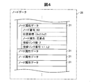
- FIG. 4 is an explanatory diagram showing a detailed configuration of the node data 26 in the road network data 24.
- the node data 26 includes node attribute data 31 indicating an attribute for each node.
- the node attributes shown in the node attribute data 31 include a node number, a position coordinate, a node type, the number of connection links, and a connection link number.
- the node number of the node attribute data 31 is a unique number assigned to each node in order to identify the node.
- the position coordinates of the node attribute data 31 represent the position of the node on the map.
- the node type of the node attribute data 31 represents the type of the reference point represented by the node.
- the number of connected links in the node attribute data 31 indicates the number of links connected to the node.
- the connection link number in the node attribute data 31 is information for identifying a link connected to the node.
- the example shown in FIG. 3 shows the detailed contents of the node attribute data 31 related to the node N2 to which the node number “N2” is assigned.
- the node N2 is located on the coordinates “Xn2 (longitude), Yn (latitude)”, the node N2 represents “intersection”, the number of links connected to the node N2 is “2”, and the connection It is indicated that the number of the link to be “L1, L2”.
- FIG. 5 is a flowchart of route search processing executed by the route search unit 29 of the route server 20.
- the route search process is started when the route server 20 receives the execution start information of the route search process from the car navigation system 50.
- the execution start information includes point information indicating the starting point and destination set by the user using the car navigation system 50, and coefficient information indicating the weighting coefficient ⁇ . That is, the user inputs additional information representing the departure point, the destination, and the weighting factor ⁇ using the car navigation system 50, and instructs the route server 20 to start the route search process using the operation unit 67.
- the information representing the departure place may be automatically generated based on the information representing the departure place received by the GPS receiver 69 of the car navigation system 50, instead of being generated by the user input.
- the route search unit 29 sets the coordinates of the departure point and the destination coordinate used for the route search process based on the point information included in the execution start information included in the execution start information (step S12). After step S12, based on the coordinates of the starting point and the coordinates of the destination, the starting point S that is the starting point of the route and the destination point G that is the ending point in performing the route searching process are set (step S14). .
- the node N1 is set as the departure point S and the node N4 is set as the destination point G is shown.
- the route search unit 29 determines, as a recommended route, a route from which the total cost value of the route passing through the route from the departure point S to the destination point G is minimized.
- the total cost value is calculated based on the integrated value of the average cost value AC corresponding to the link that has passed from the departure point S to the destination point G, and the integrated value of the weighting factor ⁇ and the variation value VV that corresponds to the link that has passed. It is a value obtained by adding the corrected value.
- the total cost value is determined using the following formula (1).
- A is an average cost value AC for each link of the route from the departure point S to the destination point G
- ⁇ is a weighting factor
- V is a variation value VV for each link of the route from the departure point S to the destination point G.
- the route search unit 29 sets the departure point information of the departure point S (step S16).
- the departure point information is an average cost value AC and a variation value VV from the departure point S to the next node.
- both the average cost value AC and the variation value VV are set to zero.
- the average cost value AC and the variation value VV corresponding to the link where the departure point S exists are calculated using the distance from the start point to the end point of the link and the distance from the departure point S to the end point. Set by calculating by proration using the ratio with the distance. In the present embodiment, both the average cost value AC and the variation value VV at the departure point S are set to zero.
- a weighting factor ⁇ is set (step S17).
- the weighting factor ⁇ is set based on coefficient information representing the weighting factor ⁇ included in the execution start information supplied from the car navigation system 50.
- an arbitrary one weighting factor ⁇ is set first and the subsequent steps are performed.
- the route search unit 29 After step S17, the route search unit 29 generates a candidate label that serves as an index for determining a link that passes through the route from the departure point S to the destination point G (step S18).
- the candidate label is generated for a certain link located in the middle of the route from the departure point S to the destination point G, the candidate label is set to the end point (node) of the certain link.
- the candidate label includes an integrated value of the average cost value AC for each link from the departure point S to a certain link, and an integrated value of the variation value VV for each link from the departure point S to a certain link.
- a candidate total cost value is calculated based on information included in the candidate label. Specifically, the candidate total cost value is calculated using the following equation (2).
- A1 is an average cost value AC for each link of a route from the departure point S to a predetermined node that is an end point on the way
- ⁇ is a weighting factor
- V1 is a predetermined value that is an end point on the way from the start point S. It is the variation value VV for each link passing through to the node.
- a candidate label having a candidate total cost value having the smallest value among at least one candidate total cost value is determined as a confirmed label (step S20).
- a route (intermediate route) to a node (provisionally confirmed node) located in the middle of the route from the departure point S to the destination point G is confirmed.
- the node (final node) that is the final link or the end point of the final link when going to the destination point G constituting the halfway route is the link or node where the destination point G is located (step) S22).
- the midway route is determined as the recommended route.
- the output information includes information representing a recommended route from the departure point S to the destination point G, information representing the average passage time from the departure point S to the destination point G, and variation representing variation with respect to the average passage time. Information. Details of the output information will be described later.
- a candidate label is generated by further extending the search branch from the end point of the route to the destination point G using the Dijkstra method. (Step S18). And the process after step S20 is performed again. If it is determined that the recommended route is not fixed for all the weighting factors ⁇ included in the execution start information, the route search unit 29 uses the weighting factor ⁇ for which the recommended route is not fixed in step S17. Run the process again.
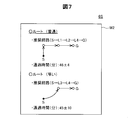
- FIG. 6 is a specific example of the route search process.
- the steps shown in FIG. 6 correspond to the steps shown in FIG. Further, the sub-steps shown in FIG. 6 indicate specific processing executed at the time of each step shown in FIG.
- the example shown in FIG. 6 is a specific example of the route search process when the route search unit 29 sets the node N1 shown in FIG. 2 as the departure point S and the node N4 shown in FIG. It is assumed that the weighting factor ⁇ is set to “1” in step S17.
- Sub-steps C1 and C2 correspond to steps S14 and S16, respectively.
- the route search unit 29 extends a search branch from the departure point S to the destination point G by the Dijkstra method.
- the route search unit 29 (FIG. 1) refers to the node data 26 and the link data 25, and sets candidate labels from the departure point S to the end point of the next link as shown in FIG. S18).
- the most recent links from the node N1 that is the departure point S to the destination point G are the link L1 and the link L3.
- the route search unit 29 sets a candidate label T1 for a route from the departure point S to the end point of the link L1 (specifically, the end point of the link L1).
- a candidate total cost value V1 is calculated based on the candidate label T1.
- the route search unit 29 sets a candidate label T2 for the route from the departure point S to the end point of the link L3 (substep C4).
- the route search unit 29 calculates a candidate total cost value V2 based on the candidate label T2.
- the candidate total cost value of the route from the departure point S to the next node N2 is calculated using the above equation (2). Specifically, the average cost value AC “15” set for the link L1 is added to the average cost value AC “0” set for the departure point S, thereby integrating the average cost value AC (cost integrated value). ) "15" is calculated. Further, in sub-step C3, the variation value VV “3” set in the link L1 is added to the variation value VV “0” set in the departure point S, thereby integrating the variation value VV (dispersion integrated value). “3” is calculated.
- the route search unit 29 calculates a candidate total cost value V1 obtained by adding a correction value that is a product of the positive square root of the variance integration value “3” and the weighting coefficient ⁇ to the cost integration value “15”.
- the calculated candidate total cost value V1 is “16.4”.
- the second decimal place is rounded off when calculating the candidate total cost value.
- the candidate total cost value of the route from the departure point S to the next node N3 is calculated using the above equation (2).
- the cost integrated value “30” is calculated by adding the average cost value AC “30” set to the link L1 to the average cost value AC “0” set to the departure point S.
- the dispersion integrated value “15” is calculated by integrating the dispersion value “15” set in the link L3 with the dispersion value VV “0” set in the departure point S.
- the route search unit 29 adds the correction value that is the product of the positive square root of the dispersion integrated value “15” and the weighting factor ⁇ to the cost integrated value “30”.
- a cost value V2 is calculated.
- the calculated candidate total cost value V2 is “37.7”.
- the candidate label having the minimum total cost value among the candidate total cost values V1 and V2 is determined as a confirmed label.
- the candidate label having the candidate total cost value V1 is confirmed as a confirmed label.
- the route from the departure point S to the link L1 is determined as an intermediate route.
- the search branch is further extended using the Dijkstra method to generate candidate labels (sub Step C6).
- the link L2 from the node N2 to the destination point G is determined with reference to the node data 26 and the link data 25, and in the route from the departure point S to the link L1 and the link L2 via the node N2.
- Candidate label T3 is generated.
- the above equation (2) is used similarly to the substeps C3 and C4.
- the candidate total cost value V3 of the candidate label T3 generated in the sub-step C6 is “35.9”.
- the candidate label T3 having the candidate total cost value V3 is set to the end point (node N3) of the link L2.
- the candidate total cost values V2 and V3 of the two candidate labels T2 and T3 are compared, the candidate label T3 having the minimum candidate total cost value V3 is determined as a confirmed label, and the candidate label T2 is deleted.
- the route from the departure point S to the node N3 via the link L1, the node N2, and the link L2 is determined as an intermediate route.
- the search branch is further extended by the Dijkstra method to generate a candidate label T4 (substep) C8).
- the link L4 from the node N3 to the destination point G is determined with reference to the node data 26 and the link data 25, and from the departure point S via the link L1, the node N2, the link L2, and the node N3.
- the candidate label T4 in the route to the link L4 is generated. Only one candidate label T4 is generated by extending the search branch from the confirmed label determined in the previous sub-step C7, and no other candidate label exists.
- the route search unit 29 determines the candidate label T4 as a confirmed label. As a result, the route from the departure point S to the link L4 having the candidate label T4 determined as the confirmed label is confirmed as an intermediate route. Since the destination point G is the node N4, the destination point G is located at the link L4 or the end point (node N4) of the link L4 on the determined halfway route. Therefore, the midway route determined in substep C8 is determined as a recommended route from the departure point S to the destination point G (substep C9). In sub-step C9, the route search unit 29 refers to the link data 25 and accumulates the average cost value AC corresponding to the links L1, L2, and L4 constituting the recommended route, thereby calculating the average passage time of the recommended route.
- the average passing time is “46 minutes”.
- the route search unit 29 refers to the link data 25 and calculates an integrated value (variation integrated value) of variation values corresponding to L1, L2, and L4 constituting the recommended route. Then, the positive square root of the integrated variation value is set as a variation index (standard deviation) representing the degree of variation in the average transit time. In this embodiment, the variation index is “4”.
- FIG. 7 is an explanatory diagram of the output information screen W2 displayed on the display panel 65.
- the output information screen W2 includes the recommended route determined for each weighting factor ⁇ and the passage time.
- the recommended route is represented by adding a mark such as a red line on the map data.
- the transit time is represented by the average transit time and the standard deviation. Specifically, in the “route (ordinary)” having the weighting factor ⁇ of “1”, the passage time is expressed by an equation (46 ⁇ 4) obtained by adding / decreasing the standard deviation “4” to 46 minutes of the average passage time.
- the user starts route guidance by the car navigation system 50 by selecting one of the two recommended route routes (usually fast).
- the route from the departure point S representing the departure point to the destination point G representing the destination is based on the average cost value AC, the variation value VV, and the weighting factor ⁇ . Determined as a recommended route.
- a flexible route search can be performed by changing the value of the weighting factor ⁇ .
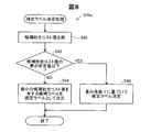
- FIG. 8 is a flowchart of route search processing in the second embodiment of the present invention.
- the difference between the route search process of the second embodiment and the route search process (FIG. 5) of the first embodiment is the content of the process step of determining a candidate label as a confirmed label. Therefore, in FIG. 8, the detailed content of the process (step S20a) which determines a definite label among the processes of a route search process is shown. Since the other steps and the configuration of the route search system 10 are the same as those in the first embodiment, description thereof will be omitted.
- step S20 of the first embodiment the label having the smallest value among the candidate total cost values is determined as the confirmed label.
- step S20a of the second embodiment when the predetermined condition is satisfied, the label is set. A definitive label is determined based on the weighting factor ⁇ . Details will be described below.
- step S20a first, the candidate total cost values of the generated candidate labels are compared (step S40). Next, when there are a plurality of candidate total cost values, it is determined whether or not the difference between the candidate total cost values is equal to or less than a predetermined value (step S42).
- a predetermined value is set to “0.2”. The predetermined value may be “0” or a numerical value other than 0.2.
- the candidate label having the minimum candidate total cost value is determined as a confirmed label (step S44).
- a confirmed label is determined based on the weighting factor ⁇ (step S46).
- a candidate label having a minimum cost integrated value (the first term on the right side of Expression (2)) among a plurality of candidate labels is determined as a confirmed label
- the candidate label having the smallest variation integrated value is determined as the confirmed label.
- the case where the weighting factor ⁇ is “0” or “1” corresponds to the first case
- the case where the weighting factor ⁇ is “2” corresponds to the second case.
- the recommended route from the departure point S to the destination point G can be determined flexibly based on the set weight coefficient ⁇ .
- the average cost value AC is more important than the variation value VV, and a route with a small integrated value of the average cost value AC is set as a recommended route, and the weighting factor is smaller than in the first case.
- the variation value VV is more important than the average cost value AC, and a route having a small variation value integrated value can be determined as a recommended route.
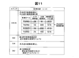
- FIG. 9 is a flowchart of route search processing according to the third embodiment of the present invention.
- FIG. 10 is a first diagram for explaining the flowchart of FIG.
- FIG. 11 is a second diagram for explaining the flowchart of FIG. 9.
- FIG. 12 is a third diagram for explaining the flowchart of FIG. 10 and 12 show road network data NW2 used for explaining the third embodiment.
- the node N6 is set as the departure point S
- the node N30 is set as the destination point G
- the network data NW2 also shows nodes N6 to N11 connecting the links L5 to L14.
- the differences between the route search process of the third embodiment and the route search process (FIG. 5) of the first embodiment are the contents of the processing step for determining a candidate label as a confirmed label and the case where the destination point G is reached. This is a recommended route determination process. Therefore, in FIG. 9, the detailed content of the process (step S20b) which determines a definite label among the processes of a route search process is shown. Of the other steps of the third embodiment, descriptions of steps similar to those of the first embodiment are omitted.
- the configuration of the route search system 10 (FIG. 1) is the same as that of the first embodiment.
- step S20b of the third embodiment in addition to the first candidate label having the smallest candidate total cost value among the plurality of candidate labels, the second candidate label satisfying a predetermined condition is also determined as the confirmed label.
- the weighting factor ⁇ is set to “2”.
- routes R5 to R8 (way route candidates) from the departure point S to the node N10.
- Candidate labels T5 to T8 corresponding to R5 to R8) are set in the node N10.
- step S20b first, the candidate total cost values of the generated candidate labels T5 to T8 (FIG. 10) are compared (step S52), and the minimum candidate total cost among a plurality of candidate total cost values is compared.
- a candidate label having a value is determined as a first candidate label (step S54).
- the candidate label T5 having the candidate total cost value “35.0” is determined as the first candidate label, so that the route R5 corresponding to the candidate label T5 is the first intermediate route candidate R5. It is determined (step S54).
- the route search unit 29 determines whether or not there is a next halfway route candidate (step S56).
- the next halfway route candidate has the first halfway route candidate R5 among the halfway route candidates R6 to R8 (the remaining halfway route candidates R6 to R8) other than the first halfway route candidate R5.
- the route candidate has a cost integrated value smaller than the cost integrated value.
- all the cost integrated values “18, 19, 25” of the candidate labels T6 to T8 are smaller than the cost integrated value “29” of the candidate label T5, it corresponds to the candidate labels T6 to T8.
- the midway route candidates R6 to R8 to become the next way midway route candidates R6 to R8.
- the candidate labels T6 to T8 corresponding to the next way route candidates R6 to R8 are compared (step S58), and the candidate label having the minimum candidate total cost value is determined as the second candidate label (step S60).
- the candidate label T7 having the candidate total cost value “47.3” is determined as the second candidate label, so that the route R7 corresponding to the candidate label T7 is the second intermediate route candidate R7. It is determined (step S60).
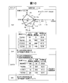
- the route search unit 29 executes the process of step S56 with the intermediate route candidates R6 and R8 other than the already determined first and second intermediate route candidates R5 and R7 as the remaining intermediate route candidates R6 and R8.
- the route search unit 29 uses the second halfway route candidate R7 decided immediately before the process of step S56 as the first halfway route candidate R7. Then, it is determined whether there is a route candidate having a cost integrated value smaller than the cost integrated value “19” of the first midway route candidate R7. In the example shown in FIG. 11, since the cost integrated value “18” of the candidate label T6 is smaller than the cost integrated value “19” of the candidate label T7, the midway route candidate R6 corresponding to the candidate label T6 is the next halfway route.
- Candidate R6 since the cost integrated value “18” of the candidate label T6 is smaller than the cost integrated value “19” of the candidate label T7, the midway route candidate R6 corresponding to the candidate label T6 is the next halfway route.
- route search part 29 performs the process of step S58, S60 shown in FIG. As shown in FIG. 11, since there is only one next way route candidate R6, the next way route candidate R6 is determined as the second way route candidate R6 (steps S58 and S60).
- the route search unit 29 sets the intermediate route candidate R8 other than the previously determined first and second intermediate route candidates R5 to R7 as the remaining intermediate route candidate R8 and repeats the process of step S56.
- the cost integrated value “25” of the candidate label T8 corresponding to the remaining halfway route candidate R8 is the cost integrated value “25” of the candidate label T6 corresponding to the second halfway route candidate R6 determined in the immediately preceding process. Greater than 18 ". Therefore, as shown in FIG. 9, the route search unit 29 determines “NO” in step S56, and determines candidate labels T5 to T7 determined by the processing so far as finalized labels.
- the first and second halfway route candidates R5 to R7 corresponding to the confirmed labels T5 to T7 are determined as the halfway routes R5 to R7 (step S62).
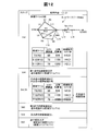
- the route search unit 29 generates candidate labels T9 to T11 by extending search branches from the intermediate routes R5 to R7 corresponding to the confirmed labels T5 to T7 toward the destination point G. Then, the route search unit 29 executes the processes of steps S52 to S62 again for the candidate labels T9 to T11.
- the candidate label T11 having the smallest candidate total cost value is determined, so that the route R11 corresponding to the candidate label T11 is the first halfway route candidate. Determined as R11.
- the process of step S56 is performed. In the example illustrated in FIG.
- step S56 the route candidate R10 having a cost accumulated value smaller than the cost accumulated value “79” of the first midway route candidate R11 (next-point halfway route candidate R10). Therefore, “YES” is determined in step S56.
- steps S58 and S60 are executed.
- the next halfway route candidate R10 is determined as the second halfway route candidate R10.
- the route search unit 29 executes the process of step S56 again with the already determined intermediate route candidate R9 other than the first and second intermediate route candidates R11 and R10 as the remaining intermediate route candidate R9.
- the cost integrated value “89” of the candidate label T8 corresponding to the remaining halfway route candidate R9 is the cost integrated value “89” of the candidate label T10 corresponding to the second halfway route candidate R10 determined in the immediately preceding process. Greater than 78 ". Therefore, as shown in FIG. 9, the route search unit 29 determines “NO” in step S ⁇ b> 56 and determines the candidate labels T ⁇ b> 11 and T ⁇ b> 11 determined by the processing so far as the confirmed labels.
- the first and second halfway route candidates R11 and R10 corresponding to the confirmed labels T11 and 10 are determined as the halfway routes R11 and R10 (step S62).
- the route search unit 29 determines a route on the way, the last link or the node (final node) that is the end point of the last link when going to the destination point G constituting the route is the link where the destination point G is located. Or it is judged whether it is a node (step S22 of FIG. 5). When it is determined that the final link or final node is the link or node where the destination point G is located, the midway route is determined as the recommended route.
- the route search unit 29 has the smallest candidate total cost value among the plurality of intermediate routes.
- the recommended route For example, in the network data NW2 shown in FIG. 12, when the node N11 is set as the destination point G, the intermediate route R10 having the minimum candidate total cost value is selected from the intermediate routes R10 and R11 determined in step S62. Confirm as the recommended route.
- the first candidate label having the smallest candidate total cost value is the candidate label T5, but when the search branch is extended as shown in FIG.
- One candidate label is a candidate label T11.
- the candidate label T11 is a label obtained by extending the search branch from the candidate label T7 in FIG. That is, when only the label having the minimum candidate comprehensive cost value is determined as the definite label and the search branch is extended, a route having the minimum candidate total cost value may not be determined as the recommended route.
- a predetermined condition is selected among candidate labels having a cost integrated value smaller than the first candidate label.
- a candidate label to be satisfied (second candidate label) is also determined as a definitive label. As a result, it is possible to more accurately determine the route having the minimum total cost value as the recommended route.
- Steps S52 and S54 correspond to the “first determination step”.
- Steps S56 to S60 correspond to the “second determination step”.
- Steps S56 to S60 performed after step S60 correspond to the “third determination step”.
- the variation index is calculated by taking the positive square root of the variation integrated value. Instead, the average cost value AC of each link constituting the recommended route or the intermediate route is calculated.
- Statistical information representing a histogram used in the process may be used. Specifically, the statistical information of each link may be subjected to a convolution operation, and the standard deviation calculated from the statistical information representing the histogram after the convolution operation may be used as the variation index. Moreover, you may use the average cost value calculated from the statistical information showing the histogram after a convolution calculation, when determining a recommended path
- FIG. 13 is a conceptual diagram of the convolution operation. In the example of FIG.
- the link data 25 defines data (statistical information) representing the histograms H10, H12, and H14 in addition to the link number, start point node, end point node, average cost value AC, and variation value VV.
- the histograms H10, H12, and H14 are generated based on, for example, probe data collected from a probe car, and the horizontal axis represents the link passage time (minutes) and the vertical axis represents the occurrence probability (%) for each passage time. .
- the histogram of the latest link L10 and the next link L12 from the departure point S to the destination point G is convolved to generate a new histogram H18.
- the histogram H14 of the link L14 which is the next link of the link L12, and the histogram 18 are convolved to generate a new histogram H20.
- a standard deviation is obtained from statistical information representing the histograms H18 and H20 generated by the convolution operation.
- the above histogram convolution operation is defined by the following equation (3).
- F (m) on the left side is a function generated by performing a convolution operation on two histograms
- f is a function defined by the first histogram
- g is the second histogram.
- n represents the passage time in the first histogram
- m represents the passage time (total time) when the first and second histograms are convolved.
- the variation index with respect to the passage time in the recommended route or the intermediate route can be calculated as the standard deviation. Further, by calculating the standard deviation from the statistical information represented by the histogram after the convolution calculation, it is possible to calculate a more accurate variation index with a reduced error compared to the above embodiment.
- the step of determining a halfway route using the statistical information represented by the histogram after the convolution operation in the first modification is performed as follows.
- the route search unit 29 (FIG. 1) convolves each statistical information representing each histogram of the transit time of each link that passes through the halfway route candidate that is a halfway route candidate, thereby passing through each halfway route candidate.
- Candidate statistical information representing a histogram of time is generated.
- the route search unit 29 calculates a candidate average cost value At1 representing the average transit time of the halfway route candidate calculated from the candidate statistical information and a candidate variation value VV representing the degree of variation of the halfway route candidate (distributed in this modification). And a candidate total cost value of each halfway route candidate according to a function including the weighting factor ⁇ .
- the route search unit 29 calculates a candidate total cost value using the following equation (4).
- At1 is a candidate average cost value calculated from the candidate statistical information
- ⁇ is a weighting factor
- Vt1 is a candidate variation value VV (variance) calculated from the candidate statistical information.
- the right side of the above equation (4) is defined by the first term indicating the candidate average cost value and the second term indicating the correction value obtained by multiplying the positive square root of the candidate variation value VV and the weighting factor ⁇ .
- the present invention is not limited to this.
- the second term may be a product of the candidate variation value VV and the weighting factor ⁇ .
- the right side of the above formula (4) may include terms such as the third term and the fourth term.
- the third term defines a term for increasing the cost value as traffic jam information when there is traffic on a specific link.
- the candidate variation value VV calculated from the candidate statistical information after the convolution calculation is used when calculating the candidate total cost value
- the candidate total cost value using the more accurate variation value VV with reduced error is used. Can be used to determine the route.
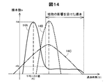
- FIG. 14 is a diagram for explaining a method of calculating the average cost value AC and the variation value VV in a certain link L.
- a graph 14A in FIG. 14 is a graph generated based on the probe data, and the horizontal axis represents the passage time (minutes) of the link L, and the vertical axis represents the number of samples n (occurrence probability) for each passage time. The occurrence probability is calculated based on the number of samples.
- the graph 14B is a normal distribution based on the average value of the information (original information) represented by the graph 14A and the variation value obtained from the information after deleting the passage time estimated to be affected by the feature from the graph 14A.
- the graph 14C is an image diagram of a normal distribution based on information (original information) represented by the graph 14A.
- the link L (specific link L) has a specific feature that affects a transit time such as a signal or a level crossing, or a link adjacent to the specific link L indicates a specific feature such as a signal or a level crossing.
- the specific feature is affected by an increase in the transit time of the specific link L at a certain frequency.
- the average cost value AC and the variation value VV of the specific link L are as follows. It may be calculated. That is, the average cost value AC is a value calculated using all the transit time data represented by the original information graph 14A and its occurrence probability.
- the variation value VV is calculated based on the passage time data estimated to have passed without being affected by a specific feature among all the data represented by the original information graph 14A and the occurrence probability thereof.
- the “Data estimated to have passed due to the influence of a specific feature” means, for example, the number of samples corresponding to the average cost value AC among the data having a longer transit time than the average cost value AC. This is data having a longer passage time than the shortest passage time that is less than or equal to a predetermined ratio of na (for example, 10% or less).
- the “data estimated to have passed under the influence of a specific feature” may be data (for example, data of the top 10%) whose passage time in the number of samples n is longer than a predetermined ratio. .
- data for example, data of the top 10%
- the variation value VV is calculated.
- the normal distribution (graph 14C) based on all data of the original information has an excessive variation value VV
- the normal distribution (graph) based on the information after deleting the data estimated to be affected by the feature. 14B) is appropriately corrected without the variation value VV being excessive.
- the average cost value AC can accurately represent the transit time data of the original information, and can correct an excessive variation value due to being affected by the feature.
- the route server 20 performs the route search process, and the output information is displayed on the display panel 65 when the car navigation system 50 receives the output information.
- the output information can be displayed on the display panel 65 in various ways.
- the route server 20 transmits network data of a necessary range including a departure place and a destination to the car navigation system 50, and the car navigation system 50 that has received the network data performs route search processing and displays output information on the display panel 65. Also good.
- the car navigation system 50 may notify the user of the output information by voice.
- the function as the route server 20 may be mounted on the car navigation system 50 itself.
- the total cost value and the candidate total cost value are calculated using the relational expressions (1) and (2). That is, the second term on the right side of the expressions (1) and (2) is obtained by multiplying the weight coefficient ⁇ by a value (specifically, a positive square root) having a positive correlation with the integrated value of the variation value VV. Yes.
- the present invention is not limited to the above formulas (1) and (2), and the total cost value and the candidate total cost value may be calculated using a function including the average cost value AC, the variation value VV, and the weighting factor ⁇ .
- the second term on the right side of the above equation (1) may be changed to a term obtained by multiplying the integrated value of variation values by a weighting factor.
- the right side of the above formulas (1) and (2) may include terms such as the third term and the fourth term.
- the third term defines a term for increasing the cost value as traffic jam information when there is traffic on a specific link.
- the present invention is not limited to the above-described embodiments and modifications, and can be realized with various configurations without departing from the spirit thereof.
- the technical features in the embodiments and the modifications corresponding to the technical features in each embodiment described in the summary section of the invention are to solve some or all of the above-described problems, or In order to achieve part or all of the effects, replacement or combination can be performed as appropriate. Further, if the technical feature is not described as essential in the present specification, it can be deleted as appropriate.
Priority Applications (3)
| Application Number | Priority Date | Filing Date | Title |
|---|---|---|---|
| EP15754445.3A EP3112808B1 (de) | 2014-02-27 | 2015-02-19 | Routensuchvorrichtung, routensuchverfahren und programm |
| CN201580010574.XA CN107949770B (zh) | 2014-02-27 | 2015-02-19 | 路径搜索装置、路径搜索方法及程序 |
| US15/121,576 US10578446B2 (en) | 2014-02-27 | 2015-02-19 | Route search apparatus, route search method and computer-readable storage medium storing program |
Applications Claiming Priority (2)
| Application Number | Priority Date | Filing Date | Title |
|---|---|---|---|
| JP2014036275A JP6298322B2 (ja) | 2014-02-27 | 2014-02-27 | 経路探索装置、経路探索方法およびプログラム |
| JP2014-036275 | 2014-02-27 |
Publications (1)
| Publication Number | Publication Date |
|---|---|
| WO2015129214A1 true WO2015129214A1 (ja) | 2015-09-03 |
Family
ID=54008551
Family Applications (1)
| Application Number | Title | Priority Date | Filing Date |
|---|---|---|---|
| PCT/JP2015/000798 WO2015129214A1 (ja) | 2014-02-27 | 2015-02-19 | 経路探索装置、経路探索方法およびプログラム |
Country Status (5)
| Country | Link |
|---|---|
| US (1) | US10578446B2 (de) |
| EP (1) | EP3112808B1 (de) |
| JP (1) | JP6298322B2 (de) |
| CN (1) | CN107949770B (de) |
| WO (1) | WO2015129214A1 (de) |
Families Citing this family (9)
| Publication number | Priority date | Publication date | Assignee | Title |
|---|---|---|---|---|
| EP3114574A4 (de) * | 2014-03-03 | 2018-03-07 | Inrix, Inc. | Verkehrsbehinderungsnachweis |
| US20170011312A1 (en) * | 2015-07-07 | 2017-01-12 | Tyco Fire & Security Gmbh | Predicting Work Orders For Scheduling Service Tasks On Intrusion And Fire Monitoring |
| US10108150B1 (en) * | 2015-08-28 | 2018-10-23 | Google Llc | Waking user up in time to arrive at appointment by calculating bed-to-door time |
| US9576490B1 (en) * | 2016-02-08 | 2017-02-21 | GM Global Technology Operations LLC | Personalized navigation route for transportation device |
| JP6813407B2 (ja) * | 2017-03-28 | 2021-01-13 | アイシン・エィ・ダブリュ株式会社 | 経路探索装置及びコンピュータプログラム |
| JP7243820B2 (ja) * | 2019-05-27 | 2023-03-22 | 日本電信電話株式会社 | 移動人数推定装置、移動人数推定方法、及び移動人数推定プログラム |
| US11871114B2 (en) * | 2019-10-04 | 2024-01-09 | Visit Inc. | System and method for producing panoramic image content |
| CN111682975B (zh) * | 2020-04-24 | 2023-05-16 | 视联动力信息技术股份有限公司 | 网络状态预测方法、装置、电子设备及存储介质 |
| US20220026222A1 (en) * | 2020-07-24 | 2022-01-27 | Bayerische Motoren Werke Aktiengesellschaft | Method, Machine Readable Medium, Device, and Vehicle For Determining a Route Connecting a Plurality of Destinations in a Road Network, Method, Machine Readable Medium, and Device For Training a Machine Learning Module |
Citations (1)
| Publication number | Priority date | Publication date | Assignee | Title |
|---|---|---|---|---|
| JP2005091303A (ja) * | 2003-09-19 | 2005-04-07 | Sumitomo Electric Ind Ltd | 経路提供装置及びプログラム |
Family Cites Families (24)
| Publication number | Priority date | Publication date | Assignee | Title |
|---|---|---|---|---|
| JP2002133351A (ja) * | 2000-10-25 | 2002-05-10 | Nec Corp | 最小コスト経路探索装置及びそれに用いる最小コスト経路探索方法 |
| JP4079083B2 (ja) * | 2003-12-12 | 2008-04-23 | トヨタ自動車株式会社 | 車両の制御装置 |
| DE102004032495A1 (de) * | 2004-07-05 | 2006-01-26 | Siemens Ag | Verfahren und Routenplanungssystem zur dynamischen Routenplanung |
| JP4743275B2 (ja) * | 2006-03-01 | 2011-08-10 | トヨタ自動車株式会社 | 自車進路決定方法および自車進路決定装置 |
| US7756021B2 (en) * | 2006-07-26 | 2010-07-13 | Mitsubishi Electric Research Laboratories, Inc. | Method for finding minimal cost paths under uncertainty |
| JP4862621B2 (ja) * | 2006-11-15 | 2012-01-25 | トヨタ自動車株式会社 | ハイブリッド車両およびその制御方法 |
| JP2008241605A (ja) | 2007-03-28 | 2008-10-09 | Aisin Aw Co Ltd | 経路案内装置 |
| JP4903616B2 (ja) * | 2007-03-29 | 2012-03-28 | アイシン・エィ・ダブリュ株式会社 | 地図更新データ供給装置、地図データ更新システム、及び地図更新データ供給方法 |
| JP4825722B2 (ja) * | 2007-04-27 | 2011-11-30 | アイシン・エィ・ダブリュ株式会社 | 経路案内システム、ナビゲーション装置及び経路案内方法 |
| CN101561288B (zh) * | 2009-05-26 | 2011-08-17 | 天津三星光电子有限公司 | 利用数码相机为车辆提供动态路径规划实现导航的方法 |
| EP2746727B1 (de) * | 2009-07-09 | 2016-09-07 | TomTom International B.V. | Verfahren und vorrichtung zur zeitabhängige routenberechnung |
| WO2011013201A1 (ja) * | 2009-07-28 | 2011-02-03 | トヨタ自動車株式会社 | 車両制御装置、車両制御方法及び車両制御システム |
| US8612273B2 (en) * | 2010-04-01 | 2013-12-17 | The Crawford Group, Inc. | Method and system for managing vehicle travel |
| US8868325B2 (en) * | 2010-04-05 | 2014-10-21 | Toyota Jidosha Kabushiki Kaisha | Collision judgment apparatus for vehicle |
| CN102947676B (zh) * | 2010-04-23 | 2016-06-01 | 通腾科技股份有限公司 | 导航装置及在其上实行的方法 |
| US9273968B2 (en) * | 2010-06-23 | 2016-03-01 | Aisin Aw Co., Ltd. | Track information generating device, track information generating method, and computer-readable storage medium |
| JP2012141145A (ja) | 2010-12-28 | 2012-07-26 | Navitime Japan Co Ltd | ナビゲーション装置、ナビゲーションシステム、ナビゲーションサーバ、ナビゲーション方法、および、プログラム |
| JP5641060B2 (ja) * | 2011-01-20 | 2014-12-17 | トヨタ自動車株式会社 | 走行計画生成方法及び走行計画生成装置 |
| WO2012157048A1 (ja) * | 2011-05-13 | 2012-11-22 | トヨタ自動車 株式会社 | 車両用信号情報処理装置及び車両用信号情報処理方法、並びに運転支援装置及び運転支援方法 |
| US9644967B2 (en) * | 2011-07-05 | 2017-05-09 | Toyota Jidosha Kabushiki Kaisha | Recommendation information provision system |
| JP5905691B2 (ja) * | 2011-09-26 | 2016-04-20 | トヨタ自動車株式会社 | 車両用操作入力装置 |
| JP5712915B2 (ja) * | 2011-12-21 | 2015-05-07 | トヨタ自動車株式会社 | プラグインハイブリッド車両 |
| US9346362B2 (en) * | 2012-06-07 | 2016-05-24 | Clarion Co., Ltd. | Energy estimation device, information system for automotive, and server device |
| GB201211614D0 (en) * | 2012-06-29 | 2012-08-15 | Tomtom Dev Germany Gmbh | Generating alternative routes |
-
2014
- 2014-02-27 JP JP2014036275A patent/JP6298322B2/ja active Active
-
2015
- 2015-02-19 US US15/121,576 patent/US10578446B2/en active Active
- 2015-02-19 CN CN201580010574.XA patent/CN107949770B/zh not_active Expired - Fee Related
- 2015-02-19 WO PCT/JP2015/000798 patent/WO2015129214A1/ja active Application Filing
- 2015-02-19 EP EP15754445.3A patent/EP3112808B1/de active Active
Patent Citations (1)
| Publication number | Priority date | Publication date | Assignee | Title |
|---|---|---|---|---|
| JP2005091303A (ja) * | 2003-09-19 | 2005-04-07 | Sumitomo Electric Ind Ltd | 経路提供装置及びプログラム |
Also Published As
| Publication number | Publication date |
|---|---|
| EP3112808A4 (de) | 2017-06-21 |
| JP2015161557A (ja) | 2015-09-07 |
| CN107949770A (zh) | 2018-04-20 |
| EP3112808B1 (de) | 2020-04-08 |
| US10578446B2 (en) | 2020-03-03 |
| JP6298322B2 (ja) | 2018-03-20 |
| EP3112808A1 (de) | 2017-01-04 |
| CN107949770B (zh) | 2021-03-02 |
| US20160363455A1 (en) | 2016-12-15 |
Similar Documents
| Publication | Publication Date | Title |
|---|---|---|
| JP6298322B2 (ja) | 経路探索装置、経路探索方法およびプログラム | |
| US7437240B2 (en) | Navigation system and program for controlling the same | |
| US10352710B2 (en) | Navigation server, navigation client, and navigation method | |
| JP2015161557A5 (de) | ||
| WO2017061135A1 (ja) | 運転快適度算出装置、運転快適度算出方法、および運転快適度算出システム | |
| US20080228389A1 (en) | Route-selection-supporting device, method, and program | |
| JP2005091303A (ja) | 経路提供装置及びプログラム | |
| JP2008249539A (ja) | 地図表示システム、端末装置、地図表示サーバ及び地図表示方法 | |
| US10209088B2 (en) | Method and apparatus for route calculation considering potential mistakes | |
| JP2010043964A (ja) | 計算機システム及び経路案内方法 | |
| CN113706857A (zh) | 道路通行性的确定方法、装置、设备及存储介质 | |
| JP2007033209A (ja) | ナビゲーション装置 | |
| JP5132694B2 (ja) | データ生成装置、データ生成方法及び経路探索装置 | |
| JP7040355B2 (ja) | 情報処理装置及び情報処理方法、プログラム | |
| JP7173310B2 (ja) | 経路探索装置、経路探索方法、及び経路探索プログラム | |
| US10401187B2 (en) | Method, apparatus and computer program product for a navigation system user interface | |
| JP5925103B2 (ja) | 経路探索装置、ナビゲーション装置、経路探索方法、経路探索プログラム、及びナビゲーションプログラム | |
| JP2015224921A (ja) | 推奨ルート探索装置および推奨ルート探索装置用のプログラム | |
| JP2018040727A (ja) | 経路案内装置、経路案内方法、およびコンピュータプログラム | |
| US20220107199A1 (en) | Search device, search method, and storage medium | |
| KR102242422B1 (ko) | 대중교통 경로 탐색 서버 및 방법 | |
| US20220026227A1 (en) | Navigation route determination method, device, and storage medium | |
| JP7159102B2 (ja) | 情報処理装置、情報処理方法および情報処理プログラム | |
| JP2018044902A (ja) | ナビゲーションシステム及びコンピュータプログラム | |
| JP2019124507A (ja) | 経路探索装置、経路探索方法およびコンピュータプログラム |
Legal Events
| Date | Code | Title | Description |
|---|---|---|---|
| 121 | Ep: the epo has been informed by wipo that ep was designated in this application |
Ref document number: 15754445 Country of ref document: EP Kind code of ref document: A1 |
|
| REEP | Request for entry into the european phase |
Ref document number: 2015754445 Country of ref document: EP |
|
| WWE | Wipo information: entry into national phase |
Ref document number: 2015754445 Country of ref document: EP |
|
| WWE | Wipo information: entry into national phase |
Ref document number: 15121576 Country of ref document: US |
|
| NENP | Non-entry into the national phase |
Ref country code: DE |