WO2015129114A1 - ハイブリッド車両の制御装置 - Google Patents
ハイブリッド車両の制御装置 Download PDFInfo
- Publication number
- WO2015129114A1 WO2015129114A1 PCT/JP2014/081420 JP2014081420W WO2015129114A1 WO 2015129114 A1 WO2015129114 A1 WO 2015129114A1 JP 2014081420 W JP2014081420 W JP 2014081420W WO 2015129114 A1 WO2015129114 A1 WO 2015129114A1
- Authority
- WO
- WIPO (PCT)
- Prior art keywords
- internal combustion
- air
- combustion engine
- fuel ratio
- hybrid vehicle
- Prior art date
- Legal status (The legal status is an assumption and is not a legal conclusion. Google has not performed a legal analysis and makes no representation as to the accuracy of the status listed.)
- Ceased
Links
Images







Classifications
-
- B—PERFORMING OPERATIONS; TRANSPORTING
- B60—VEHICLES IN GENERAL
- B60W—CONJOINT CONTROL OF VEHICLE SUB-UNITS OF DIFFERENT TYPE OR DIFFERENT FUNCTION; CONTROL SYSTEMS SPECIALLY ADAPTED FOR HYBRID VEHICLES; ROAD VEHICLE DRIVE CONTROL SYSTEMS FOR PURPOSES NOT RELATED TO THE CONTROL OF A PARTICULAR SUB-UNIT
- B60W20/00—Control systems specially adapted for hybrid vehicles
- B60W20/10—Controlling the power contribution of each of the prime movers to meet required power demand
-
- B—PERFORMING OPERATIONS; TRANSPORTING
- B60—VEHICLES IN GENERAL
- B60K—ARRANGEMENT OR MOUNTING OF PROPULSION UNITS OR OF TRANSMISSIONS IN VEHICLES; ARRANGEMENT OR MOUNTING OF PLURAL DIVERSE PRIME-MOVERS IN VEHICLES; AUXILIARY DRIVES FOR VEHICLES; INSTRUMENTATION OR DASHBOARDS FOR VEHICLES; ARRANGEMENTS IN CONNECTION WITH COOLING, AIR INTAKE, GAS EXHAUST OR FUEL SUPPLY OF PROPULSION UNITS IN VEHICLES
- B60K6/00—Arrangement or mounting of plural diverse prime-movers for mutual or common propulsion, e.g. hybrid propulsion systems comprising electric motors and internal combustion engines
- B60K6/20—Arrangement or mounting of plural diverse prime-movers for mutual or common propulsion, e.g. hybrid propulsion systems comprising electric motors and internal combustion engines the prime-movers consisting of electric motors and internal combustion engines, e.g. HEVs
- B60K6/42—Arrangement or mounting of plural diverse prime-movers for mutual or common propulsion, e.g. hybrid propulsion systems comprising electric motors and internal combustion engines the prime-movers consisting of electric motors and internal combustion engines, e.g. HEVs characterised by the architecture of the hybrid electric vehicle
- B60K6/44—Series-parallel type
- B60K6/445—Differential gearing distribution type
-
- B—PERFORMING OPERATIONS; TRANSPORTING
- B60—VEHICLES IN GENERAL
- B60K—ARRANGEMENT OR MOUNTING OF PROPULSION UNITS OR OF TRANSMISSIONS IN VEHICLES; ARRANGEMENT OR MOUNTING OF PLURAL DIVERSE PRIME-MOVERS IN VEHICLES; AUXILIARY DRIVES FOR VEHICLES; INSTRUMENTATION OR DASHBOARDS FOR VEHICLES; ARRANGEMENTS IN CONNECTION WITH COOLING, AIR INTAKE, GAS EXHAUST OR FUEL SUPPLY OF PROPULSION UNITS IN VEHICLES
- B60K6/00—Arrangement or mounting of plural diverse prime-movers for mutual or common propulsion, e.g. hybrid propulsion systems comprising electric motors and internal combustion engines
- B60K6/20—Arrangement or mounting of plural diverse prime-movers for mutual or common propulsion, e.g. hybrid propulsion systems comprising electric motors and internal combustion engines the prime-movers consisting of electric motors and internal combustion engines, e.g. HEVs
- B60K6/22—Arrangement or mounting of plural diverse prime-movers for mutual or common propulsion, e.g. hybrid propulsion systems comprising electric motors and internal combustion engines the prime-movers consisting of electric motors and internal combustion engines, e.g. HEVs characterised by apparatus, components or means specially adapted for HEVs
- B60K6/36—Arrangement or mounting of plural diverse prime-movers for mutual or common propulsion, e.g. hybrid propulsion systems comprising electric motors and internal combustion engines the prime-movers consisting of electric motors and internal combustion engines, e.g. HEVs characterised by apparatus, components or means specially adapted for HEVs characterised by the transmission gearings
- B60K6/365—Arrangement or mounting of plural diverse prime-movers for mutual or common propulsion, e.g. hybrid propulsion systems comprising electric motors and internal combustion engines the prime-movers consisting of electric motors and internal combustion engines, e.g. HEVs characterised by apparatus, components or means specially adapted for HEVs characterised by the transmission gearings with the gears having orbital motion
-
- B—PERFORMING OPERATIONS; TRANSPORTING
- B60—VEHICLES IN GENERAL
- B60K—ARRANGEMENT OR MOUNTING OF PROPULSION UNITS OR OF TRANSMISSIONS IN VEHICLES; ARRANGEMENT OR MOUNTING OF PLURAL DIVERSE PRIME-MOVERS IN VEHICLES; AUXILIARY DRIVES FOR VEHICLES; INSTRUMENTATION OR DASHBOARDS FOR VEHICLES; ARRANGEMENTS IN CONNECTION WITH COOLING, AIR INTAKE, GAS EXHAUST OR FUEL SUPPLY OF PROPULSION UNITS IN VEHICLES
- B60K6/00—Arrangement or mounting of plural diverse prime-movers for mutual or common propulsion, e.g. hybrid propulsion systems comprising electric motors and internal combustion engines
- B60K6/20—Arrangement or mounting of plural diverse prime-movers for mutual or common propulsion, e.g. hybrid propulsion systems comprising electric motors and internal combustion engines the prime-movers consisting of electric motors and internal combustion engines, e.g. HEVs
- B60K6/22—Arrangement or mounting of plural diverse prime-movers for mutual or common propulsion, e.g. hybrid propulsion systems comprising electric motors and internal combustion engines the prime-movers consisting of electric motors and internal combustion engines, e.g. HEVs characterised by apparatus, components or means specially adapted for HEVs
- B60K6/38—Arrangement or mounting of plural diverse prime-movers for mutual or common propulsion, e.g. hybrid propulsion systems comprising electric motors and internal combustion engines the prime-movers consisting of electric motors and internal combustion engines, e.g. HEVs characterised by apparatus, components or means specially adapted for HEVs characterised by the driveline clutches
- B60K6/383—One-way clutches or freewheel devices
-
- B—PERFORMING OPERATIONS; TRANSPORTING
- B60—VEHICLES IN GENERAL
- B60K—ARRANGEMENT OR MOUNTING OF PROPULSION UNITS OR OF TRANSMISSIONS IN VEHICLES; ARRANGEMENT OR MOUNTING OF PLURAL DIVERSE PRIME-MOVERS IN VEHICLES; AUXILIARY DRIVES FOR VEHICLES; INSTRUMENTATION OR DASHBOARDS FOR VEHICLES; ARRANGEMENTS IN CONNECTION WITH COOLING, AIR INTAKE, GAS EXHAUST OR FUEL SUPPLY OF PROPULSION UNITS IN VEHICLES
- B60K6/00—Arrangement or mounting of plural diverse prime-movers for mutual or common propulsion, e.g. hybrid propulsion systems comprising electric motors and internal combustion engines
- B60K6/20—Arrangement or mounting of plural diverse prime-movers for mutual or common propulsion, e.g. hybrid propulsion systems comprising electric motors and internal combustion engines the prime-movers consisting of electric motors and internal combustion engines, e.g. HEVs
- B60K6/22—Arrangement or mounting of plural diverse prime-movers for mutual or common propulsion, e.g. hybrid propulsion systems comprising electric motors and internal combustion engines the prime-movers consisting of electric motors and internal combustion engines, e.g. HEVs characterised by apparatus, components or means specially adapted for HEVs
- B60K6/38—Arrangement or mounting of plural diverse prime-movers for mutual or common propulsion, e.g. hybrid propulsion systems comprising electric motors and internal combustion engines the prime-movers consisting of electric motors and internal combustion engines, e.g. HEVs characterised by apparatus, components or means specially adapted for HEVs characterised by the driveline clutches
- B60K6/387—Actuated clutches, i.e. clutches engaged or disengaged by electric, hydraulic or mechanical actuating means
-
- B—PERFORMING OPERATIONS; TRANSPORTING
- B60—VEHICLES IN GENERAL
- B60K—ARRANGEMENT OR MOUNTING OF PROPULSION UNITS OR OF TRANSMISSIONS IN VEHICLES; ARRANGEMENT OR MOUNTING OF PLURAL DIVERSE PRIME-MOVERS IN VEHICLES; AUXILIARY DRIVES FOR VEHICLES; INSTRUMENTATION OR DASHBOARDS FOR VEHICLES; ARRANGEMENTS IN CONNECTION WITH COOLING, AIR INTAKE, GAS EXHAUST OR FUEL SUPPLY OF PROPULSION UNITS IN VEHICLES
- B60K6/00—Arrangement or mounting of plural diverse prime-movers for mutual or common propulsion, e.g. hybrid propulsion systems comprising electric motors and internal combustion engines
- B60K6/20—Arrangement or mounting of plural diverse prime-movers for mutual or common propulsion, e.g. hybrid propulsion systems comprising electric motors and internal combustion engines the prime-movers consisting of electric motors and internal combustion engines, e.g. HEVs
- B60K6/50—Architecture of the driveline characterised by arrangement or kind of transmission units
- B60K6/54—Transmission for changing ratio
- B60K6/547—Transmission for changing ratio the transmission being a stepped gearing
-
- B—PERFORMING OPERATIONS; TRANSPORTING
- B60—VEHICLES IN GENERAL
- B60L—PROPULSION OF ELECTRICALLY-PROPELLED VEHICLES; SUPPLYING ELECTRIC POWER FOR AUXILIARY EQUIPMENT OF ELECTRICALLY-PROPELLED VEHICLES; ELECTRODYNAMIC BRAKE SYSTEMS FOR VEHICLES IN GENERAL; MAGNETIC SUSPENSION OR LEVITATION FOR VEHICLES; MONITORING OPERATING VARIABLES OF ELECTRICALLY-PROPELLED VEHICLES; ELECTRIC SAFETY DEVICES FOR ELECTRICALLY-PROPELLED VEHICLES
- B60L50/00—Electric propulsion with power supplied within the vehicle
- B60L50/10—Electric propulsion with power supplied within the vehicle using propulsion power supplied by engine-driven generators, e.g. generators driven by combustion engines
- B60L50/16—Electric propulsion with power supplied within the vehicle using propulsion power supplied by engine-driven generators, e.g. generators driven by combustion engines with provision for separate direct mechanical propulsion
-
- B—PERFORMING OPERATIONS; TRANSPORTING
- B60—VEHICLES IN GENERAL
- B60W—CONJOINT CONTROL OF VEHICLE SUB-UNITS OF DIFFERENT TYPE OR DIFFERENT FUNCTION; CONTROL SYSTEMS SPECIALLY ADAPTED FOR HYBRID VEHICLES; ROAD VEHICLE DRIVE CONTROL SYSTEMS FOR PURPOSES NOT RELATED TO THE CONTROL OF A PARTICULAR SUB-UNIT
- B60W10/00—Conjoint control of vehicle sub-units of different type or different function
- B60W10/04—Conjoint control of vehicle sub-units of different type or different function including control of propulsion units
- B60W10/06—Conjoint control of vehicle sub-units of different type or different function including control of propulsion units including control of combustion engines
-
- B—PERFORMING OPERATIONS; TRANSPORTING
- B60—VEHICLES IN GENERAL
- B60W—CONJOINT CONTROL OF VEHICLE SUB-UNITS OF DIFFERENT TYPE OR DIFFERENT FUNCTION; CONTROL SYSTEMS SPECIALLY ADAPTED FOR HYBRID VEHICLES; ROAD VEHICLE DRIVE CONTROL SYSTEMS FOR PURPOSES NOT RELATED TO THE CONTROL OF A PARTICULAR SUB-UNIT
- B60W10/00—Conjoint control of vehicle sub-units of different type or different function
- B60W10/04—Conjoint control of vehicle sub-units of different type or different function including control of propulsion units
- B60W10/08—Conjoint control of vehicle sub-units of different type or different function including control of propulsion units including control of electric propulsion units, e.g. motors or generators
-
- B—PERFORMING OPERATIONS; TRANSPORTING
- B60—VEHICLES IN GENERAL
- B60W—CONJOINT CONTROL OF VEHICLE SUB-UNITS OF DIFFERENT TYPE OR DIFFERENT FUNCTION; CONTROL SYSTEMS SPECIALLY ADAPTED FOR HYBRID VEHICLES; ROAD VEHICLE DRIVE CONTROL SYSTEMS FOR PURPOSES NOT RELATED TO THE CONTROL OF A PARTICULAR SUB-UNIT
- B60W10/00—Conjoint control of vehicle sub-units of different type or different function
- B60W10/10—Conjoint control of vehicle sub-units of different type or different function including control of change-speed gearings
- B60W10/101—Infinitely variable gearings
- B60W10/105—Infinitely variable gearings of electric type
-
- B—PERFORMING OPERATIONS; TRANSPORTING
- B60—VEHICLES IN GENERAL
- B60W—CONJOINT CONTROL OF VEHICLE SUB-UNITS OF DIFFERENT TYPE OR DIFFERENT FUNCTION; CONTROL SYSTEMS SPECIALLY ADAPTED FOR HYBRID VEHICLES; ROAD VEHICLE DRIVE CONTROL SYSTEMS FOR PURPOSES NOT RELATED TO THE CONTROL OF A PARTICULAR SUB-UNIT
- B60W10/00—Conjoint control of vehicle sub-units of different type or different function
- B60W10/24—Conjoint control of vehicle sub-units of different type or different function including control of energy storage means
- B60W10/26—Conjoint control of vehicle sub-units of different type or different function including control of energy storage means for electrical energy, e.g. batteries or capacitors
-
- B—PERFORMING OPERATIONS; TRANSPORTING
- B60—VEHICLES IN GENERAL
- B60W—CONJOINT CONTROL OF VEHICLE SUB-UNITS OF DIFFERENT TYPE OR DIFFERENT FUNCTION; CONTROL SYSTEMS SPECIALLY ADAPTED FOR HYBRID VEHICLES; ROAD VEHICLE DRIVE CONTROL SYSTEMS FOR PURPOSES NOT RELATED TO THE CONTROL OF A PARTICULAR SUB-UNIT
- B60W20/00—Control systems specially adapted for hybrid vehicles
-
- B—PERFORMING OPERATIONS; TRANSPORTING
- B60—VEHICLES IN GENERAL
- B60W—CONJOINT CONTROL OF VEHICLE SUB-UNITS OF DIFFERENT TYPE OR DIFFERENT FUNCTION; CONTROL SYSTEMS SPECIALLY ADAPTED FOR HYBRID VEHICLES; ROAD VEHICLE DRIVE CONTROL SYSTEMS FOR PURPOSES NOT RELATED TO THE CONTROL OF A PARTICULAR SUB-UNIT
- B60W30/00—Purposes of road vehicle drive control systems not related to the control of a particular sub-unit, e.g. of systems using conjoint control of vehicle sub-units
- B60W30/18—Propelling the vehicle
- B60W30/184—Preventing damage resulting from overload or excessive wear of the driveline
- B60W30/186—Preventing damage resulting from overload or excessive wear of the driveline excessive wear or burn out of friction elements, e.g. clutches
-
- B—PERFORMING OPERATIONS; TRANSPORTING
- B60—VEHICLES IN GENERAL
- B60W—CONJOINT CONTROL OF VEHICLE SUB-UNITS OF DIFFERENT TYPE OR DIFFERENT FUNCTION; CONTROL SYSTEMS SPECIALLY ADAPTED FOR HYBRID VEHICLES; ROAD VEHICLE DRIVE CONTROL SYSTEMS FOR PURPOSES NOT RELATED TO THE CONTROL OF A PARTICULAR SUB-UNIT
- B60W30/00—Purposes of road vehicle drive control systems not related to the control of a particular sub-unit, e.g. of systems using conjoint control of vehicle sub-units
- B60W30/18—Propelling the vehicle
- B60W30/188—Controlling power parameters of the driveline, e.g. determining the required power
- B60W30/1882—Controlling power parameters of the driveline, e.g. determining the required power characterised by the working point of the engine, e.g. by using engine output chart
-
- B—PERFORMING OPERATIONS; TRANSPORTING
- B60—VEHICLES IN GENERAL
- B60W—CONJOINT CONTROL OF VEHICLE SUB-UNITS OF DIFFERENT TYPE OR DIFFERENT FUNCTION; CONTROL SYSTEMS SPECIALLY ADAPTED FOR HYBRID VEHICLES; ROAD VEHICLE DRIVE CONTROL SYSTEMS FOR PURPOSES NOT RELATED TO THE CONTROL OF A PARTICULAR SUB-UNIT
- B60W30/00—Purposes of road vehicle drive control systems not related to the control of a particular sub-unit, e.g. of systems using conjoint control of vehicle sub-units
- B60W30/18—Propelling the vehicle
- B60W30/19—Improvement of gear change, e.g. by synchronisation or smoothing gear shift
-
- F—MECHANICAL ENGINEERING; LIGHTING; HEATING; WEAPONS; BLASTING
- F02—COMBUSTION ENGINES; HOT-GAS OR COMBUSTION-PRODUCT ENGINE PLANTS
- F02D—CONTROLLING COMBUSTION ENGINES
- F02D29/00—Controlling engines, such controlling being peculiar to the devices driven thereby, the devices being other than parts or accessories essential to engine operation, e.g. controlling of engines by signals external thereto
- F02D29/02—Controlling engines, such controlling being peculiar to the devices driven thereby, the devices being other than parts or accessories essential to engine operation, e.g. controlling of engines by signals external thereto peculiar to engines driving vehicles; peculiar to engines driving variable pitch propellers
-
- F—MECHANICAL ENGINEERING; LIGHTING; HEATING; WEAPONS; BLASTING
- F02—COMBUSTION ENGINES; HOT-GAS OR COMBUSTION-PRODUCT ENGINE PLANTS
- F02D—CONTROLLING COMBUSTION ENGINES
- F02D41/00—Electrical control of supply of combustible mixture or its constituents
- F02D41/02—Circuit arrangements for generating control signals
- F02D41/021—Introducing corrections for particular conditions exterior to the engine
- F02D41/0215—Introducing corrections for particular conditions exterior to the engine in relation with elements of the transmission
- F02D41/023—Introducing corrections for particular conditions exterior to the engine in relation with elements of the transmission in relation with the gear ratio shifting
-
- F—MECHANICAL ENGINEERING; LIGHTING; HEATING; WEAPONS; BLASTING
- F16—ENGINEERING ELEMENTS AND UNITS; GENERAL MEASURES FOR PRODUCING AND MAINTAINING EFFECTIVE FUNCTIONING OF MACHINES OR INSTALLATIONS; THERMAL INSULATION IN GENERAL
- F16H—GEARING
- F16H3/00—Toothed gearings for conveying rotary motion with variable gear ratio or for reversing rotary motion
- F16H3/44—Toothed gearings for conveying rotary motion with variable gear ratio or for reversing rotary motion using gears having orbital motion
- F16H3/62—Gearings having three or more central gears
- F16H3/66—Gearings having three or more central gears composed of a number of gear trains without drive passing from one train to another
-
- F—MECHANICAL ENGINEERING; LIGHTING; HEATING; WEAPONS; BLASTING
- F16—ENGINEERING ELEMENTS AND UNITS; GENERAL MEASURES FOR PRODUCING AND MAINTAINING EFFECTIVE FUNCTIONING OF MACHINES OR INSTALLATIONS; THERMAL INSULATION IN GENERAL
- F16H—GEARING
- F16H3/00—Toothed gearings for conveying rotary motion with variable gear ratio or for reversing rotary motion
- F16H3/44—Toothed gearings for conveying rotary motion with variable gear ratio or for reversing rotary motion using gears having orbital motion
- F16H3/72—Toothed gearings for conveying rotary motion with variable gear ratio or for reversing rotary motion using gears having orbital motion with a secondary drive, e.g. regulating motor, in order to vary speed continuously
- F16H3/727—Toothed gearings for conveying rotary motion with variable gear ratio or for reversing rotary motion using gears having orbital motion with a secondary drive, e.g. regulating motor, in order to vary speed continuously with at least two dynamo electric machines for creating an electric power path inside the gearing, e.g. using generator and motor for a variable power torque path
- F16H3/728—Toothed gearings for conveying rotary motion with variable gear ratio or for reversing rotary motion using gears having orbital motion with a secondary drive, e.g. regulating motor, in order to vary speed continuously with at least two dynamo electric machines for creating an electric power path inside the gearing, e.g. using generator and motor for a variable power torque path with means to change ratio in the mechanical gearing
-
- B—PERFORMING OPERATIONS; TRANSPORTING
- B60—VEHICLES IN GENERAL
- B60K—ARRANGEMENT OR MOUNTING OF PROPULSION UNITS OR OF TRANSMISSIONS IN VEHICLES; ARRANGEMENT OR MOUNTING OF PLURAL DIVERSE PRIME-MOVERS IN VEHICLES; AUXILIARY DRIVES FOR VEHICLES; INSTRUMENTATION OR DASHBOARDS FOR VEHICLES; ARRANGEMENTS IN CONNECTION WITH COOLING, AIR INTAKE, GAS EXHAUST OR FUEL SUPPLY OF PROPULSION UNITS IN VEHICLES
- B60K6/00—Arrangement or mounting of plural diverse prime-movers for mutual or common propulsion, e.g. hybrid propulsion systems comprising electric motors and internal combustion engines
- B60K6/20—Arrangement or mounting of plural diverse prime-movers for mutual or common propulsion, e.g. hybrid propulsion systems comprising electric motors and internal combustion engines the prime-movers consisting of electric motors and internal combustion engines, e.g. HEVs
- B60K6/22—Arrangement or mounting of plural diverse prime-movers for mutual or common propulsion, e.g. hybrid propulsion systems comprising electric motors and internal combustion engines the prime-movers consisting of electric motors and internal combustion engines, e.g. HEVs characterised by apparatus, components or means specially adapted for HEVs
- B60K6/38—Arrangement or mounting of plural diverse prime-movers for mutual or common propulsion, e.g. hybrid propulsion systems comprising electric motors and internal combustion engines the prime-movers consisting of electric motors and internal combustion engines, e.g. HEVs characterised by apparatus, components or means specially adapted for HEVs characterised by the driveline clutches
- B60K2006/381—Arrangement or mounting of plural diverse prime-movers for mutual or common propulsion, e.g. hybrid propulsion systems comprising electric motors and internal combustion engines the prime-movers consisting of electric motors and internal combustion engines, e.g. HEVs characterised by apparatus, components or means specially adapted for HEVs characterised by the driveline clutches characterized by driveline brakes
-
- B—PERFORMING OPERATIONS; TRANSPORTING
- B60—VEHICLES IN GENERAL
- B60W—CONJOINT CONTROL OF VEHICLE SUB-UNITS OF DIFFERENT TYPE OR DIFFERENT FUNCTION; CONTROL SYSTEMS SPECIALLY ADAPTED FOR HYBRID VEHICLES; ROAD VEHICLE DRIVE CONTROL SYSTEMS FOR PURPOSES NOT RELATED TO THE CONTROL OF A PARTICULAR SUB-UNIT
- B60W2510/00—Input parameters relating to a particular sub-units
- B60W2510/06—Combustion engines, Gas turbines
- B60W2510/0614—Position of fuel or air injector
- B60W2510/0619—Air-fuel ratio
-
- B—PERFORMING OPERATIONS; TRANSPORTING
- B60—VEHICLES IN GENERAL
- B60W—CONJOINT CONTROL OF VEHICLE SUB-UNITS OF DIFFERENT TYPE OR DIFFERENT FUNCTION; CONTROL SYSTEMS SPECIALLY ADAPTED FOR HYBRID VEHICLES; ROAD VEHICLE DRIVE CONTROL SYSTEMS FOR PURPOSES NOT RELATED TO THE CONTROL OF A PARTICULAR SUB-UNIT
- B60W2710/00—Output or target parameters relating to a particular sub-units
- B60W2710/06—Combustion engines, Gas turbines
- B60W2710/0616—Position of fuel or air injector
- B60W2710/0622—Air-fuel ratio
-
- B—PERFORMING OPERATIONS; TRANSPORTING
- B60—VEHICLES IN GENERAL
- B60W—CONJOINT CONTROL OF VEHICLE SUB-UNITS OF DIFFERENT TYPE OR DIFFERENT FUNCTION; CONTROL SYSTEMS SPECIALLY ADAPTED FOR HYBRID VEHICLES; ROAD VEHICLE DRIVE CONTROL SYSTEMS FOR PURPOSES NOT RELATED TO THE CONTROL OF A PARTICULAR SUB-UNIT
- B60W2710/00—Output or target parameters relating to a particular sub-units
- B60W2710/06—Combustion engines, Gas turbines
- B60W2710/0644—Engine speed
-
- B—PERFORMING OPERATIONS; TRANSPORTING
- B60—VEHICLES IN GENERAL
- B60W—CONJOINT CONTROL OF VEHICLE SUB-UNITS OF DIFFERENT TYPE OR DIFFERENT FUNCTION; CONTROL SYSTEMS SPECIALLY ADAPTED FOR HYBRID VEHICLES; ROAD VEHICLE DRIVE CONTROL SYSTEMS FOR PURPOSES NOT RELATED TO THE CONTROL OF A PARTICULAR SUB-UNIT
- B60W2710/00—Output or target parameters relating to a particular sub-units
- B60W2710/06—Combustion engines, Gas turbines
- B60W2710/0666—Engine torque
-
- B—PERFORMING OPERATIONS; TRANSPORTING
- B60—VEHICLES IN GENERAL
- B60W—CONJOINT CONTROL OF VEHICLE SUB-UNITS OF DIFFERENT TYPE OR DIFFERENT FUNCTION; CONTROL SYSTEMS SPECIALLY ADAPTED FOR HYBRID VEHICLES; ROAD VEHICLE DRIVE CONTROL SYSTEMS FOR PURPOSES NOT RELATED TO THE CONTROL OF A PARTICULAR SUB-UNIT
- B60W2710/00—Output or target parameters relating to a particular sub-units
- B60W2710/08—Electric propulsion units
- B60W2710/083—Torque
-
- F—MECHANICAL ENGINEERING; LIGHTING; HEATING; WEAPONS; BLASTING
- F02—COMBUSTION ENGINES; HOT-GAS OR COMBUSTION-PRODUCT ENGINE PLANTS
- F02D—CONTROLLING COMBUSTION ENGINES
- F02D2250/00—Engine control related to specific problems or objectives
- F02D2250/18—Control of the engine output torque
- F02D2250/21—Control of the engine output torque during a transition between engine operation modes or states
-
- F—MECHANICAL ENGINEERING; LIGHTING; HEATING; WEAPONS; BLASTING
- F02—COMBUSTION ENGINES; HOT-GAS OR COMBUSTION-PRODUCT ENGINE PLANTS
- F02M—SUPPLYING COMBUSTION ENGINES IN GENERAL WITH COMBUSTIBLE MIXTURES OR CONSTITUENTS THEREOF
- F02M26/00—Engine-pertinent apparatus for adding exhaust gases to combustion-air, main fuel or fuel-air mixture, e.g. by exhaust gas recirculation [EGR] systems
- F02M26/02—EGR systems specially adapted for supercharged engines
- F02M26/04—EGR systems specially adapted for supercharged engines with a single turbocharger
- F02M26/06—Low pressure loops, i.e. wherein recirculated exhaust gas is taken out from the exhaust downstream of the turbocharger turbine and reintroduced into the intake system upstream of the compressor
-
- F—MECHANICAL ENGINEERING; LIGHTING; HEATING; WEAPONS; BLASTING
- F02—COMBUSTION ENGINES; HOT-GAS OR COMBUSTION-PRODUCT ENGINE PLANTS
- F02M—SUPPLYING COMBUSTION ENGINES IN GENERAL WITH COMBUSTIBLE MIXTURES OR CONSTITUENTS THEREOF
- F02M26/00—Engine-pertinent apparatus for adding exhaust gases to combustion-air, main fuel or fuel-air mixture, e.g. by exhaust gas recirculation [EGR] systems
- F02M26/13—Arrangement or layout of EGR passages, e.g. in relation to specific engine parts or for incorporation of accessories
- F02M26/22—Arrangement or layout of EGR passages, e.g. in relation to specific engine parts or for incorporation of accessories with coolers in the recirculation passage
- F02M26/23—Layout, e.g. schematics
-
- F—MECHANICAL ENGINEERING; LIGHTING; HEATING; WEAPONS; BLASTING
- F16—ENGINEERING ELEMENTS AND UNITS; GENERAL MEASURES FOR PRODUCING AND MAINTAINING EFFECTIVE FUNCTIONING OF MACHINES OR INSTALLATIONS; THERMAL INSULATION IN GENERAL
- F16H—GEARING
- F16H2200/00—Transmissions for multiple ratios
- F16H2200/003—Transmissions for multiple ratios characterised by the number of forward speeds
- F16H2200/0043—Transmissions for multiple ratios characterised by the number of forward speeds the gear ratios comprising four forward speeds
-
- F—MECHANICAL ENGINEERING; LIGHTING; HEATING; WEAPONS; BLASTING
- F16—ENGINEERING ELEMENTS AND UNITS; GENERAL MEASURES FOR PRODUCING AND MAINTAINING EFFECTIVE FUNCTIONING OF MACHINES OR INSTALLATIONS; THERMAL INSULATION IN GENERAL
- F16H—GEARING
- F16H2200/00—Transmissions for multiple ratios
- F16H2200/20—Transmissions using gears with orbital motion
- F16H2200/2002—Transmissions using gears with orbital motion characterised by the number of sets of orbital gears
- F16H2200/2007—Transmissions using gears with orbital motion characterised by the number of sets of orbital gears with two sets of orbital gears
-
- F—MECHANICAL ENGINEERING; LIGHTING; HEATING; WEAPONS; BLASTING
- F16—ENGINEERING ELEMENTS AND UNITS; GENERAL MEASURES FOR PRODUCING AND MAINTAINING EFFECTIVE FUNCTIONING OF MACHINES OR INSTALLATIONS; THERMAL INSULATION IN GENERAL
- F16H—GEARING
- F16H2200/00—Transmissions for multiple ratios
- F16H2200/20—Transmissions using gears with orbital motion
- F16H2200/2002—Transmissions using gears with orbital motion characterised by the number of sets of orbital gears
- F16H2200/201—Transmissions using gears with orbital motion characterised by the number of sets of orbital gears with three sets of orbital gears
-
- F—MECHANICAL ENGINEERING; LIGHTING; HEATING; WEAPONS; BLASTING
- F16—ENGINEERING ELEMENTS AND UNITS; GENERAL MEASURES FOR PRODUCING AND MAINTAINING EFFECTIVE FUNCTIONING OF MACHINES OR INSTALLATIONS; THERMAL INSULATION IN GENERAL
- F16H—GEARING
- F16H2200/00—Transmissions for multiple ratios
- F16H2200/20—Transmissions using gears with orbital motion
- F16H2200/203—Transmissions using gears with orbital motion characterised by the engaging friction means not of the freewheel type, e.g. friction clutches or brakes
- F16H2200/2043—Transmissions using gears with orbital motion characterised by the engaging friction means not of the freewheel type, e.g. friction clutches or brakes with five engaging means
-
- F—MECHANICAL ENGINEERING; LIGHTING; HEATING; WEAPONS; BLASTING
- F16—ENGINEERING ELEMENTS AND UNITS; GENERAL MEASURES FOR PRODUCING AND MAINTAINING EFFECTIVE FUNCTIONING OF MACHINES OR INSTALLATIONS; THERMAL INSULATION IN GENERAL
- F16H—GEARING
- F16H2200/00—Transmissions for multiple ratios
- F16H2200/20—Transmissions using gears with orbital motion
- F16H2200/203—Transmissions using gears with orbital motion characterised by the engaging friction means not of the freewheel type, e.g. friction clutches or brakes
- F16H2200/2066—Transmissions using gears with orbital motion characterised by the engaging friction means not of the freewheel type, e.g. friction clutches or brakes using one freewheel mechanism
-
- F—MECHANICAL ENGINEERING; LIGHTING; HEATING; WEAPONS; BLASTING
- F16—ENGINEERING ELEMENTS AND UNITS; GENERAL MEASURES FOR PRODUCING AND MAINTAINING EFFECTIVE FUNCTIONING OF MACHINES OR INSTALLATIONS; THERMAL INSULATION IN GENERAL
- F16H—GEARING
- F16H2200/00—Transmissions for multiple ratios
- F16H2200/20—Transmissions using gears with orbital motion
- F16H2200/2079—Transmissions using gears with orbital motion using freewheel type mechanisms, e.g. freewheel clutches
- F16H2200/2082—Transmissions using gears with orbital motion using freewheel type mechanisms, e.g. freewheel clutches one freewheel mechanisms
-
- Y—GENERAL TAGGING OF NEW TECHNOLOGICAL DEVELOPMENTS; GENERAL TAGGING OF CROSS-SECTIONAL TECHNOLOGIES SPANNING OVER SEVERAL SECTIONS OF THE IPC; TECHNICAL SUBJECTS COVERED BY FORMER USPC CROSS-REFERENCE ART COLLECTIONS [XRACs] AND DIGESTS
- Y02—TECHNOLOGIES OR APPLICATIONS FOR MITIGATION OR ADAPTATION AGAINST CLIMATE CHANGE
- Y02T—CLIMATE CHANGE MITIGATION TECHNOLOGIES RELATED TO TRANSPORTATION
- Y02T10/00—Road transport of goods or passengers
- Y02T10/10—Internal combustion engine [ICE] based vehicles
- Y02T10/40—Engine management systems
-
- Y—GENERAL TAGGING OF NEW TECHNOLOGICAL DEVELOPMENTS; GENERAL TAGGING OF CROSS-SECTIONAL TECHNOLOGIES SPANNING OVER SEVERAL SECTIONS OF THE IPC; TECHNICAL SUBJECTS COVERED BY FORMER USPC CROSS-REFERENCE ART COLLECTIONS [XRACs] AND DIGESTS
- Y02—TECHNOLOGIES OR APPLICATIONS FOR MITIGATION OR ADAPTATION AGAINST CLIMATE CHANGE
- Y02T—CLIMATE CHANGE MITIGATION TECHNOLOGIES RELATED TO TRANSPORTATION
- Y02T10/00—Road transport of goods or passengers
- Y02T10/60—Other road transportation technologies with climate change mitigation effect
- Y02T10/62—Hybrid vehicles
-
- Y—GENERAL TAGGING OF NEW TECHNOLOGICAL DEVELOPMENTS; GENERAL TAGGING OF CROSS-SECTIONAL TECHNOLOGIES SPANNING OVER SEVERAL SECTIONS OF THE IPC; TECHNICAL SUBJECTS COVERED BY FORMER USPC CROSS-REFERENCE ART COLLECTIONS [XRACs] AND DIGESTS
- Y02—TECHNOLOGIES OR APPLICATIONS FOR MITIGATION OR ADAPTATION AGAINST CLIMATE CHANGE
- Y02T—CLIMATE CHANGE MITIGATION TECHNOLOGIES RELATED TO TRANSPORTATION
- Y02T10/00—Road transport of goods or passengers
- Y02T10/60—Other road transportation technologies with climate change mitigation effect
- Y02T10/70—Energy storage systems for electromobility, e.g. batteries
-
- Y—GENERAL TAGGING OF NEW TECHNOLOGICAL DEVELOPMENTS; GENERAL TAGGING OF CROSS-SECTIONAL TECHNOLOGIES SPANNING OVER SEVERAL SECTIONS OF THE IPC; TECHNICAL SUBJECTS COVERED BY FORMER USPC CROSS-REFERENCE ART COLLECTIONS [XRACs] AND DIGESTS
- Y02—TECHNOLOGIES OR APPLICATIONS FOR MITIGATION OR ADAPTATION AGAINST CLIMATE CHANGE
- Y02T—CLIMATE CHANGE MITIGATION TECHNOLOGIES RELATED TO TRANSPORTATION
- Y02T10/00—Road transport of goods or passengers
- Y02T10/60—Other road transportation technologies with climate change mitigation effect
- Y02T10/7072—Electromobility specific charging systems or methods for batteries, ultracapacitors, supercapacitors or double-layer capacitors
-
- Y—GENERAL TAGGING OF NEW TECHNOLOGICAL DEVELOPMENTS; GENERAL TAGGING OF CROSS-SECTIONAL TECHNOLOGIES SPANNING OVER SEVERAL SECTIONS OF THE IPC; TECHNICAL SUBJECTS COVERED BY FORMER USPC CROSS-REFERENCE ART COLLECTIONS [XRACs] AND DIGESTS
- Y02—TECHNOLOGIES OR APPLICATIONS FOR MITIGATION OR ADAPTATION AGAINST CLIMATE CHANGE
- Y02T—CLIMATE CHANGE MITIGATION TECHNOLOGIES RELATED TO TRANSPORTATION
- Y02T10/00—Road transport of goods or passengers
- Y02T10/80—Technologies aiming to reduce greenhouse gasses emissions common to all road transportation technologies
- Y02T10/84—Data processing systems or methods, management, administration
Definitions
- the present invention relates to a technical field of a hybrid vehicle control device that controls a hybrid vehicle including, for example, an internal combustion engine and an electric motor as a power source.
- An object of the present invention is to provide a control device for a hybrid vehicle that can avoid inconveniences during gear shifting even during lean combustion.
- a control device for a hybrid vehicle is a device for controlling a hybrid vehicle including a power source including an internal combustion engine and an electric motor capable of changing an air-fuel ratio, and a speed change means capable of changing the rotational speed of the internal combustion engine.
- An air-fuel ratio determining means for determining an air-fuel ratio of the internal combustion engine in a predetermined period until the speed change by the speed change means is actually executed; and when the air-fuel ratio of the internal combustion engine in the predetermined period is lean
- a control means for controlling at least one of the internal combustion engine and the electric motor so as to increase a torque reduction possible amount of the internal combustion engine.
- the hybrid vehicle according to the present invention has various modes regardless of fuel type, fuel supply mode, fuel combustion mode, intake / exhaust system configuration, cylinder arrangement, and the like as a power source capable of supplying power to the drive shaft.
- a vehicle including at least an internal combustion engine that can be employed and an electric motor that can be configured as a motor generator such as a motor generator.
- the internal combustion engine according to the present invention is configured so that the air-fuel ratio can be changed. For example, a lean combustion operation in which combustion is performed in a state where the air-fuel ratio is lower than usual can be realized.
- the hybrid vehicle according to the present invention includes a speed change means capable of changing the rotational speed of the internal combustion engine.
- the speed change means according to the present invention is not limited to a mechanical speed change mechanism provided between a power source and drive wheels, and can execute a simulated speed change that changes only the rotational speed of the internal combustion engine with equal power, for example. Including anything.
- the speed change means can appropriately perform speed change based on, for example, the required driving force according to the vehicle speed, the accelerator opening, and the like of the hybrid vehicle.
- the hybrid vehicle control device is a control device for controlling such a hybrid vehicle, and includes, for example, one or a plurality of CPUs (Central Processing Unit), MPU (Micro Processing Unit), various processors or various controllers.
- CPUs Central Processing Unit
- MPU Micro Processing Unit
- various processing units such as a single or a plurality of ECUs (Electronic Controlled Units) that may appropriately include various storage means such as ROM (Read Only Memory), RAM (Random Access Memory), buffer memory or flash memory
- ROM Read Only Memory
- RAM Random Access Memory
- flash memory Various computer systems such as various controllers or microcomputer devices can be used.
- the air-fuel ratio of the internal combustion engine is determined by the air-fuel ratio determination means during a predetermined period until the actual shift is executed.
- the “predetermined period” is a period including a period from the output of a shift instruction from a control unit or the like that controls the operation of the transmission unit until the transmission operation by the transmission unit is actually started.
- the starting point of the predetermined period is not limited to the time when the shift instruction is output, and the shift may be executed after a certain period of time, for example, based on the vehicle speed, acceleration, required driving force (accelerator opening), etc. of the hybrid vehicle.
- the time point at which the shift is predicted may be set as the starting point.
- the air-fuel ratio determining means can determine at least whether the air-fuel ratio of the internal combustion engine is lean.
- the control means causes the internal combustion engine and the motor to be increased so that the amount of torque reduction possible for the internal combustion engine is increased. At least one is controlled.
- the “torque-down possible amount” means a torque amount that can be reduced when executing a shift, for example, a torque that can be directly reduced by control of the internal combustion engine. It may be an amount, or a torque amount that can be indirectly reduced using the torque of the electric motor.
- the torque down control of the internal combustion engine in order to prevent the torque shock and the deterioration of the durability of the friction material. For this reason, in the internal combustion engine at the time of shifting, the torque is temporarily reduced by, for example, retarding the ignition timing.
- the air-fuel ratio of the internal combustion engine in the predetermined period is lean
- at least one of the internal combustion engine and the electric motor is controlled so that the torque reduction possible amount of the internal combustion engine is increased.
- control is performed to allow a sufficient amount of torque reduction possible.
- the torque reduction possible amount of the internal combustion engine using the torque of the electric motor is increased.
- the amount of torque that can be reduced in the internal combustion engine is increased by changing the air-fuel ratio of the internal combustion engine to the rich side.
- the hybrid vehicle control device of the present invention when the internal combustion engine is performing lean combustion by increasing the torque-down possible amount during the period until the actual shift is executed. Even so, when the shift is executed, a sufficient torque reduction of the internal combustion engine can be realized. Therefore, inconveniences such as torque shock and deterioration of the durability of the friction material that can occur at the time of shifting can be suitably avoided.
- control means has a larger output distribution of the electric motor than the case where the air-fuel ratio of the internal combustion engine is lean with respect to the output distribution of the internal combustion engine and the electric motor. Control to be.
- the output distribution of the electric motor is controlled to increase in order to increase the amount of torque reduction possible of the internal combustion engine.
- the battery balance of the electric motor is controlled to the discharge side, and the electric motor can output a larger torque.
- the torque of the internal combustion engine can be obtained using the torque output from the electric motor even when the torque can not be sufficiently reduced by the control of the internal combustion engine itself (for example, the retard of the ignition timing, etc.). Down can be realized.
- control means may perform control so that the output distribution of the electric motor becomes larger as the air-fuel ratio of the internal combustion engine is on the lean side.
- the output distribution of the motor is increased as the air-fuel ratio of the internal combustion engine in the predetermined period becomes leaner (that is, as the air-fuel ratio increases). That is, the torque-down possible amount by the electric motor is increased in accordance with the decrease in the torque-down possible amount in the internal combustion engine. Therefore, it is possible to suitably realize torque-down control at the time of shifting while avoiding unnecessary change in output distribution.
- control unit performs control so that the output distribution of the electric motor is increased as the required change amount of the rotational speed with respect to the internal combustion engine when the shift is executed is increased. Also good.
- the output distribution of the motor is increased as the required change amount of the rotational speed with respect to the internal combustion engine at the time of executing the shift is larger. That is, when it is estimated that the required change amount of the rotational speed for the internal combustion engine is large and the torque reduction amount required at the time of shifting is also large, the output distribution of the electric motor is relatively increased. On the other hand, when it is estimated that the required change amount of the rotational speed with respect to the internal combustion engine is small and the torque down amount required at the time of shifting is also small, the output distribution of the motor is relatively small and increased. Therefore, it is possible to suitably realize torque-down control at the time of shifting while avoiding unnecessary change in output distribution.
- the output distribution control may not be performed.
- control means controls the air-fuel ratio of the internal combustion engine to be rich and controls the output of the electric motor to decrease.
- the air-fuel ratio of the internal combustion engine is changed to the rich side in order to increase the torque reduction possible amount of the internal combustion engine. That is, by changing the air-fuel ratio to the rich side, the torque fluctuation of the internal combustion engine is reduced, and the torque reduction possible amount by the control of the internal combustion engine itself (for example, ignition timing retarding control, etc.) is increased.
- the air-fuel ratio of the internal combustion engine does not necessarily have to be changed until the rich combustion is achieved, and a corresponding effect can be obtained only by bringing the air-fuel ratio closer to the stoichiometric combustion while maintaining the lean combustion.
- control is performed so that the output of the motor is reduced. Therefore, the influence of the increase in the output of the internal combustion engine due to changing the air-fuel ratio to the rich side can be reduced.
- control means makes the air-fuel ratio of the internal combustion engine richer as the required change amount of the rotational speed with respect to the internal combustion engine when performing the shift is larger. You may control as follows.
- the air-fuel ratio of the internal combustion engine is changed to the rich side as the required change amount of the rotational speed with respect to the internal combustion engine when performing the shift is larger. That is, when it is estimated that the required change amount of the rotational speed for the internal combustion engine is large and the amount of torque reduction required at the time of shifting is also large, the air-fuel ratio of the internal combustion engine is changed to a relatively large rich side. On the other hand, when it is estimated that the required change amount of the rotational speed with respect to the internal combustion engine is small and the torque down amount required at the time of shifting is also small, the air-fuel ratio of the internal combustion engine is relatively small and is changed to the rich side. Therefore, it is possible to suitably realize torque-down control at the time of shifting while avoiding unnecessary change of the air-fuel ratio.
- 1 is a skeleton diagram showing an overall configuration of a hybrid vehicle according to a first embodiment. It is a speed diagram of the hybrid vehicle which concerns on 1st Embodiment. It is an action
- FIG. 1 is a skeleton diagram showing the overall configuration of the hybrid vehicle according to the first embodiment.
- the hybrid vehicle 1 is configured as a hybrid vehicle in which a plurality of power sources are combined.
- the hybrid vehicle 1 includes an engine 200, a motor generator MG1, and a motor generator MG2 as driving power sources.
- Engine 200 is a gasoline engine that functions as a main power source of hybrid vehicle 1 and is an example of an “internal combustion engine” according to the present invention.
- Motor generators MG1 and MG2 are motor generators as an example of the “motor” according to the present invention, which has a power running function that converts electrical energy into kinetic energy and a regeneration function that converts kinetic energy into electrical energy.
- the motor generators MG1 and MG2 are configured as electric motors including, for example, a rotor having a plurality of permanent magnets on the outer peripheral surface, and a stator wound with a three-phase coil that forms a rotating magnetic field. You may have a structure.
- motor generator MG the motor generators MG1 and MG2 may be collectively referred to as “motor generator MG”. Two or more motor generators MG may not necessarily be provided. Further, an engagement element for controlling power transmission may be provided between engine 200 and motor generator MG.
- the planetary gear mechanism 300 includes a sun gear S0 as an external gear, a ring gear R0 as an internal gear arranged coaxially with the sun gear S0, and a carrier CA0 that holds the pinion meshing with the sun gear S0 and the ring gear R0 so as to be able to rotate and revolve. And have.
- the engine output shaft 5 that is the output shaft of the engine 200 is connected to the carrier CA0 of the planetary gear mechanism 300, and the engine output shaft 5 rotates integrally with the carrier CA1. Therefore, the engine torque output from engine 200 is transmitted to carrier CA1.
- Motor generator MG1 is coupled to sun gear S0 of planetary gear mechanism 300.
- Motor generator MG2 is connected to drive shaft 6 connected to ring gear R0 of planetary gear mechanism 300.
- Torque output from engine 200 and motor generators MG1 and MG2 is output via drive shaft 6.
- a torque converter may be connected to the drive shaft 6.
- the drive shaft 6 is connected to a transmission 400 that changes the gear ratio of the hybrid vehicle.
- the transmission 400 includes two planetary gear mechanisms (specifically, a planetary gear mechanism including a sun gear S1, a ring gear R1 and a carrier CA1, and a planetary gear mechanism including a sun gear S2, a ring gear R2 and a carrier CA2), and a first clutch.
- C1 a second clutch C2, a third clutch C3, a one-way clutch F1, and a first brake B1 and a second brake B2.
- one carrier CA1 and the other ring gear R2 are connected to each other. Also, one ring gear R1 and the other carrier CA2 are connected to each other.
- the first clutch C1 is configured to be able to change the power transmission state between the drive shaft 6 and the sun gear S2.
- the second clutch C2 is configured to be able to change the power transmission state between the drive shaft 6 and the carrier CA1.
- the third clutch C3 is configured to be able to change the power transmission state between the drive shaft 6 and the sun gear S1.
- the one-way clutch F1 is configured to be able to change the power transmission state between the carrier CA1 and the ring gear R2 in a predetermined one direction.
- the first brake is configured to be able to fix the rotation of the sun gear S1.
- the second brake is configured to be able to fix the rotation of the carrier CA1 and the ring gear R2.
- Torque transmitted via the transmission 400 is configured to be output to the axle side via the carrier CA2.
- transmission 400 is merely an example, and a different form of transmission 400 may be used as a mechanism for changing the gear ratio of the hybrid vehicle.
- a simulated transmission that changes only the rotational speed of the engine 200 with the same power may be used.
- FIG. 2 is a velocity diagram of the hybrid vehicle according to the first embodiment.
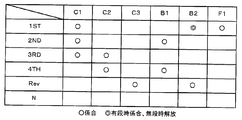
- FIG. 3 is an operation engagement table of the hybrid vehicle according to the first embodiment.
- the transmission 400 can change the gear ratio of the hybrid vehicle 1 in four steps (five steps including the reverse mode). Specifically, by engaging the first clutch C1, the second brake B2, and the one-way clutch F1, and releasing the second clutch C2, the third clutch C3, and the first brake B1, the gear ratio 1ST (that is, The state with the highest gear ratio is realized. By engaging the first clutch C1 and the first brake B1, and releasing the second clutch C2, the third clutch C3, the second brake B2, and the one-way clutch F1, the gear ratio 2ND (ie, the second gear) A high ratio) is realized.
- the gear ratio 3RD (ie, the third gear) A high ratio) is realized.
- the gear ratio 4TH (that is, the highest gear ratio). Low state) is realized.
- the reverse mode is realized by engaging the third clutch C3 and the second brake B2 and releasing the first clutch C1, the second clutch C2, the first brake B1, and the one-way clutch F1.
- the transmission 400 can realize a continuously variable transmission in addition to a stepped transmission.
- the second brake B2 when realizing the gear ratio 1ST is in a released state.
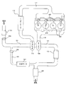
- FIG. 4 is a schematic configuration diagram showing the configuration of the internal combustion engine of the hybrid vehicle according to the first embodiment.
- the engine 200 according to the present embodiment is configured as a supercharged engine including a compressor 110 and a turbine 120.
- the compressor 110 compresses the air that has flowed in and supplies the compressed air downstream.
- Turbine 120 rotates using exhaust gas supplied from engine 200 via exhaust pipe 115 as power.
- the turbine 120 is connected to the compressor 110 via a shaft, and is configured to be able to rotate integrally with each other. That is, the turbine 120 and the compressor 110 constitute a turbocharger.
- the engine 200 is, for example, an in-line four-cylinder engine in which four cylinders 201 are arranged in series in a cylinder block. Although detailed illustration is omitted here, the engine 200 performs the reciprocating motion of the piston that occurs when the air-fuel mixture burns inside each cylinder 201 via the connecting rod. It can be converted into a rotational motion.
- An air flow meter 102 is provided in the intake pipe 101 on the inlet side (that is, upstream side of the compressor 110) of the compressor 110.
- the air flow meter 102 is configured to be able to detect the amount of air sucked from the outside.
- an intake throttle valve 103 is provided downstream of the air flow meter 102.
- the intake throttle valve 103 is an electronically controlled valve, for example, and is configured such that its opening / closing operation is controlled by a throttle valve motor (not shown). The amount of air flowing into the intake pipe 101 is adjusted by opening and closing the intake throttle valve 103.
- An intercooler 113 is provided in an intake pipe 111 on the outlet side of the compressor 110 (that is, downstream of the compressor 110) and on the intake side of the engine 200 (that is, upstream of the cylinder 201).
- the intercooler 113 is configured to be able to cool intake air and increase the supercharging efficiency of the air.
- an air-fuel mixture obtained by mixing air supplied through the intake pipe 111 and fuel supplied from the injector 210 is sucked.
- the air-fuel mixture introduced into the cylinder 201 from the intake side is ignited by a spark plug (not shown), compression ignition, or the like, and an explosion process is performed in the cylinder 201.
- the explosion process is performed, the burned air-fuel mixture (including a partially unburned air-fuel mixture) is discharged to an exhaust port (not shown) in the exhaust process following the explosion process.
- the exhaust discharged to the exhaust port is guided to the exhaust pipe 115.
- the exhaust pipe 121 on the outlet side of the turbine 120 (that is, the downstream side of the turbine 120) includes an EGR pipe 125, an EGR valve 126, and an EGR cooler 127 in addition to the start converter 123 and the aftertreatment device 124.
- a system is provided.
- the start converter 123 includes, for example, an oxidation catalyst, and purifies substances contained in the exhaust gas that has passed through the turbine 120.
- the post-processing device 124 is provided downstream of the start converter 123 in the exhaust pipe 122, and collects and reduces the particulate matter contained in the exhaust.
- the EGR pipe 125 is configured so that the exhaust downstream of the start converter 123 can be returned to the intake pipe 101 on the inlet side of the compressor 110.
- An EGR valve 126 is provided on the EGR pipe 125, and the amount of EGR gas can be adjusted.
- An EGR cooler 127 that cools the recirculated EGR gas is provided on the EGR pipe 125.
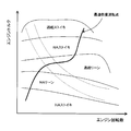
- FIG. 5 is a map showing operating points of the internal combustion engine of the hybrid vehicle according to the first embodiment.
- the engine 200 according to the present embodiment is configured as a supercharged engine as described above, supercharging combustion while supercharging is realized in addition to normal NA (Natural Aspiration) combustion. It is possible.
- NA Natural Aspiration
- stoichiometric combustion in which combustion is performed with an air-fuel mixture having a concentration close to the stoichiometric air-fuel ratio, and lean combustion in which combustion is performed with an air-fuel mixture thinner than the stoichiometric air-fuel ratio is possible.
- Each combustion state is selected from the relationship between the engine speed and the engine torque so as to realize an operation close to the optimum fuel consumption operating point indicated by a thick solid line in the figure.
- the operation at the optimum fuel efficiency operation point does not necessarily need to be realized, and the operation at the operation point deviating from the optimum fuel efficiency operation point may be realized according to the situation and specifications.
- FIG. 6 is a map showing the engine travel area and the motor travel area of the hybrid vehicle according to the first embodiment.
- hybrid vehicle 1 according to the present embodiment has an EV mode in which engine 200 is stopped and the vehicle travels only with the power of motor generators MG1 and MG2, and engine 200 is operated and engine 200, motor generators MG1 and MG2 are operated. It is possible to realize an HV mode that travels with power.
- the EV mode and the HV mode are determined according to the vehicle speed and the required driving force of the hybrid vehicle 1. Specifically, the EV mode is selected when the vehicle speed and the required driving force are relatively low, and the HV mode is selected when the vehicle speed and the required driving force are relatively high. Note that the map shown in FIG. 6 is a normal map. For example, when the engine 200 is warmed up or when the SOC is lowered, the motor travel area disappears (that is, the motor travel cannot be performed).
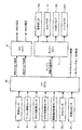
- FIG. 7 is a block diagram showing the configuration of the hybrid vehicle control device according to the first embodiment.
- control of each part of the hybrid vehicle 1 according to the present embodiment is executed by various electronic control units (ECU: Electronic Control Unit).
- ECU Electronic Control Unit
- the hybrid ECU 60 outputs a vehicle speed sensor 61 that outputs a signal corresponding to the vehicle speed of the vehicle 1, an accelerator opening sensor 62 that outputs a signal corresponding to the amount of depression of the accelerator pedal, and a signal corresponding to the rotational speed of the motor generator MG1.
- the output signals of the SOC sensor 66 that outputs a signal corresponding to the amount of charge of the engine, the air-fuel ratio sensor 67 that detects the air-fuel ratio of the engine 200, and the like are input.
- Hybrid ECU 60 calculates torque to be generated by motor generators MG1 and MG2, and outputs a command to MGECU 70 for the generated torque.
- Hybrid ECU 60 also determines the operating conditions of engine 200 and outputs a command to engine ECU 71 regarding the operating conditions of engine 200.
- the hybrid ECU 60 determines a gear ratio to be realized according to the vehicle speed, the required driving force, and the like of the hybrid vehicle 1, and the first clutch C1, the second clutch C2, the third clutch C3, and the first clutch in the transmission 400 are determined. The engagement state of the brake B1 and the second brake B2 is controlled.
- MGECU 70 calculates a voltage corresponding to the torque generated by motor generators MG1 and MG2 based on a command input from hybrid ECU 60, and outputs a voltage to each of motor generators MG1 and MG2.
- the engine ECU 71 performs various controls on the intake throttle valve 103, the spark plug 72, the EGR valve 126, the injector 210, and the like based on a command input from the hybrid ECU 60.
- FIG. 8 is a flowchart showing the operation of the control device for the hybrid vehicle according to the first embodiment.
- FIG. 9 is a shift diagram showing a shift prediction method in the hybrid vehicle control apparatus according to the first embodiment.
- shift lines corresponding to the vehicle speed and the accelerator opening are set in advance. Specifically, when the point determined according to the vehicle speed and the accelerator opening varies so as to cross the shift line, the shift according to the shift line is set. Therefore, if the variation in the vehicle speed and the accelerator opening can be predicted, the execution of the shift can be predicted.
- the calculated estimated time Tup is equal to or less than the predetermined value, it is predicted that the shift from the gear ratio 1ST to the gear ratio 2ND will be started soon.
- the calculated estimated time Tdwn is equal to or less than the predetermined value, it is predicted that the shift from the gear ratio 4TH to the gear ratio 3RD will be started soon.
- the shift is predicted on the assumption that either the accelerator opening or the vehicle speed does not change. However, even if both the accelerator opening and the vehicle speed change, the parameters described above are used. Can be used to predict the shift.
- step S101: NO when the above-described shift is not predicted (step S101: NO), the hybrid vehicle 1 performs normal control (step S106), and the series of processes ends.
- step S101: YES when a shift is predicted (step S101: YES), the air-fuel ratio of the engine 200 is detected by the air-fuel ratio sensor 67 (step S102).
- the starting point of the “predetermined period” of the present invention is the point in time when the shift is predicted, and until the shift is actually executed after the shift is predicted (that is, the shift operation of the transmission 400 is performed).
- the air-fuel ratio of the engine 200 is detected during the period until the engine is started.
- the air-fuel ratio may be determined in a period after a shift instruction is output to the transmission 400, for example, instead of the period after the shift is predicted.
- the HVECU 60 determines the required change amount of the engine speed of the engine 200 based on the current engine speed, the gear ratio after the shift, and the like (that is, the engine speed required to change during the shift). ) Is calculated (step S103).
- the HVECU 60 determines whether the air-fuel ratio is greater than or equal to the threshold value A and the required change amount is greater than the threshold value B (step S104).
- the threshold A is a threshold for determining that the air-fuel ratio of the engine 200 is high enough to cause inconvenience at the time of shifting, and torque reduction caused by the air-fuel ratio becoming leaner. It is set according to the decrease in the possible amount. Further, it is determined that the threshold B is so large that the required change amount of the engine 200 is large enough to execute the torque-down control or that the torque-down amount is not enough even if the torque-down control is executed at the present time. And is set in accordance with a predetermined torque reduction amount at the time of shifting.
- step S104 If it is determined that the air-fuel ratio is not greater than or equal to the threshold value A or the required change amount is not greater than the threshold value B (step S104: NO), it is determined that no inconvenience will occur without executing special control, and normal control is performed. Is executed (step S106). On the other hand, if it is determined that the air-fuel ratio is greater than or equal to threshold A and the required change amount is greater than threshold B (step S104: YES), the battery balance of motor generator MG is based on the air-fuel ratio and the required change amount. It is changed (step S105). Specifically, the battery balance of motor generator MG is controlled to the discharge side, so that motor generator MG can output a larger torque.
- the present embodiment when it is determined that the air-fuel ratio of the engine 200 after the shift prediction is equal to or greater than the threshold A and the required change amount is also greater than the threshold B (that is, there is an inconvenience during the shift).
- the battery balance of the motor generator MG is changed to the discharge side. Therefore, even when a sufficient torque reduction cannot be realized by the control of engine 200 itself, the torque reduction of engine 200 can be realized using the torque output from motor generator MG.
- how much the battery balance is changed to the discharge side may be determined according to the shortage of the torque reduction possible amount. For example, when the air-fuel ratio is larger (that is, when the air-fuel ratio is leaner), the engine is changed to a larger discharge side, and when the required change amount with respect to the engine speed is larger, the engine is changed to a larger discharge side. do it.
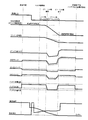
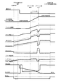
- FIG. 10 is a time chart showing a problem that occurs at the time of the upshift
- FIG. 11 is a time chart showing the control at the time of the upshift by the hybrid vehicle control device according to the first embodiment.
- FIG. 12 is a time chart showing a problem that occurs at the time of downshift
- FIG. 13 is a time chart showing control at the time of downshift by the hybrid vehicle control device according to the first embodiment.
- the torque sharing may be changed so as to decrease the output torque of the engine 200 and increase the output torque of the motor generator MG2 as shown in the figure.
- the torque sharing may be changed so as to increase the output torque of engine 200 and decrease the output torque of motor generator MG2, as shown in the figure.
- the torque sharing may be changed so as to decrease the output torque of the engine 200 and increase the output torque of the motor generator MG2 as shown in the figure.
- the torque sharing may be changed so as to increase the output torque of engine 200 and decrease the output torque of motor generator MG2, as shown in the figure.
- the amount of torque reduction can be increased by changing the battery balance by predicting a shift. Therefore, even when the engine 200 is performing lean combustion, sufficient torque-down control can be realized when shifting is performed. Therefore, inconveniences such as torque shock and deterioration of the durability of the friction material that can occur at the time of shifting can be suitably avoided.
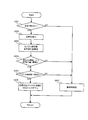
- FIG. 14 is a flowchart showing the operation of the hybrid vehicle control apparatus according to the second embodiment.
- the HVECU 60 predicts a shift by the transmission 400 (step S201). Note that since the shift prediction is the same as that in the first embodiment (see FIG. 9), detailed description thereof is omitted here.
- step S201: NO If no shift is predicted (step S201: NO), the hybrid vehicle 1 performs normal control (step S207), and the series of processes ends.
- step S201: YES when a shift is predicted (step S201: YES), the air-fuel ratio sensor 67 detects the air-fuel ratio of the engine 200 (step S202). Further, the HVECU 60 calculates a required change amount of the rotational speed of the engine 200 (that is, a rotational speed that is required to change during a shift) based on the current rotational speed of the engine 200, a gear ratio after the shift, and the like (ie Step S203).
- the HVECU 60 determines whether the air-fuel ratio is greater than or equal to the threshold value A and the required change amount is greater than the threshold value B (step S204). That is, as in the first embodiment, it is determined whether or not there is a situation where inconvenience at the time of shifting can occur.
- step S204: NO If it is determined that the air-fuel ratio is not equal to or greater than the threshold value A or the required change amount is not greater than the threshold value B (step S204: NO), it is determined that no inconvenience will occur without executing special control, and normal control is performed. Is executed (step S206). On the other hand, if it is determined that the air-fuel ratio is greater than or equal to the threshold A and the required change amount is greater than the threshold B (step S204: YES), it is determined whether or not there is a certain margin in the battery charge limit. (Step S205). Specifically, it is determined whether or not there is a margin in the battery charge limit to such an extent that it can cope with a change in battery balance accompanying air-fuel ratio change control, which will be described later.
- step S205 If it is determined that the battery charge limit is not sufficient (step S205: NO), the subsequent processing is not performed and the normal control is executed (step S207). On the other hand, if it is determined that the battery charge limit is sufficient (step S205: YES), the air-fuel ratio is changed from lean to stoichiometric (that is, rich), and torque-down control of motor generator MG2 is performed. It is executed (step S206).
- how much the air-fuel ratio is changed to the rich side may be determined according to the shortage of the torque reduction possible amount. For example, when the air-fuel ratio is larger (that is, when the air-fuel ratio is leaner), the engine is changed to a larger rich side. When the required change amount with respect to the engine speed is larger, the engine is changed to a larger rich side. do it.
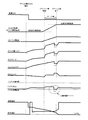
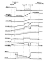
- FIG. 15 is a time chart showing the control at the time of upshifting by the hybrid vehicle control device according to the second embodiment.
- FIG. 16 is a time chart showing control during downshifting by the hybrid vehicle control device according to the second embodiment.
- the air-fuel ratio is changed to the rich side when the upshift is predicted.
- the torque fluctuation in the engine 200 decreases, and the amount of torque reduction possible increases. Therefore, at the time of shifting, the torque reduction control can be suitably executed by the control of the engine 200 itself (for example, ignition timing retardation control, etc.). Note that after the shift is completed, control is performed again to return the air-fuel ratio to the state before the change (that is, the lean side).
- the output torque of the engine 200 increases as shown in the figure, so that the total output torque is adjusted by decreasing the output torque of the motor generator MG2.
- the total output torque is adjusted by increasing the output torque of motor generator MG2 in order to decrease the output torque of engine 200 as shown in the figure.
- the air-fuel ratio is changed to the rich side when the downshift is predicted.
- the torque fluctuation in the engine 200 decreases, and the amount of torque reduction possible increases. Therefore, at the time of shifting, the torque reduction control can be suitably executed by the control of the engine 200 itself (for example, ignition timing retardation control, etc.). Note that after the shift is completed, control is performed again to return the air-fuel ratio to the state before the change (that is, the lean side).
- the total output torque is adjusted by decreasing the output torque of the motor generator MG2.
- the total output torque is adjusted by increasing the output torque of motor generator MG2 in order to decrease the output torque of engine 200.
- the amount of torque reduction possible by the control of the engine itself can be increased by changing the air-fuel ratio by predicting a shift. Therefore, even when the engine 200 at the time of the shift prediction is lean burning, sufficient torque down control can be realized when the shift is executed. Therefore, inconveniences such as torque shock and deterioration of the durability of the friction material that can occur at the time of shifting can be suitably avoided.
- FIG. 17 is a flowchart showing the operation of the hybrid vehicle control apparatus according to the third embodiment.
- the HVECU 60 predicts a shift by the transmission 400 (step S301). Note that since the shift prediction is the same as that in the first embodiment (see FIG. 9), detailed description thereof is omitted here.
- step S301: NO If no shift is predicted (step S301: NO), the hybrid vehicle 1 performs normal control (step S309), and the series of processes ends.
- step S301: YES when a shift is predicted (step S301: YES), the air-fuel ratio of the engine 200 is detected by the air-fuel ratio sensor 67 (step S302). Further, the HVECU 60 calculates a required change amount of the rotational speed of the engine 200 (that is, a rotational speed that is required to change during a shift) based on the current rotational speed of the engine 200, a gear ratio after the shift, and the like (ie Step S303).
- the HVECU 60 determines whether the air-fuel ratio is greater than or equal to the threshold value A and the required change amount is greater than the threshold value B (step S304). That is, as in the first and second embodiments, it is determined whether or not there is a situation where inconvenience at the time of shifting can occur.
- step S304: NO If it is determined that the air-fuel ratio is not equal to or greater than the threshold value A or the required change amount is not greater than the threshold value B (step S304: NO), it is determined that no inconvenience will occur even if special control is not performed. Is executed (step S309). On the other hand, if it is determined that the air-fuel ratio is greater than or equal to the threshold A and the required change amount is greater than the threshold B (step S304: YES), it is determined whether or not there is a certain margin in the battery discharge limit. (Step S305). Specifically, as described in the first embodiment, when the battery balance is controlled to the discharge side, it is determined whether or not the battery discharge limitation is a problem.
- the battery discharge limit value is applied. Therefore, the battery balance cannot be sufficiently changed to the discharge side. Therefore, in such a case, it is determined that there is no margin in the battery discharge limit.
- step S305 If it is determined that the battery discharge limit is sufficient (step S305: YES), the battery balance of the motor generator MG is changed based on the air-fuel ratio and the required change amount (step S306). That is, similarly to the first embodiment, the battery balance of the motor generator MG is controlled to the discharge side, so that the motor generator MG can output a larger torque. Therefore, it is possible to suitably execute torque-down control at the time of shifting.
- step S306 if it is determined that there is no margin in the battery discharge limit (step S306: NO), it is determined whether there is a certain margin in the battery charge limitation (step S307). That is, it is determined that an increase in the torque reduction possible amount due to the change in the battery balance cannot be expected, and it is determined whether or not the air-fuel ratio change control described in the second embodiment can be executed.
- step S307 If it is determined that the battery charge limit is sufficient (step S307: YES), the air-fuel ratio is changed from lean to stoichiometric (ie, rich), and torque-down control of motor generator MG2 is executed. (Step S206). That is, the amount of torque reduction that has been reduced due to lean combustion increases by changing to stoichiometric combustion, and a sufficient amount of torque reduction is ensured. Further, the output torque of motor generator MG2 is controlled to decrease, and the influence of the increase in output of engine 200 due to the change of the air-fuel ratio to the rich side is reduced.
- step S307 If it is determined that there is no allowance for the battery charge limit (step S307: NO), it is determined that neither the change of the battery balance nor the change of the air-fuel ratio can be executed, and the normal control is executed (step S309). ).
- the hybrid vehicle control device of the third embodiment when the shift is predicted, either the battery balance change control or the air-fuel ratio change control is appropriately selected according to the conditions. And executed. Therefore, even in a situation where either one of the battery balance change control and the air-fuel ratio change control cannot be executed, the torque reduction possible amount can be reliably increased by the other control. Therefore, inconveniences such as torque shock and deterioration of the durability of the friction material that can occur at the time of shifting can be avoided more suitably.
- the present invention is not limited to the above-described embodiment, and can be appropriately changed without departing from the gist or concept of the invention that can be read from the claims and the entire specification, and control of a hybrid vehicle involving such a change.
- the apparatus is also included in the technical scope of the present invention.
Landscapes
- Engineering & Computer Science (AREA)
- Mechanical Engineering (AREA)
- Chemical & Material Sciences (AREA)
- Combustion & Propulsion (AREA)
- Transportation (AREA)
- General Engineering & Computer Science (AREA)
- Automation & Control Theory (AREA)
- Power Engineering (AREA)
- Electric Propulsion And Braking For Vehicles (AREA)
- Hybrid Electric Vehicles (AREA)
- Control Of Vehicle Engines Or Engines For Specific Uses (AREA)
- Electrical Control Of Air Or Fuel Supplied To Internal-Combustion Engine (AREA)
Abstract
Description
本発明のハイブリッド車両の制御装置は、空燃比を変更可能な内燃機関及び電動機を含む動力源と、前記内燃機関の回転数を変更可能な変速手段とを備えたハイブリッド車両を制御する装置であって、実際に前記変速手段による変速が実行されるまでの所定期間において、前記内燃機関の空燃比を判定する空燃比判定手段と、前記所定期間における前記内燃機関の空燃比がリーンである場合に、前記内燃機関のトルクダウン可能量が大きくなるように、前記内燃機関及び前記電動機の少なくとも一方を制御する制御手段とを備える。
本発明のハイブリッド車両の制御装置の一態様では、前記制御手段は、前記内燃機関及び前記電動機の出力配分について、前記内燃機関の空燃比がリーンである場合と比べて前記電動機の出力配分が大きくなるように制御する。
上述した電動機の出力配分を大きくする態様では、前記制御手段は、前記内燃機関の空燃比がリーン側であるほど、前記電動機の出力配分が大きくなるように制御してもよい。
或いは電動機の出力配分を大きくする態様では、前記制御手段は、前記変速を実行する際の前記内燃機関に対する回転数の要求変化量が大きいほど、前記電動機の出力配分が大きくなるように制御してもよい。
本発明のハイブリッド車両の制御装置の他の態様では、前記制御手段は、前記内燃機関の空燃比をリッチ側に変更し、且つ前記電動機の出力が低下するように制御する。
上述した空燃比をリッチ側に制御する態様では、前記制御手段は、前記変速を実行する際の前記内燃機関に対する回転数の要求変化量が大きいほど、前記内燃機関の空燃比がリッチ側となるように制御してもよい。
第1実施形態に係るハイブリッド車両の制御装置について、図1から図13を参照して説明する。
先ず、図1を参照しながら、本実施形態に係るハイブリッド車両1の全体構成(特に、駆動機構の構成)について説明する。ここに図1は、第1実施形態に係るハイブリッド車両の全体構成を示すスケルトン図である。
次に、図2及び3を参照しながら、本実施形態に係る変速機400により実現可能なギヤ比について具体的に説明する。ここに図2は、第1実施形態に係るハイブリッド車両の速度線図である。また図3は、第1実施形態に係るハイブリッド車両の作動係合表である。
次に、本実施形態に係るハイブリッド車両1のエンジン200まわりの構成について、図4を参照して説明する。ここに図4は、第1実施形態に係るハイブリッド車両の内燃機関の構成を示す概略構成図である。
次に、図5を参照しながら、上述した本実施形態に係るエンジン200が実現し得る燃焼モードについて説明する。ここに図5は、第1実施形態に係るハイブリッド車両の内燃機関の運転点を示すマップである。
次に、図6を参照しながら、ハイブリッド車両1において実現される走行モードについて説明する。ここに図6は、第1実施形態に係るハイブリッド車両のエンジン走行領域及びモータ走行領域を示すマップである。
次に、図7を参照しながら、実施形態に係るハイブリッド車両の制御装置の構成について説明する。ここに図7は、第1実施形態に係るハイブリッド車両の制御装置の構成を示すブロック図である。
次に、図8を参照しながら、本実施形態に係るハイブリッド車両の制御装置の動作について説明する。ここに図8は、第1実施形態に係るハイブリッド車両の制御装置の動作を示すフローチャートである。
次に、図10から図13を参照しながら、変速時に発生し得る不都合及びそれを解消するための本実施形態に係る制御の具体例について説明する。ここに図10は、アップ変速時に発生する課題を示すタイムチャートであり、図11は、第1実施形態に係るハイブリッド車両の制御装置によるアップ変速時の制御を示すタイムチャートである。また図12は、ダウン変速時に発生する課題を示すタイムチャートであり、図13は、第1実施形態に係るハイブリッド車両の制御装置によるダウン変速時の制御を示すタイムチャートである。
続いて、第2実施形態に係るハイブリッド車両の制御装置について、図14から図16を参照して説明する。なお、第2実施形態は、上述した第1実施形態と比較して一部の動作が異なるのみであり、他の動作や装置構成については概ね同様である。このため、以下では第1実施形態と異なる部分について詳細に説明し、重複する部分については適宜説明を省略するものとする。
先ず、図14を参照しながら、第2実施形態に係るハイブリッド車両の制御装置の動作について説明する。ここに図14は、第2実施形態に係るハイブリッド車両の制御装置の動作を示すフローチャートである。
次に、図15及び図16を参照しながら、第2実施形態に係る変速時の制御の具体例について説明する。ここに図15は、第2実施形態に係るハイブリッド車両の制御装置によるアップ変速時の制御を示すタイムチャートである。また図16は、第2実施形態に係るハイブリッド車両の制御装置によるダウン変速時の制御を示すタイムチャートである。
続いて、第3実施形態に係るハイブリッド車両の制御装置について、図17を参照して説明する。なお、第3実施形態は、上述した第1及び第2実施形態と比較して一部の動作が異なるのみであり、他の動作や装置構成については概ね同様である。このため、以下では第1及び第2実施形態と異なる部分について詳細に説明し、重複する部分については適宜説明を省略するものとする。
先ず、図17を参照しながら、第3実施形態に係るハイブリッド車両の制御装置の動作について説明する。ここに図17は、第3実施形態に係るハイブリッド車両の制御装置の動作を示すフローチャートである。
6 駆動軸
60 HVECU
61 車速センサ
62 アクセル開度センサ
63 MG1回転数センサ
64 MG2回転数センサ
65 駆動軸回転数センサ
66 SOCセンサ
67 空燃比センサ
70 MGECU
71 エンジンECU
72 点火プラグ
101,111 吸気管
102 エアフローメータ
103 吸気絞り弁
110 コンプレッサ
113 インタークーラ
120 タービン
115,121 排気管
123 スタートコンバータ
124 後処理装置
125 EGR管
126 EGRバルブ
127 EGRクーラ
200 エンジン
201 シリンダ
210 インジェクタ
300 遊星歯車機構
400 変速機
MG1,MG2 モータジェネレータ
S0,S1,S2 サンギヤ
CA0,CA1,CA2 キャリア
R0,R1,R2 リングギヤ
C1,C2,C3 クラッチ
F1 一方向クラッチ
B1,B2 ブレーキ
Claims (6)
- 空燃比を変更可能な内燃機関及び電動機を含む動力源と、
前記内燃機関の回転数を変更可能な変速手段と
を備えたハイブリッド車両を制御する装置であって、
実際に前記変速手段による変速が実行されるまでの所定期間において、前記内燃機関の空燃比を判定する空燃比判定手段と、
前記所定期間における前記内燃機関の空燃比がリーンである場合に、前記内燃機関のトルクダウン可能量が大きくなるように、前記内燃機関及び前記電動機の少なくとも一方を制御する制御手段と
を備えることを特徴とするハイブリッド車両の制御装置。 - 前記制御手段は、前記内燃機関及び前記電動機の出力配分について、前記内燃機関の空燃比がリーンである場合と比べて前記電動機の出力配分が大きくなるように制御することを特徴とする請求項1に記載のハイブリッド車両の制御装置。
- 前記制御手段は、前記内燃機関の空燃比がリーン側であるほど、前記電動機の出力配分が大きくなるように制御することを特徴とする請求項2に記載のハイブリッド車両の制御装置。
- 前記制御手段は、前記変速を実行する際の前記内燃機関に対する回転数の要求変化量が大きいほど、前記電動機の出力配分が大きくなるように制御することを特徴とする請求項2又は3に記載のハイブリッド車両の制御装置。
- 前記制御手段は、前記内燃機関の空燃比をリッチ側に変更し、且つ前記電動機の出力が低下するように制御することを特徴とする請求項1に記載のハイブリッド車両の制御装置。
- 前記制御手段は、前記変速を実行する際の前記内燃機関に対する回転数の要求変化量が大きいほど、前記内燃機関の空燃比がリッチ側となるように制御することを特徴とする請求項5に記載のハイブリッド車両の制御装置。
Priority Applications (3)
| Application Number | Priority Date | Filing Date | Title |
|---|---|---|---|
| KR1020167018404A KR101728433B1 (ko) | 2014-02-26 | 2014-11-27 | 하이브리드 차량의 제어 장치 |
| US15/121,127 US9975540B2 (en) | 2014-02-26 | 2014-11-27 | Control apparatus for hybrid vehicle |
| CN201480075934.XA CN106029461B (zh) | 2014-02-26 | 2014-11-27 | 混合动力车辆的控制装置 |
Applications Claiming Priority (2)
| Application Number | Priority Date | Filing Date | Title |
|---|---|---|---|
| JP2014035275A JP5742984B1 (ja) | 2014-02-26 | 2014-02-26 | ハイブリッド車両の制御装置 |
| JP2014-035275 | 2014-02-26 |
Publications (1)
| Publication Number | Publication Date |
|---|---|
| WO2015129114A1 true WO2015129114A1 (ja) | 2015-09-03 |
Family
ID=53537048
Family Applications (1)
| Application Number | Title | Priority Date | Filing Date |
|---|---|---|---|
| PCT/JP2014/081420 Ceased WO2015129114A1 (ja) | 2014-02-26 | 2014-11-27 | ハイブリッド車両の制御装置 |
Country Status (5)
| Country | Link |
|---|---|
| US (1) | US9975540B2 (ja) |
| JP (1) | JP5742984B1 (ja) |
| KR (1) | KR101728433B1 (ja) |
| CN (1) | CN106029461B (ja) |
| WO (1) | WO2015129114A1 (ja) |
Cited By (1)
| Publication number | Priority date | Publication date | Assignee | Title |
|---|---|---|---|---|
| JP2017053228A (ja) * | 2015-09-07 | 2017-03-16 | トヨタ自動車株式会社 | 車両の制御装置 |
Families Citing this family (6)
| Publication number | Priority date | Publication date | Assignee | Title |
|---|---|---|---|---|
| JP6287802B2 (ja) * | 2014-12-12 | 2018-03-07 | トヨタ自動車株式会社 | 内燃機関の制御装置 |
| DE102016207480A1 (de) * | 2016-05-02 | 2017-11-02 | Zf Friedrichshafen Ag | Getriebe für ein Kraftfahrzeug |
| JP7027937B2 (ja) * | 2018-02-16 | 2022-03-02 | トヨタ自動車株式会社 | ハイブリッド車両の制御装置 |
| GB201817229D0 (en) * | 2018-10-23 | 2018-12-05 | Rolls Royce Plc | Epicyclic gearbox |
| JP7183928B2 (ja) * | 2019-04-10 | 2022-12-06 | トヨタ自動車株式会社 | 車両 |
| JP7287233B2 (ja) * | 2019-10-03 | 2023-06-06 | トヨタ自動車株式会社 | ハイブリッド車両の制御装置 |
Citations (6)
| Publication number | Priority date | Publication date | Assignee | Title |
|---|---|---|---|---|
| JPH06317194A (ja) * | 1993-05-10 | 1994-11-15 | Mazda Motor Corp | 自動変速機の制御装置 |
| JPH07166901A (ja) * | 1993-12-14 | 1995-06-27 | Toyota Motor Corp | 自動変速機付内燃機関の制御装置 |
| JP2007186197A (ja) * | 2007-02-01 | 2007-07-26 | Toyota Motor Corp | ハイブリッド車両の制御装置 |
| JP2008196502A (ja) * | 2008-05-19 | 2008-08-28 | Toyota Motor Corp | 車両の制御装置 |
| JP2009107414A (ja) * | 2007-10-26 | 2009-05-21 | Toyota Motor Corp | 車両の駆動力制御装置 |
| JP2009144575A (ja) * | 2007-12-12 | 2009-07-02 | Toyota Motor Corp | 車両用動力伝達装置の制御装置 |
Family Cites Families (6)
| Publication number | Priority date | Publication date | Assignee | Title |
|---|---|---|---|---|
| US6000378A (en) * | 1991-02-25 | 1999-12-14 | Hitachi, Ltd. | Change gear control device using acceleration and gear ratio as parameters for automatic transmission in a motor vehicle and the method therefor |
| JP3166595B2 (ja) | 1995-12-28 | 2001-05-14 | トヨタ自動車株式会社 | 自動変速機付内燃機関の制御装置 |
| JP3661071B2 (ja) * | 1996-04-10 | 2005-06-15 | 本田技研工業株式会社 | ハイブリッド車両の制御装置 |
| JP3915809B2 (ja) * | 2004-09-21 | 2007-05-16 | トヨタ自動車株式会社 | リーンリミットを低電力消費にて達成するハイブリッド車 |
| JP2007168495A (ja) * | 2005-12-19 | 2007-07-05 | Toyota Motor Corp | 動力出力装置及びその制御方法並びに車両 |
| JP4197025B2 (ja) * | 2006-09-15 | 2008-12-17 | トヨタ自動車株式会社 | ハイブリッド車両 |
-
2014
- 2014-02-26 JP JP2014035275A patent/JP5742984B1/ja not_active Expired - Fee Related
- 2014-11-27 CN CN201480075934.XA patent/CN106029461B/zh not_active Expired - Fee Related
- 2014-11-27 KR KR1020167018404A patent/KR101728433B1/ko not_active Expired - Fee Related
- 2014-11-27 WO PCT/JP2014/081420 patent/WO2015129114A1/ja not_active Ceased
- 2014-11-27 US US15/121,127 patent/US9975540B2/en active Active
Patent Citations (6)
| Publication number | Priority date | Publication date | Assignee | Title |
|---|---|---|---|---|
| JPH06317194A (ja) * | 1993-05-10 | 1994-11-15 | Mazda Motor Corp | 自動変速機の制御装置 |
| JPH07166901A (ja) * | 1993-12-14 | 1995-06-27 | Toyota Motor Corp | 自動変速機付内燃機関の制御装置 |
| JP2007186197A (ja) * | 2007-02-01 | 2007-07-26 | Toyota Motor Corp | ハイブリッド車両の制御装置 |
| JP2009107414A (ja) * | 2007-10-26 | 2009-05-21 | Toyota Motor Corp | 車両の駆動力制御装置 |
| JP2009144575A (ja) * | 2007-12-12 | 2009-07-02 | Toyota Motor Corp | 車両用動力伝達装置の制御装置 |
| JP2008196502A (ja) * | 2008-05-19 | 2008-08-28 | Toyota Motor Corp | 車両の制御装置 |
Cited By (1)
| Publication number | Priority date | Publication date | Assignee | Title |
|---|---|---|---|---|
| JP2017053228A (ja) * | 2015-09-07 | 2017-03-16 | トヨタ自動車株式会社 | 車両の制御装置 |
Also Published As
| Publication number | Publication date |
|---|---|
| US9975540B2 (en) | 2018-05-22 |
| JP5742984B1 (ja) | 2015-07-01 |
| CN106029461A (zh) | 2016-10-12 |
| KR101728433B1 (ko) | 2017-04-19 |
| US20170021817A1 (en) | 2017-01-26 |
| JP2015160456A (ja) | 2015-09-07 |
| CN106029461B (zh) | 2018-06-22 |
| KR20160096681A (ko) | 2016-08-16 |
Similar Documents
| Publication | Publication Date | Title |
|---|---|---|
| US11541872B2 (en) | Vehicle and control method thereof | |
| JP5742984B1 (ja) | ハイブリッド車両の制御装置 | |
| JP6241438B2 (ja) | ハイブリッド車両の制御装置 | |
| JP4615037B2 (ja) | ハイブリッド自動車およびその制御方法 | |
| US11628819B2 (en) | Hybrid vehicle and control method thereof | |
| JP6137310B2 (ja) | ハイブリッド車両の制御装置 | |
| US11371452B2 (en) | Vehicle and control method therefor | |
| US11623634B2 (en) | Hybrid vehicle and control method therefor | |
| JP2012219622A (ja) | 内燃機関の制御装置 | |
| CN105317576A (zh) | 用于内燃机的控制设备 | |
| JP2009041421A (ja) | 内燃機関の噴射量学習装置 | |
| JP2016037105A (ja) | ハイブリッド車両の内燃機関始動制御装置 | |
| CN105636846B (zh) | 混合动力车辆的控制装置 | |
| US11274619B2 (en) | Vehicle and control method therefor | |
| JP5395041B2 (ja) | 車両、内燃機関の異常判定方法および内燃機関の異常判定装置 | |
| JP2013112101A (ja) | ハイブリッド車 | |
| CN112009482A (zh) | 混合动力车辆 | |
| JP2015223907A (ja) | ハイブリッド車両の制御装置 | |
| JP2014181643A (ja) | 内燃機関の制御装置 | |
| JP6020281B2 (ja) | 車両 | |
| JP4311414B2 (ja) | 車両およびその制御方法 | |
| JP2021161936A (ja) | 車両の制御装置 | |
| JP2015120422A (ja) | ハイブリッド車両の制御装置 |
Legal Events
| Date | Code | Title | Description |
|---|---|---|---|
| 121 | Ep: the epo has been informed by wipo that ep was designated in this application |
Ref document number: 14884034 Country of ref document: EP Kind code of ref document: A1 |
|
| ENP | Entry into the national phase |
Ref document number: 20167018404 Country of ref document: KR Kind code of ref document: A |
|
| WWE | Wipo information: entry into national phase |
Ref document number: 15121127 Country of ref document: US |
|
| NENP | Non-entry into the national phase |
Ref country code: DE |
|
| 122 | Ep: pct application non-entry in european phase |
Ref document number: 14884034 Country of ref document: EP Kind code of ref document: A1 |