WO2015129046A1 - 後処理装置の管理装置、作業車両、管理システムおよび後処理装置の管理方法 - Google Patents
後処理装置の管理装置、作業車両、管理システムおよび後処理装置の管理方法 Download PDFInfo
- Publication number
- WO2015129046A1 WO2015129046A1 PCT/JP2014/055163 JP2014055163W WO2015129046A1 WO 2015129046 A1 WO2015129046 A1 WO 2015129046A1 JP 2014055163 W JP2014055163 W JP 2014055163W WO 2015129046 A1 WO2015129046 A1 WO 2015129046A1
- Authority
- WO
- WIPO (PCT)
- Prior art keywords
- reproduction
- occurrence status
- post
- processing
- division
- Prior art date
- Legal status (The legal status is an assumption and is not a legal conclusion. Google has not performed a legal analysis and makes no representation as to the accuracy of the status listed.)
- Ceased
Links
Images



Classifications
-
- G—PHYSICS
- G07—CHECKING-DEVICES
- G07C—TIME OR ATTENDANCE REGISTERS; REGISTERING OR INDICATING THE WORKING OF MACHINES; GENERATING RANDOM NUMBERS; VOTING OR LOTTERY APPARATUS; ARRANGEMENTS, SYSTEMS OR APPARATUS FOR CHECKING NOT PROVIDED FOR ELSEWHERE
- G07C5/00—Registering or indicating the working of vehicles
- G07C5/006—Indicating maintenance
-
- G—PHYSICS
- G06—COMPUTING OR CALCULATING; COUNTING
- G06Q—INFORMATION AND COMMUNICATION TECHNOLOGY [ICT] SPECIALLY ADAPTED FOR ADMINISTRATIVE, COMMERCIAL, FINANCIAL, MANAGERIAL OR SUPERVISORY PURPOSES; SYSTEMS OR METHODS SPECIALLY ADAPTED FOR ADMINISTRATIVE, COMMERCIAL, FINANCIAL, MANAGERIAL OR SUPERVISORY PURPOSES, NOT OTHERWISE PROVIDED FOR
- G06Q50/00—Information and communication technology [ICT] specially adapted for implementation of business processes of specific business sectors, e.g. utilities or tourism
- G06Q50/10—Services
-
- E—FIXED CONSTRUCTIONS
- E02—HYDRAULIC ENGINEERING; FOUNDATIONS; SOIL SHIFTING
- E02F—DREDGING; SOIL-SHIFTING
- E02F9/00—Component parts of dredgers or soil-shifting machines, not restricted to one of the kinds covered by groups E02F3/00 - E02F7/00
- E02F9/20—Drives; Control devices
- E02F9/2025—Particular purposes of control systems not otherwise provided for
- E02F9/2054—Fleet management
-
- E—FIXED CONSTRUCTIONS
- E02—HYDRAULIC ENGINEERING; FOUNDATIONS; SOIL SHIFTING
- E02F—DREDGING; SOIL-SHIFTING
- E02F9/00—Component parts of dredgers or soil-shifting machines, not restricted to one of the kinds covered by groups E02F3/00 - E02F7/00
- E02F9/20—Drives; Control devices
- E02F9/2058—Electric or electro-mechanical or mechanical control devices of vehicle sub-units
- E02F9/2062—Control of propulsion units
- E02F9/2066—Control of propulsion units of the type combustion engines
-
- E—FIXED CONSTRUCTIONS
- E02—HYDRAULIC ENGINEERING; FOUNDATIONS; SOIL SHIFTING
- E02F—DREDGING; SOIL-SHIFTING
- E02F9/00—Component parts of dredgers or soil-shifting machines, not restricted to one of the kinds covered by groups E02F3/00 - E02F7/00
- E02F9/26—Indicating devices
- E02F9/267—Diagnosing or detecting failure of vehicles
-
- F—MECHANICAL ENGINEERING; LIGHTING; HEATING; WEAPONS; BLASTING
- F01—MACHINES OR ENGINES IN GENERAL; ENGINE PLANTS IN GENERAL; STEAM ENGINES
- F01N—GAS-FLOW SILENCERS OR EXHAUST APPARATUS FOR MACHINES OR ENGINES IN GENERAL; GAS-FLOW SILENCERS OR EXHAUST APPARATUS FOR INTERNAL-COMBUSTION ENGINES
- F01N3/00—Exhaust or silencing apparatus having means for purifying, rendering innocuous, or otherwise treating exhaust
- F01N3/08—Exhaust or silencing apparatus having means for purifying, rendering innocuous, or otherwise treating exhaust for rendering innocuous
-
- F—MECHANICAL ENGINEERING; LIGHTING; HEATING; WEAPONS; BLASTING
- F01—MACHINES OR ENGINES IN GENERAL; ENGINE PLANTS IN GENERAL; STEAM ENGINES
- F01N—GAS-FLOW SILENCERS OR EXHAUST APPARATUS FOR MACHINES OR ENGINES IN GENERAL; GAS-FLOW SILENCERS OR EXHAUST APPARATUS FOR INTERNAL-COMBUSTION ENGINES
- F01N9/00—Electrical control of exhaust gas treating apparatus
- F01N9/002—Electrical control of exhaust gas treating apparatus of filter regeneration
-
- F—MECHANICAL ENGINEERING; LIGHTING; HEATING; WEAPONS; BLASTING
- F01—MACHINES OR ENGINES IN GENERAL; ENGINE PLANTS IN GENERAL; STEAM ENGINES
- F01N—GAS-FLOW SILENCERS OR EXHAUST APPARATUS FOR MACHINES OR ENGINES IN GENERAL; GAS-FLOW SILENCERS OR EXHAUST APPARATUS FOR INTERNAL-COMBUSTION ENGINES
- F01N9/00—Electrical control of exhaust gas treating apparatus
- F01N9/007—Storing data relevant to operation of exhaust systems for later retrieval and analysis, e.g. to research exhaust system malfunctions
-
- Y—GENERAL TAGGING OF NEW TECHNOLOGICAL DEVELOPMENTS; GENERAL TAGGING OF CROSS-SECTIONAL TECHNOLOGIES SPANNING OVER SEVERAL SECTIONS OF THE IPC; TECHNICAL SUBJECTS COVERED BY FORMER USPC CROSS-REFERENCE ART COLLECTIONS [XRACs] AND DIGESTS
- Y02—TECHNOLOGIES OR APPLICATIONS FOR MITIGATION OR ADAPTATION AGAINST CLIMATE CHANGE
- Y02T—CLIMATE CHANGE MITIGATION TECHNOLOGIES RELATED TO TRANSPORTATION
- Y02T10/00—Road transport of goods or passengers
- Y02T10/10—Internal combustion engine [ICE] based vehicles
- Y02T10/40—Engine management systems
Definitions
- the present invention relates to a management device for a post-processing device, a work vehicle, a management system, and a management method for the post-processing device.
- the management server communicates with the management server using a wireless LAN (Local Area Network) or the like, and manages information such as work vehicle position information, operation status, and failure history (see, for example, Patent Document 1).
- a wireless LAN Local Area Network
- the work vehicle uses an internal combustion engine such as a diesel engine as a drive source.
- particulate matter such as a diesel engine
- DPF Diesel Particulate Filter
- a collecting post-processing device is provided. In the post-processing device, clogging of the filter occurs when the collected amount of collected PM increases. Therefore, regeneration processing for removing the clogging of the filter by burning the collected PM is performed.
- Patent Document 2 In such a post-processing device, there is known a device for transmitting the number of manual regeneration operations from a construction machine controller to a construction machine rental company server and calculating the maintenance cost (see Patent Document 2). ).
- PM is incinerated and removed by automatic regeneration, but a warning for prompting manual regeneration is displayed on the display device when it is not successfully removed.
- the controller When the operator views the warning display and operates the regeneration switch, manual regeneration is performed. Then, the controller counts the number of regeneration operations based on the operation signal from the regeneration switch, and transmits the number of regeneration operations to the server of the management company via the wireless communication device.
- An object of the present invention is to provide a management device for a post-processing device, a work vehicle, a management system, and a management method for the post-processing device that can correctly acquire the data of the playback processing status even when the work vehicle is stopped by a key-off operation during the playback processing. Is to provide.
- the present invention is a management device that manages a post-processing device that processes residual substances in exhaust gas, and a regeneration occurrence status output unit that outputs regeneration occurrence status data indicating the occurrence status of regeneration processing of the post-processing device;
- a reproduction division detection unit that detects that the reproduction process has been divided by performing a key-off operation during execution of the reproduction process, and the reproduction occurrence status output unit is detected by the reproduction division detection unit
- Reproduction occurrence status data that can be analyzed that a reproduction process before division and a reproduction process resumed after division are a series of reproduction processes is output.
- the reproduction occurrence status output unit determines that the reproduction process is divided by the reproduction division detection unit, the reproduction process is divided into the reproduction occurrence status data. It is preferable to output by adding the division information shown.
- the management apparatus of the post-processing apparatus includes a storage unit, and the reproduction occurrence status output unit stores the reproduction occurrence status data in the storage unit when a key-off operation is performed during the execution of the reproduction process. And the reproduction division detection unit determines whether or not the reproduction process has been divided based on the reproduction occurrence status data stored in the storage means after the key-on operation, and the reproduction occurrence status output unit When it is determined that the reproduction process has been divided by the reproduction division detection unit, it is preferable to add division information indicating that the reproduction process has been divided to the reproduction occurrence status data stored in the storage means and output the result.
- a storage means for storing a reproduction process execution flag indicating that the reproduction process is in progress and the reproduction occurrence status data, and the necessity of the reproduction process of the post-processing apparatus are determined.
- a reproduction necessity determination unit wherein the reproduction necessity determination unit sets the reproduction process execution flag to ON when it is determined that the reproduction process is necessary, and determines that the reproduction process is divided by the reproduction division detection unit. If the reproduction process execution flag is maintained, the reproduction process execution flag is set to off when it is determined that the reproduction process has changed from a necessary state to an unnecessary state.
- the reproduction occurrence status data from when the reproduction processing execution flag is set to on until it is set to off is output as one data.
- a work vehicle includes a management device for the post-processing device.
- the management system of the present invention includes a management device of the post-processing device and a management server that receives and acquires the reproduction occurrence status data output from the management device.
- the present invention relates to a management method for a post-processing device, wherein a playback occurrence status output step for outputting playback occurrence status data indicating a status of occurrence of the playback processing of the post-processing device, and a key-off operation during the execution of the playback processing.
- a reproduction division detection step that is performed and detects that the reproduction process has been divided, and the reproduction occurrence status output step restarts after the division and the reproduction process before the division detected in the reproduction division detection step It is characterized by outputting reproduction occurrence status data that can be analyzed that the reproduced processing is a series of reproduction processing.
- the reproduction division detection unit since the reproduction division detection unit is provided, it is possible to detect that the reproduction process is divided by performing a key-off operation during the reproduction process and notify the reproduction occurrence status output unit. For this reason, the reproduction occurrence status output unit can output to the management server or the like reproduction occurrence status data that can be analyzed that the reproduction processing before and after the division is a series of reproduction processing. Therefore, even when the regeneration process is divided, it is possible to correctly manage the regeneration process status of the post-processing apparatus that performs processes such as collection and reduction of residual substances such as PM and NOx in the exhaust gas.
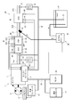
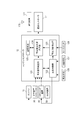
- the schematic diagram which shows the management system of the post-processing apparatus concerning 1st Embodiment of this invention The schematic diagram which shows the structure of the post-processing apparatus and management apparatus of 1st Embodiment.
- the flowchart which shows the management method of the post-processing apparatus of 1st Embodiment.
- FIG. 1 is a schematic diagram showing a schematic configuration of a management system 100 for a post-processing apparatus according to the present embodiment.
- the management system 100 includes a work vehicle 1, a GPS satellite 3, a communication satellite 4, a receiving device 5, a base station 6, a network 7, a server (management server) 8, a terminal computer (Personal Computer) 9, a mobile phone and a satellite communication device.
- the communication terminal 10 is provided.
- the work vehicle 1 is a machine that performs excavation, leveling, and transportation of earth and sand at construction sites such as mines and roads. For example, construction of hydraulic excavators, wheel loaders, bulldozers, motor graders, cranes, etc. This applies to machines and transport vehicles such as forklifts.
- the work vehicle 1 includes an engine (diesel engine) 11, an engine controller 12 that controls the engine 11, and a hydraulic actuator (not shown) that is driven by the engine 11 (a hydraulic motor or work that drives a rotating system).
- a variable displacement hydraulic pump 13 that supplies hydraulic oil to a hydraulic cylinder that drives the machine, a servo piston 14 that changes a tilt angle of a swash plate or a slant shaft of the hydraulic pump 13, and an operation of the servo piston 14
- a vehicle body controller (pump controller) 15 for adjusting the flow rate of the hydraulic pump 13 by controlling the control, a monitor device 16, and communication for controlling external communication using satellite communication or wireless LAN (Local Area Network) to the communication satellite 4 And a controller 17.
- the engine controller 12, the vehicle body controller 15, the monitor device 16, and the communication controller 17 are connected to each other via a CAN (Controller Area Network) 18 so that they can communicate with each other.
- CAN Controller Area Network
- the monitor device 16 includes a display unit, an input unit, and a calculation unit.
- the display unit includes a liquid crystal display.
- the display unit displays various information such as the cooling water temperature and the remaining amount of fuel, and cautions.
- the input unit includes buttons and the like provided around the display unit. On the display unit, the function of each input unit (button) is displayed as an icon or the like. For this reason, the operator can easily grasp which button should be pressed when the reproduction process is interrupted. Note that if the touch panel type monitor device 16 is used, a button displayed on the touch panel may be touched. Further, the input unit is not limited to a button provided integrally with the monitor device 16, and may be configured with a button installed in a housing or the like different from the monitor device 16.
- the calculation unit transmits a command based on the input operation for setting the work mode of the input unit to each of the controllers 12 and 15. Further, the calculation unit accumulates SMR (service meter) values that are accumulated times of operation based on a signal that informs the operation of the controller 12. Then, the SMR is transmitted when the communication controller 17 communicates with the server 8. Here, the SMR transmitted from the monitor device 16 is transmitted based on a periodic command from the communication controller 17.
- SMR service meter
- the engine 11 of the work vehicle 1 is connected to a post-processing device 20 that performs processing such as collection and reduction of residual substances such as PM and NOx in the exhaust gas.
- the post-processing device 20 is controlled by an engine controller 12 which is a management device as will be described later.
- the aftertreatment device 20 includes, in order from the upstream side in the flow direction of exhaust gas exhausted from the engine 11, a diesel particulate filter (hereinafter referred to as "DPF") device 30 as a filter device, and a reduction device.
- DPF diesel particulate filter
- An aqueous solution mixing device (hereinafter abbreviated as a mixing device) 40 and a selective catalytic reduction (hereinafter referred to as “SCR”) device 50 are provided.
- the exhaust pipe 21 includes an inlet pipe 21A for introducing exhaust gas from the engine 11 into the DPF device 30, an outlet pipe 21B connected to the outlet of the DPF device 30, and an outlet pipe 21C connected to the outlet of the SCR device 50.
- the post-processing device 20 is housed in the engine room together with the engine 11.
- the DPF device 30 includes a case 31 in which a DOC (Diesel Oxidation Catalyst) 32 and a CSF (Catalyzed Soot Filter) 33 are accommodated.
- DOC Diesel Oxidation Catalyst
- CSF Catalyzed Soot Filter
- the DOC 32 is a catalyst that raises the exhaust gas temperature to a predetermined high temperature range by oxidizing and heat-generating dosing fuel supplied to the exhaust gas as necessary. By using this raised exhaust gas, PM deposited on the CSF 33, which will be described later, is self-combusted and removed by incineration, and the CSF 33 is regenerated.
- the dosing fuel is, for example, the same light oil as the engine fuel, and is supplied into the exhaust gas by a dosing fuel injection device provided in the exhaust pipe. Flow into. Further, in the case of supplying dosing fuel into the engine cylinder, the dosing fuel is supplied by the fuel injection device for in-cylinder injection.
- the CSF 33 is a filter that has a structure in which a large number of small holes are arranged and collects PM in the exhaust gas.
- the small holes of the CSF 33 communicate from the inflow side to the outflow side, and the cross section is formed in a polygonal shape (for example, a hexagonal shape).
- the one opened at the inlet side and sealed at the outlet side and the one sealed at the inlet side and opened at the outlet side were alternately arranged and flowed from the former small hole. Exhaust gas passes through the boundary wall, escapes into the latter small hole, and flows downstream. And PM is collected by the boundary wall.
- the material of CSF33 consists of ceramics, such as cordierite and silicon carbide, or metals, such as stainless steel and aluminum, and is suitably determined according to a use. Note that an oxidation catalyst made of a material different from that of the DOC 32 may be coated on the inlet side of the CSF 33 with a wash coat or the like.
- the mixing device 40 adds a urea aqueous solution as a reducing agent aqueous solution to the exhaust gas.
- a mixing device 40 is attached to the outlet pipe 21B of the DPF device 30, and includes a dosing module 41 having an injector for injecting a urea aqueous solution into the outlet pipe 21B, a urea water tank 42 in which the urea aqueous solution is stored, And a supply module 43 for supplying an aqueous urea solution from the urea water tank 42 to the dosing module 41.
- the dosing module 41 and the supply module 43 are controlled by the engine controller 12. Then, the urea aqueous solution injected from the dosing module 41 into the exhaust gas in the outlet pipe 21B is thermally decomposed by the heat of the exhaust gas to become ammonia.
- the SCR device 50 reduces and purifies nitrogen oxides in exhaust gas by using ammonia ejected from the dosing module 41 as a reducing agent. Ammonia is supplied to the SCR device 50 together with the exhaust gas as a reducing agent.
- An ammonia reduction catalyst may be provided on the downstream side of the SCR device 50.
- the ammonia reduction catalyst is a catalyst that oxidizes ammonia that has not been used in the SCR device 50 to render it harmless, and further reduces emission of exhaust gas.
- the injected urea may crystallize and precipitate in the outlet pipe 21B.
- the regeneration processing of the post-processing device 20 includes a case where the DPF device 30 is reproduced and a case where the SCR device 50 is reproduced.
- the post-processing device 20 is provided with various sensors for detecting the reproduction processing status of the post-processing device 20.
- the inlet pipe 21A is provided with a NOx sensor 61 for detecting the concentration of nitrogen oxide (NOx) contained in the exhaust gas and a pressure sensor 63 for detecting the pressure of the exhaust gas.
- An electronic control unit (hereinafter referred to as “ECU”) 62 is connected to the NOx sensor 61.
- the ECU 62 calculates the detected value of the NOx sensor 61 as a concentration value, and outputs the NOx concentration to the engine controller 12 via the CAN 18.
- the pressure sensor 63 detects the pressure of the exhaust gas and outputs the exhaust gas pressure value to the engine controller 12 via the CAN 18.
- the DPF device 30 is provided with a temperature sensor 64 that measures the inlet temperature of the DOC 32, a temperature sensor 65 that measures the outlet temperature of the DOC 32, and a temperature sensor 66 that measures the temperature of the outlet side (downstream side) of the CSF 33. ing.
- the DPF device 30 is provided with a differential pressure sensor 67 that measures the differential pressure between the upstream side and the downstream side of the CSF 33.
- the differential pressure sensor 67 includes a pressure sensor 671 that measures the pressure on the upstream side of the CSF 33 and a pressure sensor 672 that measures the pressure on the downstream side of the CSF 33.
- Each of these sensors 64, 65, 66, 67 is connected to the engine controller 12 and outputs a measured value to the engine controller 12.
- the engine controller 12 performs dosing fuel supply control based on the exhaust gas temperature measured by the temperature sensors 64, 65, and 66.
- the differential pressure measured by the differential pressure sensor 67 is used as information for determining the clogged state of the CSF 33, that is, information for determining the regeneration state.
- the SCR device 50 is provided with a temperature sensor 68 that measures the inlet temperature of the SCR device, a temperature sensor 69 that measures the outlet temperature, and an ammonia sensor 70 that measures the ammonia concentration. These sensors 68, 69, and 70 are also connected to the engine controller 12 and output measured values to the engine controller 12.
- the engine controller 12 performs the urea aqueous solution ejection control based on the temperature of the exhaust gas measured by the temperature sensors 68 and 69.
- the urea aqueous solution ejection control may be controlled according to the ammonia concentration measured by the ammonia sensor 70.
- a NOx sensor 71 is provided in the outlet pipe 21 ⁇ / b> C arranged on the downstream side of the SCR device 50.
- An ECU 72 is connected to the NOx sensor 71.
- the ECU 72 calculates the detected value of the NOx sensor 71 as a concentration value, and outputs the NOx concentration to the engine controller 12 via the CAN 18.
- the downstream NOx concentration does not decrease with respect to the upstream NOx concentration of the SCR device 50 based on the detection values of the NOx sensor 61 and the NOx sensor 71 (the difference between the NOx concentrations is a predetermined threshold value).
- the urea water tank 42 is provided with a sensor 73 for measuring the temperature and the liquid level (storage amount) of the urea water in the tank.
- the ECU 72 and the sensor 73 are communicably connected to the engine controller 12 by the CAN 18. For this reason, the ECU 72 outputs the measured NOx concentration of the exhaust gas to the engine controller 12 via the CAN 18.
- the sensor 73 outputs the measured temperature and liquid level of the urea water to the engine controller 12.
- the engine controller 12 includes a regeneration necessity determination unit 121, a regeneration control unit 122, a regeneration fragmentation detection unit 123, a regeneration occurrence status output unit 124, and a storage unit 125.
- the regeneration necessity determination unit 121 acquires sensor information from each sensor provided in the DPF device 30, the mixing device 40, and the SCR device 50, and determines whether regeneration processing is necessary. When the regeneration necessity determination unit 121 determines that the regeneration process is necessary, the regeneration control unit 122 performs the regeneration process (automatic regeneration process) while continuing the operation of the work machine. Further, when the regeneration control unit 122 determines that manual regeneration is necessary due to an increase in pressure loss or the like, such as when the clogged state of the DPF device 30 is deteriorated, the regeneration control unit 122 issues a warning for prompting manual regeneration to the monitor device 16 and manual regeneration. A playback button 126 for instructing is displayed. When the operator stops the work by the work machine and presses the regeneration button 126, the regeneration control unit 122 executes a stationary manual regeneration process.
- the regeneration control unit 122 controls the fuel injection device for in-cylinder injection of the engine 11 to increase the exhaust gas temperature by changing the fuel supply amount for dosing and the like, and collects it in the CSF 33.
- the forced combustion of the PM is performed for a predetermined time, and the CSF 33 is regenerated.
- the regeneration control unit 122 controls the mixing device 40 to control the supply of the urea aqueous solution.
- the supply control of the urea aqueous solution is different from the regeneration of the DPF device 30, and the same control as the post-process is performed without performing the supply control specific to the regeneration control even during the regeneration process.
- An icon for interrupting the reproduction process is displayed on the monitor device 16 during the reproduction process.
- the monitor device 16 instructs the engine controller 12 to interrupt the reproduction process. Is output.
- the regeneration control unit 122 of the engine controller 12 interrupts the regeneration process in response to the suspension command.
- the playback split detection unit 123 determines that the playback process has been split by a key-off operation.
- the detection signal is output to the reproduction occurrence status output unit 124. That is, when the key switch 128 is turned off, a sensor that detects the state of the key switch 128 detects the key off operation.
- the engine controller 12 determines from the sensor detection result that the key-off operation has been performed, that is, the engine stop operation has been performed, the engine controller 12 executes an engine stop process.
- the engine controller 12 stores the ECU operation time, which is the operation time of the engine controller, the division information, and the like in the storage unit 125. The power supply of the engine controller 12 is stopped after the data storage process is completed.
- the reproduction occurrence status output unit 124 calculates reproduction occurrence status data based on the sensor information input via the reproduction necessity determination unit 121 and information via the reproduction control unit 122 and the reproduction division detection unit 123. Then, the reproduction occurrence status output unit 124 outputs the reproduction occurrence status data to the communication controller 17 when the reproduction process is completed. Further, when the key switch 128 is turned off during the reproduction processing and the reproduction processing is divided, the reproduction occurrence status output unit 124 stores the reproduction occurrence status data at that time in the storage unit 125. Further, the reproduction occurrence status output unit 124 reproduces the reproduction occurrence status stored in the storage means 125 when the key switch 128 is turned on after the reproduction processing is divided by the key switch 128 key-off operation. Data is read and output to the communication controller 17. The output of the reproduction occurrence status data may be displayed on the monitor device 16, or may be printed on paper by a printer (not shown).
- the storage unit 125 uses a nonvolatile memory such as an EPROM (Erasable Programmable Read Only Memory), but various storage devices such as a semiconductor storage device, a magnetic storage device, and an optical storage device can be used.
- the storage unit 125 is preferably a non-volatile storage device that can hold the reproduction occurrence status data even when the power supply to the engine controller 12 or the like is stopped by turning off the key switch 128. If an uninterruptible power supply such as a battery is provided and power can be supplied even during key-off, a volatile memory such as a DRAM (Dynamic Random Access Memory) can be used.
- a DRAM Dynamic Random Access Memory
- the communication controller 17 acquires time information. Further, the communication controller 17 instructs the controllers 12 and 15 and the monitor device 16 to output information, or acquires information transmitted from the controllers 12 and 15, and periodically transmits the output information. Save as appropriate.
- the communication controller 17 determines whether or not to transmit information to the server 8 via the communication terminal 171 periodically or according to an event such as a reproduction process, and transmits information to the server when it is determined that information transmission is necessary.
- the communication controller 17 adds SMR / time information when transmitting information.
- the communication terminal 171 is connected to an antenna 172 and performs communication with the outside of the work vehicle 1 using a satellite phone, a mobile phone, a wireless LAN, or the like.
- the communication controller 17 transmits the reproduction occurrence status data output from the reproduction occurrence status output unit 124 from the communication terminal 171 via the antenna 172.
- the transmission data is sent to the server 8 via the communication satellite 4, the receiving device 5, the base station 6, and the network 7.
- the data is sent to the server 8 via the mobile phone base station, network control station, and network 7.
- the server 8 stores the received reproduction occurrence status data in the storage unit of the server 8.
- the event occurrence time and SMR are not included in the data output from the reproduction occurrence status output unit 124.
- the events related to the reproduction processing include normal termination of the reproduction processing, interruption of the reproduction processing, and division of the reproduction processing. Therefore, the event occurrence time for normal completion of the reproduction process is the reproduction process end time, and the event occurrence time for the reproduction process interruption is the reproduction process interruption time.
- the event occurrence time of the reproduction process division is the time when the division occurs due to the key-off operation.
- the reproduction occurrence status output unit 124 outputs the reproduction occurrence status data 200 to the communication controller 17 as described later. Then, the communication controller 17 adds the event occurrence time to the reproduction occurrence status data 200 and transmits it via the communication terminal 171. On the other hand, when the reproduction process is divided, the reproduction occurrence status output unit 124 stores the reproduction occurrence status data 200 in the storage unit 125 as described later. The event occurrence time is stored in the communication controller 17. This is because the work vehicle 1 is stopped by the key-off operation, and communication processing by the communication controller 17 cannot be executed.
- the reproduction occurrence status data 200 stored in the storage means 125 at the time of the division and the event occurrence time stored in the communication controller 17 are output to the communication controller 17 by the reproduction occurrence status output unit 124 at the next key-on, as will be described later. Is done.
- the communication controller 17 adds the event occurrence time to the reproduction occurrence status data 200 and transmits it via the communication terminal 171. Further, the communication controller 17 adds position data calculated based on the satellite signal received from the GPS satellite 3 to the reproduction occurrence status data 200 as necessary.
- the SMR is data indicating the time during which the engine 11 of the work vehicle 1 is moving, is output from the monitor device 16, and is added to the reproduction occurrence status data by the communication controller 17.
- reproduction occurrence status data 200 the cumulative number of required reproductions is incremented (added by 1) when the reproduction necessity determination unit 121 determines that reproduction processing is necessary. As will be described later, when the key-on operation is performed and the key is turned on after the playback process is divided, the playback necessity determination unit 121 determines again whether playback is necessary, and at that time, it is determined again that playback is necessary. In this case, the required number of times of cumulative reproduction is incremented again.
- the cumulative number of playback interruptions counts the cumulative number of times playback processing has been interrupted. Specifically, the cumulative number of times that the reproduction process is interrupted by pressing the interruption button 127 and the number of times that the engine controller 12 interrupts automatic reproduction by determining that the reproduction is inefficient, for example, are cumulatively reproduced. The number of interruptions.
- the engine controller 12 determines that regeneration is inefficient, for example, when the temperature of the exhaust gas does not rise even after a predetermined time elapses after the regeneration process. Accordingly, when the interruption button 127 is pressed during the reproduction process, the cumulative reproduction interruption count is incremented.
- the required number of times of reproduction, the number of times of cumulative reproduction interruption, the number of times of cumulative reproduction completion, and the number of times of cumulative reproduction division are stored in the storage means 125, which is a nonvolatile memory, by the reproduction occurrence status output unit 124. For this reason, when the service person operates the monitor device 16 to reset the number of times when the post-processing device 20 is replaced, or when the engine controller 12 is replaced, the number of times stored in the storage unit 125 is the initial value. The value returns to “0”. Therefore, the number of times does not decrease unless the service person operates the monitor device 16 to reset the number of times or the engine controller 12 is replaced.
- the reproduction start factor describes the reason for starting the reproduction process.
- the reproduction start factor describes the reason for starting the reproduction process.
- “Scheduled deSoot” means that the reproduction process has been executed in accordance with a predetermined schedule such as a predetermined time interval or date.
- “Automatic deSoot” means that the regeneration necessity determination unit 121 determines that the regeneration process of the DPF device 30 is necessary and automatic regeneration has been performed.
- “Automatic deposit removal” means that automatic regeneration is performed when the regeneration necessity determination unit 121 determines that the automatic removal processing of precipitates in the SCR device 50 is necessary. In either case, the cumulative number of required reproductions is incremented.
- the playback duration indicates the duration of one playback process. Therefore, when the reproduction process is normally completed, the reproduction continuation time is a time from the start to the completion of the reproduction process. On the other hand, if the playback process is interrupted by pressing the interrupt button 127 or if the key switch 128 is turned off and the playback process is divided, the playback duration is from the start of the playback process until it is interrupted or divided. It's time. Dosing fuel consumption is the amount of dosing fuel consumed in the regeneration process.
- the regeneration necessity determination unit 121 of the engine controller 12 determines whether or not a division due to the key-off operation has occurred during the previous regeneration process (step S2). Specifically, the reproduction necessity determination unit 121 acquires and analyzes the reproduction occurrence status data stored in the storage unit 125 via the reproduction occurrence status output unit 124, and confirms that a key-off operation has been performed during the reproduction process. By checking, it is determined whether or not a division by key-off has occurred during the previous reproduction process.
- step S3 the regeneration necessity determination unit 121 estimates the amount of PM accumulated in the DPF device 30 from the pressure difference of the differential pressure sensor 67 provided in the CSF 33 and needs to perform regeneration processing. Determine whether. Further, when a playback process schedule is set, the playback necessity determination unit 121 determines that the playback process needs to be performed when the date / time or operation time corresponds to the playback process schedule.
- step S3 If the reproduction necessity determination unit 121 determines that the reproduction process need not be performed (No in step S3), the engine controller 12 does not start the reproduction process, and the necessity of the reproduction process performed by the reproduction necessity determination unit 121 is confirmed. The determination process (step S3) is continued.
- step S3 ⁇ Update the required number of cumulative playback>
- the reproduction necessity determination unit 121 determines that the reproduction process needs to be performed (Yes in step S3)
- the reproduction necessity determination unit 121 increments the cumulative reproduction necessary number by adding 1 (step S3).
- the playback control unit 122 may increment the cumulative number of required playbacks.
- the reproduction control unit 122 performs a reproduction process (step S5). That is, the regeneration control unit 122 performs regeneration processing by controlling the ejection of the dosing fuel of the engine 11 and the urea aqueous solution of the mixing device 40.
- the reproduction division detection unit 123 determines whether or not the key switch 128 is turned off by the operator during the reproduction process (step S6). That is, when the sensor that detects the state of the key switch 128 detects a key-off operation, the engine controller 12 determines from the detection result of the sensor that the key-off operation has been performed, that is, the engine stop operation has been performed. Thereby, the reproduction
- the reproduction occurrence status output unit 124 stores the reproduction occurrence status data in the storage unit 125 (step S8).
- the engine controller 12 executes an engine stop process and stores the ECU operating time, the division information, and the like in the storage unit 125. Since the work vehicle 1 is stopped by the key-off operation, the regeneration control process is also ended (step S9). The power supply of the engine controller 12 is stopped after the data storage process is completed.
- step S1 ⁇ Key-on operation after division>
- step S2 if the reproduction process has been divided by the key-off operation last time, the reproduction necessity determination unit 121 determines that the division has occurred (Yes in step S2). ⁇ Cumulative renewal frequency update> Then, the reproduction necessity determination unit 121 increments the cumulative reproduction division count by adding 1 (step S11).
- the reproduction occurrence status output unit 124 outputs the reproduction occurrence status data to the communication controller 17 (step S12).
- This reproduction occurrence status data is data in which the cumulative number of required reproductions and the cumulative number of divided reproductions are incremented.
- the reproduction necessity determination unit 121 determines whether the reproduction process needs to be performed (step S3). Even when it is determined again that the reproduction is necessary in step S3, the reproduction necessity determination unit 121 increments the cumulative number of necessary reproduction (step S4).
- step S5 the engine controller 12 performs the regeneration process in step S5. And the determination process of the presence or absence of key-off operation of step S6 is performed.
- Step S6 the determination process of the presence or absence of key-off operation of step S6 is performed.
- Step S7 and S8 are executed again to stop the work vehicle 1.
- the processing is repeated from step S1.
- the reproduction necessity determination unit 121 determines whether the reproduction process is normally completed from the acquired sensor information (step S13). .
- the reproduction necessity determination unit 121 increments the cumulative reproduction completion number (step S14).
- the reproduction occurrence status output unit 124 outputs the reproduction occurrence status data to the communication controller 17 (step S15), and ends the reproduction control process (step S9).
- the reproduction occurrence status data at this time is data in which the accumulated reproduction necessary number and the accumulated reproduction completion number are incremented.
- the reproduction necessity determination unit 121 performs the reproduction process by pressing the interruption button 127. Is determined to be interrupted (step S16).
- the reproduction necessity determination unit 121 increments the cumulative reproduction interruption number (step S17).
- the reproduction occurrence status output unit 124 outputs the reproduction occurrence status data to the communication controller 17 (step S15), and ends the reproduction control process (step S9).
- the reproduction occurrence status data at this time is data in which the accumulated reproduction necessary number and the accumulated reproduction interruption number are incremented.
- the reproduction necessity determination unit 121 returns to the execution of the reproduction process in step S5 and repeats steps S5 to S17 sequentially.
- the communication controller 17 transmits the reproduction occurrence status data to the server 8 using the communication terminal 171.
- the server 8 accumulates the regeneration occurrence status data transmitted from the work vehicle 1.
- the above-described reproduction occurrence status data 200 in FIG. 4 is an example of data accumulated in the storage unit of the server 8.
- An analysis example of the reproduction occurrence status data 200 in FIG. 4 will be described.
- the cumulative number of required reproductions is No. 4 is incremented from “12” to “13”, and the regeneration start factor is “Automatic deposit removal”. Therefore, regeneration processing is performed by the regeneration necessity determination unit 121 to remove deposits on the DPF device 30.
- step S2 Can be analyzed (Yes in step S2), and it can be analyzed that the reproduction process is started after the cumulative number of required reproductions is incremented in step S3.
- the cumulative number of playback completions is No. 4 is not changed from “12” in the data of No. 4, and the cumulative reproduction division number is incremented from “0” to “1”.
- Data 5 has a key-off operation during playback processing (Yes in step S6), and when it is processed again from step S1 in the subsequent key-on operation, it is determined Yes in step S4, and the cumulative number of playback divisions is incremented in step S11. It can be analyzed that the data is output in step S12.
- No. 6 (2013/10/7 19:33:09) is the data of the immediately preceding No.
- the cumulative playback completion count and cumulative playback interruption count are not changed, and the cumulative playback required count and the cumulative playback split count are incremented by +1, so that step S 5 after step S 12 is incremented.
- step S6 the key-off operation is performed again.
- the key-on operation is performed again, and steps S1 to S4, S11, and S12 are performed.
- it is possible to analyze that the data is output by incrementing the cumulative number of reproduction interruptions. That is, no.
- Each data of 5 and 6 is output in step S12 when the processing is resumed by the key-on after the division, and indicates that the division by the key-off operation during the reproduction process has been performed twice in succession. Can be analyzed.
- the cumulative number of reproduction divisions is added to the reproduction occurrence status data transmitted from the engine controller 12 to the server 8 via the communication controller 17, the reproduction occurrence status data 200 stored in the server 8. Can be analyzed that the key switch 128 is turned off during the reproduction process and the reproduction process is interrupted. Therefore, it is possible to appropriately determine the playback processing status.
- the cumulative reproduction division number is incremented, so the data (for example, No. 5 in FIG. 4) in which the cumulative reproduction division number is incremented and the next Since it can be recognized that the data (for example, No. 6 in FIG.
- the reproduction division detection unit 123 since the reproduction division detection unit 123 is provided, it is possible to detect that the reproduction process is divided by performing a key-off operation during the reproduction process, and notify the reproduction occurrence status output unit 124. Therefore, the reproduction occurrence status output unit 124 can output to the server 8 reproduction occurrence status data that can be analyzed that the reproduction processing before and after the division is a series of reproduction processing. Therefore, an analyst who analyzes the data stored in the server 8 is one in which the two reproduction occurrence status data are a series of reproduction processes depending on the presence or absence of the division information even if the reproduction occurrence status data is divided into two due to the occurrence of division. Or a different reproduction process can be easily determined. Further, if the reproduction occurrence status output unit 124 outputs the data before and after the division as one reproduction occurrence status data based on the detection result of the reproduction division detection unit 123, it is not divided into two data. It is possible to correctly grasp that it is processing.
- the reproduction occurrence status output unit 124 when the reproduction occurrence status output unit 124 separately outputs the reproduction occurrence status data related to the reproduction processing before and after the division of the reproduction processing, the reproduction occurrence status data 124 indicates that division information (cumulative) indicating that division has occurred in at least one reproduction occurrence status data. Can be added). For this reason, an analyst who analyzes data stored in the server 8 determines whether the two reproduction occurrence status data are for a series of reproduction processes or different reproduction processes depending on the presence or absence of the division information. Easy to distinguish. Further, since the determination can be made based on the presence / absence of the division information, the determination can be automatically made by the program of the server 8. For this reason, even when the reproduction process is divided, the reproduction process status can be managed correctly.
- the reproduction occurrence status output unit 124 stores the reproduction occurrence status data at that time in the storage unit 125.
- the reproduction division detection unit 123 determines whether or not the reproduction process has been divided based on the actual reproduction occurrence status data stored in the storage unit 125. In addition, the determination can be made immediately after the key-on operation.
- the reproduction occurrence state output unit 124 adds division information to the reproduction occurrence state data stored in the storage unit 125 and outputs the result. Therefore, data can be output early immediately after the key-on operation after the occurrence of the division. Then, by adding the division information, an analyst or a program analyzes the data stored in the server 8, so that the two reproduction occurrence status data are in a series of reproduction processes or another reproduction process. It can be easily determined whether it is a thing.
- the reproduction process is divided by the key-off operation
- the reproduction occurrence status data obtained by incrementing the cumulative reproduction division number is output to the communication controller 17 and the server. 8 may be transmitted.
- the work vehicle 1 stops when the key switch 128 is turned off, but the power supply to the communication controller 17 may be stopped after the transmission to the server 8 ends.
- a power source (battery) for the communication controller 17 may be separately provided so that communication with the server 8 can be performed even when the work vehicle 1 is stopped by a key-off operation.
- the engine controller 12 of the second embodiment does not add the cumulative number of reproduction divisions, but processes the reproduction processing divided by the key-off operation on the engine controller 12 side. These data can be collectively output as one reproduction occurrence status data.
- the configuration of the engine controller 12 is the same as that in the first embodiment, and a description thereof will be omitted.
- the regeneration processing control of the engine controller 12 of the second embodiment will be described using the flowchart of FIG. 6 and the timing chart of FIG.
- the regeneration necessity determination unit 121 of the engine controller 12 determines whether the PM accumulation amount flag stored in the storage unit 125 is set to ON (step S20).
- Step S21) The PM accumulation amount flag is set to ON when the key is turned on, as will be described later, when the regeneration process is not completed normally during the previous regeneration process, specifically, when the key-off operation is divided. This is a case where the playback process is interrupted by the interrupt button 127. In other words, this is a case where reproduction processing is necessary.
- the regeneration necessity determination unit 121 determines whether or not the PM accumulation amount estimated from information such as the differential pressure sensor 67 of the DPF device 30 is equal to or greater than a preset threshold value (step S22). Then, it is determined whether or not a new reproduction process needs to be performed. When the regeneration necessity determination unit 121 determines that the PM accumulation amount is less than the threshold (No in step S22), the regeneration necessity determination unit 121 determines the PM accumulation amount without starting the regeneration process (step S22). Continue.
- step S22 determines that the PM accumulation amount is equal to or greater than the threshold value (Yes in step S22)
- the regeneration necessity determination unit 121 sets the PM accumulation amount flag stored in the storage unit 125 to ON (step S23). Further, the reproduction necessity determination unit 121 increments the cumulative reproduction necessary number by adding 1 (step S24). Furthermore, since the regeneration necessity determination unit 121 sets the PM accumulation amount flag to ON and determines that the regeneration process is necessary, the regeneration process execution flag stored in the storage unit 125 is set to ON (step S25). Then, the playback control unit 122 starts playback processing (step S26).
- the reproduction division detection unit 123 determines whether or not the key switch 128 is turned off by the operator during the reproduction process (step S27). If it is determined Yes in step S27, the key-off signal is input from the reproduction division detection unit 123 to the reproduction occurrence status output unit 124 (step S28). Then, as shown in FIG. 7, the reproduction process is stopped (OFF), and the reproduction process is divided.
- the regeneration occurrence status output unit 124 is in a state where the PM accumulation amount flag and the regeneration process execution flag stored in the storage unit 125 are ON even when the regeneration process is stopped due to the input of the key-off signal. (Step S29). That is, when the reproduction process is divided, the reproduction process execution flag is kept ON as shown by the solid line in FIG. 7 and does not change OFF as shown by the dotted line in FIG. Since the work vehicle 1 is stopped by the key-off operation, the regeneration control process is also ended (step S30). Note that when the playback process is divided by the key switch 128 being turned off, the playback occurrence status data is not output via the communication controller 17. That is, since the reproduction processing execution flag is maintained ON, the reproduction occurrence status output unit 124 can determine that a series of reproduction processes are being performed, and does not output the reproduction occurrence status data at the time of key-off operation or subsequent key-on. To control.
- step S21 determines whether the PM accumulation amount flag stored in the storage unit 125 is ON (step S21).
- the PM accumulation amount flag is ON (regeneration processing is necessary), so whether regeneration is necessary or not.
- the determination unit 121 determines Yes in step S21.
- the reproduction necessity determination unit 121 determines whether the reproduction processing execution flag is ON (step S31). When the reproduction process is divided by the previous key-off operation, the reproduction process execution flag is ON, and therefore the reproduction necessity determination unit 121 determines Yes in step S31. In this case, the reproduction necessity determination unit 121 can determine that the reproduction process is a continuation of the reproduction process before the division, and thus does not update the cumulative number of necessary reproductions. Then, the playback control unit 122 starts (restarts) the playback process (step S26). On the other hand, as will be described later, when the reproduction process flag is OFF in step S31 (No in step S31), the reproduction necessity determination unit 121 proceeds to step S24, increments the cumulative number of necessary reproductions, and performs the reproduction process. The flag is set to ON (step S25). Then, the playback control unit 122 starts playback processing (step S26).
- the reproduction necessity determination unit 121 determines whether the reproduction process is normally completed (step S32). For example, when the PM accumulation amount decreases below a threshold value from sensor information acquired from the differential pressure sensor 67 or the like, the regeneration necessity determination unit 121 can determine that the regeneration process has ended normally. When the reproduction process is normally completed (Yes in step S32), the reproduction necessity determination unit 121 increments the cumulative reproduction completion number (step S33). Then, the regeneration necessity determination unit 121 sets the PM accumulation amount flag to OFF, and sets the regeneration processing execution flag to OFF (step S34).
- the reproduction occurrence status output unit 124 When the reproduction process is normally completed, the reproduction occurrence status output unit 124 outputs the reproduction occurrence status data to the communication controller 17 (step S35), and ends the reproduction control process (step S30).
- the reproduction occurrence status data at this time is data in which the accumulated reproduction necessary number and the accumulated reproduction completion number are incremented.
- the reproduction necessity determination unit 121 performs the reproduction process by pressing the interruption button 127. Is interrupted (step S36). When the reproduction process is interrupted (Yes in step S36), the reproduction necessity determination unit 121 increments the cumulative reproduction interruption number (step S37), and sets the reproduction process execution flag to OFF (step S38). When the reproduction process is interrupted, the reproduction occurrence status output unit 124 outputs the reproduction occurrence status data to the communication controller 17 (step S35), and ends the reproduction control process (step S30).
- the reproduction occurrence status data at this time is data in which the accumulated reproduction necessary number and the accumulated reproduction interruption number are incremented.
- the reproduction necessity determination unit 121 returns to the execution of the reproduction process in step S27 and sequentially repeats the processes after step S27.
- step S26 ⁇ Processing during key-on operation after interruption of playback processing> Note that if the key-on operation is performed after the regeneration process is interrupted (Yes in step S36), the processes in steps S37 and S38 are performed and the control is terminated in step S30, the PM accumulation amount flag remains ON. Yes, the reproduction process execution flag is set to OFF in step S38. For this reason, the reproduction
- reproduction occurrence status data is output to the communication controller 17 (step S35). Then, the communication controller 17 transmits reproduction occurrence status data to the server 8 using the communication terminal 171. It should be noted that, during the key-off to key-on, as long as the power source of the engine controller 12, the communication controller 17, the communication terminal 171, etc. can be guaranteed, for example, each controller can be activated and transmit information during the night in the key-off state.
- the regeneration necessity determination unit 121 determines the necessity of regeneration processing by detecting the amount of particulate matter deposited or detecting the NOx concentration. When it is determined that the reproduction process is necessary, the reproduction process execution flag stored in the storage unit 125 is set to ON. Further, when the reproduction necessity determination unit 121 determines that the reproduction process has changed from the necessary state to the unnecessary state, the reproduction process execution flag is set to OFF. On the other hand, the reproduction necessity determination unit 121 maintains the reproduction process execution flag on when a division occurs due to a key-off operation during the reproduction process. Then, the reproduction occurrence status output unit 124 does not output the reproduction occurrence status data when the reproduction processing execution flag is on, but outputs it when it changes from on to off.
- the reproduction occurrence status data is not output when the division occurs, one reproduction occurrence status data is output in a series of reproduction processes before and after the division. For this reason, since the reproduction occurrence status data is not divided into two data when the division occurs, it is possible to correctly grasp the series of reproduction processing, and the reproduction processing status can be correctly managed even when the reproduction processing is divided.
- the reproduction process execution flag when the reproduction process is divided or at the first key-on operation after the division, the reproduction process execution flag remains ON, and no reproduction occurrence status data is output. For this reason, since the reproduction occurrence status data is output as a single piece of reproduction processing before and after the division, even when analyzing the reproduction occurrence status data stored in the server 8, the reproduction occurrence status is correctly set. Can be analyzed. In the second embodiment, data of division information (cumulative reproduction division number) directly indicating that division has occurred is not included. For this reason, when analyzing occurrence of division, it may be determined whether or not the key switch is turned off while the reproduction processing execution flag is ON.
- the division information used in the first embodiment is not limited to the cumulative number of reproduction divisions, but may be flag information indicating that division has occurred.
- the flag information may be “1” when the division occurs and “0” when the division does not occur.
- the cumulative number of reproduction divisions is used, there is an advantage that not only the division occurs at that time but also the cumulative division occurrence number can be recognized at the same time.
- the cumulative number of required reproductions, the number of cumulative reproduction interruptions, and the number of cumulative reproduction completions in the reproduction occurrence status data 200 are not limited to data of the cumulative number, and may be flag information. Furthermore, the data items included in the reproduction occurrence status data 200 are not limited to those in the first embodiment, and other information may be added.
- the reproduction occurrence status output unit 124 of the first embodiment outputs a series of reproduction processing data as a plurality of reproduction occurrence status data when a division occurs, but outputs a plurality of data to the storage unit 125.
- the reproduction occurrence status output unit 124 may be configured to output a plurality of reproduction occurrence status data stored in the storage unit 125 to the server 8 as one reproduction occurrence status data. .
- the regeneration necessity determination unit 121 of the second embodiment determines the determination process in step S21 based on whether or not regeneration is necessary in the PM accumulation amount flag, that is, the DPF device 30. On the other hand, when the reproduction is performed also in the SCR device 50, the reproduction necessity determination unit 121 may determine whether or not reproduction is required in at least one of the DPF device 30 and the SCR device 50 in step S21. . That is, in step S21, it may be determined whether or not the post-processing device 20 needs to be played back.
- the present invention is not limited to construction machines such as hydraulic excavators, and can be applied to various work vehicles including the post-processing device 20. Furthermore, in the above embodiment, the reproduction occurrence status data is accumulated in the server 8 and the data accumulated in the server 8 is analyzed. However, the service is accumulated in the storage means 125 of the work vehicle 1 to maintain the work vehicle 1. A man may analyze the data stored in the storage means 125.
Landscapes
- Engineering & Computer Science (AREA)
- General Engineering & Computer Science (AREA)
- Mining & Mineral Resources (AREA)
- Civil Engineering (AREA)
- Structural Engineering (AREA)
- Chemical & Material Sciences (AREA)
- Combustion & Propulsion (AREA)
- Mechanical Engineering (AREA)
- Business, Economics & Management (AREA)
- Tourism & Hospitality (AREA)
- General Physics & Mathematics (AREA)
- Physics & Mathematics (AREA)
- General Health & Medical Sciences (AREA)
- Health & Medical Sciences (AREA)
- Marketing (AREA)
- Primary Health Care (AREA)
- Strategic Management (AREA)
- Economics (AREA)
- General Business, Economics & Management (AREA)
- Human Resources & Organizations (AREA)
- Theoretical Computer Science (AREA)
- Processes For Solid Components From Exhaust (AREA)
- Operation Control Of Excavators (AREA)
- Component Parts Of Construction Machinery (AREA)
- Exhaust Gas After Treatment (AREA)
- Control Of Vehicle Engines Or Engines For Specific Uses (AREA)
Abstract
Description
後処理装置では、捕集されたPMの堆積量が増加するとフィルタの目詰まりが生じるため、捕集したPMを燃焼してフィルタの目詰まりを除去する再生処理を行っている。
この特許文献2では、通常は、自動再生によってPMを焼却除去するが、良好に除去されない場合に表示装置に手動再生を促す警告を表示する。オペレータが警告表示を見て再生スイッチを操作すると、手動再生が行われる。そして、コントローラは、再生スイッチからの操作信号に基づき再生作動回数をカウントし、この再生作動回数を無線通信装置を介して管理会社のサーバに送信している。
すなわち、再生作動中に終業時刻等になってキーオフ操作を行うと、作業車両が停止する。このため、再生処理も停止する。この場合、翌日の始業時等にキーオン操作を行うと、前回の再生処理が途中で終了しているために、再度、表示装置に手動再生を促す警告が表示される場合がある。この場合、オペレータは再生スイッチを操作して手動再生を行うことになり、コントローラに操作信号が入力されて再生作動回数が1回分増加する。
したがって、再生処理が分断された場合でも、排気ガス中のPMやNOx等の残留物質の捕集や還元などの処理を行う後処理装置の再生処理状況を正しく管理できる。
[後処理装置の管理システムの概略構成]
図1には、本実施形態に係る後処理装置の管理システム100の概略構成を示す模式図が示されている。管理システム100は、作業車両1、GPS衛星3、通信衛星4、受信装置5、基地局6、ネットワーク7、サーバ(管理サーバ)8、端末コンピュータ(Personal Computer)9、および携帯電話機や衛星通信機などの通信端末10を備えている。
作業車両1は、鉱山や道路等の建設現場において、掘削、地均し等の作業や土砂等の運搬を行う機械であり、例えば、油圧ショベル、ホイールローダ、ブルドーザ、モータグレーダ、クレーン等の建設機械や、フォークリフト等の運搬車両が該当する。
作業車両1は、図2に示すように、エンジン(ディーゼルエンジン)11と、エンジン11を制御するエンジンコントローラ12と、エンジン11で駆動されて図示しない油圧アクチュエータ(回転系を駆動する油圧モータまたは作業機を駆動する油圧シリンダ等)へ作動油を供給する可変容量型の油圧ポンプ13と、油圧ポンプ13の斜板又は斜軸の傾転角を変更するサーボピストン14と、前記サーボピストン14の動作を制御して油圧ポンプ13の流量を調整する車体コントローラ(ポンプコントローラ)15と、モニタ装置16と、前記通信衛星4に対する衛星通信や無線LAN(Local Area Network)を用いた外部通信を制御する通信コントローラ17とを備えている。
モニタ装置16は、図示を略すが表示部と入力部と演算部を備える。表示部は、液晶ディスプレイなどで構成される。表示部は、冷却水温、燃料残量等の各種情報、コーションなどを表示する。
入力部は、表示部の周辺に設けられたボタンなどで構成される。前記表示部には、各入力部(ボタン)の機能がアイコンなどで表示される。このため、オペレータは、再生処理を中断する場合にどのボタンを押せばよいかを容易に把握できる。なお、タッチパネル式のモニタ装置16を用いれば、タッチパネル上に表示されたボタンをタッチすればよい。
また、入力部は、モニタ装置16に一体に設けられるボタンに限らず、モニタ装置16とは別の筐体等に設置されるボタンで構成してもよい。
演算部は、入力部の作業モードの設定の入力操作に基づく指令を各コントローラ12,15へ送信する。
また、演算部は、コントローラ12の稼動を連絡する信号に基づき、稼動した時間の累積となるSMR(サービスメータ)値を累積する。そして、通信コントローラ17がサーバ8に対して通信する時にSMRを送信する。ここでモニタ装置16から送信されるSMRは、通信コントローラ17からの定期的な指令に基づき送信される。
作業車両1のエンジン11には、排気ガス中のPMやNOx等の残留物質の捕集や還元などの処理を行う後処理装置20が接続されている。後処理装置20は、後述するように管理装置であるエンジンコントローラ12で制御されている。
後処理装置20は、エンジン11から排気される排気ガスの流れ方向における上流側から順に、フィルタ装置としてのディーゼル・パーティキュレート・フィルタ(Diesel particulate filter;以下「DPF」と記す)装置30と、還元剤水溶液ミキシング装置(以下、ミキシング装置と略す)40と、選択還元触媒(Selective Catalytic Reduction;以下「SCR」と記す)装置50とを備える。これらの装置30、40、50は、エンジン11からの排気ガスが流通する排気管21の途中に設けられる。この排気管21は、エンジン11からの排気ガスをDPF装置30に導入する入口管21Aと、DPF装置30の出口に接続された出口管21Bと、SCR装置50の出口に接続された出口管21Cとを備える。また、油圧ショベルやホイールローダ、ブルドーザといった作業車両1では、後処理装置20は、エンジン11と共にエンジンルーム内に収容される。
DPF装置30は、ケース31を備え、ケース31の内部にはDOC(ディーゼル酸化触媒:Diesel Oxidation Catalyst)32と、CSF(触媒化スートフィルタ:Catalyzed Soot Filter)33とが収容されている。
DOC32は、排気ガス中に必要に応じて供給されるドージング燃料を酸化、発熱させて、排気ガス温度を所定の高温域まで上昇させる触媒である。この上昇した排気ガスを利用することで、後述するCSF33に堆積したPMを自己燃焼させて焼却除去し、CSF33を再生させる。
ドージング燃料は、内燃機関がディーゼルエンジンの場合では、例えばエンジン燃料と同じ軽油であり、排気管に設けられたドージング用の燃料噴射装置により排気ガス中に供給され、排気ガスと共に後処理装置20内に流入する。また、ドージング用の燃料をエンジンシリンダ内に供給する場合では、エンジンシリンダ内噴射用の燃料噴射装置によりドージング用の燃料を供給することになる。
CSF33は、詳細な図示を省略するが、多数の小孔を配した構造とされて排気ガス中のPMを捕集するフィルタである。CSF33の小孔は、流入側から流出側に向かって連通しており、その断面は多角形状(例えば、六角形状)に形成されている。小孔としては、入口側で開口して出口側で目封じされたものと、入口側で目封じされて出口側で開口したものとが交互に配置されており、前者の小孔から流入した排気ガスが、境界壁を通過して後者の小孔に抜け、下流側に流出する。そして、その境界壁でPMが捕集される。
ミキシング装置40は、排気ガス中に還元剤水溶液としての尿素水溶液を添加するものである。このようなミキシング装置40は、DPF装置30の出口管21Bに取り付けられ、出口管21B内部に尿素水溶液を噴射するインジェクタを有するドージングモジュール41と、前記尿素水溶液が貯蔵される尿素水タンク42と、尿素水タンク42からドージングモジュール41に尿素水溶液を供給するサプライモジュール43とを備える。
ドージングモジュール41およびサプライモジュール43は、エンジンコントローラ12によって制御されている。そして、ドージングモジュール41から出口管21B内の排気ガス中に噴射された尿素水溶液は、排気ガスの熱によって熱分解され、アンモニアとなる。
SCR装置50は、ドージングモジュール41から噴出されたアンモニアを還元剤とすることで、排気ガス中の窒素酸化物を還元浄化するものである。アンモニアは、還元剤として排気ガスと共にSCR装置50へ供給される。
なお、SCR装置50の下流側にアンモニア低減触媒を設けてもよい。アンモニア低減触媒は、SCR装置50で未使用とされたアンモニアを酸化処理して無害化するものであり、排気ガスのエミッションをより低減させる。
後処理装置20には、後処理装置20の再生処理状況を検出するための各種センサが設けられている。
具体的には、入口管21Aは、排気ガスに含まれる窒素酸化物(NOx)の濃度を検出するNOxセンサ61と、排気ガスの圧力を検出する圧力センサ63とが設けられている。
NOxセンサ61には、電子制御コントロールユニット(electronic control unit;以下「ECU」と記す)62が接続されている。ECU62は、NOxセンサ61の検出値を濃度値に演算し、CAN18を経由してエンジンコントローラ12にNOx濃度を出力している。
圧力センサ63は、排気ガスの圧力を検出し、CAN18を経由してエンジンコントローラ12に排気ガス圧力値を出力している。
DPF装置30には、DOC32の入口温度を測定する温度センサ64と、DOC32の出口温度を測定する温度センサ65と、CSF33の出口側(下流側)の温度を測定する温度センサ66とが設けられている。
DPF装置30には、CSF33の上流側と下流側の差圧を測定する差圧センサ67が設けられている。差圧センサ67は、CSF33の上流側の圧力を測定する圧力センサ671と、CSF33の下流側の圧力を測定する圧力センサ672とを備えている。
これらの各センサ64,65,66,67は、エンジンコントローラ12に接続され、測定値をエンジンコントローラ12に出力している。エンジンコントローラ12は、温度センサ64,65,66で測定される排気ガスの温度等に基づいてドージング燃料の供給制御などを行う。
また、差圧センサ67で測定される差圧は、CSF33の目詰まり状態を判定する情報つまり再生状態を判定する情報などに使用される。
SCR装置50には、SCR装置の入口温度を測定する温度センサ68、出口温度を測定する温度センサ69、アンモニア濃度を測定するアンモニアセンサ70が設けられる。
これらの各センサ68,69,70も、エンジンコントローラ12に接続され、測定値をエンジンコントローラ12に出力している。エンジンコントローラ12は、温度センサ68,69で測定される排気ガスの温度等に基づいて尿素水溶液の噴出制御などを行う。なお、尿素水溶液の噴出制御は、アンモニアセンサ70で測定されるアンモニア濃度に応じて制御してもよい。
また、尿素水タンク42には、タンク内の尿素水の温度および液面レベル(貯蔵量)を測定するセンサ73が設けられている。
ECU72とセンサ73とは、CAN18によりエンジンコントローラ12に通信可能に接続されている。このため、ECU72は、測定した排気ガスのNOx濃度をCAN18を介してエンジンコントローラ12に出力している。また、センサ73は、測定した尿素水の温度、液面をエンジンコントローラ12に出力している。
次に、エンジンコントローラ12の構成について説明する。
エンジンコントローラ12は、図3に示すように、再生要否判定部121、再生制御部122、再生分断検出部123、再生発生状況出力部124、記憶手段125を備える。
再生要否判定部121は、DPF装置30、ミキシング装置40、SCR装置50に設けられた各センサからのセンサ情報を取得して再生処理の要否を判定する。
再生制御部122は、前記再生要否判定部121で再生処理が必要であると判定されると、作業機械の稼動を続けながら再生処理(自動再生処理)を実行する。また、再生制御部122は、DPF装置30の目詰まり状態が悪化した場合など、圧損の増加等で手動再生が必要と判定した場合は、モニタ装置16に手動再生を促す警告と、手動再生を指示する再生ボタン126とを表示する。オペレータが作業機による作業を中止して再生ボタン126を押すと、再生制御部122は定置手動再生処理を実行する。
再生制御部122は、再生処理時には、エンジン11のエンジンシリンダ内噴射用の燃料噴射装置を制御して、ドージング用の燃料供給量を変更すること等で排気ガス温度を上昇させ、CSF33に捕集されたPMの強制燃焼を所定時間実施し、CSF33を再生する。また、再生制御部122は、ミキシング装置40を制御して尿素水溶液の供給を制御する。ただし、この尿素水溶液の供給制御は、DPF装置30の再生と異なり、再生処理中であっても、再生制御固有の供給制御を行わず、後処理と同じ制御が行われる。
なお、再生処理中のモニタ装置16には、再生処理を中断するアイコンなどが表示され、この中断表示に対応する位置の中断ボタン127をオペレータが押すと、モニタ装置16からエンジンコントローラ12に中断指令が出力される。エンジンコントローラ12の再生制御部122は、中断指令に対応して再生処理を中断する。
再生分断検出部123は、再生制御部122によって再生処理が実行中である場合に、作業車両1のキースイッチ128がオフされた場合、再生処理がキーオフ操作で分断されたことを判定し、その検出信号を再生発生状況出力部124に出力する。すなわち、キースイッチ128がオフ操作されると、キースイッチ128の状態を検出するセンサがキーオフ操作を検出する。エンジンコントローラ12は、前記センサの検出結果からキーオフ操作が行われたこと、つまりエンジン停止操作が実行されたことを判定すると、エンジン停止プロセスを実行する。エンジンコントローラ12は、エンジンコントローラの稼働時間であるECU稼働時間や分断情報などを記憶手段125に記憶する。エンジンコントローラ12の電源は、データの記憶処理が完了した後に停止される。
再生発生状況出力部124は、再生要否判定部121を介して入力されるセンサ情報や、再生制御部122や再生分断検出部123を介した情報に基づいて、再生発生状況データを算出する。そして、再生発生状況出力部124は、再生処理が完了した場合に再生発生状況データを通信コントローラ17に対して出力する。また、再生発生状況出力部124は、再生処理中にキースイッチ128がオフ操作されて再生処理が分断された場合に、その時点の再生発生状況データを記憶手段125に記憶する。
さらに、再生発生状況出力部124は、キースイッチ128のキーオフ操作で再生処理が分断された後、キースイッチ128のキーオン操作が行われた場合に、前記記憶手段125に記憶していた再生発生状況データを読み出して通信コントローラ17に出力する。なお、再生発生状況データの出力は、モニタ装置16に表示してもよいし、プリンタ(図示略)で紙に印刷してもよい。
記憶手段125は、本実施形態では、EPROM (Erasable Programmable Read Only Memory)等の不揮発性メモリを用いているが、半導体記憶装置、磁気記憶装置、光学記憶装置等の各種の記憶装置が利用できる。特に、記憶手段125は、キースイッチ128のオフ操作でエンジンコントローラ12等への電力供給が停止しても、再生発生状況データを保持することができる不揮発性の記憶装置が好ましい。また、バッテリーなどの無停電電源装置を設けてキーオフ時にも電力を供給できる場合には、DRAM(Dynamic Random Access Memory)などの揮発性のメモリを用いることもできる。
通信コントローラ17は、時刻情報を取得する。また、通信コントローラ17は、各コントローラ12,15やモニタ装置16に対して情報の出力を指令し、または各コントローラ12,15から送信される情報を取得し、出力された各情報を定期送信のために適宜保存する。
通信コントローラ17は、通信端末171を介してサーバ8へ定期的若しくは再生処理などのイベントに応じた情報送信要否を判定し、情報送信が必要と判断した時にサーバへ情報を送信する。なお、通信コントローラ17は、情報を送信する時には、SMR・時刻情報を付与する。
通信端末171は、アンテナ172が接続され、衛星電話・携帯電話・無線LAN等を用いて作業車両1の車外との通信を行う。
通信コントローラ17は、再生発生状況出力部124が出力する再生発生状況データを、通信端末171からアンテナ172を介して送信する。この送信データは、例えば、衛星電話を用いた場合には、通信衛星4、受信装置5、基地局6、ネットワーク7を経由してサーバ8に送られる。また、携帯電話を用いた場合には、携帯電話の基地局、ネットワーク管制局及びネットワーク7を経由してサーバ8に送られる。
サーバ8は、受信した再生発生状況データをサーバ8の記憶手段に記憶する。
ここで、サーバ8に記憶された再生発生状況データ200の一例を図4に示す。図4において、イベント発生時刻とSMR(サービスメータ)は、再生発生状況出力部124から出力されるデータには含まれていない。ここで、再生処理に関するイベントには、再生処理の正常終了と、再生処理の中断と、再生処理の分断とがある。したがって、再生処理正常終了のイベント発生時刻は再生処理の終了時刻であり、再生処理中断のイベント発生時刻は再生処理の中断時刻である。また、再生処理分断のイベント発生時刻は、キーオフ操作で分断が発生した時刻である。
そして、再生処理の正常終了時と再生処理の中断時は、後述するように、再生発生状況出力部124は、通信コントローラ17に再生発生状況データ200を出力する。そして、通信コントローラ17は、再生発生状況データ200に前記イベント発生時刻を付加し、通信端末171を介して送信する。
一方、再生処理の分断時は、後述するように、再生発生状況出力部124は、再生発生状況データ200を記憶手段125に記憶する。またイベント発生時刻は、通信コントローラ17内に記憶される。キーオフ操作で作業車両1が停止し、通信コントローラ17による通信処理も実行できないためである。この分断時に記憶手段125に記憶された再生発生状況データ200および通信コントローラ17内に記憶されたイベント発生時刻は、後述するように、次のキーオン時に再生発生状況出力部124によって通信コントローラ17に出力される。通信コントローラ17は、再生発生状況データ200にイベント発生時刻を付加し、通信端末171を介して送信する。
さらに、通信コントローラ17は、GPS衛星3から受信した衛星信号に基づいて算出した位置データ等を、必要に応じて前記再生発生状況データ200に付加する。
SMRは、作業車両1のエンジン11が動いている時間を示すデータであり、モニタ装置16より出力され、通信コントローラ17において再生発生状況データに付加される。
再生発生状況データ200において、累積再生必要回数は、再生要否判定部121において再生処理が必要であると判定された場合、インクリメント(1加算)される。なお、後述するように、キーオフ操作で再生処理が分断された後にキーオンされた場合は、再生要否判定部121は再度再生の要否を判定し、その時点で再生が必要と再度判定された場合には累積再生必要回数も再度インクリメントされる。
累積再生中断回数は、再生処理が中断された累積回数をカウントしている。具体的には、前記中断ボタン127が押されて再生処理が中断された回数と、エンジンコントローラ12が再生を非効率と判断するなどして自動再生を中断した回数とを累積した回数を累積再生中断回数としている。エンジンコントローラ12が再生を非効率と判断するのは、例えば、再生処理を行って所定時間経過しても排気ガスの温度が上がらない場合などである。
従って、再生処理中に中断ボタン127が押されると累積再生中断回数がインクリメントされる。
累積再生完了回数は、各センサ情報に基づいて再生処理が完了したことを再生要否判定部121が判定し、再生制御部122に対して再生処理の完了を指示した場合にインクリメントされる。
[再生発生状況データ:累積再生分断回数]
累積再生分断回数は、前述したように、再生処理中にキーオフ操作が行われたことを再生分断検出部123が検出すると、インクリメントされる。
再生開始要因は、再生処理の開始理由が記載されている。図4に示す例では、「Scheduled deSoot」、「Automatic deSoot」、「Automatic deposit removal」の3種類が記載されている。
「Scheduled deSoot」は、決められた時間間隔や日時など、所定のスケジュールに沿って再生処理が実行されたことを意味する。
「Automatic deSoot」は、再生要否判定部121によってDPF装置30の再生処理が必要と判定されて、自動再生が行われたことを意味する。
「Automatic deposit removal」は、再生要否判定部121によってSCR装置50における析出物の自動除去処理が必要と判定されて、自動再生が行われたことを意味する。
なお、いずれの場合も、累積再生必要回数はインクリメントされる。
再生継続時間は、1回の再生処理の継続時間を示す。このため、再生処理が正常に完了した場合には、前記再生継続時間は再生処理の開始から完了までの時間である。一方、中断ボタン127が押されて再生処理が中断した場合や、キースイッチ128がオフされて再生処理が分断された場合は、前記再生継続時間は再生処理の開始から中断や分断されるまでの時間である。
ドージング燃料消費量は、再生処理で消費されたドージング燃料の量である。
次に、エンジンコントローラ12による再生処理制御について図5のフローチャートを参照して説明する。この再生処理は、再生制御部122の指令に基づいて行われる。また、再生処理には、再生処理が正常に完了する場合と、中断ボタン127の操作で再生処理が中断される場合と、再生処理中にオペレータがキーオフ操作を行うことで再生処理が分断されて分断処理が行われる場合とがある。以下にこれらの処理を詳述する。
オペレータがキースイッチ128によるキーオン操作を行うと(ステップS1)、エンジンコントローラ12の再生要否判定部121は、前回再生処理中にキーオフ操作による分断が発生したかを判定する(ステップS2)。具体的には、再生要否判定部121は、再生発生状況出力部124を介して記憶手段125に記憶した再生発生状況データを取得して解析し、再生処理中にキーオフ操作があったことを確認することで、前回の再生処理中にキーオフによる分断が発生したかを判定する。
ステップS2でNoと判定された場合、つまり前回の再生処理中に分断が発生していない場合は、再生要否判定部121は、後処理装置20に設けられた各センサ情報を取得して再生処理の実施が必要であるかを判定する(ステップS3)。具体的には、再生要否判定部121は、CSF33に設けられた差圧センサ67の圧力差などから、DPF装置30に堆積したPMの堆積量を推定し、再生処理の実施が必要であるかを判定する。また、再生処理のスケジュールが設定されている場合には、再生要否判定部121は日時や稼働時間が再生処理スケジュールに該当した場合には、再生処理の実施が必要であると判定する。
一方、再生要否判定部121が再生処理の実施が必要と判定した場合(ステップS3でYes)、再生要否判定部121は累積再生必要回数に1を加算してインクリメントする(ステップS3)。なお、再生制御部122が累積再生必要回数をインクリメントしてもよい。
次に、再生制御部122は再生処理を実施する(ステップS5)。すなわち、再生制御部122は、エンジン11のドージング燃料やミキシング装置40の尿素水溶液の噴出を制御して再生処理を実施する。
次に、再生分断検出部123は、再生処理実施中にオペレータによってキースイッチ128のオフ操作が行われたかを判定する(ステップS6)。すなわち、キースイッチ128の状態を検出するセンサがキーオフ操作を検出すると、エンジンコントローラ12は、前記センサの検出結果からキーオフ操作が行われたこと、つまりエンジン停止操作が実行されたことを判定する。これにより、再生分断検出部123は、再生処理実施中にキーオフ操作が行われたことを判定できる。
ステップS6でYesと判定されると、キーオフ信号が再生分断検出部123から再生発生状況出力部124に入力する(ステップS7)。
<再生発生状況データ記憶>
すると、再生発生状況出力部124は、再生発生状況データを記憶手段125に記憶する(ステップS8)。この際、エンジンコントローラ12は、エンジン停止プロセスを実行し、ECU稼働時間や分断情報などを記憶手段125に記憶する。
そして、キーオフ操作によって作業車両1が停止するため、再生制御処理も終了する(ステップS9)。また、エンジンコントローラ12の電源は、データの記憶処理が完了した後に停止される。
その後、オペレータがキースイッチ128のキーオン操作を行うと、ステップS1からの処理が再度実行される。
このため、ステップS2では、前回、キーオフ操作で再生処理を分断していれば、再生要否判定部121は、分断発生があったと判定する(ステップS2でYes)。
<累積再生分断回数更新>
すると、再生要否判定部121は、累積再生分断回数に1を加算してインクリメントする(ステップS11)。
次に、再生発生状況出力部124は、通信コントローラ17に、再生発生状況データを出力する(ステップS12)。この再生発生状況データは、累積再生必要回数および累積再生分断回数がインクリメントされたデータとなる。
ステップS11,S12の処理が行われた場合も、再生要否判定部121は、再生処理の実施が必要であるかを判定する(ステップS3)。そして、ステップS3で再生が必要と再度判定された場合も、再生要否判定部121は累積再生必要回数をインクリメントする(ステップS4)。
ここで、再生処理実施中に再度キーオフ操作が行われた場合(ステップS6でYes)、ステップS7,S8を再度実行して作業車両1を停止する。その後、キーオン操作が行われると、ステップS1から処理を繰り返す。
一方、再生処理実施中にキーオフ操作が行われなかった場合(ステップS6でNo)、再生要否判定部121は、取得するセンサ情報から再生処理が正常に完了したかを判定する(ステップS13)。
再生要否判定部121は、再生処理が正常に完了すると(ステップS13でYes)、累積再生完了回数をインクリメントする(ステップS14)。
そして、再生発生状況出力部124は、通信コントローラ17に、再生発生状況データを出力し(ステップS15)、再生制御処理を終了する(ステップS9)。この際の再生発生状況データは、累積再生必要回数および累積再生完了回数がインクリメントされたデータとなる。
再生処理実施中にキーオフ操作が行われず(ステップS6でNo)、再生処理が正常完了していない場合(ステップS13でNo)、再生要否判定部121は、中断ボタン127が押されて再生処理が中断したかを判定する(ステップS16)。
再生要否判定部121は、再生処理が中断した場合は(ステップS16でYes)、累積再生中断回数をインクリメントする(ステップS17)。
そして、再生発生状況出力部124は、通信コントローラ17に、再生発生状況データを出力し(ステップS15)、再生制御処理を終了する(ステップS9)。この際の再生発生状況データは、累積再生必要回数および累積再生中断回数がインクリメントされたデータとなる。
ステップS12やステップS15で再生発生状況データが通信コントローラ17に出力されると、通信コントローラ17は、通信端末171を用いて、再生発生状況データをサーバ8に送信する。なお、キーオフからキーオンの間も、エンジンコントローラ12や通信コントローラ17、通信端末171等の電源さえ保証できれば、例えばキーオフ状態の夜間中に各コントローラが起動して情報を送信することもできる。
サーバ8では、作業車両1から送信された再生発生状況データを蓄積する。前述した図4の再生発生状況データ200は、サーバ8の記憶手段に蓄積されたデータの一例である。
管理システム100の管理者やデータ分析担当者は、端末コンピュータ9等を用いて再生発生状況データ200を正確に分析することができる。分析結果は、故障原因の推定やメンテナンス時期の予測に利用できる。
図4の再生発生状況データ200の分析例を説明する。図4において、No.5(2013/10/7 19:06:42)のデータは、累積再生必要回数がNo.4のデータの「12」から「13」にインクリメントされており、再生開始要因が「Automatic deposit removal」であるため、DPF装置30の付着物を除去するために再生要否判定部121で再生処理の実施が必要と判定され(ステップS2でYes)、ステップS3で累積再生必要回数がインクリメントされて再生処理が開始されたものであることが分析できる。
また、累積再生完了回数がNo.4のデータの「12」から変更されておらず、累積再生分断回数が「0」から「1」にインクリメントされているため、No.5のデータは、再生処理中にキーオフ操作が有り(ステップS6でYes)、その後のキーオン操作でステップS1から再度処理した際にステップS4でYesと判定され、ステップS11で累積再生分断回数がインクリメントされ、ステップS12で出力されたデータであることが分析できる。
すなわち、No.5,6の各データは、分断後のキーオンで処理が再開された際にステップS12で出力されたものであり、再生処理中のキーオフ操作による分断発生が連続して2回行われたことを分析できる。
また、No.8(2013/10/10 00:29:25)のデータは、累積再生必要回数および累積再生完了回数が共にインクリメントされており、再生開始要因が「Scheduled deSoot」であるため、定期的に行われる再生処理であり、正常に完了したことを分析できる。
従って、再生処理状況を適切に判断できる。特に、再生処理中のキーオフ操作で再生処理を分断した場合に、累積再生分断回数がインクリメントされるので、累積再生分断回数がインクリメントされたデータ(例えば図4のNo.5)と、その次のデータ(例えば図4のNo.6)とは一連の再生処理のデータであることを認識できるので、分断前後の再生処理を2回の別々の再生処理であると誤判定することを防止できる。このため、再生処理が分断された場合でも、排気ガス中のPMやNOx等の残留物質の捕集や還元などの処理を行う後処理装置20の再生処理状況を正しく管理できる。
従って、サーバ8に蓄積されるデータを分析する分析者は、分断発生によって再生発生状況データが2つに分かれていても前記分断情報の有無によって2つの再生発生状況データが一連の再生処理のものであるか、別の再生処理のものであるかを容易に判別できる。また、再生発生状況出力部124が、再生分断検出部123の検出結果に基づいて分断前後のデータを1つの再生発生状況データとして出力すれば、2つのデータに分かれることがないため、一連の再生処理であることを正しく把握できる。
このため、サーバ8に蓄積されるデータを分析する分析者は、前記分断情報の有無によって2つの再生発生状況データが一連の再生処理のものであるか、別の再生処理のものであるかを容易に判別できる。また、分断情報の有無で判定できるので、サーバ8のプログラムによって、自動的に判定することもできる。
このため、再生処理が分断された場合でも、再生処理状況を正しく管理できる。
そして、キーオン操作が行われると、再生分断検出部123は記憶手段125に記憶された実際の再生発生状況データに基づいて再生処理が分断されたか否かを判定するため、再生の分断発生を確実にかつキーオン操作直後に早期に判定できる。
そして、再生発生状況出力部124は、再生分断検出部123で再生処理が分断されたことを判定した場合に、前記記憶手段125に記憶された再生発生状況データに分断情報を付加して出力するので、分断発生後のキーオン操作の直後に早期にデータを出力できる。
そして、分断情報を付加することで、サーバ8に蓄積されるデータを分析者やプログラムが分析することで、2つの再生発生状況データが一連の再生処理のものであるか、別の再生処理のものであるかを容易に判別できる。
例えば、キーオフ操作で再生処理が分断された場合に、ステップS8の記憶手段125への記憶処理を行う代わりに、累積再生分断回数をインクリメントした再生発生状況データを、通信コントローラ17に出力してサーバ8に送信してもよい。この場合、キースイッチ128のオフ操作で作業車両1が停止するが、通信コントローラ17への電力供給はサーバ8への送信が終了してから停止するようにすればよい。また、通信コントローラ17用の電源(バッテリー)を別途設け、作業車両1がキーオフ操作で停止しても、サーバ8との通信を行えるようにしてもよい。
次に、本発明の第2実施形態について説明する。第1実施形態では、再生発生状況出力部124から出力される再生発生状況データに累積再生分断回数を付加することで分断が発生したことを分析できるようにしていた。
これに対し、第2実施形態のエンジンコントローラ12は、累積再生分断回数を付加するのではなく、キーオフ操作で分断された再生処理をエンジンコントローラ12側で処理し、分断が発生してもその前後のデータをまとめて1つの再生発生状況データとして出力できるように構成したものである。なお、エンジンコントローラ12の構成は、前記第1実施形態と同じであるため説明を省略する。
オペレータがキースイッチ128によるキーオン操作を行うと(ステップS20)、エンジンコントローラ12の再生要否判定部121は、記憶手段125に記憶されるPM堆積量フラグがONに設定されているかを判定する(ステップS21)。キーオン時にPM堆積量フラグがONに設定されているのは、後述するように、前回再生処理中に再生処理が正常に完了していない場合、具体的には、キーオフ操作で分断が発生した場合と、中断ボタン127で再生処理が中断された場合である。つまり、再生処理が必要な場合である。
ステップS21でNoと判定された場合は、前回の再生処理が正常に終了した場合である。このため、再生要否判定部121は、DPF装置30の差圧センサ67等の情報から推定したPM(スス)の堆積量が、予め設定された閾値以上であるかを判定し(ステップS22)、新たに再生処理を行う必要があるかを判定する。
再生要否判定部121は、PM堆積量が閾値未満と判定した場合(ステップS22でNo)、再生処理を開始せずに、再生要否判定部121によるPM堆積量の判定処理(ステップS22)を継続する。
一方、再生要否判定部121は、PM堆積量が閾値以上と判定した場合(ステップS22でYes)、記憶手段125に記憶されるPM堆積量フラグをONに設定する(ステップS23)。
また、再生要否判定部121は、累積再生必要回数に1を加算してインクリメントする(ステップS24)。さらに、再生要否判定部121は、PM堆積量フラグをONに設定して再生処理が必要と判定したので、記憶手段125に記憶される再生処理実施フラグをONに設定する(ステップS25)。
すると、再生制御部122は再生処理を開始する(ステップS26)。
次に、再生分断検出部123は、再生処理実施中にオペレータによってキースイッチ128のオフ操作が行われたかを判定する(ステップS27)。
ステップS27でYesと判定されると、キーオフ信号が再生分断検出部123から再生発生状況出力部124に入力する(ステップS28)。すると、図7に示すように、再生処理が停止(OFF)とされ、再生処理が分断される。
再生発生状況出力部124は、図7に示すように、キーオフ信号が入力されて再生処理が停止しても、記憶手段125に記憶されているPM堆積量フラグおよび再生処理実施フラグはONの状態に維持する(ステップS29)。すなわち、再生処理が分断された場合は、再生処理実施フラグは図7の実線のようにONに維持され、図7の点線のようにOFFに変化することがない。
そして、キーオフ操作によって作業車両1が停止するため、再生制御処理も終了する(ステップS30)。なお、キースイッチ128のオフ操作で再生処理が分断された場合は、再生発生状況データは通信コントローラ17を介して出力されない。すなわち、再生処理実施フラグがONに維持されているので、再生発生状況出力部124は一連の再生処理中であることを判断でき、キーオフ操作時やその後のキーオン時に再生発生状況データを出力しないように制御する。
次のキーオン操作が行われると、ステップS20からの処理が再度実行される。そして、再生要否判定部121は、記憶手段125に記憶されているPM堆積量フラグがONであるかを判定する(ステップS21)。前回キーオフ操作で再生処理が分断された場合や、中断ボタン127が押されて再生処理が中断された場合は、PM堆積量フラグはON(再生処理が必要)となっているので、再生要否判定部121はステップS21でYesと判定する。
この場合、再生要否判定部121は、分断前の再生処理の続きの再生処理と判断できるので、累積再生必要回数を更新しない。そして、再生制御部122は再生処理を開始(再開)する(ステップS26)。
一方、再生要否判定部121は、後述するように、ステップS31で再生処理フラグがOFFの場合(ステップS31でNoの場合)、ステップS24に進み、累積再生必要回数をインクリメントし、再生処理実施フラグをONに設定する(ステップS25)。そして、再生制御部122は再生処理を開始する(ステップS26)。
再生処理中にキーオフ操作が行われなかった場合(ステップS27でNo)、再生要否判定部121は、再生処理が正常に終了したかを判定する(ステップS32)。例えば、差圧センサ67等から取得されるセンサ情報からPM堆積量が閾値未満に低下した場合に、再生要否判定部121は再生処理が正常に終了したと判定できる。
再生要否判定部121は、再生処理が正常に完了すると(ステップS32でYes)、累積再生完了回数をインクリメントする(ステップS33)。そして、再生要否判定部121は、PM堆積量フラグをOFFに設定し、再生処理実施フラグをOFFに設定する(ステップS34)。
再生処理実施中にキーオフ操作が行われず(ステップS27でNo)、再生処理が正常完了していない場合(ステップS32でNo)、再生要否判定部121は、中断ボタン127が押されて再生処理が中断したかを判定する(ステップS36)。
再生要否判定部121は、再生処理が中断した場合は(ステップS36でYes)、累積再生中断回数をインクリメントし(ステップS37)、再生処理実施フラグをOFFに設定する(ステップS38)。
再生処理が中断された場合、再生発生状況出力部124は、再生発生状況データを通信コントローラ17に出力し(ステップS35)、再生制御処理を終了する(ステップS30)。この際の再生発生状況データは、累積再生必要回数および累積再生中断回数がインクリメントされたデータとなる。
なお、再生処理が中断され(ステップS36でYes)、ステップS37、S38の処理を行ってステップS30で制御を終了した後に、キーオン操作が行われた場合は、PM堆積量フラグはONのままであり、再生処理実施フラグはステップS38でOFFに設定されている。このため、再生要否判定部121は、ステップS21でYesと判定し、ステップS31でNoと判定する。したがって、再生要否判定部121は累積再生必要回数をインクリメントし(ステップS24)、再生処理実施フラグをONに設定する(ステップS25)。そして、再生制御部122は再生処理を開始する(ステップS26)。
再生処理が正常に完了した場合(ステップS32でYes)と、再生処理が中断した場合(ステップS36でYes)は、再生発生状況データが通信コントローラ17に出力される(ステップS35)。すると、通信コントローラ17は、通信端末171を用いて再生発生状況データをサーバ8に送信する。なお、キーオフからキーオンの間も、エンジンコントローラ12や通信コントローラ17、通信端末171等の電源さえ保証できれば、例えばキーオフ状態の夜間中に各コントローラが起動して情報を送信することもできる。
そして、再生発生状況出力部124は、再生処理実施フラグがオンの状態では再生発生状況データを出力せず、オンからオフに変化した時点で出力する。このため、分断発生時に再生発生状況データが出力されないため、分断前後の一連の再生処理で1つの再生発生状況データが出力される。このため、分断発生時に再生発生状況データが2つのデータに分かれることがないため、一連の再生処理であることを正しく把握でき、再生処理が分断された場合でも、再生処理状況を正しく管理できる。
例えば、前記第1実施形態で用いる分断情報としては、累積再生分断回数に限らず、分断が発生したことを示すフラグ情報でもよい。例えば、分断発生時は「1」、分断が発生していない場合は「0」のフラグ情報とすればよい。ただし、累積再生分断回数を用いれば、その時点で分断が発生したことだけでなく、累積の分断発生回数も同時に認識できる利点がある。
同様に、再生発生状況データ200における累積再生必要回数、累積再生中断回数、累積再生完了回数も累積回数のデータに限らず、フラグ情報としてもよい。
さらに、再生発生状況データ200に含まれるデータの項目は、前記第1実施形態のものに限らず、その他の情報を付加してもよい。
さらに、前記実施形態では、再生発生状況データをサーバ8に蓄積し、サーバ8に蓄積されたデータを分析していたが、作業車両1の記憶手段125に蓄積し、作業車両1をメンテナンスするサービスマンが記憶手段125に蓄積されたデータを分析してもよい。
Claims (7)
- 排気ガス中の残留物質を処理する後処理装置を管理する管理装置であって、
前記後処理装置の再生処理の発生状況を示す再生発生状況データを出力する再生発生状況出力部と、
前記再生処理の実施中にキーオフ操作が行われて再生処理が分断されたことを検出する再生分断検出部と、を備え、
前記再生発生状況出力部は、前記再生分断検出部で検出された分断前の再生処理と、前記分断後に再開された再生処理とが一連の再生処理であることを解析可能な再生発生状況データを出力する
ことを特徴とする後処理装置の管理装置。 - 請求項1に記載の後処理装置の管理装置において、
前記再生発生状況出力部は、前記再生分断検出部で再生処理が分断されたと判定した場合に、前記再生発生状況データに再生処理が分断されたことを示す分断情報を加えて出力する
ことを特徴とする後処理装置の管理装置。 - 請求項2に記載の後処理装置の管理装置において、
記憶手段を備え、
前記再生発生状況出力部は、前記再生処理の実施中にキーオフ操作が行われた場合に、前記再生発生状況データを前記記憶手段に記憶し、
前記再生分断検出部は、キーオン操作後に、前記記憶手段に記憶された前記再生発生状況データに基づいて再生処理が分断されたか否かを判定し、
前記再生発生状況出力部は、前記再生分断検出部で再生処理が分断されたと判定した場合に、前記記憶手段に記憶された再生発生状況データに再生処理が分断されたことを示す分断情報を加えて出力する
ことを特徴とする後処理装置の管理装置。 - 請求項1に記載の後処理装置の管理装置において、
再生処理中であることを示す再生処理実施フラグと前記再生発生状況データとを記憶する記憶手段と、
前記後処理装置の再生処理の要否を判定する再生要否判定部とを備え、
前記再生要否判定部は、
再生処理が必要と判定した際に前記再生処理実施フラグをオンに設定し、
前記再生分断検出部において再生処理が分断されたと判定した場合は前記再生処理実施フラグをオン状態に維持し、
再生処理が必要な状態から不要な状態に変化したと判定した際に前記再生処理実施フラグをオフに設定し、
前記再生発生状況出力部は、前記再生処理実施フラグがオンに設定されてからオフに設定されるまでの再生発生状況データを1つのデータとして出力する
ことを特徴とする後処理装置の管理装置。 - 請求項1から請求項4のいずれかに記載の後処理装置の管理装置を備えることを特徴とする作業車両。
- 請求項1から請求項4のいずれかに記載の後処理装置の管理装置と、
前記管理装置から出力される再生発生状況データを受信して取得する管理サーバとを備える
ことを特徴する管理システム。 - 後処理装置の管理方法であって、
前記後処理装置の再生処理の発生状況を示す再生発生状況データを出力する再生発生状況出力ステップと、
前記再生処理の実施中にキーオフ操作が行われて再生処理が分断されたことを検出する再生分断検出ステップと、を備え、
前記再生発生状況出力ステップは、前記再生分断検出ステップで検出された分断前の再生処理と、前記分断後に再開された再生処理とが一連の再生処理であることを解析可能な再生発生状況データを出力する
ことを特徴とする後処理装置の管理方法。
Priority Applications (6)
| Application Number | Priority Date | Filing Date | Title |
|---|---|---|---|
| US14/368,563 US9478072B2 (en) | 2014-02-28 | 2014-02-28 | Control device of aftertreatment device, working vehicle, control system, and control method of aftertreatment device |
| PCT/JP2014/055163 WO2015129046A1 (ja) | 2014-02-28 | 2014-02-28 | 後処理装置の管理装置、作業車両、管理システムおよび後処理装置の管理方法 |
| KR1020157003013A KR101666496B1 (ko) | 2014-02-28 | 2014-02-28 | 후처리 장치의 관리 장치, 작업 차량, 관리 시스템 및 후처리 장치의 관리 방법 |
| DE112014000018.3T DE112014000018T5 (de) | 2014-02-28 | 2014-02-28 | Steuerungseinrichtung für Nachbehandlungseinrichtung, Arbeitsfahrzeug, Steuerungssystem und Steuerungsverfahren für Nachbehandlungseinrichtung |
| CN201480000482.9A CN105026706B (zh) | 2014-02-28 | 2014-02-28 | 后处理装置的管理装置、作业车辆、管理系统以及后处理装置的管理方法 |
| JP2014522255A JP5838265B1 (ja) | 2014-02-28 | 2014-02-28 | 後処理装置の管理装置、作業車両、管理システムおよび後処理装置の管理方法 |
Applications Claiming Priority (1)
| Application Number | Priority Date | Filing Date | Title |
|---|---|---|---|
| PCT/JP2014/055163 WO2015129046A1 (ja) | 2014-02-28 | 2014-02-28 | 後処理装置の管理装置、作業車両、管理システムおよび後処理装置の管理方法 |
Publications (1)
| Publication Number | Publication Date |
|---|---|
| WO2015129046A1 true WO2015129046A1 (ja) | 2015-09-03 |
Family
ID=54007028
Family Applications (1)
| Application Number | Title | Priority Date | Filing Date |
|---|---|---|---|
| PCT/JP2014/055163 Ceased WO2015129046A1 (ja) | 2014-02-28 | 2014-02-28 | 後処理装置の管理装置、作業車両、管理システムおよび後処理装置の管理方法 |
Country Status (6)
| Country | Link |
|---|---|
| US (1) | US9478072B2 (ja) |
| JP (1) | JP5838265B1 (ja) |
| KR (1) | KR101666496B1 (ja) |
| CN (1) | CN105026706B (ja) |
| DE (1) | DE112014000018T5 (ja) |
| WO (1) | WO2015129046A1 (ja) |
Cited By (2)
| Publication number | Priority date | Publication date | Assignee | Title |
|---|---|---|---|---|
| JP2018003624A (ja) * | 2016-06-28 | 2018-01-11 | 株式会社クボタ | ディーゼルエンジンの排気処理装置 |
| JP2020007981A (ja) * | 2018-07-10 | 2020-01-16 | コベルコ建機株式会社 | 作業機械、作業機械管理装置、作業機械管理方法 |
Families Citing this family (13)
| Publication number | Priority date | Publication date | Assignee | Title |
|---|---|---|---|---|
| US9708960B2 (en) * | 2013-05-08 | 2017-07-18 | Cummins Ip, Inc. | Exhaust aftertreatment system diagnostic and conditioning |
| WO2016108291A1 (ja) * | 2016-01-20 | 2016-07-07 | 株式会社小松製作所 | ハイブリッド作業機械の制御装置、ハイブリッド作業機械、及びハイブリッド作業機械の制御方法 |
| CN105545418A (zh) * | 2016-01-29 | 2016-05-04 | 中国人民解放军军事交通学院 | 柴油机排气微粒过滤体喷射无水乙醇助燃再生方法及设备 |
| DE102016002311B4 (de) * | 2016-02-29 | 2020-06-25 | Ammann Schweiz Ag | Batterieüberwachungsmodul |
| TWI647405B (zh) * | 2017-08-30 | 2019-01-11 | 國家中山科學研究院 | Wisdom gas filter device control system judgment method |
| US10106175B1 (en) * | 2018-03-28 | 2018-10-23 | DiCAN, Inc. | Alert system and method for vehicle with extendable service component |
| DE102018216467A1 (de) * | 2018-09-26 | 2020-03-26 | Robert Bosch Gmbh | Verfahren zur Manipulationserkennung und zur Manipulationsüberwachung eines SCR-Katalysatorsystems |
| GB2579079B (en) * | 2018-11-19 | 2021-05-19 | Perkins Engines Co Ltd | Method of controlling operation of an exhaust gas treatment apparatus |
| KR102353118B1 (ko) * | 2020-01-03 | 2022-01-19 | 부산항만공사 | 트랜스퍼 크레인 배기가스 복합 처리 방법 및 트랜스퍼 크레인 배기가스 복합 처리 시스템 |
| GB2595436A (en) * | 2020-03-12 | 2021-12-01 | Cargotec Patenter Ab | An electronic engine management system and method for a truck mounted forklift |
| CN114575965A (zh) * | 2021-03-04 | 2022-06-03 | 长城汽车股份有限公司 | Dpf再生控制方法和装置、介质、设备、柴油车 |
| JP7616024B2 (ja) * | 2021-11-12 | 2025-01-17 | トヨタ自動車株式会社 | 情報処理システム、プログラム及び情報処理方法 |
| JP2023175088A (ja) * | 2022-05-30 | 2023-12-12 | 株式会社Subaru | 車両の排気系触媒の管理装置 |
Citations (3)
| Publication number | Priority date | Publication date | Assignee | Title |
|---|---|---|---|---|
| JP2010203297A (ja) * | 2009-03-02 | 2010-09-16 | Hitachi Constr Mach Co Ltd | 作業機械 |
| JP2010270726A (ja) * | 2009-05-25 | 2010-12-02 | Hino Motors Ltd | パティキュレートフィルタの再生方法 |
| JP2011014003A (ja) * | 2009-07-03 | 2011-01-20 | Hitachi Constr Mach Co Ltd | 排気浄化装置の管理システム、排気浄化装置の管理方法 |
Family Cites Families (13)
| Publication number | Priority date | Publication date | Assignee | Title |
|---|---|---|---|---|
| US20080163610A1 (en) * | 2007-01-05 | 2008-07-10 | Matthew Thomas Baird | Method and system for regenerating exhaust system filtering and catalyst components using variable high engine idle |
| JP4933938B2 (ja) | 2007-03-30 | 2012-05-16 | 株式会社小松製作所 | 建設機械の盗難防止システム、および移動機械の管理システム |
| JP2009138704A (ja) * | 2007-12-10 | 2009-06-25 | Mitsubishi Fuso Truck & Bus Corp | 排気後処理装置 |
| US8201444B2 (en) * | 2008-08-19 | 2012-06-19 | GM Global Technology Operations LLC | Aftertreatment device NOx conversion efficiency diagnostics using on board adaptive diagnostic algorithm |
| JP5248377B2 (ja) * | 2009-03-16 | 2013-07-31 | 日立建機株式会社 | 作業機械の油圧駆動装置 |
| JP4852127B2 (ja) * | 2009-06-25 | 2012-01-11 | 日立建機株式会社 | 作業機械 |
| JP5037570B2 (ja) * | 2009-07-02 | 2012-09-26 | 日立建機株式会社 | 作業機械 |
| WO2011084814A2 (en) * | 2009-12-21 | 2011-07-14 | Cummins Ip, Inc. | Apparatus, system, and method for mitigating diesel exhaust fluid deposits and associated conditions |
| US8631643B2 (en) * | 2009-12-22 | 2014-01-21 | Perkins Engines Company Limited | Regeneration assist delay period |
| US8484956B2 (en) * | 2010-02-12 | 2013-07-16 | Woodward, Inc. | Diesel particulate filter regeneration control using a wide band oxygen sensor |
| JP5307056B2 (ja) * | 2010-03-05 | 2013-10-02 | ヤンマー株式会社 | エンジン装置 |
| JP5839784B2 (ja) * | 2010-06-02 | 2016-01-06 | ヤンマー株式会社 | 排気ガス浄化システム |
| DE112011101752B4 (de) * | 2010-06-22 | 2021-09-23 | Cummins Inc. | Partikelfilterdiagnose |
-
2014
- 2014-02-28 CN CN201480000482.9A patent/CN105026706B/zh active Active
- 2014-02-28 JP JP2014522255A patent/JP5838265B1/ja active Active
- 2014-02-28 WO PCT/JP2014/055163 patent/WO2015129046A1/ja not_active Ceased
- 2014-02-28 KR KR1020157003013A patent/KR101666496B1/ko active Active
- 2014-02-28 DE DE112014000018.3T patent/DE112014000018T5/de not_active Withdrawn
- 2014-02-28 US US14/368,563 patent/US9478072B2/en active Active
Patent Citations (3)
| Publication number | Priority date | Publication date | Assignee | Title |
|---|---|---|---|---|
| JP2010203297A (ja) * | 2009-03-02 | 2010-09-16 | Hitachi Constr Mach Co Ltd | 作業機械 |
| JP2010270726A (ja) * | 2009-05-25 | 2010-12-02 | Hino Motors Ltd | パティキュレートフィルタの再生方法 |
| JP2011014003A (ja) * | 2009-07-03 | 2011-01-20 | Hitachi Constr Mach Co Ltd | 排気浄化装置の管理システム、排気浄化装置の管理方法 |
Cited By (3)
| Publication number | Priority date | Publication date | Assignee | Title |
|---|---|---|---|---|
| JP2018003624A (ja) * | 2016-06-28 | 2018-01-11 | 株式会社クボタ | ディーゼルエンジンの排気処理装置 |
| JP2020007981A (ja) * | 2018-07-10 | 2020-01-16 | コベルコ建機株式会社 | 作業機械、作業機械管理装置、作業機械管理方法 |
| JP7099100B2 (ja) | 2018-07-10 | 2022-07-12 | コベルコ建機株式会社 | 作業機械、作業機械管理装置、作業機械管理方法 |
Also Published As
| Publication number | Publication date |
|---|---|
| CN105026706A (zh) | 2015-11-04 |
| US9478072B2 (en) | 2016-10-25 |
| JPWO2015129046A1 (ja) | 2017-03-30 |
| CN105026706B (zh) | 2016-12-28 |
| US20150248794A1 (en) | 2015-09-03 |
| KR20150111344A (ko) | 2015-10-05 |
| JP5838265B1 (ja) | 2016-01-06 |
| DE112014000018T5 (de) | 2015-12-03 |
| KR101666496B1 (ko) | 2016-10-14 |
Similar Documents
| Publication | Publication Date | Title |
|---|---|---|
| JP5838265B1 (ja) | 後処理装置の管理装置、作業車両、管理システムおよび後処理装置の管理方法 | |
| CN102782267B (zh) | Dpf的再生控制装置、再生控制方法及再生支持系统 | |
| JP5987133B1 (ja) | 排気浄化装置 | |
| EP2578826B1 (en) | Exhaust gas purification system | |
| CN101943073B (zh) | 工程机械 | |
| US8595144B2 (en) | Management system and method for exhaust purification apparatus | |
| CN104040133B (zh) | 作业车辆 | |
| JP4852127B2 (ja) | 作業機械 | |
| CN104995380A (zh) | 作业车辆及作业车辆用显示装置 | |
| JP2010121466A (ja) | 作業機械の排気ガス浄化システム | |
| US8182578B2 (en) | Engine exhaust after-treatment system | |
| KR20120118068A (ko) | 가이던스 출력 장치, 가이던스 출력 방법, 및 가이던스 출력 장치를 구비한 건설 기계 | |
| WO2013021703A1 (ja) | 作業機械のエンジン制御システム | |
| US10920648B2 (en) | Determination method for exhaust gas treatment device and determination system for exhaust gas treatment device | |
| JP2010203297A (ja) | 作業機械 | |
| JP5795951B2 (ja) | 作業機 | |
| JP2024036011A (ja) | 排気浄化装置、排気浄化方法および制御装置 | |
| JP7186040B2 (ja) | 建設機械 | |
| JP2023109245A (ja) | 運転指示システムおよび運転指示方法 |
Legal Events
| Date | Code | Title | Description |
|---|---|---|---|
| WWE | Wipo information: entry into national phase |
Ref document number: 201480000482.9 Country of ref document: CN |
|
| ENP | Entry into the national phase |
Ref document number: 2014522255 Country of ref document: JP Kind code of ref document: A |
|
| WWE | Wipo information: entry into national phase |
Ref document number: 1120140000183 Country of ref document: DE Ref document number: 112014000018 Country of ref document: DE |
|
| ENP | Entry into the national phase |
Ref document number: 20157003013 Country of ref document: KR Kind code of ref document: A |
|
| WWE | Wipo information: entry into national phase |
Ref document number: 14368563 Country of ref document: US |
|
| 121 | Ep: the epo has been informed by wipo that ep was designated in this application |
Ref document number: 14883823 Country of ref document: EP Kind code of ref document: A1 |
|
| 122 | Ep: pct application non-entry in european phase |
Ref document number: 14883823 Country of ref document: EP Kind code of ref document: A1 |