WO2015128923A1 - 乾燥可燃物質の製造方法及び乾燥可燃物質 - Google Patents
乾燥可燃物質の製造方法及び乾燥可燃物質 Download PDFInfo
- Publication number
- WO2015128923A1 WO2015128923A1 PCT/JP2014/054410 JP2014054410W WO2015128923A1 WO 2015128923 A1 WO2015128923 A1 WO 2015128923A1 JP 2014054410 W JP2014054410 W JP 2014054410W WO 2015128923 A1 WO2015128923 A1 WO 2015128923A1
- Authority
- WO
- WIPO (PCT)
- Prior art keywords
- combustible material
- dry
- mixture
- producing
- dry combustible
- Prior art date
Links
Images


Classifications
-
- C—CHEMISTRY; METALLURGY
- C10—PETROLEUM, GAS OR COKE INDUSTRIES; TECHNICAL GASES CONTAINING CARBON MONOXIDE; FUELS; LUBRICANTS; PEAT
- C10L—FUELS NOT OTHERWISE PROVIDED FOR; NATURAL GAS; SYNTHETIC NATURAL GAS OBTAINED BY PROCESSES NOT COVERED BY SUBCLASSES C10G, C10K; LIQUEFIED PETROLEUM GAS; ADDING MATERIALS TO FUELS OR FIRES TO REDUCE SMOKE OR UNDESIRABLE DEPOSITS OR TO FACILITATE SOOT REMOVAL; FIRELIGHTERS
- C10L5/00—Solid fuels
- C10L5/40—Solid fuels essentially based on materials of non-mineral origin
- C10L5/46—Solid fuels essentially based on materials of non-mineral origin on sewage, house, or town refuse
-
- C—CHEMISTRY; METALLURGY
- C10—PETROLEUM, GAS OR COKE INDUSTRIES; TECHNICAL GASES CONTAINING CARBON MONOXIDE; FUELS; LUBRICANTS; PEAT
- C10L—FUELS NOT OTHERWISE PROVIDED FOR; NATURAL GAS; SYNTHETIC NATURAL GAS OBTAINED BY PROCESSES NOT COVERED BY SUBCLASSES C10G, C10K; LIQUEFIED PETROLEUM GAS; ADDING MATERIALS TO FUELS OR FIRES TO REDUCE SMOKE OR UNDESIRABLE DEPOSITS OR TO FACILITATE SOOT REMOVAL; FIRELIGHTERS
- C10L5/00—Solid fuels
- C10L5/02—Solid fuels such as briquettes consisting mainly of carbonaceous materials of mineral or non-mineral origin
- C10L5/26—After-treatment of the shaped fuels, e.g. briquettes
- C10L5/32—Coating
-
- C—CHEMISTRY; METALLURGY
- C10—PETROLEUM, GAS OR COKE INDUSTRIES; TECHNICAL GASES CONTAINING CARBON MONOXIDE; FUELS; LUBRICANTS; PEAT
- C10L—FUELS NOT OTHERWISE PROVIDED FOR; NATURAL GAS; SYNTHETIC NATURAL GAS OBTAINED BY PROCESSES NOT COVERED BY SUBCLASSES C10G, C10K; LIQUEFIED PETROLEUM GAS; ADDING MATERIALS TO FUELS OR FIRES TO REDUCE SMOKE OR UNDESIRABLE DEPOSITS OR TO FACILITATE SOOT REMOVAL; FIRELIGHTERS
- C10L5/00—Solid fuels
- C10L5/02—Solid fuels such as briquettes consisting mainly of carbonaceous materials of mineral or non-mineral origin
- C10L5/06—Methods of shaping, e.g. pelletizing or briquetting
- C10L5/10—Methods of shaping, e.g. pelletizing or briquetting with the aid of binders, e.g. pretreated binders
- C10L5/14—Methods of shaping, e.g. pelletizing or briquetting with the aid of binders, e.g. pretreated binders with organic binders
-
- C—CHEMISTRY; METALLURGY
- C10—PETROLEUM, GAS OR COKE INDUSTRIES; TECHNICAL GASES CONTAINING CARBON MONOXIDE; FUELS; LUBRICANTS; PEAT
- C10L—FUELS NOT OTHERWISE PROVIDED FOR; NATURAL GAS; SYNTHETIC NATURAL GAS OBTAINED BY PROCESSES NOT COVERED BY SUBCLASSES C10G, C10K; LIQUEFIED PETROLEUM GAS; ADDING MATERIALS TO FUELS OR FIRES TO REDUCE SMOKE OR UNDESIRABLE DEPOSITS OR TO FACILITATE SOOT REMOVAL; FIRELIGHTERS
- C10L5/00—Solid fuels
- C10L5/02—Solid fuels such as briquettes consisting mainly of carbonaceous materials of mineral or non-mineral origin
- C10L5/34—Other details of the shaped fuels, e.g. briquettes
- C10L5/36—Shape
- C10L5/361—Briquettes
-
- C—CHEMISTRY; METALLURGY
- C10—PETROLEUM, GAS OR COKE INDUSTRIES; TECHNICAL GASES CONTAINING CARBON MONOXIDE; FUELS; LUBRICANTS; PEAT
- C10L—FUELS NOT OTHERWISE PROVIDED FOR; NATURAL GAS; SYNTHETIC NATURAL GAS OBTAINED BY PROCESSES NOT COVERED BY SUBCLASSES C10G, C10K; LIQUEFIED PETROLEUM GAS; ADDING MATERIALS TO FUELS OR FIRES TO REDUCE SMOKE OR UNDESIRABLE DEPOSITS OR TO FACILITATE SOOT REMOVAL; FIRELIGHTERS
- C10L5/00—Solid fuels
- C10L5/40—Solid fuels essentially based on materials of non-mineral origin
- C10L5/42—Solid fuels essentially based on materials of non-mineral origin on animal substances or products obtained therefrom, e.g. manure
-
- C—CHEMISTRY; METALLURGY
- C10—PETROLEUM, GAS OR COKE INDUSTRIES; TECHNICAL GASES CONTAINING CARBON MONOXIDE; FUELS; LUBRICANTS; PEAT
- C10L—FUELS NOT OTHERWISE PROVIDED FOR; NATURAL GAS; SYNTHETIC NATURAL GAS OBTAINED BY PROCESSES NOT COVERED BY SUBCLASSES C10G, C10K; LIQUEFIED PETROLEUM GAS; ADDING MATERIALS TO FUELS OR FIRES TO REDUCE SMOKE OR UNDESIRABLE DEPOSITS OR TO FACILITATE SOOT REMOVAL; FIRELIGHTERS
- C10L5/00—Solid fuels
- C10L5/40—Solid fuels essentially based on materials of non-mineral origin
- C10L5/44—Solid fuels essentially based on materials of non-mineral origin on vegetable substances
- C10L5/445—Agricultural waste, e.g. corn crops, grass clippings, nut shells or oil pressing residues
-
- C—CHEMISTRY; METALLURGY
- C10—PETROLEUM, GAS OR COKE INDUSTRIES; TECHNICAL GASES CONTAINING CARBON MONOXIDE; FUELS; LUBRICANTS; PEAT
- C10L—FUELS NOT OTHERWISE PROVIDED FOR; NATURAL GAS; SYNTHETIC NATURAL GAS OBTAINED BY PROCESSES NOT COVERED BY SUBCLASSES C10G, C10K; LIQUEFIED PETROLEUM GAS; ADDING MATERIALS TO FUELS OR FIRES TO REDUCE SMOKE OR UNDESIRABLE DEPOSITS OR TO FACILITATE SOOT REMOVAL; FIRELIGHTERS
- C10L5/00—Solid fuels
- C10L5/40—Solid fuels essentially based on materials of non-mineral origin
- C10L5/48—Solid fuels essentially based on materials of non-mineral origin on industrial residues and waste materials
-
- C—CHEMISTRY; METALLURGY
- C10—PETROLEUM, GAS OR COKE INDUSTRIES; TECHNICAL GASES CONTAINING CARBON MONOXIDE; FUELS; LUBRICANTS; PEAT
- C10L—FUELS NOT OTHERWISE PROVIDED FOR; NATURAL GAS; SYNTHETIC NATURAL GAS OBTAINED BY PROCESSES NOT COVERED BY SUBCLASSES C10G, C10K; LIQUEFIED PETROLEUM GAS; ADDING MATERIALS TO FUELS OR FIRES TO REDUCE SMOKE OR UNDESIRABLE DEPOSITS OR TO FACILITATE SOOT REMOVAL; FIRELIGHTERS
- C10L2200/00—Components of fuel compositions
- C10L2200/04—Organic compounds
- C10L2200/0461—Fractions defined by their origin
- C10L2200/0469—Renewables or materials of biological origin
-
- C—CHEMISTRY; METALLURGY
- C10—PETROLEUM, GAS OR COKE INDUSTRIES; TECHNICAL GASES CONTAINING CARBON MONOXIDE; FUELS; LUBRICANTS; PEAT
- C10L—FUELS NOT OTHERWISE PROVIDED FOR; NATURAL GAS; SYNTHETIC NATURAL GAS OBTAINED BY PROCESSES NOT COVERED BY SUBCLASSES C10G, C10K; LIQUEFIED PETROLEUM GAS; ADDING MATERIALS TO FUELS OR FIRES TO REDUCE SMOKE OR UNDESIRABLE DEPOSITS OR TO FACILITATE SOOT REMOVAL; FIRELIGHTERS
- C10L2250/00—Structural features of fuel components or fuel compositions, either in solid, liquid or gaseous state
- C10L2250/04—Additive or component is a polymer
-
- C—CHEMISTRY; METALLURGY
- C10—PETROLEUM, GAS OR COKE INDUSTRIES; TECHNICAL GASES CONTAINING CARBON MONOXIDE; FUELS; LUBRICANTS; PEAT
- C10L—FUELS NOT OTHERWISE PROVIDED FOR; NATURAL GAS; SYNTHETIC NATURAL GAS OBTAINED BY PROCESSES NOT COVERED BY SUBCLASSES C10G, C10K; LIQUEFIED PETROLEUM GAS; ADDING MATERIALS TO FUELS OR FIRES TO REDUCE SMOKE OR UNDESIRABLE DEPOSITS OR TO FACILITATE SOOT REMOVAL; FIRELIGHTERS
- C10L2250/00—Structural features of fuel components or fuel compositions, either in solid, liquid or gaseous state
- C10L2250/06—Particle, bubble or droplet size
-
- C—CHEMISTRY; METALLURGY
- C10—PETROLEUM, GAS OR COKE INDUSTRIES; TECHNICAL GASES CONTAINING CARBON MONOXIDE; FUELS; LUBRICANTS; PEAT
- C10L—FUELS NOT OTHERWISE PROVIDED FOR; NATURAL GAS; SYNTHETIC NATURAL GAS OBTAINED BY PROCESSES NOT COVERED BY SUBCLASSES C10G, C10K; LIQUEFIED PETROLEUM GAS; ADDING MATERIALS TO FUELS OR FIRES TO REDUCE SMOKE OR UNDESIRABLE DEPOSITS OR TO FACILITATE SOOT REMOVAL; FIRELIGHTERS
- C10L2290/00—Fuel preparation or upgrading, processes or apparatus therefore, comprising specific process steps or apparatus units
- C10L2290/08—Drying or removing water
-
- C—CHEMISTRY; METALLURGY
- C10—PETROLEUM, GAS OR COKE INDUSTRIES; TECHNICAL GASES CONTAINING CARBON MONOXIDE; FUELS; LUBRICANTS; PEAT
- C10L—FUELS NOT OTHERWISE PROVIDED FOR; NATURAL GAS; SYNTHETIC NATURAL GAS OBTAINED BY PROCESSES NOT COVERED BY SUBCLASSES C10G, C10K; LIQUEFIED PETROLEUM GAS; ADDING MATERIALS TO FUELS OR FIRES TO REDUCE SMOKE OR UNDESIRABLE DEPOSITS OR TO FACILITATE SOOT REMOVAL; FIRELIGHTERS
- C10L2290/00—Fuel preparation or upgrading, processes or apparatus therefore, comprising specific process steps or apparatus units
- C10L2290/14—Injection, e.g. in a reactor or a fuel stream during fuel production
- C10L2290/145—Injection, e.g. in a reactor or a fuel stream during fuel production of air
-
- C—CHEMISTRY; METALLURGY
- C10—PETROLEUM, GAS OR COKE INDUSTRIES; TECHNICAL GASES CONTAINING CARBON MONOXIDE; FUELS; LUBRICANTS; PEAT
- C10L—FUELS NOT OTHERWISE PROVIDED FOR; NATURAL GAS; SYNTHETIC NATURAL GAS OBTAINED BY PROCESSES NOT COVERED BY SUBCLASSES C10G, C10K; LIQUEFIED PETROLEUM GAS; ADDING MATERIALS TO FUELS OR FIRES TO REDUCE SMOKE OR UNDESIRABLE DEPOSITS OR TO FACILITATE SOOT REMOVAL; FIRELIGHTERS
- C10L2290/00—Fuel preparation or upgrading, processes or apparatus therefore, comprising specific process steps or apparatus units
- C10L2290/20—Coating of a fuel as a whole or of a fuel component
-
- C—CHEMISTRY; METALLURGY
- C10—PETROLEUM, GAS OR COKE INDUSTRIES; TECHNICAL GASES CONTAINING CARBON MONOXIDE; FUELS; LUBRICANTS; PEAT
- C10L—FUELS NOT OTHERWISE PROVIDED FOR; NATURAL GAS; SYNTHETIC NATURAL GAS OBTAINED BY PROCESSES NOT COVERED BY SUBCLASSES C10G, C10K; LIQUEFIED PETROLEUM GAS; ADDING MATERIALS TO FUELS OR FIRES TO REDUCE SMOKE OR UNDESIRABLE DEPOSITS OR TO FACILITATE SOOT REMOVAL; FIRELIGHTERS
- C10L2290/00—Fuel preparation or upgrading, processes or apparatus therefore, comprising specific process steps or apparatus units
- C10L2290/24—Mixing, stirring of fuel components
-
- Y—GENERAL TAGGING OF NEW TECHNOLOGICAL DEVELOPMENTS; GENERAL TAGGING OF CROSS-SECTIONAL TECHNOLOGIES SPANNING OVER SEVERAL SECTIONS OF THE IPC; TECHNICAL SUBJECTS COVERED BY FORMER USPC CROSS-REFERENCE ART COLLECTIONS [XRACs] AND DIGESTS
- Y02—TECHNOLOGIES OR APPLICATIONS FOR MITIGATION OR ADAPTATION AGAINST CLIMATE CHANGE
- Y02E—REDUCTION OF GREENHOUSE GAS [GHG] EMISSIONS, RELATED TO ENERGY GENERATION, TRANSMISSION OR DISTRIBUTION
- Y02E50/00—Technologies for the production of fuel of non-fossil origin
- Y02E50/10—Biofuels, e.g. bio-diesel
-
- Y—GENERAL TAGGING OF NEW TECHNOLOGICAL DEVELOPMENTS; GENERAL TAGGING OF CROSS-SECTIONAL TECHNOLOGIES SPANNING OVER SEVERAL SECTIONS OF THE IPC; TECHNICAL SUBJECTS COVERED BY FORMER USPC CROSS-REFERENCE ART COLLECTIONS [XRACs] AND DIGESTS
- Y02—TECHNOLOGIES OR APPLICATIONS FOR MITIGATION OR ADAPTATION AGAINST CLIMATE CHANGE
- Y02E—REDUCTION OF GREENHOUSE GAS [GHG] EMISSIONS, RELATED TO ENERGY GENERATION, TRANSMISSION OR DISTRIBUTION
- Y02E50/00—Technologies for the production of fuel of non-fossil origin
- Y02E50/30—Fuel from waste, e.g. synthetic alcohol or diesel
Definitions
- the present invention relates to a method for producing a dry combustible material that can be used as a fuel, for example.
- Combustible substances containing moisture are discharged in various forms such as sludge and animal and plant waste as a result of economic activity. Such a combustible material is disposed of in landfill after its volume and weight are reduced by incineration or drying. Recently, there is an increasing demand for recycling such combustible materials as resources.
- Patent Document 1 discloses a biomass fuel made of combustible substances.
- Patent Document 1 discloses a biomass fuel in which the surface of a biomass granule having a reduced moisture content is coated with an odor-blocking coating layer. Thereby, the odor peculiar to the organic waste which is a raw material of biomass granulated material is reduced, and it is going to improve the handling property of biomass fuel.
- the biomass fuel described in Patent Document 1 is obtained by coating a surface of a combustible material dried in advance for the purpose of reducing moisture absorption during storage.
- a step of forming a coating layer and a step of drying are additionally required after the step of drying the combustible substance, the steps become complicated.
- a drying method such as hot air drying or vacuum drying is generally employed as a method of reducing moisture content by drying a combustible material containing moisture.
- a drying method of further increasing the drying rate is generally employed as a method of reducing moisture content by drying a combustible material containing moisture.
- the present invention has been made in view of the above background, and provides a method for producing a dry combustible material capable of improving the drying speed of the combustible material by a simple process, and a dry combustible material produced by the production method. It is something to try.
- a mixture is formed by mixing a large number of granular materials made of a combustible material containing moisture and a dehydration treatment liquid made of an emulsion containing a synthetic resin, and the granular material in the mixture
- a method for producing a dry combustible material comprising: forming a coated granule composed of a synthetic resin film and obtaining a dry combustible material composed of the coated granule.
- Another aspect of the present invention is characterized in that it is composed of a coated granule made of a combustible material having a moisture content of 20% by mass or less and a synthetic resin film covering the surface of the granule. It is in dry flammable material.
- the method for producing the dry combustible material forms a mixture of the granular material and the dehydrating liquid in the mixing step, and contacts the dehydrating liquid with the surface of the granular material.
- the surface of the granular material can be uniformly coated with the dehydration treatment liquid.
- transmits the said dehydration process liquid to the inside of the said pore can be anticipated.
- the moisture contained in the granular body evaporates with the drying of the dehydration liquid.
- the evaporation of moisture contained in the granular material is promoted by the action of the dehydrating liquid, and the drying rate of the mixture can be improved.
- the drying promotion effect of the dehydration treatment liquid has been confirmed by the test results described later. Has been.
- the moisture content of the granular material can be reduced and the synthetic resin film can be formed simultaneously by drying the dehydrating solution and the granular material.
- the manufacturing process of the dry combustible material can be further simplified.
- the method for producing a dry combustible material can improve the drying speed of the combustible material by a simple process.
- the dry combustible material produced by the production method has a low moisture content, the volume and weight are small, and the product can be easily stored and transported. Further, since the dry combustible material has a low moisture content, a relatively large amount of heat is likely to be generated when the dry combustible material is used as a fuel. Furthermore, the presence of the synthetic resin film can suppress the moisture content of the dry combustible material from being absorbed during storage and increase the water content or stickiness. Therefore, the dry combustible material is very easy to handle.
- FIG. 3 is an explanatory diagram showing a granular material in contact with a dehydrating liquid on the surface in Example 1.
- FIG. 3 is an explanatory view showing a coated granular material in Example 1.
- the graph in Example 2 showing the moisture content change during drying at the time of using sake lees as a raw material.
- the graph showing the moisture content change during drying at the time of using the Korean turf in Example 3 as a raw material.
- the granular material used in the mixing step may be in the state of the combustible material itself, or a state in which the surface area is increased in advance by crushing or cutting the combustible material. It may be.
- the larger the surface area of the granular material the more the amount of the dehydration treatment liquid that comes into contact with the surface thereof, and thus the drying rate can be improved more easily.
- the obtained dry combustible material may be composed of any one of the above-described coated granules individually separated or a plurality of the above-mentioned coated granules adhered to each other, and these may be mixed. .
- the drying step can be performed by forcibly sending air toward the mixture.
- the drying speed of the mixture can be further improved.
- the air blown toward the mixture may be heated as necessary.
- the moisture content of the said dry combustible substance becomes 20 mass% or less. Since the volume and weight of the dry combustible material decreases as the moisture content decreases, the dry combustible material can be stored and transported more easily. Moreover, when using the said dry combustible substance as a fuel, the emitted-heat amount at the time of combustion becomes large, so that the value of a moisture content is made small, and it can use it suitably as a fuel. Therefore, the moisture content of the dry combustible material is preferably 20% by mass or less, more preferably 18% by mass or less, and further preferably 15% by mass or less.
- the moisture content of the dry combustible material can be reduced as the drying time in the drying step is increased. However, if it is attempted to obtain a material having a moisture content of less than 10% by mass, the drying time may be increased depending on the type of the combustible material. There is a possibility that it becomes excessively long, and there is a possibility that productivity is lowered.
- the dehydration treatment liquid preferably contains an acrylic resin, a urethane resin or a vinyl acetate resin as the synthetic resin. Since the dehydration treatment liquid containing these resins has a relatively large effect of promoting drying of the granular material, it can be suitably used for drying the granular material. In addition, since the synthetic resin film made of these resins has water repellency, moisture absorption of the dry combustible substance during storage or the like can be reduced, and an increase in moisture content or sticking of the dry combustible substance can be suppressed. As a result, a dry combustible material that is easier to handle can be obtained.
- the drying step in a state where the mixture is shaped into a plate having a thickness of 10 mm or less.
- the distance that moisture moves from the inside of the shaped mixture toward the surface can be shortened.
- the drying speed of the mixture can be further improved.
- the thickness is preferably 10 mm or less, more preferably 8 mm or less, further preferably 5 mm or less, and particularly preferably 3 mm or less.
- the drying step when the mixture is shaped into a plate shape as described above, it is preferable to perform the drying step while shaping the mixture into a plate shape and separating the mixture into a plurality of blocks.
- the surface area can be increased as compared with a state where the mixture is not separated into blocks. Therefore, the drying speed of the mixture can be further improved.
- a method of separating the mixture into blocks for example, a method of forming a cut surface so as to partition the mixture into a desired size at the time of shaping or before the drying process after shaping is adopted.
- the mixture is naturally divided along the cut surface by shrinkage of the mixture accompanying drying. Therefore, the dry combustible material obtained can be easily made uniform in size and can be easily handled.
- the mixture can be shaped into a pellet using a granulator such as a pelletizer without shaping the mixture into a plate. Also in this case, similarly to the above, the distance that moisture moves from the inside of the pellet-shaped mixture toward the surface can be shortened, and the drying speed of the mixture can be further improved.
- the particle size is preferably 10 mm or less, more preferably 8 mm or less, and even more preferably 5 mm or less.
- the particle size of the pellet-like mixture can be determined by the following method, for example. First, a rectangular parallelepiped having the smallest volume among the rectangular parallelepipeds containing the mixture is determined. And let the smallest dimension among the dimensions of each axial direction in the said rectangular parallelepiped be the particle size of the said mixture.
- the flammable substance is not particularly limited as long as it has flammability.
- organic sludge obtained by dehydrating wastewater discharged from sewage or various factories, livestock manure, animal and plant waste, etc. are used. be able to.
- sewage sludge and food waste can be suitably used as the combustible material. Sewage sludge and food waste can be spoiled when stored in a high moisture content state, and generate a specific odor, so that it is relatively difficult to store among combustible substances.
- sewage sludge and food waste having such properties it is possible to quickly reduce the moisture content as described above, and as a result, it is easy to suppress rot and store for a long time. .
- a specific odor can be reduced.
- lignite can be used as the combustible material. Since brown coal has a relatively high moisture content and low combustion efficiency among coals, lignite has been conventionally used for mine reclamation after mining. However, due to the recent increase in energy demand, it has been desired to convert lignite into fuel. Therefore, by using lignite as the combustible material, the moisture content can be rapidly reduced as described above. Thereby, the improvement of the combustion efficiency of lignite can be expected and it can be expected that lignite will be used as fuel.
- the particle size of the granular material is preferably 5 mm or less.
- the surface area of the granular material can be increased, and the drying rate can be further improved.
- the measuring method of the particle size in this case can employ
- the dry combustible material produced by the production method preferably has a calorific value of 3700 to 5000 kcal / kg when burned.
- the amount of heat when the dry combustible material is burned becomes suitable as the fuel, and the dry combustible material can be suitably used as the fuel.
- the synthetic resin film is preferably made of an acrylic resin, a urethane resin, or a vinyl acetate resin.
- the synthetic resin film has water repellency, the dry flammable material can further reduce moisture absorption during storage and can be stored for a long time.
- the granular material in the dry combustible material may be composed of sewage sludge or food waste having a moisture content reduced to 20% by mass or less.
- sewage sludge and food waste are difficult to store in a high moisture content state, but by reducing the moisture content to 20% by mass or less, odor generation and decay can be suppressed and long-term storage is possible. It will be something. Further, by reducing the moisture content to 20% by mass or less, the amount of heat when the dry combustible material is burned becomes larger, and it can be used as a fuel.
- the granule in the dry combustible material may be composed of lignite with a moisture content reduced to 20% by mass or less.
- lignite is difficult to use as a fuel in a state where the moisture content is high, but by reducing the moisture content to 20% by mass or less, the amount of heat at the time of combustion is increased and it is suitably used as a fuel. It will be possible.
- Example 1 a dry combustible material is produced using sewage sludge as the combustible material.
- a dehydrating cake 1 of sewage sludge was used as a combustible material, and a mixing step S ⁇ b> 1 was performed in which the dewatering cake 1 and the dehydrating solution 2 were mixed to form a mixture 3.
- a shaping step S2 for shaping the mixture 3 into a plate shape and separating it into a plurality of blocks was performed.
- drying process S3 which dries the mixture 3 was performed, and the dry combustible substance 31 was obtained.
- the combustible substance used in this example, the dehydration liquid 2, the details of each process, and the method for measuring the moisture content will be described.
- the combustible material used in this example is a dewatered cake 1 of sewage sludge that has been previously formed into a solid state by a press or the like. As shown in FIG. 2, the dehydrated cake 1 is configured by agglomerating particles 10 having various particle sizes, and each particle 10 contains moisture. Further, moisture is easily held in the space 100 formed between the granular bodies 10.
- the water content of the dehydrated cake 1 used in this example was 67.0 to 75.8% by mass as shown in Table 1.
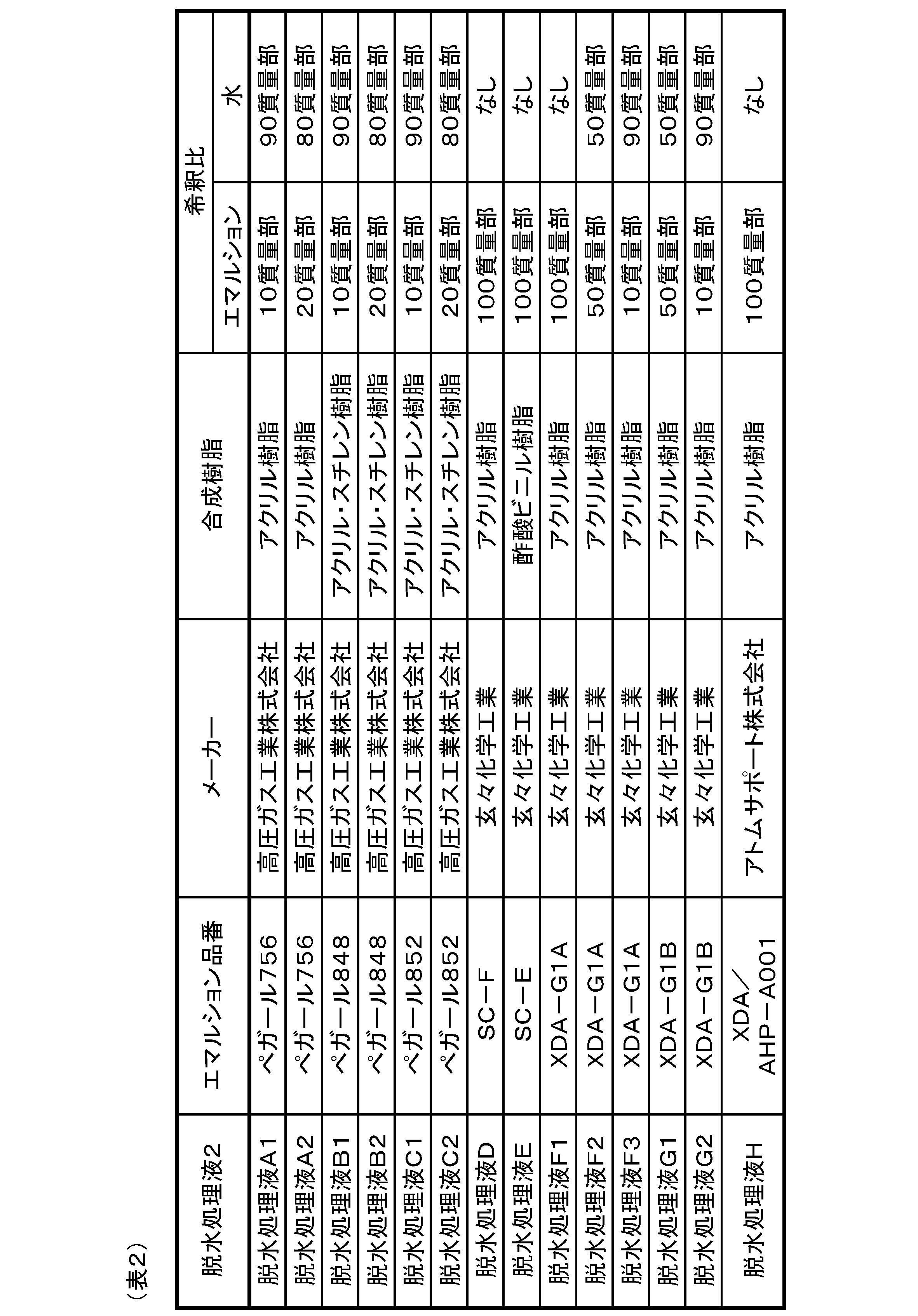
- ⁇ Dehydration treatment liquid 2> As shown in Table 2, the dehydration liquid 2 used in this example is obtained by appropriately diluting emulsions containing various synthetic resins with water.
- ⁇ Mixing step S1> In the mixing step S1, as shown in Experimental Examples 1 to 10 in Table 1, various dehydrating liquids 2 are added to the dehydrated cake 1 at a mass ratio shown in Table 1. Thereafter, these are stirred for 5 to 10 minutes to form a mixture 3 of the dehydrated cake 1 and the dehydrated liquid 2 as shown in FIG. While stirring in the mixing step S1, as shown in FIG. 3, the surface of the granular material 10 in the mixture 3 and the dehydration treatment liquid 2 are in contact with each other. At the end of the mixing step S1, the surface of the granular material 10 is uniformly covered with the dehydration liquid 2.
- the paste-like mixture 3 obtained in the mixing step S1 is shaped into a plate having a thickness of 5 mm. Then, as shown in FIG. 1, the cut surface 30 is formed using a cutter so that it may be divided into a size of about 20 mm square when viewed from the thickness direction of the mixture 3. Thereby, the mixture 3 is isolate
- ⁇ Drying step S3> In the drying step S3, the mixture 3 separated into a size of about 20 mm square in the shaping step S2 is dried, thereby forming a synthetic resin film 21 formed by drying the dehydration liquid 2 on the surface of the granular material 10. The moisture of the granular material 10 is evaporated. As a result, as shown in FIG. 4, a coated granule 310 composed of the granule 10 having a reduced moisture content and the synthetic resin film 21 covering the surface thereof is formed. Further, as the mixture 3 contracts with drying, the mixture 3 is naturally divided along the cut surface 30 as shown in FIG.
- blow drying was adopted as a method of drying the mixture 3.
- Blow drying is a method in which the mixture 3 is placed in a room temperature environment and air is blown to the mixture 3 using a blower or the like to dry.
- the room temperature fluctuated between 20-38 ° C.
- the wind speed at a position 50 cm away from the blower was in the range of 1.9 to 5.2 m / s.
- the mixing step S ⁇ b> 1 the mixture 3 of the granular material 10 and the dehydrating liquid 2 is formed, and the dehydrating liquid 2 is brought into contact with the surface of the granular material 10. Thereby, as shown in FIG. 3, the surface of the granular material 10 can be uniformly covered with the dehydration treatment liquid 2.
- the drying step S3 by drying the mixture 3, the moisture contained in the granular material 10 evaporates with the drying of the dehydration liquid 2.
- the drying step S3 is performed by forcibly sending air toward the mixture 3. As a result, as shown in Table 1, evaporation of moisture contained in the granular material 10 is promoted, and the drying speed of the mixture 3 can be improved.
- the drying step S3 the dehydration treatment liquid 2 and the granular body 10 are simultaneously dried, so that the moisture content of the granular body 10 can be reduced and the synthetic resin film 21 can be formed simultaneously. As a result, the manufacturing process of the dry combustible substance 31 can be further simplified.
- the dehydration liquid 2 contains an acrylic resin or a vinyl acetate resin as a synthetic resin. Since the dehydration treatment liquid 2 containing these resins has a relatively large effect of promoting the drying of the granular material 10, it can be suitably used for drying the granular material 10. Further, since the synthetic resin film 21 made of these resins has water repellency, the moisture absorption of the dry combustible material 31 during storage or the like can be reduced, and an increase in the moisture content or the dry combustible material 31 can be suppressed from being sticky. As a result, it is possible to obtain a dry combustible material 31 that is easier to handle.
- the drying step S3 is performed in a state where the mixture 3 is shaped into a plate having a thickness of 10 mm or less. Therefore, the distance that moisture moves from the inside of the shaped mixture 3 toward the surface can be shortened. As a result, the drying speed of the mixture 3 can be further improved.
- a plurality of mixtures 3 are formed by forming a cut surface 30 so as to partition the mixture 3 into a desired size during shaping or after the shaping and before performing the drying step S3. It is separated into blocks. Therefore, in the drying step S3, the surface area of the mixture 3 can be increased, and the drying speed of the mixture 3 can be further improved. Further, due to the shrinkage of the mixture 3 accompanying the drying, the mixture 3 is naturally divided along the cut surface 30 as shown in FIG. Therefore, the dry combustible material 31 that is easy to handle can be obtained because the size of the obtained dry combustible material 31 is easily uniform.
- the method for producing a dry combustible material can improve the drying speed of the combustible material by a simple process.
- the dry combustible substance 31 produced by the above production method has a moisture content of 20% by mass or less, and thus has a small volume and weight and can be easily stored and transported. Moreover, since the dry combustible substance 31 has a low moisture content, it is likely to generate a relatively large amount of heat when used as a fuel. Furthermore, the presence of the synthetic resin film 21 can prevent the dry combustible substance 31 from absorbing moisture during storage and increasing the moisture content or being sticky. Therefore, the dry combustible substance 31 is very easy to handle.
- the dewatered cake 1 of sewage sludge is used as a combustible substance, it is easy to store for a long time while suppressing spoilage by reducing the water content by the above production method. In addition, by reducing the water content, a specific odor can be reduced.
- the amount of heat when burned is preferably 3700 to 5000 kcal / kg as described above.
- the amount of heat generated during combustion was measured using the dry combustible material 31 obtained in Experimental Example 9 of this example, the amount of heat generated during combustion was 5130 kcal / kg. This value is slightly larger than the upper limit of the above specific range.
- a method of appropriately adjusting the conditions of the mixing step S1, the drying step S3, etc. so as to increase the moisture content of the dry combustible substance 31.
- Example 2 This example is an example in which a dry combustible material 31 was manufactured using sake lees as the combustible material in Example 1. That is, using the sake lees having a water content of 90.3% by mass instead of sewage sludge as the combustible material, the mixing step S1, the shaping step S2, and the drying step S3 were performed in the same manner as in Example 1. Thereby, as shown in Experimental Example 11 of Table 3, a dry combustible substance 31 having a water content of 12.8% by mass was obtained.
- Experimental Example 12 in Table 3 is an example in which drying was performed by the same procedure as Experimental Example 11 except that the dehydration treatment liquid 2 was not added.
- FIG. 5 shows the result.
- the horizontal axis represents the elapsed time from the start of drying
- the vertical axis represents the measured moisture content value.
- the broken line in FIG. 5 shows the value of the moisture content measured 12 hours after the start of drying for the sake lees of Experimental Example 12.
- the sake lees used in this example are solids discharged during the brewing process of Japanese sake, and are composed of granules 10 made of residue such as sake rice. Therefore, as is known from Table 3 and FIG. 5, the drying rate can be further improved by using the above production method. In addition, the same effects as those of the first embodiment can be achieved.
- Example 3 animal and plant waste is used as the combustible material in Example 1.
- a dry combustible material 31 was produced using a Korean grass or jellyfish as the combustible material.
- the Korai turf used what was cut with a lawn mower or the like, and the water content before mixing with the dehydration liquid 2 was 64.6% by mass.
- the jellyfish used what was cut
- the mixing step S1 was performed on the above-mentioned Goryeo turf or jellyfish in the same manner as in Example 1 to obtain a mixture 3 whose surface was coated with the dehydration liquid 2.
- the mixture 3 was spread evenly in a suitable container, and the mixture 3 obtained in the same manner as in Example 1 was blown and dried.
- a dry combustible substance 31 having a moisture content of 11.4% by mass produced using ginseng grass and a moisture content of 9.6% by mass produced using jellyfish. Of dry combustible material 31 was obtained.
- Experimental Example 22 in Table 4 is an example in which drying was performed by the same procedure as Experimental Example 21 except that the dehydrating solution 2 was not added.
- Experimental Example 24 in Table 4 is an example in which drying was performed according to the same procedure as Experimental Example 23 except that the dehydrating solution 2 was not added.
- the moisture content during air blowing drying was measured every hour for Experimental Examples 21 and 22 using Goryeo grass.
- the result is shown in FIG.
- the horizontal axis represents the elapsed time from the start of drying, and the vertical axis represents the measured moisture content.
- the above production method is effective not only for sewage sludge and food waste but also for animal and plant waste.
- combustible materials other than those shown in Examples 1 to 3 can be used in the above manufacturing method.
- lignite can be used instead of sewage sludge as the combustible material in Example 1.
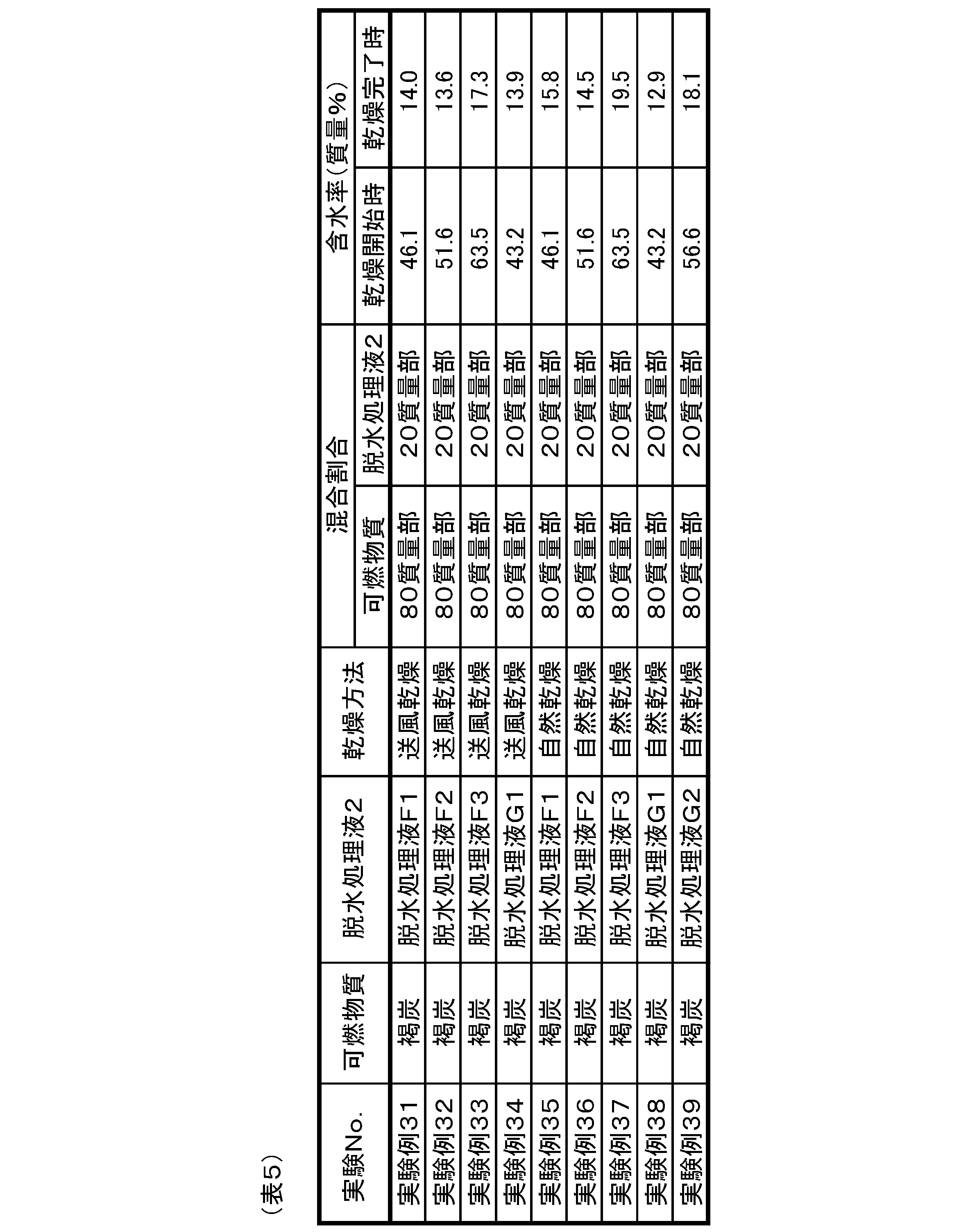
- Example 1 the example of an experiment conducted preliminary using lignite is shown.
- lignite before mixing with the dehydration treatment liquid 2, lignite was pulverized using a pulverizer to obtain a granular material 10 made of lignite and having a particle size of 1 mm or less.
- the lignite used in this example had a moisture content of about 20% by mass before mixing with the dehydration liquid 2, but the moisture content of the lignite immediately after mining is usually about 50 to 60% by mass. . Therefore, before mixing the dehydration processing liquid 2 with the granular material 10, moisture was added to the granular material 10 to adjust the water content.
- the drying step S3 in this example employs two types of methods, namely air drying and natural drying as in Example 1.
- Natural drying is a method in which the mixture 3 is dried in a room temperature environment without forced air blowing. In this example, the room temperature fluctuated between 20-38 ° C.
Landscapes
- Chemical & Material Sciences (AREA)
- Oil, Petroleum & Natural Gas (AREA)
- Organic Chemistry (AREA)
- Life Sciences & Earth Sciences (AREA)
- General Life Sciences & Earth Sciences (AREA)
- Environmental & Geological Engineering (AREA)
- Geochemistry & Mineralogy (AREA)
- Geology (AREA)
- Agronomy & Crop Science (AREA)
- Solid Fuels And Fuel-Associated Substances (AREA)
- Processing Of Solid Wastes (AREA)
- Engineering & Computer Science (AREA)
- Combustion & Propulsion (AREA)
Abstract
Description
上記粒状体の表面に上記脱水処理液が乾燥してなる合成樹脂皮膜を形成するとともに上記粒状体の水分を蒸発させることにより、含水率を低減させた上記粒状体と、その表面を被覆する上記合成樹脂皮膜とからなる被覆粒状体を形成し、該被覆粒状体から構成される乾燥可燃物質を得る乾燥工程とを有することを特徴とする乾燥可燃物質の製造方法にある。
w=h/W×100 (1)
本例は、上記可燃物質として下水汚泥を用いて乾燥可燃物質を製造した例である。本例においては、図1に示すように、可燃物質として下水汚泥の脱水ケーキ1を用い、脱水ケーキ1と脱水処理液2とを混合して混合物3を形成する混合工程S1を行った。混合工程S1の後、混合物3を板状に整形するとともに複数のブロック状に分離する整形工程S2を行った。その後、混合物3を乾燥させる乾燥工程S3を行い、乾燥可燃物質31を得た。以下、本例において使用した可燃物質、脱水処理液2、各工程の詳細及び含水率の測定方法について説明する。
本例において用いた可燃物質は、予め圧搾機等により固体状に成形された下水汚泥の脱水ケーキ1である。脱水ケーキ1は、図2に示すように、種々の粒径を有する粒状体10が凝集して構成されており、各々の粒状体10が水分を含有している。また、これらの粒状体10の間に形成される空間100に水分が保持されやすくなっている。なお、本例で用いた脱水ケーキ1の含水率は、表1に示す通り67.0~75.8質量%であった。
本例において用いた脱水処理液2は、表2に示すように、種々の合成樹脂を含有するエマルションを水で適宜希釈したものである。
混合工程S1では、表1の実験例1~10に示すように、脱水ケーキ1に対して種々の脱水処理液2を表1に示す質量比で添加する。その後、これらを5~10分間撹拌することにより、図1に示すように、脱水ケーキ1と脱水処理液2との混合物3を形成する。混合工程S1において撹拌を行っている間、図3に示すように、混合物3中の粒状体10の表面と脱水処理液2とが接触する。そして、混合工程S1の終了時には、粒状体10の表面を脱水処理液2がむらなく被覆した状態となる。
整形工程S2では、混合工程S1により得られたペースト状の混合物3を、厚み5mmの板状に整形する。その後、図1に示すように、混合物3の厚み方向から見て20mm角程度の大きさに区画されるようにカッターを用いて切断面30を形成する。これにより、混合物3は、複数のブロック状に分離される。
乾燥工程S3では、整形工程S2において20mm角程度の大きさに分離された混合物3を乾燥させることにより、粒状体10の表面に脱水処理液2が乾燥してなる合成樹脂皮膜21を形成するとともに粒状体10の水分を蒸発させる。これにより、図4に示すように、含水率を低減させた粒状体10と、その表面を被覆する合成樹脂皮膜21とからなる被覆粒状体310が形成される。また、乾燥に伴って混合物3が収縮することにより、図1に示すように、混合物3が切断面30に沿って自然に分割される。その結果、合成樹脂皮膜21を介して互いに接着された複数の被覆粒状体310よりなる乾燥可燃物質31を得る。本例では、混合物3を乾燥させる方法として、送風乾燥を採用した。送風乾燥は、混合物3を室温環境下におき、送風機等を用いて混合物3に対して空気を送風して乾燥させる方法である。なお、本例において、室温は20~38℃の間で変動した。また、本例において用いた送風機は、送風機から50cm離れた位置の風速が1.9~5.2m/sの範囲であった。
測定対象となる混合物3を5g採取し、加熱乾燥式水分計(エー・アンド・デイ株式会社製、ML-50)を用いて上記式(1)により算出される含水率を測定した。含水率の測定結果は、表1に示す通りである。なお、含水率の測定は、各々の実験例について、脱水ケーキ1と脱水処理液2とを混合する前(混合前)、混合物3の送風乾燥を行う前(乾燥開始時)及び送風乾燥を12時間行った後(乾燥完了時)に行った。

本例は、実施例1における可燃物質として、酒粕を用いて乾燥可燃物質31を製造した例である。すなわち、可燃物質として下水汚泥に換えて含水率が90.3質量%である酒粕を用い、実施例1と同様に混合工程S1、整形工程S2及び乾燥工程S3を行った。これにより、表3の実験例11に示すように、含水率12.8質量%の乾燥可燃物質31を得た。なお、表3の実験例12は、脱水処理液2を添加しない以外は実験例11と同様の手順により乾燥を行った例である。

本例は、実施例1における可燃物質として、動植物性の廃棄物を使用した例である。
本例においては、表4に示すように、可燃物質として高麗芝またはくらげを用いて乾燥可燃物質31を製造した。高麗芝は、芝刈り機等により刈り取ったものを用いており、脱水処理液2との混合前の含水率は64.6質量%であった。また、くらげは、予め10mm角程度に切断したものを用いており、脱水処理液2との混合前の含水率は84.8質量%であった。

Claims (15)
- 水分を含んだ可燃物質よりなる多数の粒状体と、合成樹脂を含有するエマルションからなる脱水処理液とを混合して混合物を形成するとともに、該混合物中の上記粒状体の表面に上記脱水処理液を接触させる混合工程と、
上記粒状体の表面に上記脱水処理液が乾燥してなる合成樹脂皮膜を形成するとともに上記粒状体の水分を蒸発させることにより、含水率を低減させた上記粒状体と、その表面を被覆する上記合成樹脂皮膜とからなる被覆粒状体を形成し、該被覆粒状体から構成される乾燥可燃物質を得る乾燥工程とを有することを特徴とする乾燥可燃物質の製造方法。 - 請求項1に記載の乾燥可燃物質の製造方法において、上記乾燥工程は、上記混合物に向けて強制的に空気を送ることにより行うことを特徴とする乾燥可燃物質の製造方法。
- 請求項1または2に記載の乾燥可燃物質の製造方法において、上記乾燥工程は、上記乾燥可燃物質の含水率が20質量%以下となるまで行うことを特徴とする乾燥可燃物質の製造方法。
- 請求項1~3のいずれか1項に記載の乾燥可燃物質の製造方法において、上記脱水処理液は、上記合成樹脂としてアクリル樹脂、ウレタン樹脂または酢酸ビニル樹脂を含有することを特徴とする乾燥可燃物質の製造方法。
- 請求項1~4のいずれか1項に記載の乾燥可燃物質の製造方法において、上記混合工程の後、上記混合物を厚さ10mm以下の板状に整形した状態で上記乾燥工程を行うことを特徴とする乾燥可燃物質の製造方法。
- 請求項5に記載の乾燥可燃物質の製造方法において、上記混合物を板状に整形するとともに複数のブロック状に分離した状態で上記乾燥工程を行うことを特徴とする乾燥可燃物質の製造方法。
- 請求項1~6のいずれか1項に記載の乾燥可燃物質の製造方法において、上記可燃物質は下水汚泥であることを特徴とする乾燥可燃物質の製造方法。
- 請求項1~6のいずれか1項に記載の乾燥可燃物質の製造方法において、上記可燃物質は食品廃棄物であることを特徴とする乾燥可燃物質の製造方法。
- 請求項1~6のいずれか1項に記載の乾燥可燃物質の製造方法において、上記可燃物質は褐炭であることを特徴とする乾燥可燃物質の製造方法。
- 請求項9に記載の乾燥可燃物質の製造方法において、上記粒状体の粒径は5mm以下であることを特徴とする乾燥可燃物質の製造方法。
- 請求項1~10のいずれか1項に記載の乾燥可燃物質の製造方法において、上記乾燥可燃物質は、燃焼させた際の熱量が3700~5000kcal/kgであることを特徴とする乾燥可燃物質の製造方法。
- 含水率が20質量%以下の可燃物質からなる粒状体と、該粒状体の表面を被覆する合成樹脂皮膜とからなる被覆粒状体から構成されていることを特徴とする乾燥可燃物質。
- 請求項12に記載の乾燥可燃物質において、上記合成樹脂皮膜はアクリル樹脂、ウレタン樹脂、または酢酸ビニル樹脂からなることを特徴とする乾燥可燃物質。
- 請求項12または13に記載の乾燥可燃物質において、上記粒状体は、含水率を20質量%以下まで低減させた下水汚泥または食品廃棄物であることを特徴とする乾燥可燃物質。
- 請求項12または13に記載の乾燥可燃物質において、上記粒状体は、含水率を20質量%以下まで低減させた褐炭であることを特徴とする乾燥可燃物質。
Priority Applications (5)
| Application Number | Priority Date | Filing Date | Title |
|---|---|---|---|
| EP14783757.9A EP3112445A4 (en) | 2014-02-25 | 2014-02-25 | Method for manufacturing dried combustible substance and dried combustible substance |
| RU2014147612/04A RU2604724C2 (ru) | 2014-02-25 | 2014-02-25 | Способ производства высушенного горючего материала |
| PCT/JP2014/054410 WO2015128923A1 (ja) | 2014-02-25 | 2014-02-25 | 乾燥可燃物質の製造方法及び乾燥可燃物質 |
| KR1020147033243A KR101637802B1 (ko) | 2014-02-25 | 2014-02-25 | 건조 가연 물질의 제조 방법 |
| US14/391,960 US10072226B2 (en) | 2014-02-25 | 2014-02-25 | Method for manufacturing dried combustible material and dried combustible material |
Applications Claiming Priority (1)
| Application Number | Priority Date | Filing Date | Title |
|---|---|---|---|
| PCT/JP2014/054410 WO2015128923A1 (ja) | 2014-02-25 | 2014-02-25 | 乾燥可燃物質の製造方法及び乾燥可燃物質 |
Publications (1)
| Publication Number | Publication Date |
|---|---|
| WO2015128923A1 true WO2015128923A1 (ja) | 2015-09-03 |
Family
ID=53881622
Family Applications (1)
| Application Number | Title | Priority Date | Filing Date |
|---|---|---|---|
| PCT/JP2014/054410 WO2015128923A1 (ja) | 2014-02-25 | 2014-02-25 | 乾燥可燃物質の製造方法及び乾燥可燃物質 |
Country Status (5)
| Country | Link |
|---|---|
| US (1) | US10072226B2 (ja) |
| EP (1) | EP3112445A4 (ja) |
| KR (1) | KR101637802B1 (ja) |
| RU (1) | RU2604724C2 (ja) |
| WO (1) | WO2015128923A1 (ja) |
Cited By (1)
| Publication number | Priority date | Publication date | Assignee | Title |
|---|---|---|---|---|
| EP2933318A4 (en) * | 2014-03-03 | 2015-10-28 | Aisaku Co Ltd | DEVICE FOR PREPARING A SOLID FUEL AND METHOD FOR PRODUCING A SOLID FUEL |
Citations (7)
| Publication number | Priority date | Publication date | Assignee | Title |
|---|---|---|---|---|
| JPS58127794A (ja) * | 1982-01-25 | 1983-07-29 | Hitachi Zosen Corp | 低品位炭のコ−テイング法 |
| JPS58148050U (ja) * | 1982-03-30 | 1983-10-05 | 井川 進太郎 | 固形燃料 |
| JPS62591A (ja) * | 1986-06-13 | 1987-01-06 | Shintaro Igawa | 固形燃料の製造方法 |
| JPH1135959A (ja) * | 1997-07-22 | 1999-02-09 | Kawasaki Heavy Ind Ltd | 湿潤有機性廃棄物から成型物を製造する方法及び装置 |
| JP2008081568A (ja) | 2006-09-27 | 2008-04-10 | Nippon Steel Engineering Co Ltd | バイオマス燃料及びその製造方法 |
| JP2011153282A (ja) * | 2010-01-27 | 2011-08-11 | Rebran Kk | リサイクルによる固形化燃料の製造方法 |
| JP2013072013A (ja) * | 2011-09-28 | 2013-04-22 | Hitachi Ltd | 廃棄物から燃料ペレットを作成する方法、廃棄物から燃料ペレットを作成する装置及びその装置を搭載した電気自動車 |
Family Cites Families (18)
| Publication number | Priority date | Publication date | Assignee | Title |
|---|---|---|---|---|
| US1960917A (en) * | 1932-09-09 | 1934-05-29 | Delaware Chemical Engineering | Process of treating coal |
| GB874686A (en) | 1958-03-10 | 1961-08-10 | American Cyanamid Co | Process of protecting coal against deterioration |
| US4236897A (en) * | 1978-09-18 | 1980-12-02 | Johnston Ian F | Fuel pellets |
| US4304573A (en) | 1980-01-22 | 1981-12-08 | Gulf & Western Industries, Inc. | Process of beneficiating coal and product |
| GB2068410A (en) | 1980-01-22 | 1981-08-12 | Gulf & Western Industries | Benefication of coal by polymer coating the particles thereof |
| US4332593A (en) | 1980-01-22 | 1982-06-01 | Gulf & Western Industries, Inc. | Process for beneficiating coal |
| US4389218A (en) | 1981-09-16 | 1983-06-21 | Blackfire Coal Products | Production of solid fuel shapes from coal fines |
| US4485584A (en) * | 1983-08-12 | 1984-12-04 | Raulerson Products Manufacturing Company, Inc. | Ignitable fuel and fire starting composition |
| EA000979B1 (ru) | 1998-04-06 | 2000-08-28 | Валерий Григорьевич Лурий | Формованное топливо (варианты) и способы его получения |
| JP4438329B2 (ja) | 2002-06-26 | 2010-03-24 | 三菱マテリアル株式会社 | 有機物を含む廃棄物の処理方法 |
| JP5416888B2 (ja) | 2007-06-04 | 2014-02-12 | 日立造船株式会社 | バイオソリッド燃料およびバイオソリッド燃料の製造方法 |
| JP5110699B2 (ja) | 2008-03-18 | 2012-12-26 | 太平洋セメント株式会社 | 可燃性廃棄物の燃料化システム及び燃料化方法 |
| JP4593657B2 (ja) | 2008-07-11 | 2010-12-08 | 株式会社クリエイティブ | 固体燃料 |
| JP2010024393A (ja) | 2008-07-23 | 2010-02-04 | Eco-Material Inc | 草本類、木材枝葉を主原料とするバイオマス燃料及びその製造方法 |
| TW201026837A (en) | 2008-09-17 | 2010-07-16 | Bdi Bio Diesel Internat Ag | Process for obtaining combustibles and fuels, respectively |
| KR101221851B1 (ko) * | 2010-04-21 | 2013-01-15 | 한국에너지기술연구원 | 바인더 물질과 탄소원이 혼합된 고체 연료를 제조하는 방법 및 그 방법에 의해 제조된 고체 연료 |
| EP2744878A1 (en) | 2011-08-19 | 2014-06-25 | Celanese Emulsions GmbH | Fuel pellets and briquettes, their production and use |
| JP5642131B2 (ja) | 2012-09-20 | 2014-12-17 | 株式会社アクト | 乾燥可燃物質の製造方法 |
-
2014
- 2014-02-25 RU RU2014147612/04A patent/RU2604724C2/ru active
- 2014-02-25 EP EP14783757.9A patent/EP3112445A4/en not_active Withdrawn
- 2014-02-25 US US14/391,960 patent/US10072226B2/en active Active
- 2014-02-25 KR KR1020147033243A patent/KR101637802B1/ko active IP Right Grant
- 2014-02-25 WO PCT/JP2014/054410 patent/WO2015128923A1/ja active Application Filing
Patent Citations (7)
| Publication number | Priority date | Publication date | Assignee | Title |
|---|---|---|---|---|
| JPS58127794A (ja) * | 1982-01-25 | 1983-07-29 | Hitachi Zosen Corp | 低品位炭のコ−テイング法 |
| JPS58148050U (ja) * | 1982-03-30 | 1983-10-05 | 井川 進太郎 | 固形燃料 |
| JPS62591A (ja) * | 1986-06-13 | 1987-01-06 | Shintaro Igawa | 固形燃料の製造方法 |
| JPH1135959A (ja) * | 1997-07-22 | 1999-02-09 | Kawasaki Heavy Ind Ltd | 湿潤有機性廃棄物から成型物を製造する方法及び装置 |
| JP2008081568A (ja) | 2006-09-27 | 2008-04-10 | Nippon Steel Engineering Co Ltd | バイオマス燃料及びその製造方法 |
| JP2011153282A (ja) * | 2010-01-27 | 2011-08-11 | Rebran Kk | リサイクルによる固形化燃料の製造方法 |
| JP2013072013A (ja) * | 2011-09-28 | 2013-04-22 | Hitachi Ltd | 廃棄物から燃料ペレットを作成する方法、廃棄物から燃料ペレットを作成する装置及びその装置を搭載した電気自動車 |
Non-Patent Citations (1)
| Title |
|---|
| See also references of EP3112445A4 * |
Cited By (2)
| Publication number | Priority date | Publication date | Assignee | Title |
|---|---|---|---|---|
| EP2933318A4 (en) * | 2014-03-03 | 2015-10-28 | Aisaku Co Ltd | DEVICE FOR PREPARING A SOLID FUEL AND METHOD FOR PRODUCING A SOLID FUEL |
| US10557097B2 (en) | 2014-03-03 | 2020-02-11 | Aisaku Co., Ltd. | Solid fuel manufacturing apparatus and method for manufacturing solid fuel |
Also Published As
| Publication number | Publication date |
|---|---|
| US20150240177A1 (en) | 2015-08-27 |
| RU2014147612A (ru) | 2016-06-20 |
| EP3112445A4 (en) | 2017-09-27 |
| US10072226B2 (en) | 2018-09-11 |
| KR101637802B1 (ko) | 2016-07-07 |
| KR20150113812A (ko) | 2015-10-08 |
| RU2604724C2 (ru) | 2016-12-10 |
| EP3112445A1 (en) | 2017-01-04 |
Similar Documents
| Publication | Publication Date | Title |
|---|---|---|
| KR101539224B1 (ko) | 바이오메스 고형연료의 제조방법 | |
| JP5642131B2 (ja) | 乾燥可燃物質の製造方法 | |
| JP2014098097A (ja) | 固形燃料の製造方法及び固形燃料 | |
| KR20110005100A (ko) | 고체연료의 제조방법 | |
| KR101389440B1 (ko) | 분뇨 슬러지의 입자화 및 발효화를 통한 퇴비 제조 방법 및 이에 의해 제조된 퇴비 | |
| JP6161242B2 (ja) | 混合燃料の製造方法 | |
| US20130276363A1 (en) | Moisture Resistant Biomass Fuel Compact and Method of Manufacturing | |
| WO2015128923A1 (ja) | 乾燥可燃物質の製造方法及び乾燥可燃物質 | |
| RU2551856C1 (ru) | Способ глубокой переработки растительного органического топлива без использования химических скрепляющих компонентов и брикетированное топливо | |
| WO2014152931A1 (en) | Moisture resistant biomass fuel compact and method of manufacturing | |
| JP2014062155A5 (ja) | ||
| TWI531425B (zh) | Biological sludge for the production of biomass fuels | |
| JP2008081568A (ja) | バイオマス燃料及びその製造方法 | |
| JP6243982B2 (ja) | 混合燃料用の成型物の製造方法 | |
| RU2631073C2 (ru) | Способ получения гранулированной древесной золы | |
| JP2014098098A (ja) | 固形燃料、その製造方法及び混合燃料の製造方法 | |
| JP6283727B2 (ja) | 混合燃料の製造方法 | |
| JP6283724B2 (ja) | 混合燃料の製造方法 | |
| WO2013163127A1 (en) | Moisture resistant biomass fuel compact and method of manufacturing | |
| JP6178101B2 (ja) | 高含水有機汚泥を使用した固形燃料製造方法 | |
| JP6283721B2 (ja) | 混合燃料の製造方法 | |
| JP6283726B2 (ja) | 混合燃料の製造方法 | |
| JP6283722B2 (ja) | 混合燃料の製造方法 | |
| JP6283725B2 (ja) | 混合燃料用の成型物の製造方法 | |
| JP6283723B2 (ja) | 混合燃料の製造方法 |
Legal Events
| Date | Code | Title | Description |
|---|---|---|---|
| WWE | Wipo information: entry into national phase |
Ref document number: 14391960 Country of ref document: US |
|
| REEP | Request for entry into the european phase |
Ref document number: 2014783757 Country of ref document: EP |
|
| WWE | Wipo information: entry into national phase |
Ref document number: 2014783757 Country of ref document: EP |
|
| ENP | Entry into the national phase |
Ref document number: 2014147612 Country of ref document: RU Kind code of ref document: A Ref document number: 20147033243 Country of ref document: KR Kind code of ref document: A |
|
| NENP | Non-entry into the national phase |
Ref country code: DE |
|
| 121 | Ep: the epo has been informed by wipo that ep was designated in this application |
Ref document number: 14783757 Country of ref document: EP Kind code of ref document: A1 |
|
| NENP | Non-entry into the national phase |
Ref country code: JP |