WO2015125376A1 - Dispositif d'affichage - Google Patents
Dispositif d'affichage Download PDFInfo
- Publication number
- WO2015125376A1 WO2015125376A1 PCT/JP2014/081865 JP2014081865W WO2015125376A1 WO 2015125376 A1 WO2015125376 A1 WO 2015125376A1 JP 2014081865 W JP2014081865 W JP 2014081865W WO 2015125376 A1 WO2015125376 A1 WO 2015125376A1
- Authority
- WO
- WIPO (PCT)
- Prior art keywords
- unit
- display
- vfg
- driving force
- image
- Prior art date
Links
Images


Classifications
-
- A—HUMAN NECESSITIES
- A61—MEDICAL OR VETERINARY SCIENCE; HYGIENE
- A61B—DIAGNOSIS; SURGERY; IDENTIFICATION
- A61B1/00—Instruments for performing medical examinations of the interior of cavities or tubes of the body by visual or photographical inspection, e.g. endoscopes; Illuminating arrangements therefor
- A61B1/00002—Operational features of endoscopes
- A61B1/00043—Operational features of endoscopes provided with output arrangements
- A61B1/00045—Display arrangement
- A61B1/0005—Display arrangement combining images e.g. side-by-side, superimposed or tiled
-
- A—HUMAN NECESSITIES
- A61—MEDICAL OR VETERINARY SCIENCE; HYGIENE
- A61B—DIAGNOSIS; SURGERY; IDENTIFICATION
- A61B1/00—Instruments for performing medical examinations of the interior of cavities or tubes of the body by visual or photographical inspection, e.g. endoscopes; Illuminating arrangements therefor
- A61B1/00002—Operational features of endoscopes
- A61B1/00004—Operational features of endoscopes characterised by electronic signal processing
- A61B1/00006—Operational features of endoscopes characterised by electronic signal processing of control signals
-
- A—HUMAN NECESSITIES
- A61—MEDICAL OR VETERINARY SCIENCE; HYGIENE
- A61B—DIAGNOSIS; SURGERY; IDENTIFICATION
- A61B1/00—Instruments for performing medical examinations of the interior of cavities or tubes of the body by visual or photographical inspection, e.g. endoscopes; Illuminating arrangements therefor
- A61B1/00002—Operational features of endoscopes
- A61B1/00025—Operational features of endoscopes characterised by power management
- A61B1/00027—Operational features of endoscopes characterised by power management characterised by power supply
- A61B1/00029—Operational features of endoscopes characterised by power management characterised by power supply externally powered, e.g. wireless
-
- A—HUMAN NECESSITIES
- A61—MEDICAL OR VETERINARY SCIENCE; HYGIENE
- A61B—DIAGNOSIS; SURGERY; IDENTIFICATION
- A61B1/00—Instruments for performing medical examinations of the interior of cavities or tubes of the body by visual or photographical inspection, e.g. endoscopes; Illuminating arrangements therefor
- A61B1/00002—Operational features of endoscopes
- A61B1/00043—Operational features of endoscopes provided with output arrangements
- A61B1/00045—Display arrangement
-
- A—HUMAN NECESSITIES
- A61—MEDICAL OR VETERINARY SCIENCE; HYGIENE
- A61B—DIAGNOSIS; SURGERY; IDENTIFICATION
- A61B1/00—Instruments for performing medical examinations of the interior of cavities or tubes of the body by visual or photographical inspection, e.g. endoscopes; Illuminating arrangements therefor
- A61B1/00147—Holding or positioning arrangements
- A61B1/00148—Holding or positioning arrangements using anchoring means
-
- A—HUMAN NECESSITIES
- A61—MEDICAL OR VETERINARY SCIENCE; HYGIENE
- A61B—DIAGNOSIS; SURGERY; IDENTIFICATION
- A61B1/00—Instruments for performing medical examinations of the interior of cavities or tubes of the body by visual or photographical inspection, e.g. endoscopes; Illuminating arrangements therefor
- A61B1/00147—Holding or positioning arrangements
- A61B1/00156—Holding or positioning arrangements using self propulsion
-
- A—HUMAN NECESSITIES
- A61—MEDICAL OR VETERINARY SCIENCE; HYGIENE
- A61B—DIAGNOSIS; SURGERY; IDENTIFICATION
- A61B1/00—Instruments for performing medical examinations of the interior of cavities or tubes of the body by visual or photographical inspection, e.g. endoscopes; Illuminating arrangements therefor
- A61B1/00147—Holding or positioning arrangements
- A61B1/0016—Holding or positioning arrangements using motor drive units
-
- A—HUMAN NECESSITIES
- A61—MEDICAL OR VETERINARY SCIENCE; HYGIENE
- A61B—DIAGNOSIS; SURGERY; IDENTIFICATION
- A61B1/00—Instruments for performing medical examinations of the interior of cavities or tubes of the body by visual or photographical inspection, e.g. endoscopes; Illuminating arrangements therefor
- A61B1/00002—Operational features of endoscopes
- A61B1/00043—Operational features of endoscopes provided with output arrangements
- A61B1/00055—Operational features of endoscopes provided with output arrangements for alerting the user
Definitions
- the present invention relates to a display device for an in vivo introduction device.
- an apparatus introduced into a living body such as an endoscope
- An endoscope system in which a propulsion mechanism is added to such an in-vivo introduction device is disclosed in, for example, Japanese Patent Application Laid-Open No. 2012-191978.
- Japanese Unexamined Patent Application Publication No. 2012-191978 discloses that driving information such as the moving speed of the self-propelling device is displayed simultaneously with the display of the observation image in the endoscopic inspection system.
- monitoring the driving force of the power unit is necessary for operating the in-vivo introduction device appropriately. Is necessary.
- the driving force of the power unit is preferably shown in a manner that is visually clear and intuitively recognized.
- an object of the present invention is to provide a display device that displays the driving force of the power unit in the in vivo introduction device.
- a display device includes an insertion unit configured to be introduced into a living body, and generates a propulsive force in the insertion unit in the living body.
- a display device for an in-vivo introduction device provided with a driving force detection unit that acquires a value related to the driving force of the power unit, and a display area that changes according to the driving force.
- a display calculation unit that determines the display area of the gauge based on the value; and a display control unit that outputs a signal for displaying the gauge on a display device.
- the present invention it is possible to provide a display device that displays the driving force of the power unit in the in-vivo introduction device.
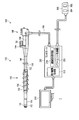
- FIG. 1 is a diagram illustrating an outline of a configuration example of an in-vivo introduction device according to each embodiment.
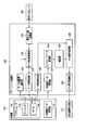
- FIG. 2 is a block diagram illustrating an outline of a configuration example according to the power unit control unit of the first embodiment.
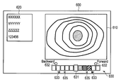
- FIG. 3A is a diagram illustrating an outline of an example of a display image according to the first embodiment.
- FIG. 3B is a diagram illustrating an outline of an example of a display image according to the first embodiment.
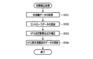
- FIG. 4 is a flowchart illustrating an outline of an example of the initial correction process according to the first embodiment.
- FIG. 5 is a flowchart illustrating an outline of an example of the motor control process according to the first embodiment.
- FIG. 1 is a diagram illustrating an outline of a configuration example of an in-vivo introduction device according to each embodiment.
- FIG. 2 is a block diagram illustrating an outline of a configuration example according to the power unit control unit of the first embodiment.
- FIG. 3A is a diagram illustrating an outline of an example of
- FIG. 6A is a diagram illustrating an outline of an example of a display image according to a first modification of the first embodiment.
- FIG. 6B is a diagram illustrating an outline of an example of a display image according to the first modification of the first embodiment.
- FIG. 7A is a diagram illustrating an outline of an example of a display image according to a second modification of the first embodiment.
- FIG. 7B is a diagram illustrating an outline of an example of a display image according to a second modification of the first embodiment.
- FIG. 8A is a diagram illustrating an outline of an example of a display image according to a third modification of the first embodiment.
- FIG. 8B is a diagram illustrating an outline of an example of a display image according to a third modification of the first embodiment.
- FIG. 9A is a diagram illustrating an outline of an example of a display image according to a fourth modification of the first embodiment.
- FIG. 9B is a diagram illustrating an outline of an example of a display image according to the fourth modification example of the first embodiment.
- FIG. 10A is a diagram illustrating an outline of an example of a display image according to a fifth modification of the first embodiment.
- FIG. 10B is a diagram illustrating an outline of an example of a display image according to a fifth modification of the first embodiment.
- FIG. 11A is a diagram illustrating an outline of an example of a display image according to a sixth modification of the first embodiment.
- FIG. 11B is a diagram illustrating an outline of an example of a display image according to a sixth modification of the first embodiment.
- FIG. 12A is a diagram illustrating an outline of an example of a display showing a display image and a visual force gauge according to the second embodiment.
- FIG. 12B is a diagram illustrating an outline of an example of a display showing a display image and a visual force gauge according to the second embodiment.
- FIG. 13 is a block diagram illustrating an outline of a configuration example of the in-vivo introduction device according to the second embodiment.
- FIG. 14A is a diagram illustrating an example of a display arrangement according to the second embodiment.
- FIG. 14B is a diagram illustrating an example of a display arrangement according to the second embodiment.
- FIG. 14C is a diagram illustrating an example of the display arrangement according to the second embodiment.
- FIG. 15A is a diagram illustrating an outline of an example of a monitor having a display image and a visual force gauge according to a modification of the second embodiment.
- FIG. 15B is a diagram illustrating an outline of an example of a monitor having a display image and a visual force gauge according to a modification of the second embodiment.
- FIG. 1 shows an outline of the configuration of the in-vivo introduction device 1 according to this embodiment.
- the in-vivo introduction device 1 includes an endoscope 100, a controller 200, a monitor 310, and an operation input unit 360.
- the endoscope 100 includes an elongated insertion portion 110 configured to be inserted into a living body.
- the endoscope 100 includes an operation unit 160 for performing various operations of the endoscope 100.
- the operation unit 160 is held by the user.
- the distal end side of the insertion portion 110 is referred to as the distal end direction
- the operation portion 160 side is referred to as the proximal end side.
- the operation unit 160 of the endoscope 100 and the controller 200 are connected by a universal cable 190.
- the insertion portion 110 includes a distal end rigid portion 112 provided on the most distal end side, a bending portion 114 provided on the proximal end side of the distal end rigid portion 112, and a serpentine tube portion 116 provided on the proximal end side of the bending portion 114.
- the bending portion 114 is configured to bend actively according to the rotation of an operation knob (not shown) provided in the operation portion 160.
- the serpentine tube portion 116 is passively bent by an external force.
- the tip rigid portion 112 is provided with an image sensor 120.
- the image sensor 120 generates an image signal based on the subject image on the distal end side of the insertion unit 110.
- the image signal acquired by the imaging element 120 is transmitted to the controller 200 via the imaging signal signal line 122 that passes through the insertion unit 110 and the universal cable 190.
- the distal end rigid portion 112 is provided with an illumination window (not shown) for illuminating the subject.
- a light guide (not shown) extending from the controller is connected to the illumination window. The light emitted from the light source provided in the controller is guided by the light guide and emitted from the illumination window. The subject is illuminated by the light emitted from the illumination window.
- the distal end rigid portion 112 is provided with an opening of a treatment instrument channel tube through which a treatment instrument such as forceps is inserted.
- a power unit 130 is provided in the serpentine tube portion 116 of the insertion portion 110.
- the power unit 130 has a cylindrical mounting unit 132 provided around the flexible tube portion 116 so as to be rotatable around the longitudinal axis of the flexible tube portion.
- Fins 134 are provided on the outer peripheral surface of the mounting unit 132.
- the fins 134 are provided in a spiral shape with the longitudinal axis of the mounting unit 132 as the center. The fin 134 rotates according to the rotation of the mounting unit 132.
- the mounting unit 132 is connected to the actuator 150 provided in the operation unit 160 via the gear in the gear box 144 and the drive shaft 146.
- the actuator 150 is operated by an operation using the operation input unit 360, the driving force is transmitted by the gear in the gear box 144 and the drive shaft 146.
- the mounting unit 132 and the fin 134 rotate clockwise and counterclockwise around their longitudinal axes.
- a propulsive force toward the distal end side or the proximal end side acts on the insertion portion 110.
- a propulsive force acts on the insertion portion 110 when the fins pull the folds present on the inner wall of the small intestine or the large intestine.
- Such a propulsive force improves the insertion property and removal property of the insertion portion 110 in the lumen.
- the monitor 310 is a general display device such as a liquid crystal display.
- the operation input unit 360 is a foot switch, for example.
- the operation input unit 360 includes a first input unit 362 and a second input unit 364 configured with switches and the like.
- the in-vivo introduction device 1 is configured such that when the first input unit 362 is turned on, the actuator 150 operates so that the fin 134 rotates, for example, clockwise.
- the in vivo introduction device 1 is configured such that when the second input unit 364 is turned on, the actuator 150 operates so that the fin 134 rotates, for example, counterclockwise.
- the controller 200 controls each part of the in-vivo introduction device 1.
- the controller 200 includes a display image generation unit 212 and an imaging signal acquisition unit 214 that acquires an image signal acquired by the imaging element 120 of the endoscope 100.
- the imaging signal acquisition unit 214 acquires an image signal from the imaging element 120, performs necessary image processing on the image, and outputs the image signal to the display image generation unit 212.
- the display image generation unit 212 generates an image signal corresponding to an image to be displayed on the monitor 310 based on the image signal acquired from the imaging signal acquisition unit 214 and information related to the in-vivo introduction device 1 described later.
- the display image generation unit 212 outputs the generated image signal to the monitor 310 and causes the monitor 310 to display an image.
- the controller 200 includes a power unit control unit 220 for controlling the operation of the power unit 130.
- the actuator 150 and the power unit controller 220 are connected by an actuator current signal signal line 156.
- the power unit controller 220 is connected to the display image generator.
- the power unit controller 220 creates an image signal for displaying information on the driving force related to the power unit 130 on the monitor 310.
- the power unit controller 220 outputs this image signal to the display image generator 212.
- the actuator 150 provided in the endoscope 100 includes an encoder 152 and a motor 154.
- the motor 154 is a power source that drives the power unit 130.
- the encoder 152 detects the drive amount of the motor 154.
- the endoscope 100 includes an endoscope data storage unit 170.
- the endoscope data storage unit 170 stores information related to the endoscope 100.
- the endoscope data storage unit 170 stores a torque limiter value of, for example, clockwise rotation and counterclockwise rotation of the motor 154.
- the power unit control unit 220 includes a motor rotation number detection unit 232, an operation input amount acquisition unit 234, a motor control calculation unit 236, a motor drive circuit 238, a motor current detection unit 240, and an endoscope data acquisition unit 242.
- VFG visual force gauge
- the motor rotation speed detector 232 is connected to the encoder 152 and detects the rotation speed of the motor 154.
- the motor rotation number detection unit 232 outputs the detected rotation number of the motor to the motor control calculation unit 236.
- the operation input amount acquisition unit 234 acquires the input amount from the operation input unit 360 to the operation input unit 360.
- the operation input amount acquisition unit 234 outputs the acquired input amount to the motor control calculation unit 236.
- the motor control calculation unit 236 performs various calculations regarding the driving of the motor 154. That is, the motor control calculation unit 236 determines the motor 154 based on the information related to the operation input amount acquired from the operation input amount acquisition unit 234 and the information related to the motor rotation number acquired from the motor rotation number detection unit 232. The driving amount is calculated. The motor control calculation unit 236 calculates a power value input to the motor based on the calculated drive amount, and outputs this power value to the motor drive circuit 238. The motor drive circuit 238 operates the motor 154 based on the power value input from the motor control calculation unit 236.
- the motor current detector 240 detects the current value input to the motor 154.
- the motor current detection unit 240 functions as a driving force detection unit that acquires a value related to the driving force of the power unit.
- the motor current detection unit 240 outputs the acquired current value to the VFG display calculation unit 248.
- the endoscope data acquisition unit 242 acquires information related to the endoscope from the endoscope data storage unit 170.
- the endoscope data acquisition unit 242 outputs the acquired information related to the endoscope 100 to the controller data storage unit 244.
- the controller data storage unit 244 stores controller data that is information related to the controller 200.
- the controller data storage unit 244 updates the controller data based on the information related to the endoscope 100 acquired by the endoscope data acquisition unit 242.
- the controller data storage unit 244 outputs the controller data to the correction unit 246.
- the correcting unit 246 corrects the calculation formula related to the VFG display based on the controller data.
- the correction unit 246 outputs the corrected calculation formula to the VFG display calculation unit 248.
- the VFG display calculation unit 248 calculates a value related to VFG display based on the current value flowing through the motor 154 acquired from the motor current detection unit 240 and the calculation formula acquired from the correction unit 246.
- the gauge of the VFG is configured such that the display area changes according to the current value.
- the VFG display calculation unit 248 outputs the calculated value related to the VFG display to the VFG display control unit 250.
- the VFG display control unit 250 generates a display signal suitable for the display image generation unit 212 to generate an image signal, and outputs the display signal to the display image generation unit 212.
- the in-vivo introduction device 1 is used for observation in a body cavity, for example.
- the user holds the operation unit 160 with the left hand and inserts the insertion unit 110 into the body of the subject while holding the serpentine unit 116 with the right hand.
- the user operates the operation input unit 360, which is a foot switch, for example, with his / her foot to rotate the fin 134 to move the insertion unit 110 forward and backward.
- the user operates the in-vivo introduction device 1 while observing the monitor 310.
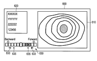
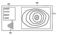
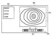
- a display image 600 as shown in FIGS. 3A and 3B is displayed on the monitor 310, for example. That is, the upper right portion of the display image 600 includes an endoscopic image 610 captured by the image sensor 120. Further, the left side of the endoscopic image 610 in the display image 600 includes character information 620 representing date and time, subject information, setting information of the endoscope 100, and the like. Furthermore, a visual force gauge (VFG) 630 according to the present embodiment is included below the endoscopic image 610 in the display image 600.
- VFG visual force gauge
- VFG 630 indicates information on the torque of the motor 154 related to the driving force of the power unit 130.
- a plurality of rectangles are arranged in the left-right direction.
- the rectangle arranged at the center is a reference rectangle 631 representing a reference position.
- the display form of the rectangle on the right side of the reference rectangle 631 changes as shown in FIG. 3A. Examples of changes in the display form include changes in the color, pattern, brightness, etc. of these rectangles. As the change in the display form, there can be various combinations of changes in color, pattern, brightness, and the like.
- the number of rectangles in which the display form changes (hereinafter referred to as the number of lighting) changes according to the magnitude of torque related to the motor 154 that drives the power unit 130.
- This torque can be calculated from the current value detected by the motor current detection unit 240.
- the number of lighting of VFG630 increases, so that a torque is large. That is, the larger the torque, the larger the display area representing the output in VFG 630.
- the arrow 633 located on the right side of FIG. Further, when the user turns off the first input unit 362, the lighting of the arrow 633 stops.
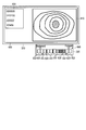
- the display form of the rectangle on the left side of the reference rectangle 631 changes as shown in FIG. 3B. Also at this time, the number of lighting depends on the torque of the motor 154. Further, when the user turns on the second input unit 364 and retracts the insertion unit 110, the arrow 633 located on the left side of FIG. Further, when the user turns off the second input unit 364, the lighting of the arrow 633 stops.
- a unit that moves the insertion portion 110 forward or backward is generally subjected to torque control.
- the current flowing through the motor 154 is controlled so that the fin 134 has a predetermined rotational speed. For this reason, for example, when there is a constricted portion in the tube into which the insertion portion 110 is inserted, adjustment can be made so that a large current flows through the motor 154 when passing through the constricted portion. When a large current flows in this way, the motor 154 may fail. Further, when a large current flows, there is a risk of damaging the tube in which the insertion portion 110 is inserted.
- the user can operate the in-vivo introduction device 1 while confirming the VFG 630 included in the display image 600 with the torque of the motor 154. As a result, failure of the in-vivo introduction device 1 and damage to the tube by the insertion unit 110 can be prevented.
- the VFG 630 is provided with a load index 632.
- the load index 632 indicates a load that may cause some abnormality when a larger load is applied to the motor 154. Therefore, the user adjusts the operation of the in-vivo introduction device 1 so that a load larger than the load indicated by the load index 632 is not applied to the motor 154. Further, the in-vivo introduction device 1 may be controlled to stop the rotation of the motor 154 when a load greater than the load indicated by the load index 632 is applied to the motor 154.
- the in-vivo introduction device 1 when the load greater than the load indicated by the load index 632 is applied to the motor 154, the in-vivo introduction device 1 causes the power supply to the motor 154 to be stopped and the drive shaft of the motor 154 to be in an unloaded state. It may be controlled. Further, in order to allow the user to visually grasp the state of the drive system, when a load larger than the load indicated by the load index 632 is applied to the motor 154, or the load in which all the rectangles of the VFG 630 are lit is the motor 154. In the case of the VFG 630, only the forward side or the backward side of the rectangle of the VFG 630 may be blinked.
- an auxiliary load index 635 is provided separately in a region sandwiching the VFG 630 from a region where the load index 632 is located.
- the load index 632 serves as a torque confirmation index when the insertion unit 110 is inserted into the body
- the auxiliary load index 635 includes the insertion unit 110 outside the body. Both indicators can be used properly, such as as a torque confirmation indicator in a certain state.
- the situation in which the torque must be confirmed while the insertion part 110 is outside the body is that there is no load in which the insertion part 110 is outside the body in order to check whether the mounting unit 132 is normally attached to the serpentine part 116.
- 3A and 3B show an example in which the number of rectangles representing the magnitude of the VFG 630 is five on each of the forward side and the backward side.
- this number may be any number, for example, 15 each.
- 3A and 3B show an example of the VFG 630 in which a plurality of rectangles are discretely arranged, but the present invention is not limited to this.
- the adjacent rectangles may be in contact with each other and continuously arranged. In this case, the display is performed so that the area of a portion that changes to a different color or the like in one rectangle changes.
- this number may be any number, for example, two.
- the VFG 630 displays the torque related to the motor 154 based on the current value acquired by the motor current detection unit 240.
- the endoscope 100 connected to the controller 200 can be changed. That is, various endoscopes 100 can be connected to the same controller 200 in accordance with usage applications. Even in the same type of endoscope 100, there are individual differences in the configuration related to the power unit 130. Therefore, the relationship between the current value acquired by motor current detector 240 and the torque displayed on VFG 630 can change. Therefore, in the present embodiment, when the in-vivo introduction device 1 is turned on, the initial correction corresponding to the endoscope 100 is performed on the relationship between the current flowing through the motor 154 and the display of the VFG 630. An initial correction process executed first when the power supply of the in vivo introduction apparatus 1 is turned on will be described with reference to a flowchart shown in FIG.
- step S101 the endoscope data acquisition unit 242 acquires endoscope data from the endoscope data storage unit 170.
- the endoscope data includes individual information of the power unit 130 such as information on a torque limiter of the motor 154 for driving the power unit 130 of the endoscope 100.
- the endoscope data acquisition unit 242 outputs the acquired endoscope data to the controller data storage unit 244.
- step S102 the controller data storage unit 244 updates the controller data based on the input endoscope data.
- the controller data storage unit 244 outputs the updated controller data to the correction unit 246.
- step S103 the correction unit 246 corrects the calculation formula for displaying the VFG 630.
- This calculation formula is a formula representing the relationship between the current value acquired by the motor current detection unit 240 and the number of lighting of the VFG 630, for example.
- the correction unit 246 outputs the corrected calculation formula to the VFG display calculation unit 248.
- step S104 the VFG display calculation unit 248 updates the data in the VFG display calculation unit 248 for the calculation formula input from the correction unit 246.
- the initial correction process ends.
- accurate torque display can be performed regardless of the type of endoscope 100 or individual differences.
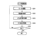
- step S201 the motor is driven. That is, the motor rotation speed detection unit 232 acquires the rotation speed of the motor from the encoder 152 provided in the actuator 150. The motor rotation number detection unit 232 outputs the acquired rotation number to the motor control calculation unit 236. The motor control calculation unit 236 calculates a current value to be passed through the motor 154 based on the input rotation speed. The motor control calculation unit 236 outputs the calculated current value to the motor drive circuit 238. The motor drive circuit 238 drives the motor 154 based on the input current value.
- step S202 the motor current detection unit 240 acquires the value of the current flowing through the motor 154.
- the motor current detection unit 240 outputs the acquired current value to the VFG display calculation unit 248.
- step S203 the VFG display calculation unit 248 calculates the number of lighting of the VFG 630 based on the calculation formula adjusted in the initial correction process described above.
- the VFG display calculation unit 248 outputs the calculated VFG lighting number to the VFG display control unit 250.
- step S204 the VFG display control unit 250 controls VFG display. That is, the VFG display control unit 250 creates image information related to the VFG 630 displayed on the monitor 310 based on the number of VFG lightings input from the VFG display calculation unit 248.
- the VFG display control unit 250 outputs the created image information to the display image generation unit 212.
- the display image generation unit 212 creates an image signal of the display image 600 including the VFG 630 based on the input image information, and causes the monitor 310 to display the display image 600.
- step S205 it is determined whether or not the motor control process is finished. When it is determined that the process is not finished, the process returns to step S201. On the other hand, when it is determined that the process is finished, the motor control process is finished.
- the information related to the output of the unit for moving the insertion portion 110 such as the power unit 130 forward or backward on the monitor 310 is displayed as the VFG 630.
- the user can operate the in-vivo introduction device 1 while grasping the torque of the motor 154 while confirming the VFG 630. As a result, it is possible to prevent the in-vivo introduction device 1 from being damaged and damaging the tube that is the insertion target.
- the VFG 630 is provided adjacent to the lower part of the endoscopic image 610. Since the user pays much attention to the endoscopic image 610, the provision of the VFG 630 near the endoscopic image 610 is effective for the user to easily recognize the VFG 630.
- the insertion unit 110 may be configured to move forward or backward as a belt provided in the insertion unit 110 rotates.
- the present technology can be used in various in-vivo introduction devices in which the driving force by the actuator is used to advance or retract the insertion unit 110.
- VFG 630 is not limited to being displayed under the endoscopic image 610 but may be displayed over the endoscopic image 610. Further, the endoscope image 610 may be displayed vertically on the left side or the right side.
- an index similar to the load index 632 is not limited to indicate a load that may cause an abnormality as described above, and may be provided to indicate another load.
- a load index indicating a load obtained when the insertion unit 110 is not inserted into the pipe, that is, when the power unit 130 is operated in a no-load state may be provided in the VFG 630.
- a load index may be provided as a plurality of rectangular marks included in the VFG. For example, when 15 rectangles are arranged, a load index may be provided for every 5 rectangles. Such a mark makes it easier for the user to grasp the magnitude of the load.
- the load index can be arranged at various positions such as above, below, or both of the rectangle in which the display form changes.
- the case where the torque of the motor 154 is evaluated by the current as the value related to the driving force of the power unit 130 is taken as an example.
- the VFG 630 may be configured to obtain values related to the driving force at various locations related to the power unit 130 and display them.
- the proportion of the area of the endoscopic image 610 in the display image 600 can be increased.
- the endoscopic image 610 has high importance among information included in the display image 600. Therefore, a large area of the endoscopic image 610 is effective in the in-vivo introduction device 1.
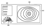
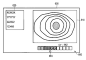
- VFG in the display image 600 is different from the first modification of the first embodiment. That is, for example, as shown in FIGS. 7A and 7B, the VFG 640 according to the present modification is arranged at the same position as the VFG 630 of the first modification of the first embodiment, but the shape is different.
- the VFG 640 according to this modification has a shape in which a plurality of sectors are arranged side by side as shown in FIGS. 7A and 7B. Also in this modification, when the insertion part 110 is moving forward, the fan-shaped display form on the right side of the VFG 640 changes as shown in FIG. 7A. When the insertion section 110 is retracted, the fan-shaped display form on the left side of the VFG 640 changes as shown in FIG. 7B. Moreover, VFG640 is comprised so that the number of lighting may differ according to the torque applied to the motor 154. FIG. Other configurations are the same as those of the first modification of the first embodiment.
- the VFG 630 takes a horizontally long form, whereas according to this modification, the VFG 640 has a small width. For this reason, the area below the character information 620 in the display image 600 can be used effectively.
- a third modification of the first embodiment will be described.
- differences from the first modification of the first embodiment will be described, and the same portions will be denoted by the same reference numerals and description thereof will be omitted.
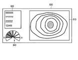
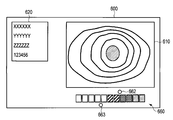
- the form of VFG in the display image 600 is different from the first modification of the first embodiment. That is, for example, as illustrated in FIGS. 8A and 8B, the VFG 650 according to the present modification is disposed at the same position as the VFG 630 according to the first modification of the first embodiment, but the shape thereof is different.
- the VFG 650 has a wider gauge width (length in the vertical direction in the figure) as the torque increases.
- the gauge on the right side of the VFG 650 is displayed as shown in FIG. 8A.
- the gauge on the left side of the VFG 640 is displayed as shown in FIG. 8B.
- VFG650 is comprised so that the number of lighting may differ according to the torque applied to the motor 154.
- FIG. Other configurations are the same as those of the first modification of the first embodiment.
- the direction and magnitude of torque can be displayed with emphasis.
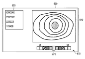
- VFG in the display image 600 is different from that in the first embodiment. That is, for example, as shown in FIGS. 9A and 9B, the VFG 660 according to the present modification is disposed at the same position as the VFG 630 of the first embodiment, but the form is different.
- the VFG 660 according to this modification has a form in which rectangles are arranged in a line.
- the number of lighting changes in accordance with the magnitude of torque in order from the left end of the VFG, as shown in FIG. 9A.
- the insertion unit 110 is retracted, the number of lighting changes in accordance with the magnitude of torque in order from the right end of the VFG, as shown in FIG. 9B. That is, in the VFG 660 according to this modification, the gauge reference position changes depending on whether the insertion portion is moving forward or backward.
- the load index according to this modification is provided with a forward load index 662 and a reverse load index 663 separately.
- more rectangles than in the first embodiment can be used to display the magnitude of the torque, so that the magnitude of the torque can be more detailed than in the first embodiment. Can be expressed.
- VFG 660 as in the present modification may be arranged under the character information 620 as in the first modification of the first embodiment.
- a fifth modification of the first embodiment will be described.
- differences from the first embodiment will be described, and the same portions will be denoted by the same reference numerals and description thereof will be omitted.
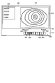
- the form of VFG in the display image 600 is different from that in the first embodiment. That is, for example, as shown in FIGS. 10A and 10B, the VFG 670 according to the present modification is arranged at the same position as the VFG 630 of the first embodiment, but the form is different.
- the position of the reference rectangle 671 representing the reference position is coincident with the center of the endoscopic image 610. That is, the position of the reference rectangle 671 matches the image representing the traveling direction of the insertion unit 110 in the endoscopic image 610.
- the shape of the left and right rectangles changes with the reference rectangle 671 as the center, and the number of the changed rectangles is the motor 154.
- the shape of the rectangle changes from both sides of the VFG 670 toward the reference rectangle 671 as shown in FIG. 10B, and the number of the changed rectangles corresponds to the torque of the motor 154.
- the eyelid in the tube displayed in the endoscopic image 610 appears to move from the center to the surrounding direction. Since the orientation of the display of the endoscopic image 610 and the display in which the shape of the rectangle changes in the left-right direction around the reference rectangle 671 of the VFG 670 match, the user can easily recognize the display of the VFG 670. Similarly, when the insertion unit 110 is retracted, the eyelid in the tube displayed in the endoscopic image 610 appears to move from the periphery to the center. Since the orientation of the display of the endoscopic image 610 and the display in which the shape of the rectangle changes from the left and right ends of the VFG 670 toward the reference rectangle 671, the user can easily recognize the display of the VFG 670.
- the form of the VFG 680 changes from top to bottom according to the driving force of the motor 154, as shown in FIG. 11A.
- the form of the VFG 680 changes from the bottom to the top according to the driving force of the motor 154, as shown in FIG. 11B.
- the display position of VFG in the first embodiment, the fourth modification example, and the fifth modification example is below the endoscopic image 610, the display position of VFG is Of course, it may be on the mirror image 610 or other positions.
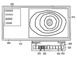
- VFG 690 is configured not to be displayed on the display image 600 of the monitor 310 but to be displayed on the display unit 320 attached to the outside of the monitor 310 as shown in FIGS. 12A and 12B. Has been.
- the display 320 is provided with a plurality of LEDs 322, for example.
- the number of LEDs 322 that are turned on in the plurality of LEDs 322 of the display 320 changes according to the magnitude of the torque of the motor 154.
- the LED 322 on the right side of the reference position is lit as shown in FIG. 12A, and when the insertion portion 110 is moving backward, the reference position is set as shown in FIG. 12B.
- the left LED 322 is also lit.
- the VFG 630 is displayed in the display image 600 displayed on the monitor 310.
- the VFG 690 is displayed by the display unit 320 attached to the outside of the monitor 310. Is done. Except for this, the display contents are the same.
- the display device 320 functions as a display device that displays VFG.
- FIG. 13 shows an outline of the configuration of the controller 200 according to this embodiment.
- the display image generation unit 212 is connected to the imaging signal acquisition unit 214 and mainly displays an endoscopic image on the monitor 310.
- the VFG display control unit 250 in the power unit control unit 220 is connected to the display 320.
- the VFG display control unit 250 controls lighting and extinguishing of each LED 322 of the display 320.
- the torque applied to the motor 154 can be presented to the user as in the first embodiment.
- the VFG can be provided outside the monitor 310 without changing the display image 600 displayed on the monitor 310 from the conventional one.
- 14A, 14B, and 14C show a display 320 provided outside the monitor 310.
- FIG. The monitor 310 is installed via an arm 313 on a trolley 311 on which the controller 200 is installed. One end of the arm 313 is installed on the back surface of the monitor 310 via a fixing mechanism, and the other end is installed on the trolley 311. The arm 313 can be operated, and the position of the monitor 310 can be changed.
- the indicator 320 is attached to a monitor 310, a trolley 311, an arm 313, a fixing mechanism of the arm 313, and the like by an attachment 315.
- the monitor 310 and the display 320 can be integrated.
- An imaging unit configured to capture an image of a living body and acquire an image
- the insertion unit configured to be introduced into the living body, and propelled by the insertion unit in the living body
- a display device for an in vivo introduction device provided with a power unit for generating force
- a driving force detector for acquiring a value relating to the driving force of the power unit
- a display calculation unit for determining the display area of the gauge configured to change the display area according to the driving force based on the value
- a display control unit that outputs a signal for causing the display device to display the gauge that is displayed in parallel with a predetermined side of the image and whose display area changes along the side
- a display device comprising: (2)
- the gauge is provided in parallel with the upper side or the lower side of the image, The gauge has a first region that is a region corresponding to the left side of the center of the side, and a second region that is a region corresponding to the right side of the center.
- the display area of the gauge changes from the center to the left side in the first region, and the second area In the region, the display area changes from the center to the right side.
- the display device according to (1) When the thrust is working in a direction in which the insertion portion is removed by the power unit, the display area of the gauge changes from the left side toward the center in the first region, The display device according to (2), wherein the display area changes from the right side toward the center in the second region.
- the gauge is provided in parallel with the left side or the right side of the image, When the driving force is working in the direction in which the insertion portion is inserted by the power unit, the display area of the gauge changes from top to bottom.
- the display device according to (1) The display device according to (1).
Landscapes
- Life Sciences & Earth Sciences (AREA)
- Health & Medical Sciences (AREA)
- Surgery (AREA)
- Engineering & Computer Science (AREA)
- Biophysics (AREA)
- Medical Informatics (AREA)
- Nuclear Medicine, Radiotherapy & Molecular Imaging (AREA)
- Optics & Photonics (AREA)
- Pathology (AREA)
- Radiology & Medical Imaging (AREA)
- Veterinary Medicine (AREA)
- Biomedical Technology (AREA)
- Heart & Thoracic Surgery (AREA)
- Physics & Mathematics (AREA)
- Molecular Biology (AREA)
- Animal Behavior & Ethology (AREA)
- General Health & Medical Sciences (AREA)
- Public Health (AREA)
- Signal Processing (AREA)
- Computer Networks & Wireless Communication (AREA)
- Endoscopes (AREA)
- Instruments For Viewing The Inside Of Hollow Bodies (AREA)
Abstract
Priority Applications (4)
| Application Number | Priority Date | Filing Date | Title |
|---|---|---|---|
| JP2015541732A JP5905171B2 (ja) | 2014-02-19 | 2014-12-02 | 表示装置 |
| EP14883411.2A EP3108792A4 (fr) | 2014-02-19 | 2014-12-02 | Dispositif d'affichage |
| CN201480067191.1A CN105828686B (zh) | 2014-02-19 | 2014-12-02 | 显示装置 |
| US15/194,639 US10004382B2 (en) | 2014-02-19 | 2016-06-28 | Display apparatus |
Applications Claiming Priority (2)
| Application Number | Priority Date | Filing Date | Title |
|---|---|---|---|
| JP2014029910 | 2014-02-19 | ||
| JP2014-029910 | 2014-02-19 |
Related Child Applications (1)
| Application Number | Title | Priority Date | Filing Date |
|---|---|---|---|
| US15/194,639 Continuation US10004382B2 (en) | 2014-02-19 | 2016-06-28 | Display apparatus |
Publications (1)
| Publication Number | Publication Date |
|---|---|
| WO2015125376A1 true WO2015125376A1 (fr) | 2015-08-27 |
Family
ID=53877905
Family Applications (1)
| Application Number | Title | Priority Date | Filing Date |
|---|---|---|---|
| PCT/JP2014/081865 WO2015125376A1 (fr) | 2014-02-19 | 2014-12-02 | Dispositif d'affichage |
Country Status (5)
| Country | Link |
|---|---|
| US (1) | US10004382B2 (fr) |
| EP (1) | EP3108792A4 (fr) |
| JP (1) | JP5905171B2 (fr) |
| CN (1) | CN105828686B (fr) |
| WO (1) | WO2015125376A1 (fr) |
Cited By (1)
| Publication number | Priority date | Publication date | Assignee | Title |
|---|---|---|---|---|
| WO2020017534A1 (fr) | 2018-07-17 | 2020-01-23 | 富士フイルム株式会社 | Composition de tube d'aide à l'insertion, tube d'aide à l'insertion, ensemble tube d'aide à l'insertion/endoscope, dispositif d'endoscope et procédé de production de tube d'aide à l'insertion |
Families Citing this family (8)
| Publication number | Priority date | Publication date | Assignee | Title |
|---|---|---|---|---|
| CN107529950B (zh) * | 2015-06-03 | 2019-07-26 | 奥林巴斯株式会社 | 安装单元 |
| WO2016194412A1 (fr) * | 2015-06-05 | 2016-12-08 | オリンパス株式会社 | Unité de montage |
| US10835106B1 (en) | 2020-02-21 | 2020-11-17 | Ambu A/S | Portable monitor |
| US11109741B1 (en) | 2020-02-21 | 2021-09-07 | Ambu A/S | Video processing apparatus |
| US11166622B2 (en) | 2020-02-21 | 2021-11-09 | Ambu A/S | Video processing apparatus |
| US10980397B1 (en) | 2020-02-21 | 2021-04-20 | Ambu A/S | Video processing device |
| EP4115789B1 (fr) | 2021-07-08 | 2023-12-20 | Ambu A/S | Dispositif de traitement d'images d'endoscope |
| US20230372673A1 (en) * | 2022-05-20 | 2023-11-23 | Boston Scientific Scimed, Inc. | Visual interface for motorized endoscope control |
Citations (4)
| Publication number | Priority date | Publication date | Assignee | Title |
|---|---|---|---|---|
| JP2008272302A (ja) * | 2007-05-01 | 2008-11-13 | Olympus Medical Systems Corp | 回転自走式内視鏡システム |
| JP2009153785A (ja) * | 2007-12-27 | 2009-07-16 | Morita Mfg Co Ltd | 診療表示装置、診療装置及び診療用表示装置 |
| WO2010090059A1 (fr) * | 2009-02-03 | 2010-08-12 | オリンパスメディカルシステムズ株式会社 | Manipulateur |
| JP2012191978A (ja) * | 2011-03-15 | 2012-10-11 | Fujifilm Corp | 内視鏡検査システム |
Family Cites Families (5)
| Publication number | Priority date | Publication date | Assignee | Title |
|---|---|---|---|---|
| JPH11332883A (ja) * | 1998-05-27 | 1999-12-07 | Olympus Optical Co Ltd | 内視鏡外科システム |
| US6522906B1 (en) * | 1998-12-08 | 2003-02-18 | Intuitive Surgical, Inc. | Devices and methods for presenting and regulating auxiliary information on an image display of a telesurgical system to assist an operator in performing a surgical procedure |
| JP4647972B2 (ja) * | 2004-11-15 | 2011-03-09 | オリンパス株式会社 | 内視鏡形状検出装置 |
| JP2010035768A (ja) * | 2008-08-04 | 2010-02-18 | Olympus Medical Systems Corp | 能動駆動式医療機器 |
| AU2011293853B2 (en) * | 2010-08-23 | 2015-08-06 | Nuvasive, Inc. | Surgical access system and related methods |
-
2014
- 2014-12-02 WO PCT/JP2014/081865 patent/WO2015125376A1/fr active Application Filing
- 2014-12-02 CN CN201480067191.1A patent/CN105828686B/zh active Active
- 2014-12-02 EP EP14883411.2A patent/EP3108792A4/fr not_active Withdrawn
- 2014-12-02 JP JP2015541732A patent/JP5905171B2/ja active Active
-
2016
- 2016-06-28 US US15/194,639 patent/US10004382B2/en active Active
Patent Citations (4)
| Publication number | Priority date | Publication date | Assignee | Title |
|---|---|---|---|---|
| JP2008272302A (ja) * | 2007-05-01 | 2008-11-13 | Olympus Medical Systems Corp | 回転自走式内視鏡システム |
| JP2009153785A (ja) * | 2007-12-27 | 2009-07-16 | Morita Mfg Co Ltd | 診療表示装置、診療装置及び診療用表示装置 |
| WO2010090059A1 (fr) * | 2009-02-03 | 2010-08-12 | オリンパスメディカルシステムズ株式会社 | Manipulateur |
| JP2012191978A (ja) * | 2011-03-15 | 2012-10-11 | Fujifilm Corp | 内視鏡検査システム |
Non-Patent Citations (1)
| Title |
|---|
| See also references of EP3108792A4 * |
Cited By (1)
| Publication number | Priority date | Publication date | Assignee | Title |
|---|---|---|---|---|
| WO2020017534A1 (fr) | 2018-07-17 | 2020-01-23 | 富士フイルム株式会社 | Composition de tube d'aide à l'insertion, tube d'aide à l'insertion, ensemble tube d'aide à l'insertion/endoscope, dispositif d'endoscope et procédé de production de tube d'aide à l'insertion |
Also Published As
| Publication number | Publication date |
|---|---|
| JP5905171B2 (ja) | 2016-04-20 |
| CN105828686B (zh) | 2017-10-17 |
| EP3108792A1 (fr) | 2016-12-28 |
| US10004382B2 (en) | 2018-06-26 |
| US20160302644A1 (en) | 2016-10-20 |
| CN105828686A (zh) | 2016-08-03 |
| EP3108792A4 (fr) | 2017-11-08 |
| JPWO2015125376A1 (ja) | 2017-03-30 |
Similar Documents
| Publication | Publication Date | Title |
|---|---|---|
| JP5905171B2 (ja) | 表示装置 | |
| EP2583616B1 (fr) | Endoscope | |
| JP5384869B2 (ja) | 内視鏡処置システム | |
| JP4197877B2 (ja) | 電動湾曲内視鏡装置及びキャリブレーション方法 | |
| JP5301867B2 (ja) | 医療用マニピュレータシステム | |
| JP5932172B2 (ja) | 内視鏡システム | |
| US10441132B2 (en) | Method of controlling endoscopes, and endoscope system | |
| WO2006090599A1 (fr) | Dispositif endoscopique | |
| WO2015118773A1 (fr) | Dispositif d'insertion | |
| WO2015005072A1 (fr) | Robot d'assistance chirurgicale | |
| JP5025319B2 (ja) | 回転自走式内視鏡システム | |
| JP5841366B2 (ja) | 医療装置 | |
| US20230380662A1 (en) | Systems and methods for responsive insertion and retraction of robotic endoscope | |
| US10314464B2 (en) | Insertion apparatus | |
| US9943957B2 (en) | Method for controlling medical manipulator | |
| JP5945654B1 (ja) | 挿入装置 | |
| JP6322095B2 (ja) | 挿入装置 | |
| JP5893382B2 (ja) | 内視鏡装置 | |
| JP6001210B2 (ja) | 内視鏡システム及び内視鏡システムのための制御装置 | |
| Litten et al. | Development of a colonoscopy add-on device for improvement of the intubation process | |
| EP3311728A1 (fr) | Appareil d'insertion, et dispositif d'insertion |
Legal Events
| Date | Code | Title | Description |
|---|---|---|---|
| ENP | Entry into the national phase |
Ref document number: 2015541732 Country of ref document: JP Kind code of ref document: A |
|
| 121 | Ep: the epo has been informed by wipo that ep was designated in this application |
Ref document number: 14883411 Country of ref document: EP Kind code of ref document: A1 |
|
| NENP | Non-entry into the national phase |
Ref country code: DE |
|
| REEP | Request for entry into the european phase |
Ref document number: 2014883411 Country of ref document: EP |
|
| WWE | Wipo information: entry into national phase |
Ref document number: 2014883411 Country of ref document: EP |