WO2015115383A1 - ラリンジアルマスク - Google Patents
ラリンジアルマスク Download PDFInfo
- Publication number
- WO2015115383A1 WO2015115383A1 PCT/JP2015/052077 JP2015052077W WO2015115383A1 WO 2015115383 A1 WO2015115383 A1 WO 2015115383A1 JP 2015052077 W JP2015052077 W JP 2015052077W WO 2015115383 A1 WO2015115383 A1 WO 2015115383A1
- Authority
- WO
- WIPO (PCT)
- Prior art keywords
- cuff
- annular
- tip
- base end
- human body
- Prior art date
- Legal status (The legal status is an assumption and is not a legal conclusion. Google has not performed a legal analysis and makes no representation as to the accuracy of the status listed.)
- Ceased
Links
Images




Classifications
-
- A—HUMAN NECESSITIES
- A61—MEDICAL OR VETERINARY SCIENCE; HYGIENE
- A61M—DEVICES FOR INTRODUCING MEDIA INTO, OR ONTO, THE BODY; DEVICES FOR TRANSDUCING BODY MEDIA OR FOR TAKING MEDIA FROM THE BODY; DEVICES FOR PRODUCING OR ENDING SLEEP OR STUPOR
- A61M16/00—Devices for influencing the respiratory system of patients by gas treatment, e.g. ventilators; Tracheal tubes
- A61M16/04—Tracheal tubes
- A61M16/0402—Special features for tracheal tubes not otherwise provided for
- A61M16/0409—Special features for tracheal tubes not otherwise provided for with mean for closing the oesophagus
-
- A—HUMAN NECESSITIES
- A61—MEDICAL OR VETERINARY SCIENCE; HYGIENE
- A61M—DEVICES FOR INTRODUCING MEDIA INTO, OR ONTO, THE BODY; DEVICES FOR TRANSDUCING BODY MEDIA OR FOR TAKING MEDIA FROM THE BODY; DEVICES FOR PRODUCING OR ENDING SLEEP OR STUPOR
- A61M16/00—Devices for influencing the respiratory system of patients by gas treatment, e.g. ventilators; Tracheal tubes
- A61M16/04—Tracheal tubes
- A61M16/0402—Special features for tracheal tubes not otherwise provided for
- A61M16/0415—Special features for tracheal tubes not otherwise provided for with access means to the stomach
Definitions
- the present invention relates to a laryngeal mask that is a medical instrument for securing an airway during general anesthesia or in a lifesaving emergency.
- the laryngeal mask is a medical device that secures the airway while blocking communication between the human esophagus and the trachea.
- the laryngeal mask is provided with an insertion tube inserted into the human body so as to communicate with the trachea and a distal end portion of the insertion tube as a basic configuration, and is set in advance from the oral cavity. And an annular cuff that can be brought into close contact with the tissue around the opening of the trachea by being expanded in a state of being inserted into the insertion position.
- the nasal cavity J1 and the oral cavity J2 of the human body J communicate with the pharynx T, and the esophagus J5 and the trachea J6 branch from the pharynx T.
- the hyoid bone J7 has a U-shape that surrounds the pharynx T from the front side (abdominal side) and the left and right sides of the human body J.
- the hyoid bone J7 is connected to the tissue around the opening of the trachea J6 with a ligament.
- a epiglottis valley J10 is formed between the back of the tongue J9 and the epiglottis J3.
- the pharynx T is below the upper pharynx T1 in the range above the bifurcation of the nasal cavity J1 and the oral cavity J2, below the upper pharynx T1 and above the epiglottis J3, and below the range below the oropharynx T2. And pharynx T3.
- the laryngeal mask is generally used as follows. With the annular cuff contracted, the insertion tube is inserted from the annular cuff side into the esophagus J5 through the oral cavity J2, and the distal end of the annular cuff passes through the branch between the esophagus J5 and the trachea J6 and reaches the constriction J4. Insert the annular cuff until The position of the annular cuff at this time is referred to as an “insertion position”. The annular cuff inserted at the insertion position is located in the pharynx T (more specifically, located from the hypopharynx T3 to the oropharynx T2).
- the annular cuff when the annular cuff is inflated, the annular cuff closely contacts the tissue around the opening of the trachea J6, and the communication between the esophagus J5 and the trachea J6 is blocked by the annular cuff. Then, in this state, the airway is secured by sending air into the trachea J6 via an insertion tube or the like through the insertion tube or leading out exhalation from the lungs.
- the ring cuff of a laryngeal mask has a wedge shape with a narrow tip as viewed from the side. Therefore, the following problems occur. That is, when the annular cuff inserted at the insertion position is expanded, the expanded annular cuff presses the human tissue, and the reaction force acts on the annular cuff. The reaction force acts on the wedge-shaped inclined surface of the annular cuff, and a component force is generated to push the annular cuff back toward the oral cavity J2. As a result, the annular cuff comes out of the insertion position when the annular cuff is expanded.
- JP 2003-511108 (particularly FIGS. 1 to 3)
- an object of the present invention is to provide a laryngeal mask in which the annular cuff is prevented from coming out of the insertion position when the annular cuff inserted at the insertion position is inflated.
- the present invention is a laryngeal mask for securing an airway while blocking communication between the human esophagus and trachea, and is inserted into the human body so as to communicate with the trachea.
- An insertion tube, and an annular cuff provided at the distal end of the insertion tube and inflated in a state of being inserted from the oral cavity into a preset insertion position so as to be in close contact with the tissue around the opening of the trachea.
- the annular cuff includes a cuff base end portion and a cuff tip end portion provided at the tip end thereof, and the cuff base end portion is in a side view more than the cuff tip end portion when the annular cuff is inflated.
- the cuff base end and the cuff tip are connected to each other so that the cuff base end protrudes forward from the cuff tip and forms a step in a side view. It is a dial mask.
- front refers to the front (abdominal side) of the human body, and more specifically refers to the side facing the opening of the trachea.
- the present invention provides a laryngeal mask that suppresses the annular cuff from being removed from the insertion position when the annular cuff inserted at the insertion position is inflated, so that the airway can be secured during general anesthesia or lifesaving emergency. Contribute to the development and improvement of medical device technology.
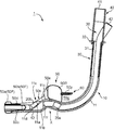
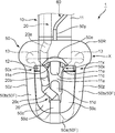
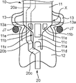
- FIG. 2 is a completed perspective view of the laryngeal mask having a different viewpoint from FIG. 1. It is a principal part top view of the said laryngeal mask. It is front sectional drawing which shows the positional relationship of a hyoid bone contact part and a hyoid bone in the state in which the cyclic
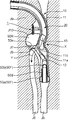
- FIG. 6 is a plan sectional view showing the positional relationship shown in FIG. 5 from the upper side (head side) of the human body. It is side surface sectional drawing which shows the state which the cyclic
- the direction of the single laryngeal mask is as shown in FIG. 1.
- the “upper” of the laryngeal mask is the “front” of the human body
- “Front” is the “bottom” of the human body
- “left” of the laryngeal mask is the “left” of the human body.
- the “front end” of the laryngeal mask is referred to as the “tip”.
- the laryngeal mask 1 includes a main body member 10, a suction tube 20, a first connector 30, a second connector 40, an annular cuff 50, and a cuff.
- the whole is configured including the tube 60 and the like.
- the main body member 10 is made by injection molding of, for example, medical soft vinyl chloride resin.
- the 1st connector 30 and the 2nd connector 40 are produced by injection molding, such as polycarbonate resin, for example.
- the annular cuff 50 is manufactured by blow molding, dipping molding, injection molding, or the like of, for example, medical soft vinyl chloride resin or medical silicone rubber.
- Main Body Member integrally includes an insertion tube 11, a support member 12, and a pair of left and right hyoid bone abutting portions 13. That is, the main body member 10 is formed by integrally molding the insertion tube 11, the support member 12, and the pair of left and right hyoid bone contact portions 13.
- the insertion tube 11 is inserted into the human body J so as to communicate with the trachea J6 (see FIG. 9).
- the insertion tube 11 is formed in a wide rectangular shape in which a cross-sectional shape (that is, a flow channel shape) in a direction orthogonal to the longitudinal direction is rounded.
- the insertion tube 11 is formed in an arc shape whose front end is curved forward in a side view, corresponding to the path from the oral cavity J2 of the human body J to the esophagus J5.
- the suction tube 20 is inserted into the insertion tube 11.
- the suction tube 20 is for sucking foreign matter in the esophagus J5 of the human body J, and has a circular channel shape.
- the channel area of the suction tube 20 is set to be significantly smaller than the channel area of the insertion tube 11.
- the first connector 30 is connected to the upper end of the insertion tube 11, and the second connector 40 is connected to the upper end of the first connector 30.
- the first connector 30 includes a cylindrical main body 31 and a pair of left and right plate-shaped protrusions 32.
- the first connector 30 is connected to the insertion tube 11 by fitting the cylindrical main body 31 into the insertion tube 11. In a state where the first connector 30 is connected to the insertion tube 11, the pair of plate-like projecting pieces 32 protrude left and right at the upper end portion of the insertion tube 11.
- the second connector 40 has a first opening 41 and a second opening 42.
- the first opening 41 is provided at the upper end of the second connector 40 and is connected to a ventilator (not shown).
- the second opening 42 protrudes obliquely rearward and upward from the rear side surface of the second connector 40 and is connected to a suction device (not shown).
- the upper end portion of the suction tube 20 is connected to the second opening 42 inside the second connector 40.
- the air supplied from the ventilator is introduced into the upper end portion of the insertion tube 11 via the first opening 41 and the two connectors 40 and 30, and from the distal end portion of the insertion tube 11 via the insertion tube 11. It is discharged outside.
- the distal end portion of the insertion tube 11 opens inside the annular cuff 50 while being surrounded by the annular cuff 50.
- exhaled air discharged from the lungs is taken into the insertion tube 11 from the distal end portion of the insertion tube 11 and led out of the body.
- the negative pressure generated by the suction device reaches the upper end portion of the suction tube 20 via the second opening 42 and extends from the distal end portion of the suction tube 20 to the outside via the suction tube 20.
- the support member 12 is continuously formed on the lower surface of the distal end portion of the insertion tube 11.
- the support member 12 is formed in a substantially rectangular flat plate shape slightly wider than the insertion tube 11 in a plan view (see FIG. 5), and is formed in an arc shape that is gently curved so as to be recessed upward in a front view. Therefore, the left and right side edge portions of the support member 12 are located slightly above the center portion of the support member 12 in the width direction.
- the support member 12 extends further to the front side than the distal end portion of the insertion tube 11.
- the hyoid bone contact portion 13 is formed on the left and right side surfaces of the distal end portion of the insertion tube 11 and is located on the rear side of the support member 12.
- the left hyoid bone contact portion 13 protrudes leftward from the left side surface of the insertion tube 11, and the right hyoid bone contact portion 13 protrudes rightward from the right side surface of the insertion tube 11.
- each hyoid bone contact portion 13 is formed in a sector shape having a central angle of approximately 70 ° to 80 ° in a side view, the arc portion faces downward, and one radial portion is the front side (supporting member 12 Side). And the flat surface including the one radius part is made into the contact surface 13a with hyoid bone J7 (refer FIG.1 and FIG.5).
- Each hyoid bone contact portion 13 is disposed at a position (hereinafter referred to as “tube arc end position”) X where the forward arc of the insertion tube 11 ends, and protrudes leftward and rightward from the support member 12.
- the left and right side edge portions of the support member 12 protrude upward as the rear side (insertion tube 11 side), and are directly connected to the left and right hyoid bone contact portions 13 (see FIG. 5).
- the distal end portion of the insertion tube 11 has a lateral width from the position where the hyoid bone contact portion 13 is disposed (that is, the tube arc end position X) to the front side in plan view.
- the width gradually decreases, and when the width is narrowed to a preset width, the preset width is maintained, and a predetermined length is further extended to the front side.
- the portion 11x in front of the tube arc end position X is referred to as a “final portion”.
- the inner surface of the circular arc of the insertion tube 11 is connected to the ceiling wall 11a of the final portion 11x, and the left and right side surfaces of the insertion tube 11 are connected to the left and right side walls 11b of the final portion 11x (see FIGS. 2, 3, and 5). Yes.
- the final portion 11x of the insertion tube 11 is formed symmetrically in plan view.
- the distal end portion of the insertion tube 11 extends obliquely downward toward the front side from the tube arc end position X (that is, the position where the hyoid contact portion 13 is disposed) in a side view.
- the ceiling wall 11a reaches the support member 12, it ends. That is, the ceiling wall 11a of the final portion 11x of the insertion tube 11 is formed in a slope shape that is inclined lower toward the front side.
- a plurality of (four in the illustrated example) openings 11c, 11d, 11e, and 11e are formed in the slope-shaped ceiling wall 11a.
- the 1st opening 11c is arrange
- the second opening 11d is disposed at the lowest portion of the ceiling wall 11a, has the second largest opening area, and has an edge formed in an arch shape.
- the pair of third openings 11e are disposed on the left and right sides of the first opening 11c, have the smallest opening area, and are formed in a substantially trapezoidal shape.
- one elliptical fourth opening 11f is also formed in each of the left and right side walls 11b of the final portion 11x of the insertion tube 11.
- the first to fourth openings 11c, 11d, 11e, and 11f are air discharge ports for discharging the air supplied from the ventilator and flowing through the insertion tube 11 to the outside. Yes (and also a breath outlet from the lungs).
- the first opening 11c having the largest opening area is a main air discharge port.
- the insertion tube 11 is formed so that the portion immediately behind the tube arc end position X is inclined upward from the tube arc end position X, and the portion immediately before the tube arc end position X is It is formed in a downward slope.
- the 1st opening 11c which is a main air discharge port is arrange
- the distal end portion of the suction tube 20 is configured as follows.
- the suction tube 20 is formed in an arc shape along the insertion tube 11 such that the distal end is curved forward in a side view.
- the suction tube 20 is inserted in the insertion tube 11 while being biased to the right.
- the suction tube 20 includes a portion (first bent portion 20a) that bends slightly upward from a portion where the forward arc ends, and a portion that extends forward by a preset length. As a result, the suction tube 20 passes through the tube arc end position X of the insertion tube 11, passes through the fourth opening 11f formed in the right side wall 11b of the final portion 11x of the insertion tube 11, and passes through the distal end of the insertion tube 11. Projects outward from the section.
- the suction tube 20 that protrudes to the outside includes a portion that bends slightly downward (second bend portion 20b), a portion that extends slightly forward, and a portion that bends leftward (third bend portion 20c). Including. Thereby, the suction tube 20 protrudes immediately in front of the second opening 11d formed in the ceiling wall 11a of the final portion 11x of the insertion tube 11. Then, the suction tube 20 includes a portion that extends to the front side by a preset length at the front side of the second opening 11d and at the center in the width direction of the support member 12 (see FIG. 5).
- the distal end portion of the suction tube 20 reaches the front portion 50a of the annular cuff 50 described below, passes through the cuff head portion 50a, and faces the outer front side.
- annular cuff 50 is provided at the distal end portion of the insertion tube 11, and expands in a state in which it is inserted from the oral cavity J2 (see FIG. 9) into a preset insertion position. This is in close contact with the tissue around the opening to block communication between the esophagus J5 and the trachea J6.
- the annular cuff 50 integrally includes a cuff base end portion 50R and a cuff tip end portion 50F provided at the tip thereof.
- the cuff tip portion 50F includes a cuff leading portion 50a and a pair of left and right cuff intermediate side portions 50b.
- the cuff base end portion 50R, the cuff leading portion 50a, and the cuff intermediate side portion 50b communicate with each other inside and are formed in an annular shape (that is, endless) as a whole.
- the material and thickness of the annular cuff 50 are set so that expansion or contraction is possible when gas is supplied to the inside or discharged from the inside.
- the cuff base end portion 50R extends linearly in the width direction (left-right direction) in plan view.
- the cuff intermediate side portion 50b extends substantially parallel to each other from the left and right side end portions of the cuff base end portion 50R to the front side.
- the cuff head portion 50a is formed in an arc shape with the center portion in the width direction projecting forward, and the left and right side end portions are respectively connected to the front end portion of the cuff intermediate side portion 50b.
- the dimensions of the cuff base end portion 50R are set to be vertical (front-rear direction) ⁇ horizontal (left-right direction) ⁇ height (vertical direction) so that the capacity when expanded is relatively large.
- the cuff base end portion 50R expands upward ("front” when the human body is inserted, that is, the front side of the human body and facing the opening of the trachea J6).
- the cuff intermediate side portion 50b of the cuff tip portion 50F has dimensions set so that the capacity during expansion is relatively small.
- the left cuff intermediate side portion 50b expands to the left during expansion, and the right cuff intermediate side portion 50b expands to the right during expansion.
- each part of the cuff leading part 50a of the cuff tip part 50F are also set so that the capacity when expanded is relatively small.
- the cuff leading portion 50a expands radially outward in the arc shape when expanded.
- the cuff base end portion 50R has a thickness (height in the vertical direction) larger than that of the cuff tip end portion 50F, and the cuff base end portion 50R and the cuff tip end portion 50F are side surfaces.
- the cuff base end portion 50R protrudes above the cuff tip end portion 50F (“front” when inserted into the human body, ie, the front side of the human body and facing the opening of the trachea J6) to form a step 50x.
- front when inserted into the human body, ie, the front side of the human body and facing the opening of the trachea J6
- the step 50x extends from the upper surface of the left and right side end portions of the cuff base end portion 50R to the upper surface of the rear end portion of the cuff intermediate side portion 50b. Due to the existence, the height in the vertical direction has plummeted.
- the cuff base end portion 50R expands in front of the human body ("front" when inserted into the human body, the side facing the opening of the trachea J6) and closely contacts the tissue on the front side of the pharynx T, and the cuff tip portion 50F (more specifically, the cuff middle side portion 50b) expands to the left and right of the human body and comes into close contact with the left and right tissues of the human body of the pharynx T.
- the side surface (cuff side surface) 50z of the cuff intermediate side portion 50b that is in close contact with the left and right tissues of the pharynx T is flat in the vertical direction and the front-rear direction so as to increase the contact area. It is formed in a shape.
- the upper surface of the cuff middle side portion 50b (the surface facing the front of the human body when the human body is inserted) is formed in parallel with the support member 12 (parallel to the front-rear direction of the human body). That is, the upper surface of the cuff intermediate side portion 50b is not formed in a wedge-shaped inclined surface.
- a recess 50e that is slightly retracted to the rear is formed on the front surface of the cuff base end portion 50R in the center in the width direction (the front surface for a single laryngeal mask).
- the recess 50e provides a space that can accommodate the epiglottis J3 on the front surface of the cuff base end 50R (see FIG. 7).
- a space 50g capable of accommodating the tongue J9 is formed between the rear surface of the cuff base end portion 50R (the rear surface of the laryngeal mask alone) and the insertion tube 11 (see FIG. 2 and FIG. 2). (See FIG. 7).
- a cuff tube mounting portion 50y for supplying an inflation gas to the annular cuff 50 is provided on the rear surface of the central portion in the width direction of the cuff base end portion 50R (the rear surface of the laryngeal mask alone).
- One end of the cuff tube 60 is connected to the attachment portion 50y, and the multiple ends of the cuff tube 60 are connected to a gas supply device (not shown).
- a cuff joint portion 50c is provided in a space surrounded by the cuff base end portion 50R, the pair of left and right cuff intermediate side portions 50b, and the cuff head portion 50a.
- the cuff joint 50c is formed across the cuff middle side 50b and the cuff head 50a.
- the cuff joint portion 50c is formed of a thin plate-like piece projecting inward of the annular cuff 50 from the lower portion of the cuff intermediate side portion 50b and the cuff head portion 50a.
- the cuff joint 50 c is placed on and joined to the upper surface of the support member 12. Thereby, the annular cuff 50 is attached to the main body member 10 via the cuff joint portion 50 c and is fixed to the distal end portion of the insertion tube 11.
- the left and right side edge portions of the support member 12 are in contact with the lower portions of the left and right cuff intermediate side portions 50 b of the annular cuff 50 from the inside of the annular cuff 50.
- the support member 12 is formed in an arc shape that is gently curved so as to be recessed upward in a front view, and the left and right side edge portions of the support member 12 are the central portions in the width direction of the support member 12. It is located slightly above.
- the support member 12 has a reaction force from the left and right sides of the human body that acts on the cuff middle side portion 50b when the cuff middle side portion 50b of the cuff tip 50F expands to the left and right of the human body (from the left and right directions).
- the cuff intermediate side portion 50b is supported from the inside of the annular cuff 50 against the compression force).
- the support member 12 has the cuff tip 50F (the cuff middle side 50b) an annular cuff so as to suppress deformation of the cuff tip 50F (more specifically, the cuff middle side 50b) due to an external force from the side. It supports from the inside of 50.
- the annular cuff 50 is provided with a suction tube mounting portion 50d.
- the suction tube attachment portion 50d is formed in the cuff joint portion 50c so as to extend in the front-rear direction continuously to the through-hole formed in the center portion in the width direction of the cuff head portion 50a and to extend in the front-rear direction.
- the distal end portion of the suction tube 20 that has reached the cuff head portion 50a passes through these tube members and through holes, and faces the front outside from the cuff head portion 50a, that is, from the tip portion of the laryngeal mask 1. .
- the cuff leading portion 50a reaches the constriction J4 past the branch portion between the esophagus J5 and the trachea J6. That is, the annular cuff 50 is inserted at the insertion position.
- the annular cuff 50 inserted in the insertion position is located in the pharynx T. Thereby, the annular cuff 50 can be accurately stopped and positioned at the insertion position based on the position of the hyoid bone J7.
- the ventilator is operated and air is fed into the trachea J6 through the insertion tube 11.
- the air supplied from the ventilator and flowing through the insertion tube 11 is discharged from the air discharge ports 11c, 11d, 11e, and 11f formed in the final portion 11x of the insertion tube 11, and sent to the trachea J6.
- exhaled air discharged from the lungs is taken into the insertion tube 11 from the air discharge ports (exhalation outlet ports) 11c, 11d, 11e, and 11f of the insertion tube 11 and led out of the body. This ensures an airway to the lungs.
- the suction device is operated as appropriate, and the foreign material in the esophagus J5 is sucked through the suction tube 20.
- a tracheal tube (not shown) is inserted into the insertion tube 11 to perform tracheal intubation. That is, tracheal intubation is performed through the laryngeal mask 1. At this time, the distal end portion of the tracheal tube exits the insertion tube 11 from the main air discharge port 11c having the largest opening area and is inserted into the trachea J6.
- FIG. 7 shows a state in which the annular cuff 50 of the laryngeal mask 1 is inserted at the insertion position and inflated in a side view of the human body.
- the cuff base end 50R is located between the back of the tongue J9 and the epiglottis J3 and expands to sink into the epiglottis valley J10. It is out.
- the epiglottis J3 is fitted and accommodated in a recess 50e (a space in which the epiglottis J3 can be accommodated) 50e formed on the front surface of the central portion in the width direction of the cuff base end 50R.
- a gap is generated between the cuff intermediate side portion 50b of the cuff distal end portion 50F and the tissue on the front side of the human body.
- the main air discharge port 11c is arranged at the tip of the ascending slope of the portion immediately behind the tube arc end position X of the insertion tube 11, and the opening of the trachea J6 is located further ahead.
- the laryngeal mask 1 which is a medical instrument for securing the airway while blocking the communication between the esophagus J5 and the trachea J6 of the human body J
- the dial mask 1 is provided at the distal end of the insertion tube 11 inserted into the human body J so as to communicate with the trachea J6, and is inflated in a state of being inserted from the oral cavity J2 into the insertion position shown in FIG. By doing so, it has an annular cuff 50 that can be in close contact with the tissue around the opening of the trachea J6.
- the anti-oral cavity includes a cuff base end portion 50R on the oral cavity J2 side and a cuff leading end portion 50a and a cuff intermediate side portion 50b. And a cuff tip 50F on the J2 side.
- the cuff base end portion 50R is thicker in side view than the cuff tip end portion 50F, and the cuff base end portion 50R and the cuff tip end portion 50F are cuff base in side view.
- the end portions 50R are connected to each other so as to protrude above the cuff tip portion 50F (in front of the human body), that is, to the side facing the opening of the trachea J6 to form a step 50x.
- a step 50x is formed between the cuff base end portion 50R and the cuff tip end portion 50F (more specifically, the cuff intermediate side portion 50b) on the front side of the human body in a side view of the human body.
- the annular cuff 50 has a wedge shape with a thin tip (on the oral cavity J2 side) in a side view of the human body. Therefore, when the annular cuff 50 inserted at the insertion position is inflated, the reaction force F acts on the annular cuff 50 from the front side of the human body, but the reaction force F acting on the wedge-shaped inclined surface causes the annular cuff 50 to act on the human body. It has the component component F1 which pushes back, and the component component F2 which tries to push back to the oral cavity J2 side. As a result, when the annular cuff 50 is inflated due to the presence of the component component F2 to be pushed back toward the mouth J2, the annular cuff 50 comes out of the insertion position.
- the annular cuff 50 is inserted into the insertion position, and the cuff base end portion 50R on the oral cavity J2 side is
- the cuff base end portion 50R is provided with a cuff distal end portion 50F on the side opposite to the oral cavity J2.
- the cuff base end 50R is thicker than the cuff tip 50F in a side view of the human body, and the cuff base end 50R and the cuff tip 50F (more specifically, the cuff intermediate side)
- a step 50x is formed on the front side of the human body in a side view of the human body 50b).
- the cuff base end 50R protrudes forward from the cuff tip 50F, and the front surface of the cuff base end 50R and the front surface of the cuff tip 50F are discontinuous with each other. Become. Therefore, an inclined surface continuously connecting the rear portion and the front portion of the annular cuff 50 as shown in FIG. 8A is not formed, and the reaction force F from the front side of the human body that acts when the annular cuff 50 expands. Mainly acts on the cuff base end portion 50R having a large thickness.
- the reaction force F against the expansion has a large ratio of acting on the cuff base end portion 50R, and the ratio of acting on the cuff tip end portion 50F is small.
- the reaction force acting on the cuff tip 50F is small, the generation of a component component that pushes the annular cuff 50 back toward the oral cavity J2 is suppressed, and the annular cuff 50 is expanded when the annular cuff 50 is expanded. Is prevented from coming out of the insertion position.
- a epiglottis valley J10 is formed between the back of the tongue J9 and the epiglottis J3.
- the cuff base end portion 50R is located between the deep part of the tongue J9 and the epiglottis J3 and tries to sink into the epiglottis valley J10.
- the wedge-shaped inclined surface continuously connecting the rear portion and the front portion of the annular cuff 50 becomes an obstacle, and the cuff base end portion 50R is Although it is difficult to sink into the epiglottis valley J10, when the step 50x is formed as shown in FIG.
- the presence of the step 50x causes the cuff base end 50R to protrude forward from the cuff tip 50F. Therefore, the penetration of the cuff base end 50R into the epiglottis valley J10 is promoted without being inhibited.
- the cuff base end portion 50R presses the cuff base end portion 50R toward the back (back side) of the human body. The reaction force acts from the back of the tongue J9.
- the reaction force has a component component that makes the annular cuff 50 face the anti-oral cavity J2 side, that is, the insertion direction.
- the annular cuff 50 is expanded, the laryngeal mask 1 becomes more difficult to come off.
- the laryngeal mask 1 is provided in which the annular cuff 50 is prevented from coming out of the insertion position when the annular cuff 50 inserted at the insertion position is expanded.
- the cuff base end portion 50R expands forward of the human body and can be brought into close contact with the tissue on the front side of the pharynx T, and the cuff distal end portion 50F (more specifically, a pair of cuffs)
- the cuff intermediate side portion 50b) has side surfaces (cuff side surfaces) 50z that expand to the left and right sides of the human body and can come into close contact with the left and right human tissues of the pharynx T.
- the cuff proximal end portion 50R having a relatively large thickness is in close contact with the tissue on the front side of the pharynx T
- the cuff distal end portion 50F having a relatively small thickness is provided on the left side and the right side of the human body of the pharynx T. Close contact with the organization. Therefore, even if the cuff tip 50F is not in close contact with the tissue on the front side of the human body, the communication between the esophagus J5 and the trachea J6 is well blocked by close contact with the left and right tissues of the human body at the cuff side surface 50z. Further, since the cuff base end portion 50R and the cuff tip end portion 50F are in close contact with the human tissue in two different directions, the annular cuff 50 is firmly and securely fixed in the pharynx T.
- the ratio of the reaction force of expansion from the front side of the human body acting on the cuff intermediate side portion 50b is further increased. Even less.
- the front surface of the cuff intermediate side portion 50b is formed in parallel with the support member 12 (parallel to the front-rear direction of the human body), and is not formed on the wedge-shaped inclined surface. .
- the side surface (cuff side surface) 50z of the cuff tip portion 50F (more specifically, the cuff middle side portion 50b) that is in close contact with the left and right tissues of the human body in the state in which the annular cuff 50 is inflated is It is formed flat in the front-rear direction.
- the annular cuff 50 is more firmly and securely fixed in the pharynx T, and the communication between the esophagus J5 and the trachea J6 is further well blocked.
- the support member 12 that supports the cuff tip 50F (more specifically, the cuff intermediate side 50b) from the inside of the annular cuff 50 is provided. More specifically, the support member 12 supports the cuff tip 50F against reaction forces from the left and right sides of the human body that act on the cuff tip 50F when the cuff tip 50F expands to the left and right of the human body. To do. In other words, the support member 12 that supports the cuff tip 50F from the inside of the annular cuff 50 is provided so as to suppress deformation of the cuff tip 50F due to an external force from the side.
- the cuff tip 50F expands to the left and right of the human body, and the expansion reaction force acts on the cuff tip 50F from the left and right sides of the human body, the cuff tip 50F is deformed. It can be suppressed. For this reason, the cuff tip 50F is more securely adhered to the left and right tissues of the human body.
- a bone contact portion 13 is provided.
- the hyoid bone J7 is connected to the tissue around the opening of the trachea J6 by a ligament, the positional displacement with respect to the opening of the trachea J6 is small. Therefore, if the insertion position of the annular cuff 50 is set based on the position of the hyoid bone J7, the annular cuff 50 can be accurately brought into close contact with the tissue around the opening of the trachea J6. Therefore, according to this configuration, the hyoid bone contact portion 13 that protrudes to the left and right of the human body relative to the support member 12 contacts the hyoid bone J7 via the tissue of the pharynx T in the pharynx T. The cuff 50 is accurately stopped and positioned at the insertion position. Therefore, the annular cuff 50 is closely attached to the tissue around the opening of the trachea J6 without being displaced.
- a recess 50e is formed on the front surface of the cuff base end portion 50R (the front surface for the single laryngeal mask), thereby providing a space that can accommodate the epiglottis J3.
- a space 50g that can accommodate the tongue J9 is formed between the rear surface of the cuff base end portion 50R (the rear surface of the single laryngeal mask) and the insertion tube 11 in a state where the annular cuff 50 is inflated (see FIG. 2 and FIG. 7). Therefore, the cuff base end portion 50R is reliably positioned between the deep part of the tongue J9 and the epiglottis J3, and is submerged.
- the cuff base end portion 50R is reliably positioned between the back of the tongue J9 and the epiglottis J3. Therefore, when the annular cuff 50 is inflated, the cuff base end portion 50R surely sinks into the epiglottis valley J10, and as a result, the laryngeal mask 1 is more difficult to be removed.
- the present embodiment has the following effects regarding the configuration of the distal end portion of the insertion tube 11.
- the tube arc end position X of the distal end portion of the insertion tube 11 is arranged upward (front side of the human body), and a portion immediately behind the tube arc end position X is formed as an upward slope. Since the discharge port 11c is positioned and the opening of the trachea J6 is positioned further ahead, the air supplied from the ventilator is the main air discharge port as shown by the arrow Y in FIG. It is effectively fed into the trachea J6 through 11c. When performing tracheal intubation through the laryngeal mask 1, the distal end of the tracheal tube that has been inserted through the insertion tube 11 is successfully inserted into the trachea J6 through the main air discharge port 11c, and the laryngeal mask. Intubation through 1 is facilitated.
- the tube arc end position X of the distal end portion of the insertion tube 11 is disposed upward (front side of the human body), and the hyoid bone contact portion 13 disposed at the tube arc end position X is disposed upward (front side of the human body).
- the hyoid bone contact portion 13 can easily come into contact with the hyoid bone J7 having a U-shape surrounding the pharynx T from the front side and the left and right sides of the human body J, thereby reliably 50 can be positioned by stopping at hyoid bone J7.
- a slope-like ceiling wall 11a is provided in the final portion 11x, and a plurality of small air discharge ports 11c, 11d, and 11e are formed in a part of the ceiling wall 11a.
- the distal end portion of the insertion tube 11 when the distal end portion of the insertion tube 11 is fully open, the distal end of the epiglottis J3 is caught or dropped during the insertion of the insertion tube 11, and the insertion tube 11 or the airway is blocked by the epiglottis J3.
- the fact that the main air discharge port 11c is long in the longitudinal direction (front-rear direction) is one of the factors that prevent the main air discharge port 11c from being blocked by the epiglottis J3.
- the final portion 11x of the insertion tube 11 has air discharge ports 11f formed not only on the ceiling wall 11a but also on the left and right side walls 11b, the airway resistance of the insertion tube 11 is reduced. Therefore, it is possible to send air to the trachea J6 or the lungs with a small pressure (energy).
- the configuration of the annular cuff 50 has the following action.
- the epiglottis J3 is fitted into and accommodated in a recess (accommodation space for the epiglottis J3) 50e of the cuff base end 50R. Therefore, this also suppresses the epiglottis J3 from obstructing the airway.
- the leading portion 50a of the annular cuff 50 which has been sharp in the past, was rounded and widened to the left and right. Furthermore, the left and right side edge portions of the widened cuff head portion 50a are bent upward to bend, that is, an arc shape that gently curves so as to be recessed upward in a front view.
- the entrance of the trachea J6 of the human body J is narrow, and the entrance of the esophagus J5 has a long shape on the left and right. Therefore, the annular cuff 50 is easy to enter toward the esophagus J5, and accidentally entering the trachea J6 is effectively prevented.
- the annular cuff has a wedge-shaped shape in a side view, and has a sharp pointed end in a plan view.
- a component component that tries to push the annular cuff back toward the oral cavity J2 is generated not only by the reaction force of the expansion from the front side of the human body but also by the reaction force of the expansion from the side of the human body (left-right direction).
- the front portion 50 a of the annular cuff 50 is widened to the left and right, and the annular cuff 50 is formed in a substantially rectangular shape in plan view, thereby allowing the It is possible to suppress the generation of a component component in the pulling direction not only against the reaction force but also against the reaction force from the side of the human body.
- the configuration of the first connector 30 has the following action.
- the pair of left and right plate-shaped projecting pieces 32 protrude left and right at the upper end portion of the insertion tube 11.
- the plate-like protrusion 32 makes it easy to insert the laryngeal mask 1 while lifting the patient's lower jaw. That is, when the laryngeal mask 1 is inserted from the patient's oral cavity J2, it is easy to insert the laryngeal mask 1 by lifting the patient's lower jaw and expanding the esophagus J5 and trachea J6 from the pharynx T.
- This plate-like projecting piece 32 it is easy to put the thumb of both hands on this plate-like projecting piece 32 and push the plate-like projecting piece 32 while lifting the lower jaw with the other four fingers.
- the dial mask 1 can be inserted satisfactorily.
- the laryngeal mask according to the present invention when used for a patient, there is a step between the proximal end portion and the distal end portion of the annular cuff, and the height between the proximal end portion and the distal end portion is large.
- a reaction force acts only on the base end portion having a large thickness, so that a force in a direction to escape from the insertion position does not act on the expanded annular cuff.
- the cuff base end part dives into the epiglottis valley between the deep part of the tongue and the epiglottis, a force toward the non-oral side, that is, a force in the insertion direction acts on the expanded annular cuff.
- X-ray imaging of the state at that time from the tail side of the human body confirmed that the cuff middle side of the cuff tip was inflated to the left and right of the human body and was in close contact with the left and right tissues of the pharynx It was done. Further, since the left and right side edges of the support member support the cuff intermediate side from the inside of the annular cuff, the cuff intermediate side retreats to the inside of the annular cuff when the cuff intermediate side expands. It was also confirmed that the cuff middle side was in close contact with the left and right tissues of the human body.
- X-ray imaging was performed from the side of the human body when the laryngeal mask according to the present invention was used on another patient. Since the epiglottis is housed in the recess at the base end of the cuff, the air outlet formed in the final part of the insertion tube and the opening of the trachea are not blocked by the epiglottis, that is, the epiglottis secures the airway It was confirmed that it was not an obstacle.
- the state at that time was X-ray imaged from the abdominal side of the human body. It was confirmed that the hyoid bone contact portion protrudes leftward and rightward of the human body from the support member and is in contact with the hyoid bone from the oral cavity side through the pharyngeal tissue in the pharynx. It was also confirmed that the cuff middle side portion at the tip of the cuff expanded to the left and right of the human body and was in close contact with the left and right tissues of the pharynx.
- the upper surface of the cuff middle side portion 50b (the surface facing the front of the human body when the human body is inserted) in the state in which the annular cuff 50 is expanded.
- the cuff base end portion 50R is formed in parallel to the support member 12 (parallel to the front-rear direction of the human body) and is not a wedge-shaped inclined surface. As shown in FIG. 8 (b), the upper surface of the cuff middle side portion 50b (the surface facing the front of the human body when the human body is inserted) in the state in which the annular cuff 50 is expanded.
- the cuff base end portion 50R is formed in parallel to the support member 12 (parallel to the front-rear direction of the human body) and is not a wedge-shaped inclined surface. As shown in FIG.
- the upper surface of the side portion 50b may be a wedge-shaped inclined surface. Also in such an embodiment, due to the presence of the step 50x, the reaction force F from the front side of the human body that acts when the annular cuff 50 expands mainly acts on the cuff base end portion 50R having a large thickness.
- the cuff tip 50F does not expand in front of the human body, even if the cuff tip 50F has a wedge-shaped inclined surface, an expansion reaction force acts on the wedge-shaped inclined surface from the front side of the human body. It is suppressed. As a result, the generation of a component component that attempts to push the annular cuff 50 back toward the oral cavity J2 is suppressed, and the problem that the problem that the annular cuff 50 comes out of the insertion position is significantly suppressed is also maintained.
- the insertion tube 11, the support member 12, and the pair of left and right hyoid bone abutting portions 13 are integrally molded.
- the present invention is not limited thereto, and may be separately molded and joined later. .
- the cooling device for cooling the patient's pharynx T may be provided on the laryngeal mask 1 according to the embodiment.
- the present invention is a laryngeal mask for securing an airway while blocking communication between the human esophagus and trachea, an insertion tube inserted into the human body so as to communicate with the trachea, and a distal end of the insertion tube
- An annular cuff that is provided in a portion and expands in a state of being inserted into a preset insertion position from the oral cavity so as to be in close contact with a tissue around the opening of the trachea, and the annular cuff includes a cuff base.
- the end portion and the cuff tip portion are a laryngeal mask in which the cuff base end portion is connected to each other so that a step is formed by protruding forward from the cuff tip portion in a side view.
- the cuff base end protrudes forward from the cuff tip, so that the reaction force against the expansion acts on the cuff base end in a large proportion.
- the ratio that acts on Therefore, even if the surface on the front side of the cuff tip is an inclined surface, there is little reaction force acting on the cuff tip, so the component force to push the annular cuff back to the oral cavity is reduced. Thereby, the malfunction that an annular cuff comes off from an insertion position when an annular cuff is expanded is suppressed.
- a epiglottis valley J10 is formed between the back of the tongue J9 and the epiglottis J3.
- the cuff base end portion is located between the deep part of the tongue J9 and the epiglottis J3 and tries to dive into the epiglottis valley J10.
- the step as in the present invention is not formed in the annular cuff, the cuff base end portion is difficult to sink into the epiglottis valley, whereas according to the present invention, the presence of the step causes the cuff base end portion. Projecting forward from the cuff tip, the dive into the epiglottis at the base of the cuff is promoted without being inhibited.
- the cuff base end When the annular cuff is inflated and the cuff base end is submerged in the epiglottis valley, the cuff base end is subjected to a reaction force that presses the cuff base end toward the back of the human body (back side). Acts from the back. At this time, since the back part of the tongue is on the oral cavity side with respect to the cuff base end part, the reaction force has a component component that makes the annular cuff face the anti-oral cavity side, that is, the insertion direction. As described above, when the annular cuff is inflated, the laryngeal mask becomes more difficult to come off.
- a laryngeal mask in which the annular cuff is prevented from coming out of the insertion position when the annular cuff inserted at the insertion position is inflated.
- the cuff proximal end portion is inflated forward to be in close contact with the tissue on the front side of the pharynx, and the cuff tip portion is inflated laterally to It is preferable to have side surfaces that can be in close contact with the left and right tissues of the human body.
- the side surface of the tip end portion of the cuff is formed flat in the vertical direction and the front-rear direction in a state where the annular cuff is expanded.
- the contact area when the cuff tip portion comes into close contact with the left and right tissues of the human body increases.
- the annular cuff is more securely fixed in the pharynx, and the communication between the esophagus and the trachea is better blocked.
- a support member for supporting the cuff tip from the inside of the annular cuff is provided so as to suppress deformation of the cuff tip against an external force from the side.
- a hyoid bone contact portion that protrudes laterally from the support member and contacts the hyoid bone through the tissue of the pharynx in the pharynx with the annular cuff inserted at the insertion position is provided. It is preferable that
- the hyoid bone J7 is connected to the tissue around the opening of the trachea J6 by a ligament, so that the positional displacement with respect to the opening of the trachea J6 is small. Therefore, if the insertion position of the annular cuff is set based on the position of the hyoid bone J7, the annular cuff can be brought into close contact with the tissue around the opening of the trachea J6 accurately.
- the hyoid bone contact portion protruding laterally from the support member contacts the hyoid bone through the pharyngeal tissue in the pharynx, so that the annular cuff is accurately stopped at the insertion position. Therefore, the annular cuff is closely attached to the tissue around the opening of the trachea without being displaced.
- a space capable of accommodating the epiglottis is formed on the front surface of the cuff base end, and the tongue is stored between the rear surface of the cuff base end and the insertion tube. It is preferred that a possible space is formed.
- the cuff base end portion when the annular cuff is inflated, the cuff base end portion is reliably positioned between the deep part of the tongue and the epiglottis. Therefore, when the annular cuff is inflated, the cuff base end portion surely sinks into the epiglottis valley, and as a result, it becomes certain that the laryngeal mask is more difficult to come off as described above.
Landscapes
- Health & Medical Sciences (AREA)
- Pulmonology (AREA)
- Emergency Medicine (AREA)
- Engineering & Computer Science (AREA)
- Anesthesiology (AREA)
- Biomedical Technology (AREA)
- Heart & Thoracic Surgery (AREA)
- Hematology (AREA)
- Life Sciences & Earth Sciences (AREA)
- Animal Behavior & Ethology (AREA)
- General Health & Medical Sciences (AREA)
- Public Health (AREA)
- Veterinary Medicine (AREA)
- Media Introduction/Drainage Providing Device (AREA)
Abstract
挿入位置に挿入した環状カフを膨張させたときに環状カフが挿入位置から抜けることが抑制されるラリンジアルマスクを提供すること。ラリンジアルマスクは、気管に連通するように人体に挿入される挿入チューブと、挿入チューブの先端部に設けられ、口腔から挿入位置に挿入された状態で膨張することにより気管の開口部の周囲の組織に密着可能な環状カフ(50)とを有する。環状カフ(50)は、カフ基端部(50R)と、その先端に設けられたカフ先端部(50F)とを備える。環状カフ(50)が膨張した状態で、カフ基端部(50R)はカフ先端部(50F)よりも側面視で厚みが大きく、かつ、カフ基端部(50R)とカフ先端部(50F)とは側面視でカフ基端部(50R)がカフ先端部(50F)よりも前方に突出して段差(50x)が形成されるように互いに連結されている。
Description
本発明は、全身麻酔中や救命救急時の気道確保のための医療器具であるラリンジアルマスクに関する。
ラリンジアルマスクは、人体の食道と気管との連通を遮断しつつ気道を確保するための医療器具である。ラリンジアルマスクは、特許文献1に開示されるように、基本的構成として、気管に連通するように人体に挿入される挿入チューブと、この挿入チューブの先端部に設けられ、口腔から予め設定された挿入位置に挿入された状態で膨張することにより気管の開口部の周囲の組織に密着可能な環状カフとを有する。まず、図9を参照して、ラリンジアルマスクが挿入される人体の部分を簡単に説明する。
人体Jの鼻腔J1及び口腔J2は咽頭Tに連通し、咽頭Tから食道J5及び気管J6が分岐する。気管J6の上に誤嚥防止のための喉頭J8及び喉頭蓋J3があり、喉頭蓋J3付近に舌骨J7がある。舌骨J7は咽頭Tを人体Jの前側(腹側)及び左右両側から囲むU字状を呈している。舌骨J7は気管J6の開口部の周囲の組織と靭帯で結合されている。口腔J2内に舌J9があり、舌J9の奥部(舌根)は喉頭蓋J3に近接している。舌J9の奥部と喉頭蓋J3との間に喉頭蓋谷J10が形成されている。食道J5の上に食道J5と咽頭Tとを連通し又は遮断するための括約筋で狭窄された狭窄部J4がある。咽頭Tは、鼻腔J1と口腔J2との分岐部より上の範囲の上咽頭T1と、上咽頭T1より下で喉頭蓋J3より上の範囲の中咽頭T2と、中咽頭T2より下の範囲の下咽頭T3とを含む。
このような人体の部分に対し、ラリンジアルマスクは概ね次のように使用される。環状カフを収縮させた状態で挿入チューブを環状カフ側から口腔J2を通じて食道J5に向けて挿入し、環状カフの先端部が食道J5と気管J6との分岐部を過ぎて狭窄部J4に到達するまで環状カフを挿入する。このときの環状カフの位置を「挿入位置」と称する。挿入位置に挿入された環状カフは咽頭T内に位置する(より詳しくは下咽頭T3から中咽頭T2に亘って位置する)。ここで、環状カフを膨張させると、環状カフが気管J6の開口部の周囲の組織に密着し、食道J5と気管J6との連通が環状カフによって遮断される。そして、この状態で、挿入チューブを介して人工呼吸器等により気管J6に空気を送り込んだり肺から呼気を導出することにより、気道が確保される。
従来、ラリンジアルマスクの環状カフは、側面視で先端部が細いクサビ形である。そのため、次のような問題が起きる。すなわち、挿入位置に挿入した環状カフを膨張させたとき、膨張した環状カフが人体の組織を押圧し、その反力が環状カフに作用する。その反力は環状カフのクサビ形の傾斜面に作用し、環状カフを口腔J2側へ押し戻そうとする分力が発生する。その結果、環状カフを膨張させたときに環状カフが挿入位置から抜けるのである。
そこで、本発明は、挿入位置に挿入した環状カフを膨張させたときに環状カフが挿入位置から抜けることが抑制されるラリンジアルマスクの提供を目的とする。
前記課題を解決するためのものとして、本発明は、人体の食道と気管との連通を遮断しつつ気道を確保するためのラリンジアルマスクであって、前記気管に連通するように人体に挿入される挿入チューブと、前記挿入チューブの先端部に設けられ、口腔から予め設定された挿入位置に挿入された状態で膨張することにより前記気管の開口部の周囲の組織に密着可能な環状カフとを有し、前記環状カフが、カフ基端部と、その先端に設けられたカフ先端部とを備え、前記環状カフが膨張した状態で、前記カフ基端部は前記カフ先端部よりも側面視で厚みが大きく、かつ、前記カフ基端部と前記カフ先端部とは側面視でカフ基端部がカフ先端部よりも前方に突出して段差が形成されるように互いに連結されている、ラリンジアルマスクである。
なお、本発明において、「前方」とは、人体の前方(腹側)のことであり、より具体的には、気管の開口部に向く側をいう。
本発明は、挿入位置に挿入した環状カフを膨張させたときに環状カフが挿入位置から抜けることが抑制されるラリンジアルマスクを提供するので、全身麻酔中や救命救急時の気道確保のための医療器具の技術の発展・向上に寄与する。
以下、本発明の実施形態を図面を参照しながら説明する。なお、本実施形態で、ラリンジアルマスク単品についての方向は、図1に示した通りであり、人体に挿入したときは、ラリンジアルマスクの「上」が人体の「前」、ラリンジアルマスクの「前」が人体の「下」、ラリンジアルマスクの「左」が人体の「左」となる。また、ラリンジアルマスクの「前端」を「先端」という。
(1)全体構成
図1~図4に示すように、本実施形態に係るラリンジアルマスク1は、本体部材10、吸引チューブ20、第1コネクタ30、第2コネクタ40、環状カフ50、及びカフ用チューブ60等を含んで全体が構成されている。
図1~図4に示すように、本実施形態に係るラリンジアルマスク1は、本体部材10、吸引チューブ20、第1コネクタ30、第2コネクタ40、環状カフ50、及びカフ用チューブ60等を含んで全体が構成されている。
本体部材10は、例えば医療用軟質塩化ビニル樹脂等の射出成型で作製されている。第1コネクタ30及び第2コネクタ40は、例えばポリカーボネート樹脂等の射出成型で作製されている。環状カフ50は、例えば医療用軟質塩化ビニル樹脂や医療用シリコーンゴム等のブロー成形やディッピング成形や射出成型等で作製されている。
[1-1]本体部材について
本体部材10は、挿入チューブ11と、支持部材12と、左右一対の舌骨当接部13とを一体に有する。つまり、本体部材10は、挿入チューブ11と、支持部材12と、左右一対の舌骨当接部13とが一体成型されたものである。
本体部材10は、挿入チューブ11と、支持部材12と、左右一対の舌骨当接部13とを一体に有する。つまり、本体部材10は、挿入チューブ11と、支持部材12と、左右一対の舌骨当接部13とが一体成型されたものである。
挿入チューブ11は、気管J6(図9参照)に連通するように人体Jに挿入されるものである。挿入チューブ11は、長手方向と直交する方向の断面形状(すなわち流路形状)が丸みを帯びた幅広の矩形状に形成されている。挿入チューブ11は、人体Jの口腔J2から食道J5に向かう経路に対応して、側面視で先端側が前向きに湾曲する円弧状に形成されている。
挿入チューブ11の内部に吸引チューブ20が挿通される。吸引チューブ20は、人体Jの食道J5内の異物を吸引するためのものであり、流路形状が円形に形成されている。吸引チューブ20の流路面積は挿入チューブ11の流路面積に比べて大幅に小さく設定されている。
挿入チューブ11の上端部に第1コネクタ30が連結され、第1コネクタ30の上端部に第2コネクタ40が連結される。第1コネクタ30は筒状本体31と左右一対の板状突片32とを含む。第1コネクタ30は筒状本体31が挿入チューブ11に内嵌されることにより挿入チューブ11に連結される。第1コネクタ30が挿入チューブ11に連結された状態で、一対の板状突片32が挿入チューブ11の上端部で左右に突出する。
第2コネクタ40は第1開口41及び第2開口42を有する。第1開口41は第2コネクタ40の上端部に設けられ、人工呼吸器(図示せず)に接続される。第2開口42は第2コネクタ40の後側面から斜め後ろ上方に突設され、吸引器(図示せず)に接続される。吸引チューブ20の上端部が第2開口42に第2コネクタ40の内部で接続される。
人工呼吸器から供給された空気は、第1開口41及び2つのコネクタ40,30を介して、挿入チューブ11の上端部に導入され、挿入チューブ11を経由して、挿入チューブ11の先端部から外部に排出される。挿入チューブ11の先端部は環状カフ50の内方で環状カフ50に囲まれた状態で開口する。一方、肺から排出された呼気は、挿入チューブ11の先端部から挿入チューブ11に取り込まれ、体外に導出される。吸引器により生成された負圧は、第2開口42を介して、吸引チューブ20の上端部に及び、吸引チューブ20を経由して、吸引チューブ20の先端部から外部に及ぶ。
支持部材12は、挿入チューブ11の先端部の下面に連続して形成されている。支持部材12は、平面視では挿入チューブ11より若干幅広の略矩形の平板状に形成され(図5参照)、正面視では上向きに凹むように緩やかに湾曲する円弧状に形成されている。そのため、支持部材12の左右の側縁部は、支持部材12の幅方向の中央部よりも若干上方に位置している。支持部材12は、挿入チューブ11の先端部よりもさらに前側に延びている。
舌骨当接部13は、挿入チューブ11の先端部の左右の側面に形成され、支持部材12よりも後側に位置している。左の舌骨当接部13は挿入チューブ11の左の側面から左方に突出し、右の舌骨当接部13は挿入チューブ11の右の側面から右方に突出している。
各舌骨当接部13は、詳しくは図示しないが、側面視で中心角が概ね70°~80°の扇形に形成され、円弧部分が下方を向き、一方の半径部分が前側(支持部材12側)を向くように配置されている。そして、その一方の半径部分を含む平坦面が舌骨J7との当接面13aとされている(図1及び図5参照)。各舌骨当接部13は、挿入チューブ11の前向きの円弧が終了する位置(以下「チューブ円弧終了位置」という)Xに配置され、支持部材12よりも左方及び右方に突出している。
なお、支持部材12の左右の側縁部は、後側(挿入チューブ11側)ほど上方に隆起し、そのまま左右の舌骨当接部13に繋がっている(図5参照)。
次に、挿入チューブ11の先端部の構成、特にチューブ円弧終了位置Xよりも前側の構成を説明する。
図4及び図5に示すように、挿入チューブ11の先端部は、平面視では、舌骨当接部13が配置された位置(つまりチューブ円弧終了位置X)から前側に向かって左右の幅が次第に狭まり、予め設定された幅まで狭くなった段階でその予め設定された幅を維持してさらに予め設定された長さだけ前側に延びて終わっている。このチューブ円弧終了位置Xよりも前側の部分11xを「最終部分」と称する。挿入チューブ11の円弧の内側の面が最終部分11xの天井壁11aに繋がり、挿入チューブ11の左右の側面が最終部分11xの左右の側壁11b(図2、図3及び図5参照)に繋がっている。この挿入チューブ11の最終部分11xは、平面視で左右対称に形成されている。
図2及び図3に示すように、挿入チューブ11の先端部は、側面視では、チューブ円弧終了位置X(つまり舌骨当接部13が配置された位置)から前側に向かって斜め下方に延び、天井壁11aが支持部材12に到達したところで終わっている。すなわち、挿入チューブ11の最終部分11xの天井壁11aは、前側ほど低く傾斜したスロープ状に形成されている。
図4及び図5に示すように、スロープ状の天井壁11aに複数(図例では4つ)の開口11c,11d,11e,11eが形成されている。これらのうち、第1開口11cは、天井壁11aの最も高い部分に配置され、開口面積が最も大きく、縦に(すなわち前後方向に)長い丸みを帯びた矩形状に形成されている。第2開口11dは、天井壁11aの最も低い部分に配置され、開口面積が2番目に大きく、縁部がアーチ状に形成されている。一対の第3開口11eは、第1開口11cの左右側方に配置され、開口面積が最も小さく、略台形状に形成されている。
図2及び図3に示すように、挿入チューブ11の最終部分11xの左右の側壁11bにも楕円形の第4開口11fが1つずつ形成されている。
これら(図例では6つ)の第1~第4開口11c,11d,11e,11fは、人工呼吸器から供給されて挿入チューブ11を流れてきた空気を外部に排出するための空気排出口である(かつ肺からの呼気導出口でもある)。特に、開口面積が最も大きい第1開口11cはメインの空気排出口である。
図2に示すように、挿入チューブ11は、チューブ円弧終了位置Xを境として、チューブ円弧終了位置Xの直ぐ後側の部分が上り傾斜に形成され、チューブ円弧終了位置Xの直ぐ前側の部分が下り傾斜に形成されている。そして、前記上り傾斜の先に、メイン空気排出口である第1開口11cが配置されている。
このような挿入チューブ11の先端部の構成に対応して、吸引チューブ20の先端部は次のように構成されている。
図1及び図2に示すように、吸引チューブ20は、挿入チューブ11に沿って、側面視で先端側が前向きに湾曲する円弧状に形成されている。吸引チューブ20は、挿入チューブ11内を右寄りに偏って挿通する。
吸引チューブ20は、前向きの円弧が終了する部分からやや上方に曲折する部分(第1曲折部20a)と、予め設定された長さだけ前側に延びる部分とを含む。これにより、吸引チューブ20は、挿入チューブ11のチューブ円弧終了位置Xを通過し、挿入チューブ11の最終部分11xの右の側壁11bに形成された第4開口11fを潜り抜けて挿入チューブ11の先端部から外部に突出する。
外部に突出する吸引チューブ20は、やや下方に曲折する部分(第2曲折部20b)と、若干の長さだけ前側に延びる部分と、左方に曲折する部分(第3曲折部20c)とを含む。これにより、吸引チューブ20は、挿入チューブ11の最終部分11xの天井壁11aに形成された第2開口11dの直ぐ前側に突出する。そして、吸引チューブ20は、第2開口11dの直ぐ前側で、かつ支持部材12の幅方向の中央部で、予め設定された長さだけ前側に延びて終わる部分を含む(図5参照)。
吸引チューブ20の先端部は、次に説明する環状カフ50の先頭部50aに到達し、カフ先頭部50aを貫通して、外部前側を臨んでいる。
[1-2]環状カフについて
環状カフ50は、挿入チューブ11の先端部に設けられ、口腔J2(図9参照)から予め設定された挿入位置に挿入された状態で膨張することにより気管J6の開口部の周囲の組織に密着し、食道J5と気管J6との連通を遮断するためのものである。
環状カフ50は、挿入チューブ11の先端部に設けられ、口腔J2(図9参照)から予め設定された挿入位置に挿入された状態で膨張することにより気管J6の開口部の周囲の組織に密着し、食道J5と気管J6との連通を遮断するためのものである。
環状カフ50は、カフ基端部50Rと、その先端に設けられたカフ先端部50Fとを一体に有する。カフ先端部50Fは、カフ先頭部50aと、左右一対のカフ中間側部50bとを含む。これらのカフ基端部50R、カフ先頭部50a、及びカフ中間側部50bは互いに内部が連通し、全体が環状に(つまり無端状に)形成されている。環状カフ50は、内部に気体が供給され又は内部から気体が排出されることにより、膨張又は収縮が可能なように素材や薄さが設定されている。
カフ基端部50Rは、平面視で幅方向(左右方向)に直線状に延びる。カフ中間側部50bは、カフ基端部50Rの左右の側端部から前側に互いにほぼ平行に延びる。カフ先頭部50aは、幅方向の中央部が前側に張り出す円弧状に形成され、左右の側端部がカフ中間側部50bの前端部にそれぞれ接続する。
カフ基端部50Rは、膨張時の容量が比較的大きくなるように、縦(前後方向)×横(左右方向)×高さ(上下方向)の寸法が設定されている。カフ基端部50Rは、膨張時は上方(人体挿入時の「前方」、すなわち人体前方であり、気管J6の開口部に向く側)に膨張する。
カフ先端部50Fのカフ中間側部50bは、膨張時の容量が比較的小さくなるように、各部の寸法が設定されている。左のカフ中間側部50bは、膨張時は左方に膨張し、右のカフ中間側部50bは、膨張時は右方に膨張する。
カフ先端部50Fのカフ先頭部50aもまた、膨張時の容量が比較的小さくなるように、各部の寸法が設定されている。カフ先頭部50aは、膨張時はその円弧状の径方向外方に膨張する。
環状カフ50が膨張した状態で、カフ基端部50Rはカフ先端部50Fよりも側面視で厚み(上下方向の高さ)が大きく、かつ、カフ基端部50Rとカフ先端部50Fとは側面視でカフ基端部50Rがカフ先端部50Fよりも上方(人体挿入時の「前方」、すなわち人体前方であり、気管J6の開口部に向く側)に突出して段差50xが形成されるように互いに連結されている。そのため、カフ基端部50Rとカフ先端部50Fとの境界部において、カフ基端部50Rの左右の側端部の上面から、カフ中間側部50bの後端部の上面にかけて、前記段差50xの存在により、上下方向の高さが急落している。
後述するように、カフ基端部50Rは、人体前方(人体挿入時の「前方」、気管J6の開口部に向く側)に膨張して咽頭Tの人体前側の組織と密着し、カフ先端部50F(より詳しくはそのカフ中間側部50b)は、人体左方及び右方に膨張して咽頭Tの人体左側及び右側の組織と密着する。
環状カフ50が膨張した状態で、咽頭Tの人体左側及び右側の組織と密着するカフ中間側部50bの側面(カフ側面)50zは、接触面積が増大するように、上下方向及び前後方向に平坦状に形成されている。
環状カフ50が膨張した状態で、カフ中間側部50bの上面(人体挿入時に人体前方を向く面)は、支持部材12と平行に(人体の前後方向に平行に)形成されている。すなわち、カフ中間側部50bの上面は、クサビ形の傾斜面には形成されていない。
環状カフ50が膨張した状態で、カフ基端部50Rの幅方向の中央部の前面(ラリンジアルマスク単品についての前面)に、後側に若干量後退する窪み部50eが形成されている。この窪み部50eは、カフ基端部50Rの前面に喉頭蓋J3を収容可能なスペースを提供する(図7参照)。
環状カフ50が膨張した状態で、カフ基端部50Rの後面(ラリンジアルマスク単品についての後面)と挿入チューブ11との間に舌J9を収容可能なスペース50gが形成されている(図2および図7参照)。
カフ基端部50Rの幅方向の中央部の後面(ラリンジアルマスク単品についての後面)に、環状カフ50に膨張用の気体を供給するためのカフ用チューブ取付部50yが突設されている。この取付部50yにカフ用チューブ60の一端が接続され、カフ用チューブ60の多端は気体供給器(図示せず)に接続される。
カフ基端部50Rと、左右一対のカフ中間側部50bと、カフ先頭部50aとで囲まれた空間内に、カフ接合部50cが設けられている。カフ接合部50cは、カフ中間側部50bとカフ先頭部50aとに亘って形成されている。カフ接合部50cは、カフ中間側部50b及びカフ先頭部50aの下部から環状カフ50の内方に張り出す肉薄の板状片で構成されている。カフ接合部50cは、支持部材12の上面に載置されて接合されている。これにより、環状カフ50がカフ接合部50cを介して本体部材10に取り付けられ、挿入チューブ11の先端部に固定されている。
その場合、支持部材12の左右の側縁部が環状カフ50の左右のカフ中間側部50bの下部に環状カフ50の内方から当接している。ここで、前述したように、支持部材12は、正面視で上向きに凹むように緩やかに湾曲する円弧状に形成され、支持部材12の左右の側縁部は支持部材12の幅方向の中央部よりも若干上方に位置している。つまり、支持部材12は、カフ先端部50Fのカフ中間側部50bが人体左方及び右方に膨張したときにカフ中間側部50bに作用する人体左側及び右側からの反力(左右方向からの圧縮力)に対して、カフ中間側部50bを環状カフ50の内方から支持している。言い換えると、支持部材12は、側方からの外力に対するカフ先端部50F(より詳しくはそのカフ中間側部50b)の変形を抑えるように、カフ先端部50F(カフ中間側部50b)を環状カフ50の内方から支持している。
以上に加えて、この環状カフ50には、吸引チューブ取付部50dが設けられている。吸引チューブ取付部50dは、カフ先頭部50aの幅方向の中央部に前後方向に延びるように形成された貫通孔と、この貫通孔に連続して前後方向に延びるようにカフ接合部50cに形成された管部材とを含む。カフ先頭部50aに到達した吸引チューブ20の先端部は、これらの管部材と貫通孔とを貫通し、カフ先頭部50aから、つまりこのラリンジアルマスク1の先端部から、外部前側を臨んでいる。
(2)使用方法
本実施形態に係るラリンジアルマスク1の使用方法は概ね次のようである。
本実施形態に係るラリンジアルマスク1の使用方法は概ね次のようである。
[a]環状カフ50の内部から気体を排出し、環状カフ50を収縮させておく。
[b]挿入チューブ11を環状カフ50側から患者の口腔J2を通じて食道J5に向けて挿入する。
[c]挿入チューブ11の挿入が進むと、図5及び図6に示すように、ラリンジアルマスク1の左右一対の舌骨当接部13が支持部材12よりも人体左方及び右方に突出しているため、舌骨当接部13が咽頭T内で咽頭Tの組織を介して舌骨J7に口腔J2側から当接する。そのため、挿入チューブ11のそれ以上の挿入が規制される。医療従事者は、舌骨当接部13が舌骨J7に当接した感触を受けた時点で、挿入チューブ11の挿入を停止する。このとき、カフ先頭部50aは食道J5と気管J6との分岐部を過ぎて狭窄部J4に到達している。すなわち、環状カフ50は挿入位置に挿入される。挿入位置に挿入された環状カフ50は咽頭T内に位置する。これにより、環状カフ50を舌骨J7の位置に基づいて正確に挿入位置で停止させて位置決めすることができる。
[d]気体供給器を用い、カフ用チューブ60を介して環状カフ50の内部に気体を供給し、環状カフ50を膨張させる。このとき、カフ基端部50Rは、人体前方に膨張して咽頭Tの人体前側の組織と密着し、カフ先端部50Fの左右のカフ中間側部50bは、人体左方及び右方に膨張して咽頭Tの人体左側及び右側の組織とカフ側面50zで密着する。これにより、環状カフ50が気管J6の開口部の周囲の組織に密着し、食道J5と気管J6との連通を遮断する。
[e]人工呼吸器を作動させ、挿入チューブ11を介して気管J6に空気を送り込む。人工呼吸器から供給されて挿入チューブ11内を流れてきた空気は、挿入チューブ11の最終部分11xに形成された空気排出口11c,11d,11e,11fから排出され、気管J6に送り込まれる。また、肺から排出された呼気が、挿入チューブ11の前記空気排出口(呼気導出口)11c,11d,11e,11fから挿入チューブ11に取り込まれ、体外に導出される。これにより、肺への気道が確保される。
[f]以降、適宜、吸引器を作動させ、吸引チューブ20を介して食道J5内の異物を吸引する。
[g]また、必要に応じて、挿入チューブ11の内部に気管チューブ(図示せず)を挿通させ、気管挿管を行う。つまり、ラリンジアルマスク1を通して気管挿管を行う。このとき、気管チューブの先端部は、開口面積が最も大きいメイン空気排出口11cから挿入チューブ11を出て気管J6に挿通される。
図7に、ラリンジアルマスク1の環状カフ50を挿入位置に挿入し、かつ膨張させた状態を人体側面視で示す。
図示したように、環状カフ50が挿入位置に挿入された状態で、カフ基端部50Rは、舌J9の奥部と喉頭蓋J3との間に位置し、膨張することにより、喉頭蓋谷J10に潜り込んでいる。
喉頭蓋J3は、カフ基端部50Rの幅方向の中央部の前面に形成された窪み部(喉頭蓋J3を収容可能なスペース)50eに嵌まり込んで収容されている。
カフ基端部50Rが人体前方に膨張して人体前側の組織を人体前方に押圧するので、カフ先端部50Fのカフ中間側部50bと人体前側の組織との間に隙間が生じている。
挿入チューブ11のチューブ円弧終了位置Xの直ぐ後側の部分の上り傾斜の先に、メイン空気排出口11cが配置され、さらにその先に、気管J6の開口部が位置している。
(3)実施形態の作用
以上説明したように、本実施形態では、人体Jの食道J5と気管J6との連通を遮断しつつ気道を確保するための医療器具であるラリンジアルマスク1において、ラリンジアルマスク1は、気管J6に連通するように人体Jに挿入される挿入チューブ11と、この挿入チューブ11の先端部に設けられ、口腔J2から図7に示す挿入位置に挿入された状態で膨張することにより気管J6の開口部の周囲の組織に密着可能な環状カフ50とを有している。
以上説明したように、本実施形態では、人体Jの食道J5と気管J6との連通を遮断しつつ気道を確保するための医療器具であるラリンジアルマスク1において、ラリンジアルマスク1は、気管J6に連通するように人体Jに挿入される挿入チューブ11と、この挿入チューブ11の先端部に設けられ、口腔J2から図7に示す挿入位置に挿入された状態で膨張することにより気管J6の開口部の周囲の組織に密着可能な環状カフ50とを有している。
[3-1]
その上で、環状カフ50が、挿入位置に挿入された状態で、口腔J2側のカフ基端部50Rと、その先端に設けられ、カフ先頭部50a及びカフ中間側部50bを含む、反口腔J2側のカフ先端部50Fとを備えている。そして、環状カフ50が膨張した状態で、カフ基端部50Rはカフ先端部50Fよりも側面視で厚みが大きく、かつ、カフ基端部50Rとカフ先端部50Fとは、側面視でカフ基端部50Rがカフ先端部50Fよりも上方(人体前方)、すなわち気管J6の開口部に向く側に突出して段差50xが形成されるように互いに連結されている。言い換えると、カフ基端部50Rとカフ先端部50F(より詳しくはカフ中間側部50b)との間に人体側面視で人体前側に段差50xが形成されている。
その上で、環状カフ50が、挿入位置に挿入された状態で、口腔J2側のカフ基端部50Rと、その先端に設けられ、カフ先頭部50a及びカフ中間側部50bを含む、反口腔J2側のカフ先端部50Fとを備えている。そして、環状カフ50が膨張した状態で、カフ基端部50Rはカフ先端部50Fよりも側面視で厚みが大きく、かつ、カフ基端部50Rとカフ先端部50Fとは、側面視でカフ基端部50Rがカフ先端部50Fよりも上方(人体前方)、すなわち気管J6の開口部に向く側に突出して段差50xが形成されるように互いに連結されている。言い換えると、カフ基端部50Rとカフ先端部50F(より詳しくはカフ中間側部50b)との間に人体側面視で人体前側に段差50xが形成されている。
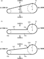
図8(a)に例示するように、従来のラリンジアルマスクは、環状カフ50が、人体側面視で先端部(反口腔J2側)が細いクサビ形である。そのため、挿入位置に挿入した環状カフ50を膨張させたとき、その反力Fが人体前側から環状カフ50に作用するが、クサビ形の傾斜面に作用する反力Fは、環状カフ50を人体後方へ押圧する分力成分F1と、口腔J2側へ押し戻そうとする分力成分F2とを持つことになる。その結果、後者の口腔J2側へ押し戻そうとする分力成分F2の存在により、環状カフ50を膨張させたとき、環状カフ50が挿入位置から抜けるという不具合が生じる。
これに対し、図8(b)に例示するように、本実施形態に係るラリンジアルマスク1では、環状カフ50は、挿入位置に挿入された状態で、口腔J2側のカフ基端部50Rと、このカフ基端部50Rよりも反口腔J2側のカフ先端部50Fとを備えている。そして、環状カフ50が膨張した状態で、カフ基端部50Rはカフ先端部50Fよりも人体側面視で厚みが大きく、かつ、カフ基端部50Rとカフ先端部50F(より詳しくはカフ中間側部50b)との間に人体側面視で人体前側に段差50xが形成されている。つまり、段差50xの存在により、カフ基端部50Rがカフ先端部50Fよりも前方に突出し、カフ基端部50Rの人体前側の面とカフ先端部50Fの人体前側の面とは互いに不連続となる。そのため、図8(a)に示したような環状カフ50の後部と前部とを連続してつなぐ傾斜面が形成されず、環状カフ50が膨張したときに作用する人体前側からの反力Fは、主として、厚みの大きいカフ基端部50Rに作用する。つまり、膨張に対する反力Fは、カフ基端部50Rに作用する割合が多く、カフ先端部50Fに作用する割合が少なくなる。その結果、カフ先端部50Fに作用する反力が少ないから、環状カフ50を口腔J2側へ押し戻そうとする分力成分の発生が抑えられ、環状カフ50を膨張させたときに環状カフ50が挿入位置から抜けるという不具合が抑制される。
加えて、舌J9の奥部と喉頭蓋J3との間には喉頭蓋谷J10が形成されている。環状カフ50が膨張したとき、カフ基端部50Rは舌J9の奥部と喉頭蓋J3との間に位置して喉頭蓋谷J10に潜り込もうとする。ここで、図8(a)のように段差が形成されていないと、環状カフ50の後部と前部とを連続してつなぐクサビ形の傾斜面が邪魔になって、カフ基端部50Rは喉頭蓋谷J10に潜り込み難くなるのに対し、図8(b)のように段差50xが形成されていると、その段差50xの存在により、カフ基端部50Rがカフ先端部50Fよりも前方に突出しているので、カフ基端部50Rの喉頭蓋谷J10への潜り込みが阻害されず促進される。そして、環状カフ50が膨張して、カフ基端部50Rが喉頭蓋谷J10に潜り込んだ状態では、カフ基端部50Rには、カフ基端部50Rを人体後方(背側)へ押圧しようとする反力が舌J9の奥部から作用する。そのとき、舌J9の奥部がカフ基端部50Rよりも口腔J2側にあるため、前記反力は、環状カフ50を反口腔J2側、すなわち挿入方向へ向かわせる分力成分を持つ。以上により、環状カフ50を膨張させたとき、ラリンジアルマスク1はより一層抜け難くなる。
以上により、本実施形態によれば、挿入位置に挿入した環状カフ50を膨張させたときに環状カフ50が挿入位置から抜けることが抑制されるラリンジアルマスク1が提供される。
[3-2]
本実施形態では、環状カフ50が膨張した状態で、カフ基端部50Rは、人体前方に膨張して咽頭Tの人体前側の組織と密着可能であり、カフ先端部50F(より詳しくは一対のカフ中間側部50b)は、人体左方及び右方に膨張して咽頭Tの人体左側及び右側の組織と密着可能な側面(カフ側面)50zを有する。
本実施形態では、環状カフ50が膨張した状態で、カフ基端部50Rは、人体前方に膨張して咽頭Tの人体前側の組織と密着可能であり、カフ先端部50F(より詳しくは一対のカフ中間側部50b)は、人体左方及び右方に膨張して咽頭Tの人体左側及び右側の組織と密着可能な側面(カフ側面)50zを有する。
この構成によれば、相対的に厚みの大きいカフ基端部50Rは咽頭Tの人体前側の組織と密着するのに対し、相対的に厚みの小さいカフ先端部50Fは咽頭Tの人体左側及び右側の組織と密着する。そのため、カフ先端部50Fが人体前側の組織と密着しなくても、人体左側及び右側の組織とカフ側面50zで密着することにより、食道J5と気管J6との連通が良好に遮断される。また、カフ基端部50Rとカフ先端部50Fとが互いに異なる2方向で人体の組織と密着するので、環状カフ50が咽頭T内でしっかりと確実に固定される。
加えて、カフ先端部50F(より詳しくはそのカフ中間側部50b)の人体前方への膨張が抑制されることにより、カフ中間側部50bに作用する人体前側から膨張の反力の割合がより一層少なくなる。しかも、本実施形態では、カフ中間側部50bの人体前側の面は、支持部材12と平行に(人体の前後方向に平行に)形成されており、クサビ形の傾斜面には形成されていない。その結果、環状カフ50を膨張させたときに、環状カフ50を口腔J2側へ押し戻そうとする分力成分がほとんど発生せず、環状カフ50が挿入位置から抜けるという不具合が大幅に抑制される。
[3-3]
本実施形態では、環状カフ50が膨張した状態で、人体左側及び右側の組織と密着するカフ先端部50F(より詳しくはそのカフ中間側部50b)の側面(カフ側面)50zは、上下方向及び前後方向に平坦状に形成されている。
本実施形態では、環状カフ50が膨張した状態で、人体左側及び右側の組織と密着するカフ先端部50F(より詳しくはそのカフ中間側部50b)の側面(カフ側面)50zは、上下方向及び前後方向に平坦状に形成されている。
この構成によれば、カフ先端部50Fの側面が例えば上下方向に円弧状に形成されている場合と比べて、カフ先端部50Fが人体左側及び右側の組織と密着する際の接触面積が増大するので、環状カフ50がより一層咽頭T内でしっかりと確実に固定され、食道J5と気管J6との連通がさらに良好に遮断される。
[3-4]
本実施形態では、カフ先端部50F(より詳しくはそのカフ中間側部50b)を環状カフ50の内方から支持する支持部材12が備えられている。より詳しくは、この支持部材12は、カフ先端部50Fが人体左方及び右方に膨張したときにカフ先端部50Fに作用する人体左側及び右側からの反力に対してカフ先端部50Fを支持する。言い換えると、側方からの外力に対するカフ先端部50Fの変形を抑えるように、カフ先端部50Fを環状カフ50の内方から支持する支持部材12が備えられている。
本実施形態では、カフ先端部50F(より詳しくはそのカフ中間側部50b)を環状カフ50の内方から支持する支持部材12が備えられている。より詳しくは、この支持部材12は、カフ先端部50Fが人体左方及び右方に膨張したときにカフ先端部50Fに作用する人体左側及び右側からの反力に対してカフ先端部50Fを支持する。言い換えると、側方からの外力に対するカフ先端部50Fの変形を抑えるように、カフ先端部50Fを環状カフ50の内方から支持する支持部材12が備えられている。
この構成によれば、例えば、カフ先端部50Fが人体左方及び右方に膨張し、カフ先端部50Fに人体左側及び右側から膨張の反力が作用したときに、カフ先端部50Fの変形が抑えられる。そのため、カフ先端部50Fが人体左側及び右側の組織とより一層確実に密着する。
[3-5]
本実施形態では、支持部材12よりも人体左方及び右方に突出し、環状カフ50が挿入位置に挿入された状態で、咽頭T内で咽頭Tの組織を介して舌骨J7に当接する舌骨当接部13が備えられている。
本実施形態では、支持部材12よりも人体左方及び右方に突出し、環状カフ50が挿入位置に挿入された状態で、咽頭T内で咽頭Tの組織を介して舌骨J7に当接する舌骨当接部13が備えられている。
舌骨J7は、気管J6の開口部の周囲の組織と靭帯で結合されているため、気管J6の開口部に対して位置ズレが少ない。そのため、舌骨J7の位置に基づいて環状カフ50の挿入位置を設定すれば、環状カフ50を正確に気管J6の開口部の周囲の組織に密着させることができる。したがって、この構成によれば、支持部材12よりも人体左方及び右方に突出する舌骨当接部13が咽頭T内で咽頭Tの組織を介して舌骨J7に当接することにより、環状カフ50が正確に挿入位置で停止されて位置決めされる。そのため、環状カフ50は位置ズレせずに正確に気管J6の開口部の周囲の組織に密着する。
[3-6]
本実施形態では、環状カフ50が膨張した状態で、カフ基端部50Rの前面(ラリンジアルマスク単品についての前面)に窪み部50eが形成され、これにより、喉頭蓋J3を収容可能なスペースが提供されている。また、環状カフ50が膨張した状態で、カフ基端部50Rの後面(ラリンジアルマスク単品についての後面)と挿入チューブ11との間に舌J9を収容可能なスペース50gが形成されている(図2および図7参照)。そのため、カフ基端部50Rが舌J9の奥部と喉頭蓋J3との間に確実に位置し、潜り込んでいる。
本実施形態では、環状カフ50が膨張した状態で、カフ基端部50Rの前面(ラリンジアルマスク単品についての前面)に窪み部50eが形成され、これにより、喉頭蓋J3を収容可能なスペースが提供されている。また、環状カフ50が膨張した状態で、カフ基端部50Rの後面(ラリンジアルマスク単品についての後面)と挿入チューブ11との間に舌J9を収容可能なスペース50gが形成されている(図2および図7参照)。そのため、カフ基端部50Rが舌J9の奥部と喉頭蓋J3との間に確実に位置し、潜り込んでいる。
この構成によれば、環状カフ50が膨張したとき、カフ基端部50Rは舌J9の奥部と喉頭蓋J3との間に確実に位置する。そのため、環状カフ50を膨張させたとき、カフ基端部50Rは喉頭蓋谷J10に確実に潜り込み、その結果、ラリンジアルマスク1はより一層確実に抜け難くなる。
[3-7]
以上に加えて、本実施形態では、挿入チューブ11の先端部の構成に関し、次のような作用がある。
以上に加えて、本実施形態では、挿入チューブ11の先端部の構成に関し、次のような作用がある。
挿入チューブ11の先端部のチューブ円弧終了位置Xを上方(人体前方側)に配置し、チューブ円弧終了位置Xの直ぐ後側の部分を上り傾斜に形成し、この上り傾斜の先に、メイン空気排出口11cが位置し、さらにその先に、気管J6の開口部が位置するように設定したから、図7に矢印Yで示したように、人工呼吸器から供給された空気がメイン空気排出口11cを介して効果的に気管J6に送り込まれる。また、このラリンジアルマスク1を通して気管挿管を行う際には、挿入チューブ11の内部を挿通してきた気管チューブの先端部がメイン空気排出口11cを介して良好に気管J6に挿通され、ラリンジアルマスク1を通しての気管挿管が容易となる。
同様に、挿入チューブ11の先端部のチューブ円弧終了位置Xを上方(人体前方側)に配置し、チューブ円弧終了位置Xに配置した舌骨当接部13を上方(人体前方側)に配置したから、図6に示したように、舌骨当接部13が、咽頭Tを人体Jの前側及び左右両側から囲むU字状を呈している舌骨J7に当接し易くなり、確実に環状カフ50を舌骨J7で停止させて位置決めすることができる。
挿入チューブ11の先端部は、全面開口とせず、最終部分11xにスロープ状の天井壁11aを設け、この天井壁11aの一部に小さめの空気排出口11c,11d,11eを複数形成したから、挿入チューブ11の挿入中に喉頭蓋J3の先端が空気排出口に引っ掛かったり落ち込んだりすることが抑制される。そのため、喉頭蓋J3による挿入チューブ11ないし気道の閉塞が抑制される。これに対し、挿入チューブ11の先端部が全面開口していると、挿入チューブ11の挿入中に喉頭蓋J3の先端が開口に引っ掛かったり落ち込んだりして、挿入チューブ11ないし気道が喉頭蓋J3によって閉塞されるという問題が発生するのである。また、メイン空気排出口11cが縦(前後方向)に長いことも、喉頭蓋J3によるメイン空気排出口11cの閉塞が抑制される要因の一つである。
挿入チューブ11の最終部分11xは、天井壁11aだけでなく、左右の側壁11bにも空気排出口11fを形成したから、挿入チューブ11の気道抵抗が減少する。そのため、少ない圧力(エネルギー)で良好に空気を気管J6ないし肺に送り込むことができる。
[3-8]
また、本実施形態では、環状カフ50の構成に関し、次のような作用がある。
また、本実施形態では、環状カフ50の構成に関し、次のような作用がある。
図7に示したように、環状カフ50が挿入位置に挿入され、膨張した状態で、喉頭蓋J3がカフ基端部50Rの窪み部(喉頭蓋J3の収容スペース)50eに嵌まり込んで収容されるので、これによっても、喉頭蓋J3が気道の妨げになることが抑制される。
従来は尖っていた環状カフ50の先頭部50aを丸みを持たせて左右に拡幅した。さらに、拡幅したカフ先頭部50aの左右の側縁部を上方に持ち上げて反らせる形状、すなわち、正面視で上向きに凹むように緩やかに湾曲する円弧状とした。一方、人体Jの気管J6の入口は細く、食道J5の入口は左右に長い形状である。そのため、環状カフ50は食道J5に向かって入り易くなり、誤って気管J6に入ることが効果的に未然防止される。
前記のように、従来、環状カフは側面視でクサビ形であることに加えて、平面視でも先端部が細く尖った形状であった。その結果、人体前側からの膨張の反力だけでなく、人体側方(左右方向)からの膨張の反力によっても、環状カフを口腔J2側へ押し戻そうとする分力成分が発生する。これに対し、本実施形態では、図4に示したように、環状カフ50の先頭部50aを左右に拡幅し、環状カフ50を平面視で略矩形状に形成することにより、人体前側からの反力だけでなく人体側方からの反力に対しても、抜け方向の分力成分の発生を抑制することができる。
挿入時は、環状カフ50は収縮しているので、喉頭蓋J3が環状カフ50に引っ掛かることが抑制される。
[3-9]
また、本実施形態では、第1コネクタ30の構成に関し、次のような作用がある。
また、本実施形態では、第1コネクタ30の構成に関し、次のような作用がある。
図3に示したように、第1コネクタ30が挿入チューブ11に連結された状態で、左右一対の板状突片32が挿入チューブ11の上端部で左右に突出する。この板状突片32により、患者の下顎を持ち上げながらラリンジアルマスク1を挿入することが容易にできる。つまり、ラリンジアルマスク1を患者の口腔J2から挿入する際は、患者の下顎を持ち上げて、咽頭Tから食道J5や気管J6を広げると挿入し易い。この板状突片32があることにより、この板状突片32に両手の親指を掛け、他の4本の指で下顎を持ち上げながら板状突片32を押し込むということが容易に行え、ラリンジアルマスク1の挿入が良好に行える。
(4)使用例
環状カフがクサビ形の従来のラリンジアルマスクを患者に対して使用したところ、環状カフの前側の面(上面)が環状カフの基端部と先端部とを連続してつなぐ傾斜面なので、膨張した環状カフには、挿入位置から抜ける方向の力が作用した。
環状カフがクサビ形の従来のラリンジアルマスクを患者に対して使用したところ、環状カフの前側の面(上面)が環状カフの基端部と先端部とを連続してつなぐ傾斜面なので、膨張した環状カフには、挿入位置から抜ける方向の力が作用した。
これに対し、本発明に係るラリンジアルマスクを患者に対して使用したところ、環状カフの基端部と先端部との間に段差があり、基端部と先端部との間に大きな高さの落差が生成し、厚みの大きい基端部にのみ反力が作用するので、膨張した環状カフには挿入位置から抜ける方向の力が作用しなかった。代わりに、カフ基端部が舌の奥部と喉頭蓋との間の喉頭蓋谷に潜り込むので、膨張した環状カフには、反口腔側へ向かう力、すなわち挿入方向の力が作用した。
そのときの状態を人体尾側からX線撮像したところ、カフ先端部のカフ中間側部が人体左方及び右方に膨張して咽頭の人体左側及び右側の組織と密着していることが確認された。また、支持部材の左右の側縁部がカフ中間側部を環状カフの内方から支持しているので、カフ中間側部が膨張したときにカフ中間側部が環状カフの内方に後退することが規制され、カフ中間側部が人体左側及び右側の組織と確実に密着していることも確認された。
さらに、本発明に係るラリンジアルマスクを別の患者に対して使用したときの状態を人体側面からX線撮像した。喉頭蓋がカフ基端部の窪み部に収容されているので、挿入チューブの最終部分に形成された空気排出口、及び気管の開口部が喉頭蓋で塞がれていないこと、つまり、喉頭蓋が気道確保の妨げになっていないことが確認された。
また、そのときの状態を人体腹側からX線撮像した。舌骨当接部が支持部材よりも人体左方及び右方に突出し、咽頭内で咽頭の組織を介して舌骨に口腔側から当接していることが確認された。また、カフ先端部のカフ中間側部が人体左方及び右方に膨張して咽頭の人体左側及び右側の組織と密着していることも確認された。
(5)他の実施形態
前記実施形態では、図8(b)に示したように、環状カフ50が膨張した状態で、カフ中間側部50bの上面(人体挿入時に人体前方を向く面)は、支持部材12と平行に(人体の前後方向に平行に)形成されており、クサビ形の傾斜面ではなかったが、これに代えて、カフ基端部50Rはカフ先端部50Fよりも人体側面視で厚みが大きく、かつ、カフ基端部50Rとカフ先端部50Fとの間に人体側面視で人体前側に段差50xが形成されている限り、図8(c)に示すように、カフ中間側部50bの上面は、クサビ形の傾斜面であっても構わない。このような態様によっても、段差50xの存在により、環状カフ50が膨張したときに作用する人体前側からの反力Fは、主として、厚みの大きいカフ基端部50Rに作用し、その結果、環状カフ50を口腔J2側へ押し戻そうとする分力成分の発生が抑えられ、環状カフ50の膨張時に環状カフ50が挿入位置から抜けるという不具合が抑制される。
前記実施形態では、図8(b)に示したように、環状カフ50が膨張した状態で、カフ中間側部50bの上面(人体挿入時に人体前方を向く面)は、支持部材12と平行に(人体の前後方向に平行に)形成されており、クサビ形の傾斜面ではなかったが、これに代えて、カフ基端部50Rはカフ先端部50Fよりも人体側面視で厚みが大きく、かつ、カフ基端部50Rとカフ先端部50Fとの間に人体側面視で人体前側に段差50xが形成されている限り、図8(c)に示すように、カフ中間側部50bの上面は、クサビ形の傾斜面であっても構わない。このような態様によっても、段差50xの存在により、環状カフ50が膨張したときに作用する人体前側からの反力Fは、主として、厚みの大きいカフ基端部50Rに作用し、その結果、環状カフ50を口腔J2側へ押し戻そうとする分力成分の発生が抑えられ、環状カフ50の膨張時に環状カフ50が挿入位置から抜けるという不具合が抑制される。
また、カフ先端部50Fが人体前方に膨張しないことにより、たとえカフ先端部50Fがクサビ形の傾斜面を持っていたとしても、そのクサビ形の傾斜面に人体前側から膨張の反力が作用することが抑制される。その結果、環状カフ50を口腔J2側へ押し戻そうとする分力成分の発生が抑えられて、環状カフ50が挿入位置から抜けるという不具合が大幅に抑制されるという作用も維持される。
前記実施形態では、挿入チューブ11と、支持部材12と、左右一対の舌骨当接部13とが一体成型されていたが、これに限らず、別々に成形して後で接合してもよい。
前記実施形態に係るラリンジアルマスク1に、患者の咽頭Tを冷却するための冷却装置を具備してもよい。
以上のように、本明細書は、本発明の様々な態様を開示する。それらのうちの主なものを以下にまとめる。
本発明は、人体の食道と気管との連通を遮断しつつ気道を確保するためのラリンジアルマスクであって、前記気管に連通するように人体に挿入される挿入チューブと、前記挿入チューブの先端部に設けられ、口腔から予め設定された挿入位置に挿入された状態で膨張することにより前記気管の開口部の周囲の組織に密着可能な環状カフとを有し、前記環状カフが、カフ基端部と、その先端に設けられたカフ先端部とを備え、前記環状カフが膨張した状態で、前記カフ基端部は前記カフ先端部よりも側面視で厚みが大きく、かつ、前記カフ基端部と前記カフ先端部とは側面視でカフ基端部がカフ先端部よりも前方に突出して段差が形成されるように互いに連結されている、ラリンジアルマスクである。
本発明によれば、膨張した環状カフにおいては、カフ基端部がカフ先端部よりも前方に突出しているので、膨張に対する反力は、カフ基端部に作用する割合が多く、カフ先端部に作用する割合が少なくなる。そのため、たとえカフ先端部の前方側の面が傾斜面であっても、カフ先端部に作用する反力が少ないから、環状カフを口腔側へ押し戻そうとする分力が小さくなる。これにより、環状カフを膨張させたときに環状カフが挿入位置から抜けるという不具合が抑制される。
加えて、図9を参照して説明したように、舌J9の奥部と喉頭蓋J3との間には喉頭蓋谷J10が形成されている。環状カフが膨張したとき、カフ基端部は舌J9の奥部と喉頭蓋J3との間に位置して喉頭蓋谷J10に潜り込もうとする。ここで、環状カフに本発明のような段差が形成されていないと、カフ基端部は喉頭蓋谷に潜り込み難くなるのに対し、本発明によれば、前記段差の存在により、カフ基端部がカフ先端部よりも前方に突出しているので、カフ基端部の喉頭蓋谷への潜り込みが阻害されず促進される。そして、環状カフが膨張して、カフ基端部が喉頭蓋谷に潜り込んだ状態では、カフ基端部には、カフ基端部を人体後方(背側)へ押圧しようとする反力が舌の奥部から作用する。そのとき、舌の奥部がカフ基端部よりも口腔側にあるため、前記反力は、環状カフを反口腔側、すなわち挿入方向へ向かわせる分力成分を持つ。以上により、環状カフを膨張させたとき、ラリンジアルマスクはより一層抜け難くなる。
以上により、本発明によれば、挿入位置に挿入した環状カフを膨張させたときに環状カフが挿入位置から抜けることが抑制されるラリンジアルマスクが提供される。
本発明においては、前記環状カフが膨張した状態で、前記カフ基端部は前方に膨張して咽頭の人体前側の組織と密着可能であり、前記カフ先端部は側方に膨張して咽頭の人体左側及び右側の組織と密着可能な側面を有することが好ましい。
この構成によれば、カフ先端部が人体前側の組織と密着しなくても、人体左側及び右側の組織と側面で密着することにより、食道と気管との連通が良好に遮断される。また、カフ基端部が人体前側の組織と密着し、カフ先端部がそれと異なる方向の人体左側及び右側の組織と密着するので、環状カフが咽頭内でしっかりと確実に固定される。
加えて、カフ先端部の前方への膨張が抑制されることにより、カフ先端部に作用する反力の割合がより一層少なくなる。そのため、たとえカフ先端部の前方側の面が傾斜面であっても、環状カフを口腔側へ押し戻そうとする分力がさらに小さくなる。これにより、環状カフを膨張させたときに環状カフが挿入位置から抜けるという不具合がより一層抑制される。
本発明においては、前記環状カフが膨張した状態で、前記カフ先端部の側面は上下方向及び前後方向に平坦状に形成されていることが好ましい。
この構成によれば、カフ先端部の側面が例えば上下方向に円弧状に形成されている場合と比べて、カフ先端部が人体左側及び右側の組織と密着する際の接触面積が増大するので、環状カフがより一層咽頭内でしっかりと確実に固定され、食道と気管との連通がさらに良好に遮断される。
本発明においては、側方からの外力に対する前記カフ先端部の変形を抑えるように前記カフ先端部を前記環状カフの内方から支持する支持部材が備えられていることが好ましい。
この構成によれば、例えば、カフ先端部が側方に膨張し、カフ先端部に人体左側及び右側から膨張の反力が作用したときに、カフ先端部の変形が抑えられるので、カフ先端部が人体左側及び右側の組織とより一層確実に密着する。
本発明においては、前記支持部材よりも側方に突出し、前記環状カフが前記挿入位置に挿入された状態で、咽頭内で咽頭の組織を介して舌骨に当接する舌骨当接部が備えられていることが好ましい。
図9を参照して説明したように、舌骨J7は、気管J6の開口部の周囲の組織と靭帯で結合されているため、気管J6の開口部に対して位置ズレが少ない。そのため、舌骨J7の位置に基づいて環状カフの挿入位置を設定すれば、環状カフを正確に気管J6の開口部の周囲の組織に密着させることができる。したがって、この構成によれば、支持部材よりも側方に突出する舌骨当接部が咽頭内で咽頭の組織を介して舌骨に当接することにより、環状カフが正確に挿入位置で停止されて位置決めされるので、環状カフは位置ズレせずに正確に気管の開口部の周囲の組織に密着する。
本発明においては、前記環状カフが膨張した状態で、前記カフ基端部の前面に喉頭蓋を収容可能なスペースが形成され、前記カフ基端部の後面と前記挿入チューブとの間に舌を収容可能なスペースが形成されることが好ましい。
この構成によれば、環状カフが膨張したとき、カフ基端部は舌の奥部と喉頭蓋との間に確実に位置する。そのため、環状カフを膨張させたとき、カフ基端部は喉頭蓋谷に確実に潜り込み、その結果、前述したようにラリンジアルマスクがより一層抜け難くなることが確実となる。
Claims (6)
- 人体の食道と気管との連通を遮断しつつ気道を確保するためのラリンジアルマスクであって、
前記気管に連通するように人体に挿入される挿入チューブと、
前記挿入チューブの先端部に設けられ、口腔から予め設定された挿入位置に挿入された状態で膨張することにより前記気管の開口部の周囲の組織に密着可能な環状カフとを有し、
前記環状カフが、カフ基端部と、その先端に設けられたカフ先端部とを備え、
前記環状カフが膨張した状態で、前記カフ基端部は前記カフ先端部よりも側面視で厚みが大きく、かつ、前記カフ基端部と前記カフ先端部とは側面視でカフ基端部がカフ先端部よりも前方に突出して段差が形成されるように互いに連結されている、ラリンジアルマスク。 - 前記環状カフが膨張した状態で、前記カフ基端部は前方に膨張して咽頭の人体前側の組織と密着可能であり、前記カフ先端部は側方に膨張して咽頭の人体左側及び右側の組織と密着可能な側面を有する、請求項1に記載のラリンジアルマスク。
- 前記環状カフが膨張した状態で、前記カフ先端部の側面は上下方向及び前後方向に平坦状に形成されている、請求項2に記載のラリンジアルマスク。
- 側方からの外力に対する前記カフ先端部の変形を抑えるように前記カフ先端部を前記環状カフの内方から支持する支持部材が備えられている、請求項1から3のいずれか1項に記載のラリンジアルマスク。
- 前記支持部材よりも側方に突出し、前記環状カフが前記挿入位置に挿入された状態で、咽頭内で咽頭の組織を介して舌骨に当接する舌骨当接部が備えられている、請求項4に記載のラリンジアルマスク。
- 前記環状カフが膨張した状態で、前記カフ基端部の前面に喉頭蓋を収容可能なスペースが形成され、前記カフ基端部の後面と前記挿入チューブとの間に舌を収容可能なスペースが形成される、請求項1から5のいずれか1項に記載のラリンジアルマスク。
Applications Claiming Priority (2)
| Application Number | Priority Date | Filing Date | Title |
|---|---|---|---|
| JP2014-016675 | 2014-01-31 | ||
| JP2014016675A JP6378886B2 (ja) | 2014-01-31 | 2014-01-31 | ラリンジアルマスク |
Publications (1)
| Publication Number | Publication Date |
|---|---|
| WO2015115383A1 true WO2015115383A1 (ja) | 2015-08-06 |
Family
ID=53756956
Family Applications (1)
| Application Number | Title | Priority Date | Filing Date |
|---|---|---|---|
| PCT/JP2015/052077 Ceased WO2015115383A1 (ja) | 2014-01-31 | 2015-01-26 | ラリンジアルマスク |
Country Status (2)
| Country | Link |
|---|---|
| JP (1) | JP6378886B2 (ja) |
| WO (1) | WO2015115383A1 (ja) |
Citations (7)
| Publication number | Priority date | Publication date | Assignee | Title |
|---|---|---|---|---|
| JPH11206885A (ja) * | 1997-12-02 | 1999-08-03 | Smiths Ind Plc | 喉頭部マスク組立体 |
| JP2005502384A (ja) * | 2000-07-15 | 2005-01-27 | ミラー,ドナルド,ムンロー | 呼吸装置の改良および同装置に関する改良 |
| US20060032505A1 (en) * | 2004-08-13 | 2006-02-16 | Engineered Medical Systems, Inc. | Perilaryngeal oral airway with multi-lumen esophogeal-obturator |
| JP2007514496A (ja) * | 2003-12-18 | 2007-06-07 | イデアメド・エヌ・ブイ | 収縮領域付きのカフを有する呼吸チューブ |
| JP2008541817A (ja) * | 2005-05-27 | 2008-11-27 | ザ ラリンジアル マスク カンパニー リミテッド | 喉頭マスク気道装置 |
| WO2012164868A1 (ja) * | 2011-05-31 | 2012-12-06 | 国立大学法人岡山大学 | ラリンジアルマスク |
| US20140014114A1 (en) * | 2011-03-22 | 2014-01-16 | Donald Munro Miller | Laryngeal mask airway |
Family Cites Families (2)
| Publication number | Priority date | Publication date | Assignee | Title |
|---|---|---|---|---|
| US20090090356A1 (en) * | 2007-10-03 | 2009-04-09 | Cook Daniel J | Supralaryngeal Airway Including Instrument Ramp |
| US20090277447A1 (en) * | 2008-05-12 | 2009-11-12 | Advanced Circulatory Systems, Inc. | System, method, and device to increase circulation during cpr without requiring positive pressure ventilation |
-
2014
- 2014-01-31 JP JP2014016675A patent/JP6378886B2/ja active Active
-
2015
- 2015-01-26 WO PCT/JP2015/052077 patent/WO2015115383A1/ja not_active Ceased
Patent Citations (7)
| Publication number | Priority date | Publication date | Assignee | Title |
|---|---|---|---|---|
| JPH11206885A (ja) * | 1997-12-02 | 1999-08-03 | Smiths Ind Plc | 喉頭部マスク組立体 |
| JP2005502384A (ja) * | 2000-07-15 | 2005-01-27 | ミラー,ドナルド,ムンロー | 呼吸装置の改良および同装置に関する改良 |
| JP2007514496A (ja) * | 2003-12-18 | 2007-06-07 | イデアメド・エヌ・ブイ | 収縮領域付きのカフを有する呼吸チューブ |
| US20060032505A1 (en) * | 2004-08-13 | 2006-02-16 | Engineered Medical Systems, Inc. | Perilaryngeal oral airway with multi-lumen esophogeal-obturator |
| JP2008541817A (ja) * | 2005-05-27 | 2008-11-27 | ザ ラリンジアル マスク カンパニー リミテッド | 喉頭マスク気道装置 |
| US20140014114A1 (en) * | 2011-03-22 | 2014-01-16 | Donald Munro Miller | Laryngeal mask airway |
| WO2012164868A1 (ja) * | 2011-05-31 | 2012-12-06 | 国立大学法人岡山大学 | ラリンジアルマスク |
Also Published As
| Publication number | Publication date |
|---|---|
| JP6378886B2 (ja) | 2018-08-22 |
| JP2015142634A (ja) | 2015-08-06 |
Similar Documents
| Publication | Publication Date | Title |
|---|---|---|
| JP6033772B2 (ja) | ラリンジアルマスク | |
| JP6585209B2 (ja) | 人工気道装置 | |
| CN103189090B (zh) | 人工气道装置 | |
| JP5089579B2 (ja) | 喉頭マスク気道装置 | |
| US7900632B2 (en) | Laryngeal mask with esophageal blocker and bite block | |
| CN103442762A (zh) | 喉罩和气管导管导气管装置 | |
| WO2008001724A1 (en) | Laryngeal mask provided with gastric tube insertion guide | |
| MXPA06001317A (es) | Mascara laringea. | |
| TWI687243B (zh) | 人造氣道裝置 | |
| KR101789171B1 (ko) | 기도유지 및 삽관 가이드장치 | |
| KR20160144972A (ko) | 기도 관리 장치 및 제조 방법 | |
| JP2000152995A (ja) | 薄型人工気道装置 | |
| US20140014114A1 (en) | Laryngeal mask airway | |
| US9038627B2 (en) | Artificial oral airway, esophageal blocker, and pharyngeal airway assembly | |
| JP6378886B2 (ja) | ラリンジアルマスク | |
| JP2019509860A (ja) | ラリンジアルマスク用固定装置 | |
| JP2021122491A (ja) | ラリンジアルマスク | |
| JPWO2007061076A1 (ja) | 気道確保具 |
Legal Events
| Date | Code | Title | Description |
|---|---|---|---|
| 121 | Ep: the epo has been informed by wipo that ep was designated in this application |
Ref document number: 15744007 Country of ref document: EP Kind code of ref document: A1 |
|
| NENP | Non-entry into the national phase |
Ref country code: DE |
|
| 122 | Ep: pct application non-entry in european phase |
Ref document number: 15744007 Country of ref document: EP Kind code of ref document: A1 |