WO2015115188A1 - ヘキサフルオロマンガン(iv)酸塩及び複フッ化物蛍光体並びにそれらの製造方法 - Google Patents
ヘキサフルオロマンガン(iv)酸塩及び複フッ化物蛍光体並びにそれらの製造方法 Download PDFInfo
- Publication number
- WO2015115188A1 WO2015115188A1 PCT/JP2015/050906 JP2015050906W WO2015115188A1 WO 2015115188 A1 WO2015115188 A1 WO 2015115188A1 JP 2015050906 W JP2015050906 W JP 2015050906W WO 2015115188 A1 WO2015115188 A1 WO 2015115188A1
- Authority
- WO
- WIPO (PCT)
- Prior art keywords
- chamber
- manganese
- hydrogen fluoride
- reaction
- solution
- Prior art date
- Legal status (The legal status is an assumption and is not a legal conclusion. Google has not performed a legal analysis and makes no representation as to the accuracy of the status listed.)
- Ceased
Links
Images


Classifications
-
- C—CHEMISTRY; METALLURGY
- C09—DYES; PAINTS; POLISHES; NATURAL RESINS; ADHESIVES; COMPOSITIONS NOT OTHERWISE PROVIDED FOR; APPLICATIONS OF MATERIALS NOT OTHERWISE PROVIDED FOR
- C09K—MATERIALS FOR MISCELLANEOUS APPLICATIONS, NOT PROVIDED FOR ELSEWHERE
- C09K11/00—Luminescent materials, e.g. electroluminescent or chemiluminescent
- C09K11/08—Luminescent materials, e.g. electroluminescent or chemiluminescent containing inorganic luminescent materials
- C09K11/67—Luminescent materials, e.g. electroluminescent or chemiluminescent containing inorganic luminescent materials containing refractory metals
- C09K11/674—Halogenides
- C09K11/675—Halogenides with alkali or alkaline earth metals
-
- B—PERFORMING OPERATIONS; TRANSPORTING
- B01—PHYSICAL OR CHEMICAL PROCESSES OR APPARATUS IN GENERAL
- B01J—CHEMICAL OR PHYSICAL PROCESSES, e.g. CATALYSIS OR COLLOID CHEMISTRY; THEIR RELEVANT APPARATUS
- B01J19/00—Chemical, physical or physico-chemical processes in general; Their relevant apparatus
- B01J19/08—Processes employing the direct application of electric or wave energy, or particle radiation; Apparatus therefor
- B01J19/087—Processes employing the direct application of electric or wave energy, or particle radiation; Apparatus therefor employing electric or magnetic energy
- B01J19/088—Processes employing the direct application of electric or wave energy, or particle radiation; Apparatus therefor employing electric or magnetic energy giving rise to electric discharges
-
- C—CHEMISTRY; METALLURGY
- C01—INORGANIC CHEMISTRY
- C01B—NON-METALLIC ELEMENTS; COMPOUNDS THEREOF; METALLOIDS OR COMPOUNDS THEREOF NOT COVERED BY SUBCLASS C01C
- C01B33/00—Silicon; Compounds thereof
- C01B33/08—Compounds containing halogen
- C01B33/10—Compounds containing silicon, fluorine, and other elements
-
- C—CHEMISTRY; METALLURGY
- C01—INORGANIC CHEMISTRY
- C01G—COMPOUNDS CONTAINING METALS NOT COVERED BY SUBCLASSES C01D OR C01F
- C01G17/00—Compounds of germanium
- C01G17/006—Compounds containing germanium, with or without oxygen or hydrogen, and containing two or more other elements
-
- C—CHEMISTRY; METALLURGY
- C01—INORGANIC CHEMISTRY
- C01G—COMPOUNDS CONTAINING METALS NOT COVERED BY SUBCLASSES C01D OR C01F
- C01G19/00—Compounds of tin
- C01G19/006—Compounds containing tin, with or without oxygen or hydrogen, and containing two or more other elements
-
- C—CHEMISTRY; METALLURGY
- C01—INORGANIC CHEMISTRY
- C01G—COMPOUNDS CONTAINING METALS NOT COVERED BY SUBCLASSES C01D OR C01F
- C01G23/00—Compounds of titanium
- C01G23/002—Compounds containing titanium, with or without oxygen or hydrogen, and containing two or more other elements
-
- C—CHEMISTRY; METALLURGY
- C01—INORGANIC CHEMISTRY
- C01G—COMPOUNDS CONTAINING METALS NOT COVERED BY SUBCLASSES C01D OR C01F
- C01G25/00—Compounds of zirconium
- C01G25/006—Compounds containing zirconium, with or without oxygen or hydrogen, and containing two or more other elements
-
- C—CHEMISTRY; METALLURGY
- C01—INORGANIC CHEMISTRY
- C01G—COMPOUNDS CONTAINING METALS NOT COVERED BY SUBCLASSES C01D OR C01F
- C01G27/00—Compounds of hafnium
- C01G27/006—Compounds containing hafnium, with or without oxygen or hydrogen, and containing two or more other elements
-
- C—CHEMISTRY; METALLURGY
- C01—INORGANIC CHEMISTRY
- C01G—COMPOUNDS CONTAINING METALS NOT COVERED BY SUBCLASSES C01D OR C01F
- C01G45/00—Compounds of manganese
- C01G45/06—Halides; Oxyhalides
-
- C—CHEMISTRY; METALLURGY
- C01—INORGANIC CHEMISTRY
- C01G—COMPOUNDS CONTAINING METALS NOT COVERED BY SUBCLASSES C01D OR C01F
- C01G45/00—Compounds of manganese
- C01G45/12—Complex oxides containing manganese and at least one other metal element
- C01G45/1221—Manganates or manganites with trivalent manganese, tetravalent manganese or mixtures thereof
-
- C—CHEMISTRY; METALLURGY
- C01—INORGANIC CHEMISTRY
- C01G—COMPOUNDS CONTAINING METALS NOT COVERED BY SUBCLASSES C01D OR C01F
- C01G45/00—Compounds of manganese
- C01G45/20—Compounds containing manganese, with or without oxygen or hydrogen, and containing one or more other elements
- C01G45/22—Compounds containing manganese, with or without oxygen or hydrogen, and containing two or more other elements
-
- C—CHEMISTRY; METALLURGY
- C09—DYES; PAINTS; POLISHES; NATURAL RESINS; ADHESIVES; COMPOSITIONS NOT OTHERWISE PROVIDED FOR; APPLICATIONS OF MATERIALS NOT OTHERWISE PROVIDED FOR
- C09K—MATERIALS FOR MISCELLANEOUS APPLICATIONS, NOT PROVIDED FOR ELSEWHERE
- C09K11/00—Luminescent materials, e.g. electroluminescent or chemiluminescent
- C09K11/08—Luminescent materials, e.g. electroluminescent or chemiluminescent containing inorganic luminescent materials
- C09K11/61—Luminescent materials, e.g. electroluminescent or chemiluminescent containing inorganic luminescent materials containing fluorine, chlorine, bromine, iodine or unspecified halogen elements
- C09K11/615—Halogenides
- C09K11/616—Halogenides with alkali or alkaline earth metals
-
- C—CHEMISTRY; METALLURGY
- C09—DYES; PAINTS; POLISHES; NATURAL RESINS; ADHESIVES; COMPOSITIONS NOT OTHERWISE PROVIDED FOR; APPLICATIONS OF MATERIALS NOT OTHERWISE PROVIDED FOR
- C09K—MATERIALS FOR MISCELLANEOUS APPLICATIONS, NOT PROVIDED FOR ELSEWHERE
- C09K11/00—Luminescent materials, e.g. electroluminescent or chemiluminescent
- C09K11/08—Luminescent materials, e.g. electroluminescent or chemiluminescent containing inorganic luminescent materials
- C09K11/61—Luminescent materials, e.g. electroluminescent or chemiluminescent containing inorganic luminescent materials containing fluorine, chlorine, bromine, iodine or unspecified halogen elements
- C09K11/617—Silicates
-
- C—CHEMISTRY; METALLURGY
- C25—ELECTROLYTIC OR ELECTROPHORETIC PROCESSES; APPARATUS THEREFOR
- C25B—ELECTROLYTIC OR ELECTROPHORETIC PROCESSES FOR THE PRODUCTION OF COMPOUNDS OR NON-METALS; APPARATUS THEREFOR
- C25B1/00—Electrolytic production of inorganic compounds or non-metals
- C25B1/01—Products
- C25B1/24—Halogens or compounds thereof
- C25B1/245—Fluorine; Compounds thereof
-
- C—CHEMISTRY; METALLURGY
- C25—ELECTROLYTIC OR ELECTROPHORETIC PROCESSES; APPARATUS THEREFOR
- C25B—ELECTROLYTIC OR ELECTROPHORETIC PROCESSES FOR THE PRODUCTION OF COMPOUNDS OR NON-METALS; APPARATUS THEREFOR
- C25B9/00—Cells or assemblies of cells; Constructional parts of cells; Assemblies of constructional parts, e.g. electrode-diaphragm assemblies; Process-related cell features
- C25B9/17—Cells comprising dimensionally-stable non-movable electrodes; Assemblies of constructional parts thereof
- C25B9/19—Cells comprising dimensionally-stable non-movable electrodes; Assemblies of constructional parts thereof with diaphragms
-
- B—PERFORMING OPERATIONS; TRANSPORTING
- B01—PHYSICAL OR CHEMICAL PROCESSES OR APPARATUS IN GENERAL
- B01J—CHEMICAL OR PHYSICAL PROCESSES, e.g. CATALYSIS OR COLLOID CHEMISTRY; THEIR RELEVANT APPARATUS
- B01J2219/00—Chemical, physical or physico-chemical processes in general; Their relevant apparatus
- B01J2219/08—Processes employing the direct application of electric or wave energy, or particle radiation; Apparatus therefor
- B01J2219/0803—Processes employing the direct application of electric or wave energy, or particle radiation; Apparatus therefor employing electric or magnetic energy
- B01J2219/0805—Processes employing the direct application of electric or wave energy, or particle radiation; Apparatus therefor employing electric or magnetic energy giving rise to electric discharges
- B01J2219/0807—Processes employing the direct application of electric or wave energy, or particle radiation; Apparatus therefor employing electric or magnetic energy giving rise to electric discharges involving electrodes
- B01J2219/0809—Processes employing the direct application of electric or wave energy, or particle radiation; Apparatus therefor employing electric or magnetic energy giving rise to electric discharges involving electrodes employing two or more electrodes
-
- B—PERFORMING OPERATIONS; TRANSPORTING
- B01—PHYSICAL OR CHEMICAL PROCESSES OR APPARATUS IN GENERAL
- B01J—CHEMICAL OR PHYSICAL PROCESSES, e.g. CATALYSIS OR COLLOID CHEMISTRY; THEIR RELEVANT APPARATUS
- B01J2219/00—Chemical, physical or physico-chemical processes in general; Their relevant apparatus
- B01J2219/08—Processes employing the direct application of electric or wave energy, or particle radiation; Apparatus therefor
- B01J2219/0873—Materials to be treated
- B01J2219/0877—Liquid
-
- C—CHEMISTRY; METALLURGY
- C01—INORGANIC CHEMISTRY
- C01P—INDEXING SCHEME RELATING TO STRUCTURAL AND PHYSICAL ASPECTS OF SOLID INORGANIC COMPOUNDS
- C01P2002/00—Crystal-structural characteristics
- C01P2002/50—Solid solutions
-
- C—CHEMISTRY; METALLURGY
- C01—INORGANIC CHEMISTRY
- C01P—INDEXING SCHEME RELATING TO STRUCTURAL AND PHYSICAL ASPECTS OF SOLID INORGANIC COMPOUNDS
- C01P2002/00—Crystal-structural characteristics
- C01P2002/50—Solid solutions
- C01P2002/52—Solid solutions containing elements as dopants
- C01P2002/54—Solid solutions containing elements as dopants one element only
-
- C—CHEMISTRY; METALLURGY
- C01—INORGANIC CHEMISTRY
- C01P—INDEXING SCHEME RELATING TO STRUCTURAL AND PHYSICAL ASPECTS OF SOLID INORGANIC COMPOUNDS
- C01P2002/00—Crystal-structural characteristics
- C01P2002/70—Crystal-structural characteristics defined by measured X-ray, neutron or electron diffraction data
- C01P2002/72—Crystal-structural characteristics defined by measured X-ray, neutron or electron diffraction data by d-values or two theta-values, e.g. as X-ray diagram
-
- C—CHEMISTRY; METALLURGY
- C01—INORGANIC CHEMISTRY
- C01P—INDEXING SCHEME RELATING TO STRUCTURAL AND PHYSICAL ASPECTS OF SOLID INORGANIC COMPOUNDS
- C01P2004/00—Particle morphology
- C01P2004/51—Particles with a specific particle size distribution
-
- C—CHEMISTRY; METALLURGY
- C01—INORGANIC CHEMISTRY
- C01P—INDEXING SCHEME RELATING TO STRUCTURAL AND PHYSICAL ASPECTS OF SOLID INORGANIC COMPOUNDS
- C01P2004/00—Particle morphology
- C01P2004/60—Particles characterised by their size
- C01P2004/61—Micrometer sized, i.e. from 1-100 micrometer
-
- C—CHEMISTRY; METALLURGY
- C01—INORGANIC CHEMISTRY
- C01P—INDEXING SCHEME RELATING TO STRUCTURAL AND PHYSICAL ASPECTS OF SOLID INORGANIC COMPOUNDS
- C01P2006/00—Physical properties of inorganic compounds
- C01P2006/80—Compositional purity
Definitions
- the present invention relates to hexafluoromanganese (IV) acid salt, which is an intermediate used in the production process of a phosphor, in particular, a double fluoride phosphor, a double fluoride phosphor using the intermediate, and a method for producing the same. It is.
- Patent Document 1 JP-T 2009-528429 discloses a double foot represented by a formula such as A 2 MF 6 (A is Na, K, Rb, etc., M is Si, Ge, Ti, etc.). It is described that a compound obtained by adding Mn to a compound (double fluoride phosphor) is useful.
- Patent Document 1 discloses a method in which a hydrofluoric acid solution in which all constituent elements are dissolved or dispersed is evaporated and concentrated.
- Patent Document 2 As another manufacturing method, in US Pat. No. 3,576,756 (Patent Document 2), after mixing a hydrofluoric acid solution in which each constituent element is dissolved, acetone, which is a water-soluble organic solvent, is added to lower the solubility. The method of making it precipitate by making it disclose is disclosed. Further, in Japanese Patent No. 4582259 (Patent Document 3), the element M and the element A in the above formula are dissolved in separate solutions containing hydrofluoric acid, and Mn is added to either of them. A method is disclosed in which a phosphor is deposited by mixing a new one.
- the double fluoride phosphor represented by the known Mn-added A 2 MF 6 (A is Na, K, Rb, etc., M is Si, Ge, Ti, etc.) described above
- Mn is added in the form of a compound (hexafluoromanganese (IV) acid salt) called A 2 MnF 6 (A is Na, K, Rb, etc.), particularly as K 2 MnF 6. Yes.
- the K 2 MnF 6 is, H. Bode et al. (H. Bode, H. Jenssen, F. Bandte, Angew. Chem.
- Non-Patent Document 1 that is, hydrofluoric acid and potassium fluoride (KF). It is described that it was produced by a method in which an aqueous solution of hydrogen peroxide (H 2 O 2 ) was added little by little to a solution in which potassium permanganate (KMnO 4 ) was dissolved.
- H 2 O 2 hydrogen peroxide
- KF potassium fluoride
- Non-Patent Document 3 As another production method of A 2 MnF 6 , R.I. Hoppe et al. (R. Hoppe, W. Liebe, W. Daehne, Z. Anorg, Allg. Chem., 307, 276 (1961): Non-Patent Document 2) and an anhydrous manganese chloride ( It is also known to heat the mixture with II) to about 400 ° C. in a fluorine stream. Further, B.I. Cox et al. (B. Cox, AG Sharpe, J. Chem. Soc., 1798 (1954): Non-Patent Document 3) describes a platinum electrode in a hydrofluoric acid solution containing manganese (II) fluoride. It is said that it can also be manufactured by a method of inserting and electrolyzing. Page: Non-Patent Document 4) is cited and explained.
- Non-patent Document 1 requires precise control such as adding hydrogen peroxide little by little or maintaining the temperature at a low temperature so that the reaction does not go too far.
- a high level of technology is required, and if the control is insufficient, the quality of the product obtained is insufficient, and as a result, the characteristics of the phosphor obtained by using this may be somewhat unsatisfactory.
- Hoppe's method uses dangerous fluorine gas that is highly toxic and highly corrosive, and therefore it is expected that special equipment and equipment are necessary for industrial implementation. In that respect, the electrolysis methods based on the study by Cox et al.
- Non-Patent Documents 3 and 4 are considered suitable for industrial implementation.
- the present inventors have also disclosed in JP 2012-224536 A (Patent Document 4) that a double fluoride phosphor is produced using K 2 MnF 6 produced by this electrolysis method.
- K 2 MnF 6 and further electrolysis reaction conditions affecting the quality of the phosphor produced using the same have been under investigation.
- the present invention has been made in view of the above circumstances, and can improve the light emission characteristics of the phosphor when used as a raw material (intermediate) of the double fluoride phosphor.
- the formula A 2 MnF 6 (A is The object is to provide a hexafluoromanganese (IV) acid salt that can be represented by Na, K, Rb, etc., a double fluoride phosphor using the hexafluoromanganese (IV) acid salt, and a method for producing the same. .
- the present inventors considered that the oxidation state of the obtained manganese compound and the uniformity thereof differ depending on the conditions of the electrolysis reaction, and intensively studied the reaction conditions such as the current density, and achieved the present invention.
- the present invention provides the following hexafluoromanganese (IV) acid salt and double fluoride phosphor and methods for producing them.
- An anode and a cathode are inserted into a reaction solution containing a compound containing manganese and a hydrogen fluoride having a valence of less than 4 and / or greater than 4, and a current density of 100 to 1000 A / m 2 between these anodes and cathodes.
- a method for producing hexafluoromanganese (IV) acid salt characterized by passing an electric current.
- the reaction vessel containing the reaction solution was partitioned by a diaphragm, and one chamber was an anode chamber into which an anode was inserted, the other chamber was a cathode chamber into which a cathode was inserted, and an electric current was allowed to flow between the positive and negative electrodes [ [1] The production method according to [1]. [3] A reaction solution containing a compound containing manganese having a valence of less than 4 and hydrogen fluoride is placed in the anode chamber, and a solution containing hydrogen fluoride and not containing manganese is placed in the cathode chamber [2]. The manufacturing method as described.
- a reaction solution containing a compound containing manganese having a valence of more than 4 and hydrogen fluoride is placed in the cathode chamber, and a solution containing hydrogen fluoride and not containing manganese is placed in the anode chamber [2] Manufacturing method.
- a reaction liquid containing a compound containing manganese having a valence of less than 4 and hydrogen fluoride is placed in the anode chamber, and a reaction containing a compound containing manganese having a valence of more than 4 and hydrogen fluoride is placed in the cathode chamber.
- the reaction solution contains the following formula (1) AF or AHF 2 (1) (In the formula, A is one or more alkali metal elements selected from Li, Na, K, Rb, and Cs, and contains at least Na or K.)
- the production method according to any one of [1] to [7], wherein the hexafluoromanganese (IV) alkali metal salt represented by the formula is precipitated and recovered in a reaction solution.
- Hexafluoromanganese (IV) acid salt whose oxygen content near the surface is 1 atomic% or less.
- the hexafluoromanganese (IV) acid salt obtained by the production method according to any one of [1] to [8], a compound containing an element A and a compound containing an element M (A is Li, Na, K, Rb , One or more alkali metal elements selected from Cs, and containing at least Na or K.
- M is one or more selected from Si, Ti, Zr, Hf, Ge, and Sn.
- a hexafluoromanganese (IV) acid salt having a high purity with a high proportion of manganese having a valence of 4 and less contamination with oxygen or the like can be obtained.
- a double fluoride red phosphor using this as a raw material a phosphor having high light emission characteristics, particularly high internal quantum efficiency, can be obtained.
- hexafluoro manganese (IV) acid salt which concerns on this invention is described.
- Manganese activated double fluoride phosphors it valence of manganese of the constituent elements is tetravalent, i.e. since it is intended to the red emission by an Mn 4+, with a compound consisting of Mn 4+ create It is desirable to do.
- hexafluoromanganese (IV) acid salt has been conventionally used as a raw material for producing a double fluoride phosphor together with being a fluoride.
- the tetravalent manganese (Mn 4+ ) compounds that are usually available are limited to manganese oxide (MnO 2 ), which is difficult to dissolve while maintaining manganese in the tetravalent valence state. is there.
- MnO 2 manganese oxide
- the valence of manganese must be converted to tetravalent (that is, converted to Mn 4+ ) by oxidation or reduction reaction to form hexafluoromanganese (IV) acid salt.
- the reduction reaction is carried out by applying a voltage between the electrodes in a predetermined solution in which a manganese compound is dissolved and passing a current.
- the method for producing hexafluoromanganese (IV) acid salt according to the present invention includes an anode and a cathode in a reaction solution containing a compound containing manganese having a valence of less than 4 and / or greater than 4 and hydrogen fluoride. And a current density of 100 to 1000 A / m 2 flows between these positive and negative electrodes.
- manganese fluoride (II), manganese carbonate (II), manganese metal, manganese oxide hydroxide (II, III), etc. which is at least partially dissolved in a hydrofluoric acid solution, is 2
- a valence state or a trivalent valence state, or a hexavalent or 7-valent valence state such as potassium permanganate or sodium permanganate can be used.
- Manganese compounds are all dissolved in the reaction solution and dissolved as a solution, or not completely dissolved in the reaction solution and partially contained as a slurry.
- the amount of manganese can be in the range of 0.05 to 5 mol / liter in the reaction solution.
- the amount is preferably 0.1 to 3 mol / liter, more preferably 0.2 to 2 mol / liter. If it is less than 0.05 mol / liter, the reaction efficiency is not only poor, but also falls within the solubility range, so that the product may not be recovered as a precipitate. If the concentration is higher than 5 mol / liter, the solution may not be completely dissolved during the reaction.
- the fluoride ion concentration is preferably 1 mol / liter or more. More preferably, it is 3 mol / liter or more.
- the upper limit is not particularly limited, but is usually 30 mol / liter or less, particularly 20 mol / liter or less.
- the acid (H + ) concentration is preferably 0.1 mol / liter or more. More preferably, it is 0.5 mol / liter or more.
- the upper limit is not limited, but is usually 30 mol / liter or less, particularly 15 mol / liter or less. If the concentration of hydrofluoric acid is 5% by mass or more, this condition is satisfied.
- the current needs to be 100 to 1000 A / m 2 in terms of current density on the electrode surface. If it is less than 100 A / m 2 , the reaction driving force is insufficient and the reaction does not proceed, and there is a possibility that a non-tetravalent manganese compound is mixed. Exceeding 1000 A / m 2 is not suitable because the heat generation becomes large, and it is necessary to increase the voltage in order to pass such a current. More preferably, it is 200 to 700 A / m 2 .
- reaction solution It is necessary to cause the reaction solution to flow during the reaction so that the reaction is successively supplied to the electrode surface.
- the reaction solution can be flowed by any method such as stirring with a motor and stirring blade, extracting a part of the solution and circulating it back with a pump, or continuously flowing the solution on the electrode surface. Just do it.
- a reaction solution may be placed in a reaction vessel, an anode and a cathode may be inserted into the reaction vessel, and a current may be passed between these positive and negative electrodes, whereby manganese (II) or manganese (In the case of a manganese compound having a valence of less than 4 such as a compound of III), it is oxidized and reduced in the vicinity of the anode, and in the case of a manganese compound having a valence of more than 4 such as a compound of manganese (VI) or manganese (VII). Hexafluoromanganese (IV) acid salt is formed in the vicinity of the cathode.
- manganese (I) or manganese In the case of a manganese compound having a valence of less than 4 such as a compound of III), it is oxidized and reduced in the vicinity of the anode, and in the case of a manganese compound having a valence of more than 4 such as
- the inside of the reaction vessel 10 is partitioned by a diaphragm 11, and one of them is an anode chamber 12a. It is preferable to carry out the reaction using an apparatus in which the anode 13a is inserted and the other is the cathode chamber 12b and the cathode 13b is inserted therein.
- a reaction solution containing a compound containing manganese having a valence of less than 4 and hydrogen fluoride is placed in the anode chamber, and a solution containing hydrogen fluoride and not containing manganese is placed in the cathode chamber.
- the reaction is carried out, a reaction solution containing a compound containing manganese having a valence of more than 4 and hydrogen fluoride is placed in the cathode chamber, and a solution containing hydrogen fluoride and not containing manganese is placed in the anode chamber to carry out the reaction.
- a method a reaction liquid containing a compound containing manganese having a valence of less than 4 and hydrogen fluoride is placed in the anode chamber, and a compound containing manganese and a hydrogen atom having a valence of more than 4 is contained in the cathode chamber Any of the methods for carrying out the reaction by adding a reaction solution to be used may be used.
- the stirrer 14 is installed in the anode chamber 12a.
- the present invention is not limited to this, and it is preferable to install a stirrer at least in the chamber in which the reaction liquid is put.
- a stirrer may be installed in both chambers.
- an ion exchange membrane As the diaphragm. Even if the liquid is separated by the diaphragm, it should be possible for ions to move because current needs to flow between the electrodes on both sides.
- a cation exchange membrane using a fluororesin into which a sulfonic acid group is introduced has high corrosion resistance in a liquid containing hydrofluoric acid, and permeation is selective to a monovalent cation. It is preferable because it is difficult for manganese ions to pass through.
- Various types of Nafion manufactured by DuPont, Selemion (DMV, etc.) manufactured by Asahi Glass Co., Ltd. and the like can be suitably used.
- the current flowing through the reaction system can be direct current, two-phase alternating current, three-phase alternating current, etc., but direct current is preferable.
- the electrode inserted into one chamber separated by the diaphragm can be an anode
- the electrode inserted into the other chamber can be a cathode.
- a manganese compound with an oxidation state higher than tetravalent such as potassium permanganate
- manganese (II) fluoride is added to the solution in the chamber with the anode.
- the reaction can be performed efficiently.
- the upper limit is not limited, but it is preferably 15F or less, especially 10F or less per mole of manganese.
- the reaction solution contains the following formula (1): AF or AHF 2 (1)
- A is one or more alkali metal elements selected from Li, Na, K, Rb, and Cs, and contains at least Na or K.
- the alkali metal salt in this case, sodium fluoride, potassium fluoride, sodium hydrogen fluoride, potassium hydrogen fluoride, or the like can be used.
- the amount of alkali metal added is 2 mol or more, preferably 4 mol or more in total with respect to 1 mol of manganese.
- the upper limit is preferably 10 mol or less, but is not limited thereto.
- the concentration is preferably 0.2 to 5 mol / liter.
- the time for adding the alkali metal salt may be any time from the beginning to the end of the reaction.
- a first solution containing a compound such as a fluoride of a tetravalent element M (M is one or more selected from Si, Ti, Zr, Hf, Ge and Sn), and an alkali metal Fluoride, hydrogen fluoride, nitrate, sulfate, hydrogen sulfate, carbonate, hydrogen carbonate, hydroxide of A (A is one or more selected from Li, Na, K, Rb and Cs)
- a second solution containing a compound such as a product and / or a solid of the alkali metal A compound and at least one of the first solution and the second solution and / or the solid as described above.
- a 2 MF 6 Mn (3)
- M is one or more tetravalent elements selected from Si, Ti, Zr, Hf, Ge and Sn
- A is selected from Li, Na, K, Rb and Cs, and at least Na and And / or one or more alkali metals containing K.
- the hexafluoromanganese (IV) acid salt A 2 MnF 6 obtained by the above method has a low oxygen content in the vicinity of the surface, and is 1 atomic% or less, particularly 0.5 atomic% or less.
- the double fluoride phosphor A 2 MF 6 : Mn obtained from this hexafluoromanganese (IV) acid salt also has an oxygen content in the vicinity of its surface of 1 atomic% or less, particularly 0.8 atomic% or less, especially 0 .7 atomic% or less and a low oxygen content.
- the amount of oxygen near the surface is measured by, for example, X-ray photoelectron spectroscopy. In the case of this method, although depending on conditions, the amount of oxygen in a substance having a thickness of about 2 to 10 nm from the outermost surface is measured.
- the phosphor obtained as described above has little emission of oxygen as an impurity and has high emission characteristics, particularly high internal quantum efficiency.
- Example A1 50% by mass hydrofluoric acid (50% HF) in which 36.8 g (equivalent to 0.3 mol of Mn) of MnCO 3 (manganese (II) carbonate n hydrate, Wako special grade) was placed in an approximately 700 cm 3 polyethylene beaker. , by Stella Chemifa Corp. SA-X (hereinafter, 50% HF)) 307cm 3 , a mixture of pure water 70cm 3, added portionwise with stirring with a stirrer, it was slurried. Then, two platinum thin plate electrodes with a contact area of about 25 cm 2 were attached to the beaker at an interval of about 5 cm and connected to a DC power source.
- MnCO 3 manganese (II) carbonate n hydrate, Wako special grade
- KHF 2 potassium hydrogen fluoride
- Example A2 In Example A1, the same raw material as in Example A1 was used and the same instrument was used except that the power source was not a direct current but a two-phase alternating current (sine wave 60 Hz). The current was set to 1.2 A at the maximum of the waveform. In the same manner as in Example A1, 86 g of KHF 2 was added at 10 hours, and a current was further applied for 7 hours, and the precipitate was separated in the same manner as in Example A1 to obtain 9.8 g of product. When confirmed by powder X-ray diffraction, it was in agreement with the peak pattern of K 2 MnF 6 in the ICDD powder X-ray diffraction database PDF01-077-2133 as in Example A1.
- Example A3 A two-chamber transparent PVC square electrolytic cell (reaction vessel) using the ion exchange membrane (Nafion N-324 manufactured by DuPont Co., Ltd.) shown in FIG. Potassium permanganate (Kanto Chemical Co., Ltd. special grade reagent, KMnO 4) 28.4 g of (Mn0.18 mol equivalent), 50% HF200cm 3, a mixture of pure water 150 cm 3, was added portionwise with stirring, A slurry was obtained. This was poured into one chamber 12b of the electrolytic cell in FIG. 1, and a stirrer 14 was set to start stirring. Further, 18.8 g of KHF 2 was added and dissolved therein.
- the voltage changed from the original 3.5V to 4.5V.
- the current density is 480 A / m 2
- a yellow to brown precipitate was generated in the cathode chamber 12b.
- the liquid in the cathode chamber 12b was extracted, and the resulting precipitate was filtered off with a Buchner funnel, washed with acetone, and then vacuum dried to obtain a product. 11.9 g of product was obtained and confirmed by powder X-ray diffraction.
- FIG. 2 shows the X-ray diffraction pattern side by side with Example A1.
- the peak marked with a black circle in the figure is that of KMnF 4 .
- Example A4 Prepared in Example A3, except that the amount of potassium permanganate 14.2g (Mn0.09 mol equivalent), the same amount of material (50% HF200cm 3, pure water 150 cm 3) solution of manganese with the Then, the same chamber 12b of the electrolytic cell 10 as in Example A3 was charged. Moreover, it slurried adding MnCO to a mixture of 50% HF300cm 3 and pure water 70cm 3 3 27.6g (Mn0.225 mol equivalent) was charged to the opposite side of the chamber 12a with potassium permanganate solution.
- Example A3 The same platinum thin plate electrodes 13a and 13b as in Example A3 were attached to both chambers 12a and 12b with the diaphragm 11 in between, and connected to a DC power source.
- the stirrer was also set in the chamber 12b, and the current was continuously supplied for 5 hours while stirring the liquid in the bipolar chamber. The voltage changed from the original 2.6V to 3.4V.
- the energization was stopped once, and 45 g of potassium hydrogen fluoride KHF 2 was added to the anode chamber 12a and the cathode chamber 12b. While the stirring was continued, a current was further applied at a constant current of 2.4 A for 5 hours. A yellow precipitate was formed in the anode chamber 12a, which was a dark brown solution. A yellowish brown precipitate was also generated in the cathode chamber 12b.
- the voltage changed from 3.6 V to 4.0 V when potassium hydrogen fluoride was added.
- Example A5 The two-chamber transparent PVC square electrolytic cell (reaction tank) of FIG. 1 similar to that used in Example A3 was used. MnCO 3 8.5g (Mn0.15 mol equivalent) of 50% HF307cm 3, a mixture of pure water 70cm 3, added portionwise with stirring to obtain a slurry. This was poured into one chamber 12a of the electrolytic cell 10, and a stirrer 14 was set to start stirring. Further, 50% HF 220 cm 3 and pure water 120 cm 3 were mixed to prepare a liquid, and poured into the other chamber 12b containing no slurry.
- MnCO 3 8.5g (Mn0.15 mol equivalent) of 50% HF307cm 3, a mixture of pure water 70cm 3, added portionwise with stirring to obtain a slurry. This was poured into one chamber 12a of the electrolytic cell 10, and a stirrer 14 was set to start stirring. Further, 50% HF 220 cm 3 and pure water 120 cm 3 were mixed to prepare a liquid, and poured
- Example A1 The same platinum thin plate electrodes 13a and 13b as in Example A1 were attached to both chambers 12a and 12b with the diaphragm 11 interposed therebetween, and connected to a DC power source.
- the one containing the slurry (electrode 13a) is the anode (+)
- the one containing the solution (electrode 13b) is the cathode ( ⁇ )
- the current value is set to a constant current of 1.6 A
- the current was kept flowing for 8 hours while stirring the slurry.
- the voltage changed from the original 2.5V to 3.0V.
- the current density is 640 A / m 2
- the power supply was stopped, the liquid in the anode chamber 12a was extracted, and transferred to a polyethylene beaker.
- a solution prepared by dissolving 43.6 g of potassium fluoride (anhydrous potassium fluoride, KF, manufactured by Stella Chemifa Co., Ltd.) in 50% HF 50 cm 3 was added thereto with stirring, and stirring was further continued for 20 minutes. Since a yellow precipitate had formed, it was filtered off with a Buchner funnel, washed with acetone, and then vacuum dried to obtain a product. 21.1 g of product was obtained and confirmed by powder X-ray diffraction, which agreed with the peak pattern of K 2 MnF 6 in the ICDD powder X-ray diffraction database PDF01-077-2133 (FIG. 3).
- Example A6 A two-chamber transparent PVC square electrolytic cell (FIG. 1) similar to that used in Example A3 was used. The same slurry as in Example A1 was prepared, poured into one chamber 12a of the electrolytic cell 10, and a stirrer 14 was set to start stirring. Further, 50% HF 220 cm 3 and pure water 120 cm 3 were mixed to prepare a liquid, and poured into the other chamber 12b containing no slurry. Plating thin plate electrodes 13a and 13b having an area of about 50 cm 2 were attached to both chambers 12a and 12b, respectively, with the diaphragm 11 interposed therebetween, and connected to a DC power source.
- the anode containing the slurry (electrode 13a) is the anode (+) and the one containing the solution (electrode 13b) is the cathode (-), and the current value is set to a constant current of 2.4A.
- the current was kept flowing for 5 hours while stirring the slurry.
- the voltage changed from the original 2.5V to 3.3V.
- the current density is 480 A / m 2
- the energization was temporarily stopped, and 86 g of potassium hydrogen fluoride KHF 2 was added to the anode chamber 12a and 86 g to the cathode chamber 12b. While the stirring was continued, a current was further applied at a constant current of 2.4 A for 5 hours. A yellow precipitate was formed in the anode chamber 12a, which was a dark brown solution. The voltage changed from 3.6 V to 4 V when KHF 2 was added. The liquid in the anode chamber 12a was extracted, and the resulting precipitate was filtered off with a Buchner funnel, washed with acetone, and then vacuum dried to obtain a product. 66.1 g of product was obtained, and when confirmed by powder X-ray diffraction, the peak pattern was the same as in Example A5.
- Example A7 The same amount of raw material as in Example A6 was charged to prepare a liquid, and charged in the anode chamber 12a and the cathode chamber 12b as in Example A6.
- the current value was set to a constant current of 3.6 A, and electrolysis was performed in the same manner as in Example A1.
- the current supply was temporarily stopped, and the same amount of potassium hydrogen fluoride KHF 2 as in Example A6 was added to both chambers 12a and 12b. While the stirring was continued, the current was further passed at a constant current of 3.6 A for 5 hours.
- Example A8 In a fume hood, using a polyethylene beaker, dissolved manganese chloride (MnCl 2 ⁇ 4H 2 O, Wako Pure Chemical reagent grade) 31.7 g (0.16 mol) in 50% HF250cm 3 and pure water 50 cm 3 . To this, 19.6 g (0.12 mol) of potassium permanganate (KMnO 4 , reagent grade manufactured by Wako Pure Chemical Industries, Ltd.) was added little by little with stirring. A yellow gas which foamed and appeared to be Cl 2 was generated. The reaction was continued for about 40 minutes after the addition. Apart from the above, 93.0 g of KF was dissolved in 100 cm 3 of 50% HF to prepare a concentrated KF solution.
- MnCl 2 ⁇ 4H 2 O Wako Pure Chemical reagent grade
- the current was kept flowing for 9 hours while stirring the slurry in the anode chamber 12a.
- the voltage changed from the original 2.0V to 2.5V.
- the current density is 270 A / m 2 .
- the energization was temporarily stopped, and 86 g of potassium hydrogen fluoride KHF 2 was added to the anode chamber 12a and 86 g to the cathode chamber 12b. While stirring was continued, the current was further applied at a constant current of 1.2 A for 5 hours. A yellow precipitate was formed in the anode chamber 12a, which was a dark brown solution.
- Example A9 After proceeding the electrolytic reaction in the same manner as in Example A5, 31.5 g of sodium fluoride (anhydrous sodium fluoride, NaF manufactured by Stella Chemifa Co., Ltd.) was mixed with 50% HF 70 cm 3 in place of potassium fluoride (partially The dissolved solution was added with stirring, and stirring was further continued for 20 minutes. Since a yellow precipitate was formed, it was filtered off with a Buchner funnel, washed with acetone, and then vacuum dried to obtain 18.3 g of a product.
- sodium fluoride anhydrous sodium fluoride, NaF manufactured by Stella Chemifa Co., Ltd.
- K 2 MnF 6 was produced by the following method.
- a polyethylene beaker to prepare a mixture of 50% HF560cm 3 and pure water 76cm 3, and here and stirred to dissolve the KF133.9g and KMnO 4 with a magnetic stirrer.
- the beaker containing this liquid was placed in a dish containing ice water to which salt was added, and stirring was continued while cooling.
- Example A2 The same two-chamber type transparent PVC square electrolytic cell of FIG. 2 as in Example A3 was used. MnCO 3 8.5g (Mn0.15 mol equivalent) of 50% HF307cm 3, a mixture of pure water 70cm 3, added portionwise with stirring to obtain a slurry. This was poured into one chamber of the electrolytic cell, and a stirrer was set to start stirring. Liquid to create a a mixture of 50% HF220cm 3 and pure water 120cm 3, poured into the other chamber does not contain a slurry. A platinum thin plate electrode having an area of 100 cm 2 was attached on both sides of the diaphragm, and connected to a DC power source.
- Example B1 46.8 cm 3 of an aqueous solution of silicofluoric acid (H 2 SiF 6 ) (Morita Chemical Co., Ltd.) was first mixed with 50% HF 532 cm 3 . To this, 2.66 g of the K 2 MnF 6 powder prepared in Example A1 was added and stirred to dissolve (Si—F—Mn solution). Apart from this, KHF 2 42.1 g of 50% HF136cm 3, were dissolved and mixed with purified water 254 cm 3 (KF solution). When the KF solution was added little by little while stirring the Si—F—Mn solution, a pale orange precipitate was formed. The precipitate was filtered off with a Buchner funnel and drained as much as possible.
- silicofluoric acid H 2 SiF 6
- Example B2 The same aqueous hydrofluoric acid solution 42.2 cm 3 as in Example B1 was mixed with 50% HF 532 cm 3 . To this, 2.40 g of the K 2 MnF 6 powder prepared in Example A1 was added and stirred to dissolve (Si—F—Mn solution). Separately, 28.2 g of KF was dissolved in 286 cm 3 of pure water (KF solution). When the KF solution was added little by little while stirring the Si—F—Mn solution, a pale orange precipitate was formed. The precipitate was filtered off with a Buchner funnel and drained as much as possible.
- Example B3 A powder product K 2 SiF 6 : Mn 36.4 g was obtained in the same manner as in Example B1, except that 2.66 g of the K 2 MnF 6 powder prepared in Example A3 was used.
- Example B4 A powder product K 2 SiF 6 : Mn 36.2 g was obtained in the same manner as in Example B2, except that 2.40 g of the K 2 MnF 6 powder prepared in Example A3 was used.
- Example B5 A powder product K 2 SiF 6 : Mn 36.5 g was obtained in the same manner as in Example B1, except that 2.66 g of the K 2 MnF 6 powder prepared in Example A5 was used.
- Example B6 40 wt% of the titanium hydrofluoric acid (H 2 TiF 6) solution (manufactured by Morita Chemical Industries (Ltd.)) 15.6cm 3, was first mixed with 50 wt% HF100cm 3. To this, 0.74 g of the same K 2 MnF 6 powder as in Example B1 was added and dissolved by stirring to prepare an aqueous solution containing Ti, F and Mn (Ti—F—Mn solution). In addition, 23.43 g of KHF 2 was dissolved in 22 cm 3 of 50% HF and 34 cm 3 of pure water to prepare an aqueous solution (KF solution) containing potassium fluoride.
- H 2 TiF 6 titanium hydrofluoric acid
- Example B7 2.31 g of the compound obtained in Example A9 was dissolved in a solution obtained by similarly mixing 50% HF with the same aqueous hydrofluoric acid solution as in Example B1 (Si—F—Mn solution). Separately, (sodium manufactured bifluoride Stella Chemifa (Ltd.), NaHF 2) Sodium hydrogen fluoride 33.4g of 50% HF195cm 3, were dissolved and mixed with purified water 195cm 3 (NaF solution). When the NaF solution was added little by little while stirring the Si-F-Mn solution, a pale orange precipitate was formed. The precipitate was filtered off with a Buchner funnel and drained as much as possible.
- Example B1 Further washed with acetone, draining, and dried in vacuo, powdered product Na 2 SiF 6: obtain a Mn31.1G.
- Example B1 A powder product K 2 SiF 6 : Mn 35.9 g was obtained in the same manner as in Example B1, except that 2.66 g of the manganese intermediate powder prepared in Comparative Example A1 was used.
- Example B2 35.7 g of a powder product was obtained in the same manner as in Example B1, except that 2.66 g of the manganese intermediate powder prepared in Comparative Example A2 was used.
- Example B3 A powder product K 2 TiF 6 : Mn 13.6 g was obtained in the same manner as in Example B6 except that 0.74 g of the manganese intermediate powder prepared in Comparative Example A1 was used.
Landscapes
- Chemical & Material Sciences (AREA)
- Organic Chemistry (AREA)
- Inorganic Chemistry (AREA)
- Materials Engineering (AREA)
- Engineering & Computer Science (AREA)
- Chemical Kinetics & Catalysis (AREA)
- Metallurgy (AREA)
- Electrochemistry (AREA)
- Life Sciences & Earth Sciences (AREA)
- Environmental & Geological Engineering (AREA)
- General Life Sciences & Earth Sciences (AREA)
- Geology (AREA)
- General Health & Medical Sciences (AREA)
- Health & Medical Sciences (AREA)
- Toxicology (AREA)
- Luminescent Compositions (AREA)
- Inorganic Compounds Of Heavy Metals (AREA)
- Electrolytic Production Of Non-Metals, Compounds, Apparatuses Therefor (AREA)
Abstract
Description
〔1〕
原子価が4に満たない及び/又は4を超えるマンガンを含む化合物とフッ化水素とを含有する反応用液に陽極と陰極を挿入し、これら陽陰極間に電流密度100~1000A/m2の電流を流すことを特徴とするヘキサフルオロマンガン(IV)酸塩の製造方法。
〔2〕
上記反応用液を入れる反応槽を隔膜で仕切って、一方の室を陽極を挿入する陽極室とし、他方の室を陰極を挿入する陰極室とし、上記陽陰極間に電流を流すようにした〔1〕記載の製造方法。
〔3〕
陽極室に原子価が4に満たないマンガンを含む化合物とフッ化水素とを含有する反応用液を入れ、陰極室にフッ化水素を含み、マンガンを含まない溶液を入れるようにした〔2〕記載の製造方法。
〔4〕
陰極室に原子価が4を超えるマンガンを含む化合物とフッ化水素とを含有する反応用液を入れ、陽極室にフッ化水素を含み、マンガンを含まない溶液を入れるようにした〔2〕記載の製造方法。
〔5〕
陽極室に原子価が4に満たないマンガンを含む化合物とフッ化水素とを含有する反応用液を入れ、陰極室に原子価が4を超えるマンガンを含む化合物とフッ化水素とを含有する反応用液を入れるようにした〔2〕記載の製造方法。
〔6〕
隔膜がイオン交換膜である〔2〕~〔5〕のいずれかに記載の製造方法。
〔7〕
電流が直流である〔1〕~〔6〕のいずれかに記載の製造方法。
〔8〕
反応の初めから終わりまでのいずれかの段階で、反応用液に下記式(1)
AF又はAHF2 (1)
(式中、AはLi、Na、K、Rb、Csの中から選ばれる1種又は2種以上のアルカリ金属元素であって、少なくともNa又はKを含む。)
で表されるアルカリ金属フッ化物又はフッ化水素塩を添加して、下記式(2)
A2MnF6 (2)
(式中、Aは上記の通りである。)
で表されるヘキサフルオロマンガン(IV)アルカリ金属塩を反応液中に沈殿、回収するようにした〔1〕~〔7〕のいずれかに記載の製造方法。
〔9〕
表面付近の酸素含有量が1原子%以下であるヘキサフルオロマンガン(IV)酸塩。
〔10〕
〔1〕~〔8〕のいずれかに記載の製造方法で得られたヘキサフルオロマンガン(IV)酸塩を、元素Aを含む化合物及び元素Mを含む化合物(AはLi、Na、K、Rb、Csの中から選ばれる1種又は2種以上のアルカリ金属元素であって、少なくともNa又はKを含む。MはSi、Ti、Zr、Hf、Ge及びSnから選ばれる1種又は2種以上の元素)と共に、フッ化水素の存在下に混合することを特徴とする下記式(3)
A2MF6:Mn (3)
(式中、A及びMは上記の通りである。)
で表される複フッ化物蛍光体の製造方法。
〔11〕
表面付近の酸素含有量が1原子%以下である下記式(3)
A2MF6:Mn (3)
(式中、AはLi、Na、K、Rb、Csの中から選ばれる1種又は2種以上のアルカリ金属元素であって、少なくともNa又はKを含む。MはSi、Ti、Zr、Hf、Ge及びSnから選ばれる1種又は2種以上の元素である。)
で表される複フッ化物蛍光体。
マンガン賦活複フッ化物蛍光体は、構成元素のマンガンの原子価が4価であること、即ちMn4+であることによって赤色発光をするものであるから、Mn4+からなる化合物を用いて作成することが望ましいとされている。このため、従来よりフッ化物であることも併せて、ヘキサフルオロマンガン(IV)酸塩が複フッ化物蛍光体作成の原料として用いられてきたものである。ところが、4価のマンガン(Mn4+)の化合物で通常入手できるものは酸化マンガン(MnO2)に限られるが、これはマンガンを4価の原子価状態に保ったままで溶解させることは困難である。つまり、通常入手可能なもので、溶液に溶かしてマンガンの原子価が4価となるマンガン化合物は実質的に存在しない。よって、他の原子価状態のものから、酸化又は還元反応によりマンガンの原子価を4価にして(つまりMn4+にして)ヘキサフルオロマンガン(IV)酸塩としなければならないが、その酸化又は還元反応をマンガン化合物を溶解した所定の溶液中で電極間に電圧を印加して電流を流すことによって行うことが本発明の特徴である。
ここで、上記反応の初めから終わりまでのいずれかの段階で、反応用液に下記式(1)
AF又はAHF2 (1)
(式中、AはLi、Na、K、Rb、Csの中から選ばれる1種又は2種以上のアルカリ金属元素であって、少なくともNa又はKを含む。)
で表されるアルカリ金属フッ化物又はフッ化水素塩を添加して、下記式(2)
A2MnF6 (2)
(式中、Aは上記の通りである。)
で表されるヘキサフルオロマンガン(IV)アルカリ金属塩を反応液中に沈殿させ、これを回収することが好ましい。この場合のアルカリ金属塩としてはフッ化ナトリウム、フッ化カリウム、フッ化水素ナトリウム、フッ化水素カリウムなどを用いることができる。加える量としては、マンガン1モルに対してアルカリ金属が合計2モル以上、好ましくは4モル以上となるようにする。その上限は10モル以下が好ましいが、これに限られるものではない。濃度として0.2~5モル/リットルが好ましい。このアルカリ金属塩を加える時期は反応の初めから終わりまでの任意の時期で良い。
A2MF6:Mn (3)
(式中、MはSi、Ti、Zr、Hf、Ge及びSnから選ばれる1種又は2種以上の4価元素、AはLi、Na、K、Rb及びCsから選ばれ、かつ少なくともNa及び/又はKを含む1種又は2種以上のアルカリ金属である。)
で表される複フッ化物赤色蛍光体を製造することができる。
また、このヘキサフルオロマンガン(IV)酸塩から得られる複フッ化物蛍光体A2MF6:Mnも、その表面付近の酸素含有量が1原子%以下、特に0.8原子%以下、とりわけ0.7原子%以下と、酸素含有量が少ないものである。
ここで表面付近の酸素量は、例えばX線光電子分光法などによって測定されるものである。同法の場合、条件にもよるが、最表面から2~10nm程度の厚みの範囲の物質中の酸素量が測定される。
MnCO3(炭酸マンガン(II)n水和物、和光特級)の36.8g(Mn0.3モル相当)を、約700cm3のポリエチレン製ビーカーに入れた50質量%フッ化水素酸(50%HF、ステラケミファ(株)製SA-X(以下、50%HF))307cm3、純水70cm3の混合液に、撹拌機をセットして撹拌しながら少しずつ加え、スラリーとした。
次いで、このビーカーに約5cmの間隔で2枚の接液面積約25cm2の白金薄板電極をとりつけ、直流電源と結線した。電流値が1.2Aの定電流となるように設定して2枚の電極間に電圧を印加し、撹拌しながら10時間電流を流し続けた。電圧は当初の2.2Vから2.6Vに変化した。向かい合う陽極、陰極の対でみると、電流密度は1.2(A)÷0.0025(m2)=480(A/m2)であり、この時点までで流した電気量は43200C=0.448F相当と計算される。
ここで一旦通電を止め、86gのフッ化水素カリウム(KHF2、ステラケミファ(株)製(以下、KHF2))を加えた。撹拌を続けたまま、更に定電流1.2Aで7時間電流を流し続けた。途中濃い褐色の溶液になっていた液中には黄色の沈殿が生じていた。電圧はフッ化水素カリウムを加えた時点で2.8Vであったものが3.4Vまで変化した。
ビーカー内の液を抜き出し、生じている沈殿をブフナー漏斗でろ別し、アセトンで洗浄した後、真空乾燥して製品を得た。13.1g得られ、粉末X線回折で確認したところ、ICDD(International Centre for Diffraction Data)粉末X線回折データベースPDF01-077-2133にあるK2MnF6のピークパターンに一致した(図2)。
実施例A1において、電源を直流ではなく二相交流(正弦波60Hz)にしたことの他は、実施例A1と同様の原料を仕込み、同様の器具を用いた。電流は波形の最大時で1.2Aになるようにした。実施例A1と同様に10時間の時点で86gのKHF2を加え、更に7時間電流を流し、実施例A1と同様に沈殿を分離し、製品9.8gを得た。粉末X線回折で確認したところ、実施例A1と同様にICDD粉末X線回折データベースPDF01-077-2133にあるK2MnF6のピークパターンに一致した。
図1に示すイオン交換膜(デュポン(株)製ナフィオンN-324)を隔膜11に用いた、2室式の透明塩ビ製角型電解槽(反応槽)を用意した。
過マンガン酸カリウム(関東化学(株)製試薬特級、KMnO4)28.4g(Mn0.18モル相当)を、50%HF200cm3、純水150cm3の混合液に、撹拌しながら少しずつ加え、スラリーとした。これを図1の電解槽の一方の室12bに注ぎ、撹拌機14をセットして撹拌を開始した。更にここにKHF218.8gを加えて溶解した。
また、50%HF220cm3と純水120cm3を混合し、更にKHF2を14.0g溶解させて液を作製し、スラリーの入っていないもう一方の室12aに注ぎ込んだ。
隔膜11を挟んで、両方の室12a,12bそれぞれに接液面積約50cm2の白金薄板電極13a,13bを対向させて取り付け、直流電源と結線した。スラリーの入っている方(電極13b)を陰極(-)、溶液の入っている方(電極13a)を陽極(+)として、電流値を2.4Aの定電流に設定して、陰極室12bのスラリーを撹拌しながら8時間電流を流し続けた。電圧は当初の3.5Vから4.5Vに変化した。実施例A1と同様に計算すると電流密度は480A/m2であり、この時点までで流した電気量は69120C=0.716Fと計算される。陰極室12bには黄色から茶色の沈殿が生じていた。陰極室12bの液を抜き出し、生じている沈殿をブフナー漏斗でろ別し、アセトンで洗浄した後、真空乾燥して製品を得た。製品11.9gが得られ、粉末X線回折で確認したところ、実施例A1と同様なK2MnF6のピーク群が主であるものの、ICDD粉末X線回折データベースPDF01-079-2380にあるKMnF4のピークが少し混入しているのがみられた。図2に、そのX線回折パターンを実施例A1と並べて記す。図中黒丸で印をつけたピークがKMnF4のものである。
実施例A3において、過マンガン酸カリウムの量を14.2g(Mn0.09モル相当)にしたほかは、同じ量の材料(50%HF200cm3、純水150cm3)を用いてマンガンの溶液を調製して、実施例A3と同じ電解槽10の片方の室12bに仕込んだ。
また、50%HF300cm3と純水70cm3の混合液にMnCO327.6g(Mn0.225モル相当)を加えスラリー化し、過マンガン酸カリウム溶液と反対側の室12aに仕込んだ。
隔膜11を挟んで、両方の室12a,12bそれぞれに実施例A3と同じ白金薄板電極13a,13bを取り付け、直流電源と結線した。スラリーの入っている方(電極13a)を陽極(+)、過マンガン酸カリウム溶液の入っている方(電極13b)を陰極(-)として、電流値を2.4Aの定電流に設定して、室12bにも撹拌機をセットして両極室の液を撹拌しながら5時間電流を流し続けた。電圧は当初の2.6Vから3.4Vに変化した。実施例A1と同様に計算すると電流密度は480A/m2であり、この時点までで流した電気量は43200C=0.448Fと計算される。
ここで一旦通電を止め、陽極室12a、陰極室12bに45gずつのフッ化水素カリウムKHF2を加えた。撹拌を続けたまま、更に定電流2.4Aで5時間電流を流し続けた。途中濃い褐色の溶液になっていた陽極室12aには黄色の沈殿が生じていた。陰極室12bにも黄褐色の沈殿が生じていた。電圧はフッ化水素カリウムを加えた時点で3.6Vであったものが4.0Vまで変化した。
両極室の液を抜き出し、生じている沈殿をブフナー漏斗でろ別し、アセトンで洗浄した後、真空乾燥して製品を得た。陽極室12aからは47.9g、陰極室12bからは6.1gの製品が得られ、粉末X線回折で確認したところ、陽極室からの製品は実施例A1と同様、陰極室からの製品は実施例A3と同様であった。
実施例A3で用いたものと同様の図1の2室式の透明塩ビ製角型電解槽(反応槽)を使用した。
MnCO3 8.5g(Mn0.15モル相当)を50%HF307cm3、純水70cm3の混合液に、撹拌しながら少しずつ加え、スラリーとした。これを電解槽10の一方の室12aに注ぎ、撹拌機14をセットして撹拌を開始した。
また、50%HF220cm3と純水120cm3を混合して液を作製し、スラリーの入っていないもう一方の室12bに注ぎ込んだ。
隔膜11を挟んで、両方の室12a,12bそれぞれに実施例A1と同じ白金薄板電極13a,13bを取り付け、直流電源と結線した。スラリーの入っている方(電極13a)を陽極(+)、溶液の入っている方(電極13b)を陰極(-)として、電流値を1.6Aの定電流に設定して、陽極室12aのスラリーを撹拌しながら8時間電流を流し続けた。電圧は当初の2.5Vから3.0Vに変化した。実施例A1と同様に計算すると電流密度は640A/m2であり、この時点までで流した電気量は28800C=0.298Fと計算される。
ここで通電を止め、陽極室12aの液を抜き出し、ポリエチレン製ビーカーに移した。ここにフッ化カリウム(ステラケミファ(株)製無水フッ化カリウム、KF)43.6gを50%HF50cm3に溶かした液を撹拌しながら加え、更に20分撹拌を続けた。黄色の沈殿が生じていたので、ブフナー漏斗でろ別し、アセトンで洗浄した後、真空乾燥して製品を得た。21.1gの製品が得られ、粉末X線回折で確認したところ、ICDD粉末X線回折データベースPDF01-077-2133にあるK2MnF6のピークパターンに一致した(図3)。
実施例A3で用いたものと同様の2室式の透明塩ビ製角型電解槽(図1)を使用した。
実施例A1と同じスラリーを調製し、これを電解槽10の一方の室12aに注ぎ、撹拌機14をセットして撹拌を開始した。
また、50%HF220cm3と純水120cm3を混合して液を作製し、スラリーの入っていないもう一方の室12bに注ぎ込んだ。
隔膜11を挟んで、両方の室12a,12bそれぞれに面積約50cm2の白金薄板電極13a,13bを取り付け、直流電源と結線した。スラリーの入っている方(電極13a)を陽極(+)、溶液の入っている方(電極13b)を陰極(-)として、電流値を2.4Aの定電流に設定して、陽極室12aのスラリーを撹拌しながら5時間電流を流し続けた。電圧は当初の2.5Vから3.3Vに変化した。実施例A1と同様に計算すると電流密度は480A/m2であり、この時点までで流した電気量は43200C=0.448モルと計算される。
ここで一旦通電を止め、陽極室12aに86g、陰極室12bに42gのフッ化水素カリウムKHF2を加えた。撹拌を続けたまま、更に定電流2.4Aで5時間電流を流し続けた。途中濃い褐色の溶液になっていた陽極室12aには黄色の沈殿が生じていた。電圧はKHF2を加えた時点で3.6Vであったものが4Vまで変化した。
陽極室12aの液を抜き出し、生じている沈殿をブフナー漏斗でろ別し、アセトンで洗浄した後、真空乾燥して製品を得た。66.1gの製品が得られ、粉末X線回折で確認したところ、実施例A5と同様のピークパターンであった。
実施例A6と同じ量の原料を仕込んで液を作製し、実施例A6と同様に陽極室12aと陰極室12bに仕込んだ。電流値を3.6Aの定電流に設定して、実施例A1と同様に電解した。電圧は当初の3.0Vから3.8Vに変化した。ここで一旦通電を止め、それぞれ実施例A6と同量のフッ化水素カリウムKHF2を両室12a,12bに加えた。撹拌を続けたまま更に定電流3.6Aで5時間電流を流し続けた。電圧はフッ化水素カリウムを加えた時点で4.6Vであったものが5.1Vまで変化した。実施例A1と同様に計算すると電流密度は720A/m2であり、フッ化水素カリウムの添加前と後のそれぞれで流した電気量は64800C=0.672Fと計算される。反応液の温度が50℃位まで上がっていたので、放冷して30℃位になってからろ別し、実施例A1と同様に処理し、59.7gの製品を得た。粉末X線回折で確認したところ、実施例A1と同様のピークパターンであった。
ドラフト中で、ポリエチレン製のビーカーを用い、塩化マンガン(MnCl2・4H2O、和光純薬試薬特級)31.7g(0.16モル)を50%HF250cm3と純水50cm3に溶解させた。ここへ、撹拌しながら過マンガン酸カリウム(KMnO4、和光純薬製試薬特級)19.6g(0.12モル)を固体のまま少しずつ加えた。発泡しCl2とみられる黄色いガスが発生した。加え終わった後40分ほど反応を続けた。
以上とは別に、93.0gのKFを100cm3の50%HFに溶かし、濃いKF溶液を作っておいた。先の反応液にこのKF液を加えた。桃色の沈殿が生じた。これをブフナー漏斗でろ別した。洗浄の前にろ液を回収しておいた。ブフナー漏斗上の沈殿物を少量のテトラヒドロフラン、次いでアセトンで洗浄し、ドラフト中で一夜風乾した。翌朝秤量したら41.4gであった。この生成物の一部をとって粉末X線回折パターンを測定したところ、ICDD粉末X線データベースのPDF01-074-0446のK2MnF5(H2O)のパターンに一致していた。
この桃色の生成物と、前日回収しておいたろ液のうち300cm3を、実施例A3と同じ電解槽10の一方の室12aに入れ、撹拌を開始した。もう一方の室12bには、KF70gと50%HF200cm3、純水100cm3を入れた。
隔膜11を挟んで、両方の室12a,12bそれぞれに面積約50cm2の白金薄板電極13a,13bを取り付け、直流電源と結線した。桃色沈殿を含むスラリーの入っている方(電極13a)を陽極(+)、溶液の入っている方(電極13b)を陰極(-)として、電流値を1.35Aの定電流に設定して、陽極室12aのスラリーを撹拌しながら9時間電流を流し続けた。電圧は当初の2.0Vから2.5Vに変化した。実施例A1と同様に計算すると電流密度は270A/m2である。また流した電気量は43740C=0.453Fと計算される。
ここで一旦通電を止め、陽極室12aに86g、陰極室12bに42gのフッ化水素カリウムKHF2を加えた。撹拌を続けたまま、更に定電流1.2Aで5時間電流を流し続けた。途中濃い褐色の溶液になっていた陽極室12aには黄色の沈殿が生じていた。電圧はフッ化水素カリウムを加えた時点で3.6Vであったものが4Vまで変化した。
陽極室12aの液を抜き出し、生じている沈殿をブフナー漏斗でろ別し、アセトンで洗浄した後、真空乾燥して製品を得た。29.7g得られ、粉末X線回折で確認したところ、実施例A1と同様のピークパターンであった。
実施例A5と同じように電解反応を進めたのち、フッ化カリウムに代えてフッ化ナトリウム(ステラケミファ(株)製無水フッ化ナトリウム、NaF)31.5gを50%HF70cm3に混合(一部溶解)した液を撹拌しながら加え、更に20分撹拌を続けた。黄色の沈殿が生じていたので、ブフナー漏斗でろ別し、アセトンで洗浄した後、真空乾燥して18.3gの製品を得た。
H.Bode, H.Jenssen, F.Bandte、Angew. Chem. 65巻 304ページ (1953年)(非特許文献1)に記載されている方法に準拠し、以下の方法でK2MnF6を作製した。
ポリエチレン製のビーカーに、50%HF560cm3と純水76cm3の混合液を作製し、ここにKF133.9gとKMnO4をマグネチックスターラで撹拌して溶解させた。次の反応に先立ち、この液の入ったビーカーを、食塩を添加した氷水の入った皿の中に入れて冷却しながら撹拌を続けた。ここに、過酸化水素水(34%H2O2、和光純薬工業(株)製、電子工業用)13cm3をゆっくり滴下した。反応中液の温度は3℃程度に保たれていた。過酸化水素水の添加中に液の色が赤紫色から褐色にかわり、次第に黄褐色の沈殿が生じてきた。その沈殿をろ別し、アセトンで洗浄し、真空乾燥した。13.2gの製品が得られた。粉末X線回折で確認したところ、実施例A5と同様なK2MnF6のピーク群が主であるものの、かなりの強度でKMnF4のピークも見られた。図3に、そのX線回折パターンを実施例A5と並べて記す。図中黒丸で印をつけたピークがKMnF4のものである。
実施例A3と同じ図2の2室式の透明塩ビ製角型電解槽を使用した。
MnCO3 8.5g(Mn0.15モル相当)を50%HF307cm3、純水70cm3の混合液に、撹拌しながら少しずつ加え、スラリーとした。これを電解槽の一方の室に注ぎ、撹拌機をセットして撹拌を開始した。
50%HF220cm3と純水120cm3を混合して液を作成し、スラリーの入っていないもう一方の室に注ぎ込んだ。
隔膜を挟んで、両側に面積100cm2の白金薄板電極をとりつけ、直流電源と結線した。スラリーの入っている方を陽極(+)、溶液の入っている方を陰極(一)として、電流値を0.7Aの定電流に設定して、陽極室のスラリーを撹拌しながら6時間電流を流し続けた。電圧は当初の2.1Vから2.3Vに変化した。実施例A1と同様に計算すると電流密度は70A/m2であり、この時点までで流した電気量は15120C=0.157Fと計算される。
ここで通電を止め、陽極室の液を抜き出し、ポリエチレン製ビーカーに移した。ここにフッ化カリウム(ステラケミファ製無水フッ化カリウム、KF)43.6gを50%HF50cm3に溶かした液を撹拌しながら加えた。20分撹拌を続けた。黄色の沈殿が生じていたので、ブフナー漏斗でろ別し、アセトンで洗浄した後、真空乾燥して製品を得た。20.3g得られ、粉末X線回折で確認したところ、比較例A1と同様なパターンであった。
なお、測定条件はX線源 :Mg Kα線
出力 :150W
測定面積 :200×600μm
パスエネルギー:80eV
帯電中和 :e-
取出し角度 :90°
であった。

ケイフッ化水素酸(H2SiF6)水溶液(森田化学工業(株)製)46.8cm3を、まず50%HF532cm3と混合した。これに、実施例A1で作製したK2MnF6粉末を2.66g加えて撹拌し溶解させた(Si-F-Mn溶液)。
これとは別に、KHF242.1gを50%HF136cm3、純水254cm3と混合し溶解させた(KF溶液)。
Si-F-Mn溶液を撹拌しながら、KF溶液を少しずつ加えていったところ、淡橙色の沈殿が生じた。この沈殿をブフナー漏斗でろ別し、できるだけ脱液した。更にアセトンで洗浄し、脱液、真空乾燥して、粉末製品K2SiF6:Mn36.6gを得た。
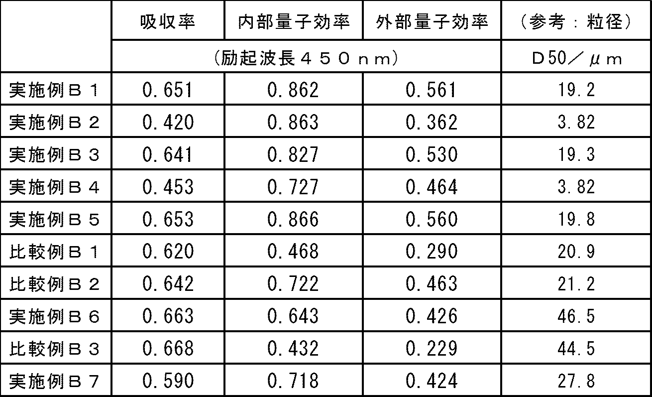
得られた粉末製品の粒度分布を、気流分散式レーザー回折法粒度分布測定器(HELOS&RODOS、Sympatec社製)によって測定した。その結果、粒径8.4μm以下の粒子が全体積の10%(D10=8.4μm)、粒径19.2μm以下の粒子が全体積の50%(D50=19.2μm)、粒径29.3μm以下の粒子が全体積の90%を占めた(D90=29.3μm)。
実施例B1と同じケイフッ化水素酸水溶液42.2cm3を50%HF532cm3にと混合した。これに、これに、実施例A1で作製したK2MnF6粉末を2.40g加えて撹拌し溶解させた(Si-F-Mn溶液)。
これとは別に、KF28.2gを純水286cm3に溶解させた(KF溶液)。
Si-F-Mn溶液を撹拌しながら、KF溶液を少しずつ加えていったところ、淡橙色の沈殿が生じた。この沈殿をブフナー漏斗でろ別し、できるだけ脱液した。更にアセトンで洗浄し、脱液、真空乾燥して、粉末製品K2SiF6:Mn36.3gを得た。
この粉末製品について実施例B1と同様にして測定した粒度分布の結果は、D10=0.99μm、D50=3.82μm、D90=7.26μmであった。
実施例A3で作製したK2MnF6粉末2.66gを用いたことのほかは実施例B1と同様にして、粉末製品K2SiF6:Mn36.4gを得た。
実施例B1と同様にして測定した粒度分布の結果は、D10=8.5μm、D50=19.3μm、D90=29.5μmであった。
実施例A3で作製したK2MnF6粉末2.40gを用いたことのほかは実施例B2と同様にして、粉末製品K2SiF6:Mn36.2gを得た。
実施例B1と同様にして測定した粒度分布の結果は、D10=0.98μm、D50=3.69μm、D90=7.24μmであった。
実施例A5で作製したK2MnF6粉末2.66gを用いたことのほかは実施例B1と同様にして、粉末製品K2SiF6:Mn36.5gを得た。
実施例B1と同様にして測定した粒度分布の結果は、D10=8.7μm、D50=19.8μm、D90=29.9μmであった。
40質量%のチタンフッ化水素酸(H2TiF6)水溶液(森田化学工業(株)製)15.6cm3を、まず50質量%HF100cm3と混合した。これに、実施例B1と同じK2MnF6粉末を0.74g加えて撹拌して溶解させ、Ti、FとMnを含む水溶液(Ti-F-Mn溶液)を調製した。
また、23.43gのKHF2を22cm3の50%HFと34cm3の純水に溶解させ、フッ化カリウムを含む水溶液(KF溶液)を調製した。
次に、撹拌したTi-F-Mn溶液に、KF溶液を約2分間かけて少しずつ加え、10分間程度撹拌し、淡橙色の固体が生成した。この固体生成物をろ別し、アセトンで洗浄し真空乾燥して、13.7gのK2TiF6:Mn粉末製品を得た。実施例B1同様にして測定した粒度分布の結果は、D10=13.6μm、D50=46.5μm、D90=103.2μmであった。
実施例B1と同じケイフッ化水素酸水溶液を同様に50%HFに混合した液に、実施例A9で得られた化合物2.31gを溶解させた(Si-F-Mn溶液)。
これとは別に、フッ化水素ナトリウム(ステラケミファ(株)製酸性フッ化ナトリウム、NaHF2)33.4gを50%HF195cm3、純水195cm3と混合し溶解させた(NaF溶液)。
Si-F-Mn溶液を撹拌しながら、NaF溶液を少しずつ加えていったところ、淡橙色の沈殿が生じた。この沈殿をブフナー漏斗でろ別し、できるだけ脱液した。更にアセトンで洗浄し、脱液、真空乾燥して、粉末製品Na2SiF6:Mn31.1gを得た。実施例B1同様にして測定した粒度分布の結果は、D10=11.6μm、D50=27.8μm、D90=46.6μmであった。
比較例A1で作製したマンガン中間体粉末2.66gを用いたことのほかは実施例B1と同様にして、粉末製品K2SiF6:Mn35.9gを得た。
実施例B1と同様にして測定した粒度分布の結果は、D10=8.9μm、D50=20.9μm、D90=31.0μmであった。
比較例A2で作製したマンガン中間体粉末2.66gを用いたことのほかは実施例B1と同様にして、粉末製品35.7gを得た。
実施例B1と同様にして測定した粒度分布の結果は、D10=9.0μm、D50=21.2μm、D90=31.0μmであった。
比較例A1で作製したマンガン中間体粉末0.74gを用いたことのほかは実施例B6と同様にして、粉末製品K2TiF6:Mn13.6gを得た。
実施例B1と同様にして測定した粒度分布の結果は、D10=13.3μm、D50=44.5μm、D90=99.4μmであった。

11 隔膜
12a、12b 室
13a、13b 電極
14 撹拌機
Claims (11)
- 原子価が4に満たない及び/又は4を超えるマンガンを含む化合物とフッ化水素とを含有する反応用液に陽極と陰極を挿入し、これら陽陰極間に電流密度100~1000A/m2の電流を流すことを特徴とするヘキサフルオロマンガン(IV)酸塩の製造方法。
- 上記反応用液を入れる反応槽を隔膜で仕切って、一方の室を陽極を挿入する陽極室とし、他方の室を陰極を挿入する陰極室とし、上記陽陰極間に電流を流すようにした請求項1記載の製造方法。
- 陽極室に原子価が4に満たないマンガンを含む化合物とフッ化水素とを含有する反応用液を入れ、陰極室にフッ化水素を含み、マンガンを含まない溶液を入れるようにした請求項2記載の製造方法。
- 陰極室に原子価が4を超えるマンガンを含む化合物とフッ化水素とを含有する反応用液を入れ、陽極室にフッ化水素を含み、マンガンを含まない溶液を入れるようにした請求項2記載の製造方法。
- 陽極室に原子価が4に満たないマンガンを含む化合物とフッ化水素とを含有する反応用液を入れ、陰極室に原子価が4を超えるマンガンを含む化合物とフッ化水素とを含有する反応用液を入れるようにした請求項2記載の製造方法。
- 隔膜がイオン交換膜である請求項2~5のいずれか1項記載の製造方法。
- 電流が直流である請求項1~6のいずれか1項記載の製造方法。
- 反応の初めから終わりまでのいずれかの段階で、反応用液に下記式(1)
AF又はAHF2 (1)
(式中、AはLi、Na、K、Rb、Csの中から選ばれる1種又は2種以上のアルカリ金属元素であって、少なくともNa又はKを含む。)
で表されるアルカリ金属フッ化物又はフッ化水素塩を添加して、下記式(2)
A2MnF6 (2)
(式中、Aは上記の通りである。)
で表されるヘキサフルオロマンガン(IV)アルカリ金属塩を反応液中に沈殿、回収するようにした請求項1~7のいずれか1項記載の製造方法。 - 表面付近の酸素含有量が1原子%以下であるヘキサフルオロマンガン(IV)酸塩。
- 請求項1~8のいずれか1項記載の製造方法で得られたヘキサフルオロマンガン(IV)酸塩を、元素Aを含む化合物及び元素Mを含む化合物(AはLi、Na、K、Rb、Csの中から選ばれる1種又は2種以上のアルカリ金属元素であって、少なくともNa又はKを含む。MはSi、Ti、Zr、Hf、Ge及びSnから選ばれる1種又は2種以上の元素)と共に、フッ化水素の存在下に混合することを特徴とする下記式(3)
A2MF6:Mn (3)
(式中、A及びMは上記の通りである。)
で表される複フッ化物蛍光体の製造方法。 - 表面付近の酸素含有量が1原子%以下である下記式(3)
A2MF6:Mn (3)
(式中、AはLi、Na、K、Rb、Csの中から選ばれる1種又は2種以上のアルカリ金属元素であって、少なくともNa又はKを含む。MはSi、Ti、Zr、Hf、Ge及びSnから選ばれる1種又は2種以上の元素である。)
で表される複フッ化物蛍光体。
Priority Applications (2)
| Application Number | Priority Date | Filing Date | Title |
|---|---|---|---|
| US15/115,580 US10316248B2 (en) | 2014-01-30 | 2015-01-15 | Hexafluoromanganate (IV), complex fluoride phosphor, and methods respectively for producing said products |
| KR1020167022442A KR102226178B1 (ko) | 2014-01-30 | 2015-01-15 | 헥사플루오로망가니즈(iv)산염, 복불화물 형광체 및 그것들의 제조 방법 |
Applications Claiming Priority (4)
| Application Number | Priority Date | Filing Date | Title |
|---|---|---|---|
| JP2014015619 | 2014-01-30 | ||
| JP2014-015619 | 2014-01-30 | ||
| JP2014231457A JP6327125B2 (ja) | 2014-01-30 | 2014-11-14 | ヘキサフルオロマンガン(iv)酸塩及び複フッ化物蛍光体並びにそれらの製造方法 |
| JP2014-231457 | 2014-11-14 |
Publications (1)
| Publication Number | Publication Date |
|---|---|
| WO2015115188A1 true WO2015115188A1 (ja) | 2015-08-06 |
Family
ID=53756765
Family Applications (1)
| Application Number | Title | Priority Date | Filing Date |
|---|---|---|---|
| PCT/JP2015/050906 Ceased WO2015115188A1 (ja) | 2014-01-30 | 2015-01-15 | ヘキサフルオロマンガン(iv)酸塩及び複フッ化物蛍光体並びにそれらの製造方法 |
Country Status (5)
| Country | Link |
|---|---|
| US (1) | US10316248B2 (ja) |
| JP (1) | JP6327125B2 (ja) |
| KR (1) | KR102226178B1 (ja) |
| TW (1) | TWI645016B (ja) |
| WO (1) | WO2015115188A1 (ja) |
Cited By (1)
| Publication number | Priority date | Publication date | Assignee | Title |
|---|---|---|---|---|
| JPWO2022044860A1 (ja) * | 2020-08-25 | 2022-03-03 |
Families Citing this family (7)
| Publication number | Priority date | Publication date | Assignee | Title |
|---|---|---|---|---|
| JP6603458B2 (ja) * | 2015-02-12 | 2019-11-06 | 株式会社東芝 | 蛍光体、およびその製造方法、ならびにその蛍光体を用いた発光装置 |
| JP2017210580A (ja) * | 2016-05-27 | 2017-11-30 | 株式会社東芝 | 蛍光体、およびその製造方法、ならびにその蛍光体を用いた発光装置 |
| JP6359066B2 (ja) | 2016-10-04 | 2018-07-18 | デンカ株式会社 | マンガン付活複フッ化物蛍光体原料用のフッ化マンガン酸カリウム及びそれを用いたマンガン付活複フッ化物蛍光体の製造方法 |
| JP6826445B2 (ja) * | 2017-01-31 | 2021-02-03 | デンカ株式会社 | 六フッ化マンガン酸カリウム及びそれを用いたマンガン付活複フッ化物蛍光体 |
| CN110615474A (zh) * | 2019-09-16 | 2019-12-27 | 九江学院 | 一种热阴极用铪酸盐电子发射活性物质的制备方法 |
| JP7335520B2 (ja) | 2021-06-21 | 2023-08-30 | 日亜化学工業株式会社 | 波長変換部材、発光装置及び画像表示装置 |
| US12545836B2 (en) | 2021-06-21 | 2026-02-10 | Nichia Corporation | Fluoride phosphor and method of producing the same, wavelength conversion member, and light emitting device |
Citations (3)
| Publication number | Priority date | Publication date | Assignee | Title |
|---|---|---|---|---|
| WO2009119486A1 (ja) * | 2008-03-25 | 2009-10-01 | 国立大学法人群馬大学 | 蛍光体及びその製造方法並びに該蛍光体を用いた白色発光ダイオード |
| JP2012224536A (ja) * | 2011-04-08 | 2012-11-15 | Shin-Etsu Chemical Co Ltd | 複フッ化物及び複フッ化物蛍光体の製造方法 |
| WO2014103932A1 (ja) * | 2012-12-28 | 2014-07-03 | 信越化学工業株式会社 | 蛍光体の表面処理方法 |
Family Cites Families (5)
| Publication number | Priority date | Publication date | Assignee | Title |
|---|---|---|---|---|
| US3576756A (en) | 1968-06-12 | 1971-04-27 | Mallinckrodt Chemical Works | Fluocomplexes of titanium, silicon, tin and germanium, activated by tetravalent manganese |
| US7648649B2 (en) | 2005-02-02 | 2010-01-19 | Lumination Llc | Red line emitting phosphors for use in led applications |
| US7497973B2 (en) | 2005-02-02 | 2009-03-03 | Lumination Llc | Red line emitting phosphor materials for use in LED applications |
| US8491816B2 (en) | 2008-02-07 | 2013-07-23 | Mitsubishi Chemical Corporation | Semiconductor light emitting device, backlight, color image display device and phosphor to be used for them |
| JP5682104B2 (ja) | 2008-09-05 | 2015-03-11 | 三菱化学株式会社 | 蛍光体及びその製造方法と、その蛍光体を用いた蛍光体含有組成物及び発光装置、並びに、その発光装置を用いた画像表示装置及び照明装置 |
-
2014
- 2014-11-14 JP JP2014231457A patent/JP6327125B2/ja active Active
-
2015
- 2015-01-15 WO PCT/JP2015/050906 patent/WO2015115188A1/ja not_active Ceased
- 2015-01-15 KR KR1020167022442A patent/KR102226178B1/ko active Active
- 2015-01-15 US US15/115,580 patent/US10316248B2/en active Active
- 2015-01-29 TW TW104103049A patent/TWI645016B/zh active
Patent Citations (3)
| Publication number | Priority date | Publication date | Assignee | Title |
|---|---|---|---|---|
| WO2009119486A1 (ja) * | 2008-03-25 | 2009-10-01 | 国立大学法人群馬大学 | 蛍光体及びその製造方法並びに該蛍光体を用いた白色発光ダイオード |
| JP2012224536A (ja) * | 2011-04-08 | 2012-11-15 | Shin-Etsu Chemical Co Ltd | 複フッ化物及び複フッ化物蛍光体の製造方法 |
| WO2014103932A1 (ja) * | 2012-12-28 | 2014-07-03 | 信越化学工業株式会社 | 蛍光体の表面処理方法 |
Cited By (3)
| Publication number | Priority date | Publication date | Assignee | Title |
|---|---|---|---|---|
| JPWO2022044860A1 (ja) * | 2020-08-25 | 2022-03-03 | ||
| WO2022044860A1 (ja) * | 2020-08-25 | 2022-03-03 | デンカ株式会社 | フッ化物蛍光体、複合体および発光装置 |
| JP7554833B2 (ja) | 2020-08-25 | 2024-09-20 | デンカ株式会社 | フッ化物蛍光体、複合体および発光装置 |
Also Published As
| Publication number | Publication date |
|---|---|
| US20170066964A1 (en) | 2017-03-09 |
| TW201540813A (zh) | 2015-11-01 |
| US10316248B2 (en) | 2019-06-11 |
| JP2015163733A (ja) | 2015-09-10 |
| JP6327125B2 (ja) | 2018-05-23 |
| KR102226178B1 (ko) | 2021-03-10 |
| KR20160114622A (ko) | 2016-10-05 |
| TWI645016B (zh) | 2018-12-21 |
Similar Documents
| Publication | Publication Date | Title |
|---|---|---|
| JP6327125B2 (ja) | ヘキサフルオロマンガン(iv)酸塩及び複フッ化物蛍光体並びにそれらの製造方法 | |
| JP5845999B2 (ja) | 複フッ化物蛍光体の製造方法 | |
| JP6394307B2 (ja) | 複フッ化物蛍光体及びその製造方法 | |
| WO2015115189A1 (ja) | 複フッ化物蛍光体の製造方法及び処理方法 | |
| TWI641727B (zh) | Method for producing complex fluoride phosphor | |
| JP6614072B2 (ja) | Mn賦活複フッ化物蛍光体及びその製造方法 | |
| WO2015115193A1 (ja) | 複フッ化物蛍光体及びその製造方法 | |
| JP2018062596A (ja) | 赤色蛍光体及びその製造方法 | |
| JP2015163709A (ja) | 複フッ化物蛍光体の製造方法 | |
| US20150266745A1 (en) | Metal Cyanometallate Synthesis Method | |
| CN104372380A (zh) | 一种低温熔盐法制备高纯铬 | |
| JP6112029B2 (ja) | 複フッ化物蛍光体の製造方法 | |
| TWI754595B (zh) | 釩電解液的製造方法 | |
| CN109208034A (zh) | 一种低温电解氯化钕制备稀土金属钕的方法 | |
| JP2014111828A (ja) | 水酸化ニッケルとその製造方法および得られる酸化ニッケル | |
| JP2015004096A (ja) | ニッケル水酸化物の製造方法 | |
| TW201801385A (zh) | 含混合鹵素與硫酸釩電解液製備方法 |
Legal Events
| Date | Code | Title | Description |
|---|---|---|---|
| 121 | Ep: the epo has been informed by wipo that ep was designated in this application |
Ref document number: 15742588 Country of ref document: EP Kind code of ref document: A1 |
|
| WWE | Wipo information: entry into national phase |
Ref document number: 15115580 Country of ref document: US |
|
| NENP | Non-entry into the national phase |
Ref country code: DE |
|
| ENP | Entry into the national phase |
Ref document number: 20167022442 Country of ref document: KR Kind code of ref document: A |
|
| 122 | Ep: pct application non-entry in european phase |
Ref document number: 15742588 Country of ref document: EP Kind code of ref document: A1 |