WO2015114853A1 - レーザー加工機のシールドガス供給装置及びレーザー加工機 - Google Patents
レーザー加工機のシールドガス供給装置及びレーザー加工機 Download PDFInfo
- Publication number
- WO2015114853A1 WO2015114853A1 PCT/JP2014/068413 JP2014068413W WO2015114853A1 WO 2015114853 A1 WO2015114853 A1 WO 2015114853A1 JP 2014068413 W JP2014068413 W JP 2014068413W WO 2015114853 A1 WO2015114853 A1 WO 2015114853A1
- Authority
- WO
- WIPO (PCT)
- Prior art keywords
- shield gas
- supply device
- gas supply
- laser beam
- laser
- Prior art date
- Legal status (The legal status is an assumption and is not a legal conclusion. Google has not performed a legal analysis and makes no representation as to the accuracy of the status listed.)
- Ceased
Links
Images




Classifications
-
- B—PERFORMING OPERATIONS; TRANSPORTING
- B23—MACHINE TOOLS; METAL-WORKING NOT OTHERWISE PROVIDED FOR
- B23K—SOLDERING OR UNSOLDERING; WELDING; CLADDING OR PLATING BY SOLDERING OR WELDING; CUTTING BY APPLYING HEAT LOCALLY, e.g. FLAME CUTTING; WORKING BY LASER BEAM
- B23K26/00—Working by laser beam, e.g. welding, cutting or boring
- B23K26/14—Working by laser beam, e.g. welding, cutting or boring using a fluid stream, e.g. a jet of gas, in conjunction with the laser beam; Nozzles therefor
-
- B—PERFORMING OPERATIONS; TRANSPORTING
- B23—MACHINE TOOLS; METAL-WORKING NOT OTHERWISE PROVIDED FOR
- B23K—SOLDERING OR UNSOLDERING; WELDING; CLADDING OR PLATING BY SOLDERING OR WELDING; CUTTING BY APPLYING HEAT LOCALLY, e.g. FLAME CUTTING; WORKING BY LASER BEAM
- B23K26/00—Working by laser beam, e.g. welding, cutting or boring
- B23K26/08—Devices involving relative movement between laser beam and workpiece
- B23K26/082—Scanning systems, i.e. devices involving movement of the laser beam relative to the laser head
-
- B—PERFORMING OPERATIONS; TRANSPORTING
- B23—MACHINE TOOLS; METAL-WORKING NOT OTHERWISE PROVIDED FOR
- B23K—SOLDERING OR UNSOLDERING; WELDING; CLADDING OR PLATING BY SOLDERING OR WELDING; CUTTING BY APPLYING HEAT LOCALLY, e.g. FLAME CUTTING; WORKING BY LASER BEAM
- B23K26/00—Working by laser beam, e.g. welding, cutting or boring
- B23K26/14—Working by laser beam, e.g. welding, cutting or boring using a fluid stream, e.g. a jet of gas, in conjunction with the laser beam; Nozzles therefor
- B23K26/1462—Nozzles; Features related to nozzles
- B23K26/1464—Supply to, or discharge from, nozzles of media, e.g. gas, powder, wire
- B23K26/147—Features outside the nozzle for feeding the fluid stream towards the workpiece
-
- B—PERFORMING OPERATIONS; TRANSPORTING
- B23—MACHINE TOOLS; METAL-WORKING NOT OTHERWISE PROVIDED FOR
- B23K—SOLDERING OR UNSOLDERING; WELDING; CLADDING OR PLATING BY SOLDERING OR WELDING; CUTTING BY APPLYING HEAT LOCALLY, e.g. FLAME CUTTING; WORKING BY LASER BEAM
- B23K26/00—Working by laser beam, e.g. welding, cutting or boring
- B23K26/20—Bonding
- B23K26/21—Bonding by welding
-
- B—PERFORMING OPERATIONS; TRANSPORTING
- B23—MACHINE TOOLS; METAL-WORKING NOT OTHERWISE PROVIDED FOR
- B23K—SOLDERING OR UNSOLDERING; WELDING; CLADDING OR PLATING BY SOLDERING OR WELDING; CUTTING BY APPLYING HEAT LOCALLY, e.g. FLAME CUTTING; WORKING BY LASER BEAM
- B23K26/00—Working by laser beam, e.g. welding, cutting or boring
- B23K26/20—Bonding
- B23K26/32—Bonding taking account of the properties of the material involved
-
- B—PERFORMING OPERATIONS; TRANSPORTING
- B23—MACHINE TOOLS; METAL-WORKING NOT OTHERWISE PROVIDED FOR
- B23K—SOLDERING OR UNSOLDERING; WELDING; CLADDING OR PLATING BY SOLDERING OR WELDING; CUTTING BY APPLYING HEAT LOCALLY, e.g. FLAME CUTTING; WORKING BY LASER BEAM
- B23K2103/00—Materials to be soldered, welded or cut
- B23K2103/08—Non-ferrous metals or alloys
- B23K2103/14—Titanium or alloys thereof
Definitions
- the present invention relates to a shield gas supply device for a laser processing machine and a laser processing machine.
- Patent Literature 1 and Patent Literature 2 disclose an apparatus capable of performing laser processing while supplying a shielding gas.
- various materials have been used as work materials, and various methods have been used as laser processing methods.
- titanium or a titanium alloy may be used as a workpiece. Since titanium and titanium alloys are extremely active at high temperatures, if oxygen or nitrogen is present at the processing temperature (welding temperature), they are easily absorbed as impurities. When oxygen or nitrogen is absorbed as an impurity in titanium or a titanium alloy, it may cause toughness reduction or blowhole generation.
- a galvano scanner system that moves a laser irradiation position in a wide range at high speed by driving a laser reflecting mirror at high speed is used.
- a high concentration of shielding gas must be filled around the processing portion over a wide range.
- an object of the present invention is to efficiently eject a shielding gas to a workpiece when performing laser processing with a laser processing machine.
- the shield gas supply device for a laser beam machine for solving the above-described problem includes a ring-shaped portion disposed at a position surrounding a laser irradiated to a workpiece from the laser beam machine, A supply pipe for supplying a shield gas to the ring-shaped part, and the ring-shaped part has a moving path of the shield gas supplied from the supply pipe in a circumferential direction of the ring-shaped part, The movement path is arranged in multiple stages with respect to the workpiece, and a hole is provided in the inner peripheral portion of the ring-shaped portion to inject the shield gas so as to form a swirling flow in the circumferential direction. It is characterized by being.
- the “ring-shaped part” is not limited to a perfect circular ring-shaped member, and includes an elliptical shape or a polygonal shape.
- the moving path is provided with a hole for ejecting the shield gas so as to form a swirling flow in the circumferential direction in the inner peripheral portion of the ring-shaped portion. For this reason, the swirling flow of the shield gas is generated in the processing portion surrounded by the ring-shaped portion irradiated with the laser, and the processing portion is easily filled with the high-concentration shielding gas.
- route is arrange
- the swirl flow of the shield gas can be generated in multiple stages by the moving paths arranged in multiple stages. For this reason, even if the swirl flow of the shield gas generated by the hole of the moving path disposed near the workpiece entrains surrounding gas, the shield gas is disposed far from the workpiece. A swirl flow of the shield gas generated by the hole portion of the movement path is involved. That is, since the shielding gas is involved rather than air, a decrease in the concentration of shielding gas around the processed portion can be suppressed. From these things, according to this aspect, when performing laser processing with a laser processing machine, a shielding gas can be efficiently ejected to a workpiece.
- the shield gas supply apparatus for a laser beam machine according to a second aspect of the present invention is the laser gas machine according to the first aspect, wherein the hole moves along the movement path of the shield gas from a direction toward the center of the ring-shaped portion.
- the shield gas is ejected in a direction inclined to the downstream side of the direction.
- the hole ejects the shield gas in a direction inclined from the direction toward the center of the ring-shaped portion to the downstream side in the movement direction of the shield gas in the movement path. For this reason, since the shield gas can be ejected using the flow of the shield gas in the moving direction, the shield gas can be ejected vigorously. That is, the swirl flow of the shield gas can be efficiently generated, and the shield gas can be efficiently ejected onto the workpiece when performing laser processing with a laser processing machine.
- the hole portion provided in each of the movement paths arranged in multiple stages is provided in the circumferential direction. It is provided in the same position.
- the same position in the circumferential direction is meant to include not only the same position in the circumferential direction in a strict sense but also a position slightly shifted in the circumferential direction.
- the hole provided in each of the movement paths arranged in multiple stages is provided at the same position in the circumferential direction. For this reason, even if the swirl flow of the shield gas generated by the hole portion of the moving path arranged near the workpiece entrains surrounding gas, entraining a gas having a high concentration of the shield gas; Become. That is, it is possible to more effectively suppress the decrease in the concentration of the shielding gas around the processed portion.
- the shield gas supply device for a laser beam machine is characterized in that, in any one of the first to third aspects, a wall portion surrounding the ring-shaped portion in the circumferential direction is provided.
- the wall portion surrounding the ring-shaped portion in the circumferential direction is provided. For this reason, it can suppress that the said shield gas escapes from the said process part periphery by the said wall part, and can suppress more effectively the density
- the shield gas supply apparatus for a laser beam machine is the laser gas machine according to any one of the first to fourth aspects, in the vicinity of the workpiece in the movement path arranged in multiple stages.
- the first ejection amount of the shield gas ejected from the hole provided in the first movement path disposed in the second is disposed far from the workpiece in the movement path disposed in multiple stages. It is characterized by being smaller than the second ejection amount of the shield gas ejected from the hole provided in the movement path.
- the first ejection amount is larger than the second ejection amount, entrainment of gas around the swirling flow of the shield gas generated by the hole portion of the first movement path. It has been found that the amount increases and the concentration of the shielding gas around the processed portion may be lowered. According to this aspect, the first ejection amount is smaller than the second ejection amount. For this reason, the density
- the shield gas supply apparatus for a laser beam machine is the fifth aspect, wherein the second ejection amount relative to the sum of the first ejection amount and the second ejection amount is 0.55. It is characterized by being 0.65 or less.
- the concentration reduction of the shielding gas can be more effectively suppressed.
- the concentration of the shielding gas around the processing portion Reduction can be suppressed more effectively.
- a shield gas supply device for a laser beam machine in any one of the first to sixth aspects, is near the workpiece in the movement path arranged in multiple stages.
- the first inclination angle of the inclined direction with respect to the direction toward the center of the ring-shaped part of the shield gas ejected from the hole provided in the first movement path arranged in the first movement path is the movement path arranged in multiple stages.
- the first tilt angle exceeds the second tilt angle, the generation of the swirling flow of the shield gas by the first movement path is promoted, but the swirling of the shield gas. It has been found that the amount of the shielding gas that reaches the center of the ring-shaped portion may be reduced due to a strong flow.
- the first inclination angle is not more than the second inclination angle. For this reason, when the shield gas reaches the center of the ring-shaped portion and laser processing is performed by a laser processing machine, the shield gas can be efficiently ejected to the workpiece.
- the shield gas supply apparatus for a laser beam machine is the seventh aspect, wherein the first inclination angle is 5.625 ° or more and 7.5 ° or less, and the second inclination angle. Is 7.5 ° or more and 15 ° or less.
- the first tilt angle is 5.625 ° to 7.5 °
- the second tilt angle is 7.5 ° to 15 °. It has been found that the shield gas concentration around the processed portion can be increased while the shield gas reaches the center of the ring-shaped portion.
- the first inclination angle is 5.625 ° to 7.5 °
- the second inclination angle is 7.5 ° to 15 °. For this reason, when performing laser processing with a laser processing machine, it is possible to inject the shielding gas efficiently to the workpiece.
- a laser beam machine includes the shield gas supply device of the laser beam machine according to any one of the first to eighth aspects, and a laser irradiation unit that irradiates the laser. Characterized by
- laser processing can be performed by efficiently ejecting the shielding gas to the workpiece.
- FIG. 1 is a schematic view of a laser beam machine 1 according to this embodiment.
- the laser processing machine 1 of this embodiment includes a laser irradiation unit 2 having a laser oscillator 4, a transmission fiber 5, and a galvano scanner head 6.
- the laser irradiation unit 2 irradiates the workpiece M with the laser L from the galvano scanner head 6.
- the laser processing machine 1 of the present embodiment includes a ring-shaped portion 8 disposed at a position surrounding the laser L irradiated to the workpiece M from the laser irradiation portion 2, and a ring by flowing a shield gas in the direction A.
- a shield gas supply device 3 having a supply pipe 7 for supplying a shield gas to the shape portion 8 is provided. Detailed description of the shield gas supply device 3 will be described later.
- argon (Ar) is used as the shielding gas, but the present invention is not limited to this.
- the workpiece containing titanium is used as the workpiece M, it is not limited to this.
- the laser processing machine 1 of the present embodiment includes an air discharge unit 10 that discharges air in the direction C by flowing air in the direction B through the supply pipe 9.
- the air discharge part 10 serves as an air curtain, and when the workpiece M is processed (welded), the melted workpiece scattered from the processed portion (the laser irradiation portion of the workpiece M). M prevents the galvano scanner head 6 from getting dirty.
- the laser beam machine 1 according to the present embodiment represents a state in which the workpiece surface is being machined on the workpiece M in the vertical direction, but the workpiece surface is inclined from the vertical direction. In this configuration, the workpiece M can be machined in the horizontal direction or the horizontal direction.
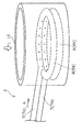
- FIG. 2 is a schematic perspective view showing the shield gas supply device 3 of the laser beam machine 1 of the present embodiment.
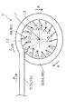
- FIG. 3 is a schematic plan view showing the shield gas supply device 3 of the laser beam machine 1 of the present embodiment.
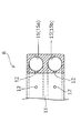
- FIG. 4 is a schematic cross-sectional view of the ring-shaped part 8 which is a main part of the shield gas supply device 3 of the laser beam machine 1 of the present embodiment.
- FIGS. 2 to 4 show the shield gas supply device 3 when processing is performed by irradiating a workpiece L having a horizontal processing surface with a laser L from a vertically upward direction.
- the shield gas supply device 3 of the present embodiment is configured such that a member formed by bending a member on a tube with a sealed tip into a ring shape is against a workpiece.
- a member formed by bending a member on a tube with a sealed tip into a ring shape is against a workpiece.
- the galvano scanner head side is the ring-shaped portion 8a
- the side in contact with the workpiece is the ring-shaped portion 8b.
- the supply pipe 7a supplies the shield gas to the ring-shaped portion 8a
- the supply pipe 7b supplies the shield gas to the ring-shaped portion 8a.
- a plurality of holes 12 for injecting shield gas to the inner side 13 of the ring-shaped portion 8 are provided in the inner peripheral portion 11a of the ring-shaped portion 8a and the inner peripheral portion 11b of the ring-shaped portion 8b.
- the hole 12 is positioned at every 22.5 ° as viewed from the center 14 of the ring-shaped portion 8 in each of the inner peripheral portion 11 a and the inner peripheral portion 11 b. Sixteen are provided at equal intervals.
- the laser L emitted from the galvano scanner head 6 is emitted toward the inner side 13 of the ring-shaped portion 8. That is, the inner side 13 of the ring-shaped part 8 is a processed part.
- the shield gas is ejected from each hole 12 in a direction D inclined from the direction toward the center 14 of the ring-shaped portion 8 to the downstream side of the moving direction A in the moving path of the shield gas.
- the ring-shaped part 8 of the present embodiment is formed by bending a member on a pipe whose tip is sealed into a ring shape, the tubular part 15 serving as the shield gas moving path is bent. It was constructed at the same time. With this configuration, the shield gas supply device 3 can be easily manufactured.
- the tubular portion 15 of the present embodiment configures the moving path of the shield gas supplied from the supply pipe 7 in the circumferential direction of the ring-shaped portion 8, and the workpiece M In contrast, it is arranged in multiple stages.
- the inner circumferential portions 11 a and 11 b of the ring-shaped portion 8 are provided with holes 12 through which the shield gas is ejected in a direction D inclined from the direction toward the center 14 of the ring-shaped portion 8.
- the tubular portion 15 has the hole portion 12 that ejects the shielding gas to the inner peripheral portions 11 a and 11 of the ring-shaped portion 8 in the direction D inclined from the direction toward the center 14 of the ring-shaped portion 8. Is provided.
- the shield gas supply device 3 of the present embodiment is configured such that the shield gas can be efficiently ejected to the workpiece M when the laser processing machine 1 performs laser processing.
- the hole 12 is inclined from the direction D toward the center 14 of the ring-shaped portion 8 to the downstream side in the moving direction A in the moving path of the shield gas.
- the shield gas is ejected in the direction D.
- the shield gas can be ejected vigorously. That is, the swirl flow of the shielding gas can be efficiently generated, and the shielding gas can be efficiently ejected onto the workpiece when the laser processing machine 1 performs laser processing.
- the first inclination angle ⁇ b with respect to the direction toward the center 14 ejected from the hole 12 provided in the first tubular portion 15b is a hole provided in the second tubular portion 15a.
- the first inclination angle ⁇ b is equal to or smaller than the second inclination angle ⁇ a. For this reason, the shield gas can reach the center 14, and the shield gas can be efficiently ejected to the workpiece M when the laser processing is performed by the laser processing machine 1.
- the first inclination angle ⁇ b is 5.625 ° to 7.5 °
- the second inclination angle ⁇ a is 7.5 ° to 15 °.
- the first inclination angle ⁇ b is 5.625 ° or more and 7.5 ° or less
- the second inclination angle ⁇ a is 7.5 ° or more and 15 ° or less. It has been found that the concentration of the shielding gas around the processed portion can be increased while the shielding gas reaches the center 14. For this reason, the shield gas supply device 3 of the present embodiment is configured so that the shield gas can be efficiently ejected onto the workpiece M, particularly when laser processing is performed by the laser processing machine 1.
- the hole portions 12 provided in each of the tubular portions 15 arranged in multiple stages are arranged in the circumferential direction of the ring-shaped portion 8. It is provided at the same position.
- the hole 12 provided in the first tubular portion 15b is provided directly below the hole 12 provided in the second tubular portion 15a. For this reason, even if the swirling flow of the shield gas generated by the hole 12 of the first tubular portion 15b entrains the surrounding gas, the gas having a high concentration of the shield gas is entrained. That is, the configuration is such that a decrease in the concentration of the shielding gas around the processed portion can be more effectively suppressed.
- the shield gas supply device 3 of the present embodiment although it is the same position in the circumferential direction in a strict sense, it has the above effect even in a position slightly shifted in the circumferential direction. The position may be slightly shifted.
- the first ejection amount of the shield gas ejected from the hole portion 12 provided in the first tubular portion 15b is ejected from the hole portion 12 provided in the second tubular portion 15a.
- the shield gas is configured to be smaller than the second ejection amount of the shield gas.
- the second ejection amount with respect to the sum of the first ejection amount and the second ejection amount is configured to be 0.55 or more and 0.65 or less.
- total ejection amount is configured to be 0.55 or more and 0.65 or less.
- the result of calculating the shield gas distribution inside the ring-shaped portion 8 by CFD (Computational Fluid Dynamics) analysis is shown.
- CFD Computer Fluid Dynamics
- the ratio of the second ejection amount to the total ejection amount is 0.55 or more and 0.65 or less, it becomes 0.4 or more, which is a preferable mass distribution of the shielding gas (Ar). ing.
- the shield gas supply apparatus 3 of a present Example has the structure which can suppress more effectively the fall of the density
- FIG. 6 is a schematic perspective view showing the shield gas supply device 3 of the laser beam machine 1 of the present embodiment.
- FIG. 7 is a schematic cross-sectional view of the ring-shaped portion 8 that is a main portion of the shield gas supply device 3 of the laser beam machine 1 of the present embodiment.
- FIGS. 6 to 7 show the shield gas supply device 3 when processing is performed by irradiating a workpiece L having a horizontal processing surface with a laser L from a vertically upward direction.
- the same components as those in the above embodiment are denoted by the same reference numerals, and detailed description thereof is omitted.
- the shield gas supply device 3 of the present embodiment is not configured by bending a member on a pipe whose tip is sealed into a ring shape, but is provided with a tubular portion 15 on a member configured in a ring shape. It is configured by performing processing separately. However, the position of the hole 12, the jet direction of the shield gas, and the jet amount are the same as those of the shield gas supply device 3 of the first embodiment.
- the shield gas supply device 3 of the present embodiment has the same characteristics as the shield gas supply device 3 of the first embodiment, although there are the above-described structural differences from the shield gas supply device 3 of the first embodiment. is doing. For this reason, when performing laser processing with the laser processing machine 1, the shield gas can be efficiently ejected to the workpiece M.
- FIG. 8 is a schematic perspective view showing the shield gas supply device 3 of the laser beam machine 1 of the present embodiment.
- FIG. 8 shows the shield gas supply device 3 when processing is performed by irradiating the workpiece M having a horizontal processing surface with a laser L from the vertical direction.
- the shield gas supply device 3 according to the present embodiment has the same configuration as that of the recording device 1 according to the first embodiment except that the wall portion 16 surrounding the ring-shaped portion 8 in the circumferential direction is provided.
- the shield gas supply device 3 of this embodiment includes the wall portion 16 that surrounds the ring-shaped portion 8 in the circumferential direction of the ring-shaped portion 8. For this reason, it can suppress that the said shielding gas escapes from the said process part periphery by the wall part 16, and it has the structure which can suppress the density
- the height of the wall portion 16 is preferably as high as possible as long as it does not hinder laser processing. This is because the shield gas can be effectively prevented from escaping.
- the tubular portion 15 has a two-stage configuration, but may have a three-stage or more configuration.
- the ring-shaped portion 8 has a true circular configuration, but may have an elliptical or polygonal configuration.
Landscapes
- Physics & Mathematics (AREA)
- Optics & Photonics (AREA)
- Engineering & Computer Science (AREA)
- Plasma & Fusion (AREA)
- Mechanical Engineering (AREA)
- Laser Beam Processing (AREA)
Abstract
レーザー加工機でレーザー加工を行う際に、被加工材に効率よくシールドガスを噴出することを課題とし、その解決手段として、レーザー加工機1から被加工材Mに照射されるレーザーLを囲む位置に配置されるリング状部8と、リング状部8にシールドガスを供給する供給管7と、を備え、リング状部8は、該リング状部8の周方向に、供給管7から供給される前記シールドガスの移動経路15を有し、移動経路15は、被加工材Mに対して多段に配置され、リング状部8の内周部分11に、前記周方向に旋回流を形成するように前記シールドガスを噴出する、孔部12が設けられている。
Description
本発明は、レーザー加工機のシールドガス供給装置及びレーザー加工機に関する。
従来からレーザー加工機のシールドガス供給装置が使用されている。例えば、特許文献1及び特許文献2には、シールドガスを供給しつつレーザー加工することが可能な装置が開示されている。
また、近年、被加工材として様々なものが使用されているとともに、レーザー加工方法として様々な方法が使用されている。
また、近年、被加工材として様々なものが使用されているとともに、レーザー加工方法として様々な方法が使用されている。
上記のように、近年、被加工材として様々なものが使用されている。例えば、被加工材としてチタンやチタン合金等が使用される場合がある。チタンやチタン合金は高温で極めて活性であるため、加工温度(溶接温度)において酸素や窒素が存在すると、不純物としてこれらを吸収しやすい。チタンやチタン合金において酸素や窒素を不純物として吸収すると、靱性低下やブローホールの発生などを引き起こす場合がある。
また、上記のように、近年、レーザー加工方法として様々な方法が使用されている。例えば、レーザー反射ミラーを高速に駆動することにより、高速かつ広範囲にレーザー照射位置を移動するガルバノスキャナシステムなどが使用されている。
例えば、ガルバノスキャナシステムを使用してチタンやチタン合金を溶接する場合、広範囲にわたり高濃度のシールドガスを加工部分周辺に満たしておかなければならない。
例えば、ガルバノスキャナシステムを使用してチタンやチタン合金を溶接する場合、広範囲にわたり高濃度のシールドガスを加工部分周辺に満たしておかなければならない。
しかしながら、特許文献1及び特許文献2に開示されるような、従来のレーザー加工機のシールドガス供給装置においては、近年の被加工材として様々なものが使用されていること及びレーザー加工方法として様々な方法が使用されていることに対応しきれていない場合があった。
すなわち、従来のレーザー加工機のシールドガス供給装置においては、レーザー加工機でレーザー加工を行う際に、被加工材に効率よくシールドガスを噴出することが、十分にできていない場合があった。
すなわち、従来のレーザー加工機のシールドガス供給装置においては、レーザー加工機でレーザー加工を行う際に、被加工材に効率よくシールドガスを噴出することが、十分にできていない場合があった。
そこで、本発明の目的は、レーザー加工機でレーザー加工を行う際に、被加工材に効率よくシールドガスを噴出することである。
上記課題を解決するための本発明の第1の態様に係るレーザー加工機のシールドガス供給装置は、レーザー加工機から被加工材に照射されるレーザーを囲む位置に配置されるリング状部と、前記リング状部にシールドガスを供給する供給管と、を備え、前記リング状部は、該リング状部の周方向に、前記供給管から供給される前記シールドガスの移動経路を有し、前記移動経路は、前記被加工材に対して多段に配置され、前記リング状部の内周部分に、前記周方向に旋回流を形成するように前記シールドガスを噴出する、孔部が設けられていることを特徴とする。
ここで、「リング状部」とは、真円形のリング状の部材に限定されず、楕円形や多角形のものも含む意味である。
本態様によれば、前記移動経路は、前記リング状部の内周部分に、前記周方向に旋回流を形成するように前記シールドガスを噴出する、孔部が設けられている。このため、前記レーザーが照射される前記リング状部で囲われた加工部分に、前記シールドガスの旋回流を発生させ、該加工部分を高濃度のシールドガスで満たしやすくなる。
また、本態様によれば、前記移動経路は、前記被加工材に対して多段に配置される。したがって、多段に配置される前記移動経路により前記シールドガスの旋回流を多段に発生させることができる。このため、前記被加工材の近くに配置される前記移動経路の前記孔部により発生した前記シールドガスの旋回流が周囲の気体を巻き込んだとしても、前記被加工材から遠くに配置される前記移動経路の前記孔部により発生した前記シールドガスの旋回流を巻き込むこととなる。すなわち、空気ではなく前記シールドガスを巻き込むこととなるため、前記加工部分周辺のシールドガスの濃度低下を抑制できる。
これらのことから、本態様によれば、レーザー加工機でレーザー加工を行う際に、被加工材に効率よくシールドガスを噴出することができる。
本態様によれば、前記移動経路は、前記リング状部の内周部分に、前記周方向に旋回流を形成するように前記シールドガスを噴出する、孔部が設けられている。このため、前記レーザーが照射される前記リング状部で囲われた加工部分に、前記シールドガスの旋回流を発生させ、該加工部分を高濃度のシールドガスで満たしやすくなる。
また、本態様によれば、前記移動経路は、前記被加工材に対して多段に配置される。したがって、多段に配置される前記移動経路により前記シールドガスの旋回流を多段に発生させることができる。このため、前記被加工材の近くに配置される前記移動経路の前記孔部により発生した前記シールドガスの旋回流が周囲の気体を巻き込んだとしても、前記被加工材から遠くに配置される前記移動経路の前記孔部により発生した前記シールドガスの旋回流を巻き込むこととなる。すなわち、空気ではなく前記シールドガスを巻き込むこととなるため、前記加工部分周辺のシールドガスの濃度低下を抑制できる。
これらのことから、本態様によれば、レーザー加工機でレーザー加工を行う際に、被加工材に効率よくシールドガスを噴出することができる。
本発明の第2の態様に係るレーザー加工機のシールドガス供給装置は、前記第1の態様において、前記孔部は、前記リング状部の中心に向かう方向から前記シールドガスの前記移動経路における移動方向の下流側に傾斜した方向に該シールドガスを噴出することを特徴とする。
本態様によれば、前記孔部は、前記リング状部の中心に向かう方向から前記シールドガスの前記移動経路における移動方向の下流側に傾斜した方向に該シールドガスを噴出する。このため、前記移動方向の前記シールドガスの流れを利用して該シールドガスを噴出することができるため、勢いよく該シールドガスを噴出することができる。すなわち、前記シールドガスの旋回流を効率よく発生させることができ、レーザー加工機でレーザー加工を行う際に、被加工材に効率よくシールドガスを噴出することができる。
本発明の第3の態様に係るレーザー加工機のシールドガス供給装置は、前記第1又は第2の態様において、多段に配置される前記移動経路各々に設けられる前記孔部は、前記周方向において同じ位置に設けられていることを特徴とする。
ここで、「前記周方向において同じ位置」とは、厳密な意味での前記周方向において同じ位置のほか、前記周方向において多少ずれた位置も含む意味である。
本態様によれば、多段に配置される前記移動経路各々に設けられる前記孔部は、前記周方向において同じ位置に設けられている。このため、前記被加工材の近くに配置される移動経路の前記孔部により発生した前記シールドガスの旋回流が周囲の気体を巻き込んだとしても、前記シールドガスの濃度が高い気体を巻き込むこととなる。すなわち、前記加工部分周辺のシールドガスの濃度低下をより効果的に抑制できる。
本態様によれば、多段に配置される前記移動経路各々に設けられる前記孔部は、前記周方向において同じ位置に設けられている。このため、前記被加工材の近くに配置される移動経路の前記孔部により発生した前記シールドガスの旋回流が周囲の気体を巻き込んだとしても、前記シールドガスの濃度が高い気体を巻き込むこととなる。すなわち、前記加工部分周辺のシールドガスの濃度低下をより効果的に抑制できる。
本発明の第4の態様に係るレーザー加工機のシールドガス供給装置は、前記第1から第3のいずれか1つの態様において、前記リング状部を前記周方向において囲む壁部を備えることを特徴とする。
本態様によれば、前記リング状部を前記周方向において囲む壁部を備える。このため、前記壁部により前記加工部分周辺から前記シールドガスが逃げることを抑制でき、前記加工部分周辺のシールドガスの濃度低下をより効果的に抑制できる。
本発明の第5の態様に係るレーザー加工機のシールドガス供給装置は、前記第1から第4のいずれか1つの態様において、多段に配置される前記移動経路のうちの前記被加工材の近くに配置される第1移動経路に設けられる前記孔部から噴出する前記シールドガスの第1噴出量は、多段に配置される前記移動経路のうちの前記被加工材から遠くに配置される第2移動経路に設けられる前記孔部から噴出する前記シールドガスの第2噴出量よりも少ないことを特徴とする。
本発明者らが鋭意検討した結果、前記第1噴出量が前記第2噴出量よりも多くなると、前記第1移動経路の前記孔部により発生する前記シールドガスの旋回流の周囲の気体の巻き込み量が多くなり、前記加工部分周辺のシールドガスの濃度低下を招く虞があることを見出した。
本態様によれば、前記第1噴出量は、前記第2噴出量よりも少ない。このため、前記加工部分周辺のシールドガスの濃度低下をより効果的に抑制できる。
本態様によれば、前記第1噴出量は、前記第2噴出量よりも少ない。このため、前記加工部分周辺のシールドガスの濃度低下をより効果的に抑制できる。
本発明の第6の態様に係るレーザー加工機のシールドガス供給装置は、前記第5の態様において、前記第1噴出量と前記第2噴出量の和に対する前記第2噴出量は、0.55以上0.65以下であることを特徴とする。
本発明者らが鋭意検討した結果、前記第1噴出量と前記第2噴出量の和に対する前記第2噴出量が0.55以上0.65以下である場合に、特に、前記加工部分周辺のシールドガスの濃度低下をより効果的に抑制できることを見出した。
本態様によれば、前記第1噴出量と前記第2噴出量の和に対する前記第2噴出量は、0.55以上0.65以下であるので、特に、前記加工部分周辺のシールドガスの濃度低下をより効果的に抑制できる。
本態様によれば、前記第1噴出量と前記第2噴出量の和に対する前記第2噴出量は、0.55以上0.65以下であるので、特に、前記加工部分周辺のシールドガスの濃度低下をより効果的に抑制できる。
本発明の第7の態様に係るレーザー加工機のシールドガス供給装置は、前記第1から第6のいずれか1つの態様において、多段に配置される前記移動経路のうちの前記被加工材の近くに配置される第1移動経路に設けられる前記孔部から噴出する前記シールドガスの前記リング状部の中心に向かう方向に対する前記傾斜した方向の第1傾斜角は、多段に配置される前記移動経路のうちの前記被加工材から遠くに配置される第2移動経路に設けられる前記孔部から噴出する前記シールドガスの前記リング状部の中心に向かう方向に対する前記傾斜した方向の第2傾斜角以下であることを特徴とする。
本発明者らが鋭意検討した結果、前記第1傾斜角が前記第2傾斜角を超えると、前記第1移動経路による前記シールドガスの旋回流の発生は促進されるものの、前記シールドガスの旋回流が強すぎて前記リング状部の中心に到達する前記シールドガスの量が減少する虞があることを見出した。
本態様によれば、前記第1傾斜角は前記第2傾斜角以下である。このため、前記リング状部の中心まで前記シールドガスを到達させ、レーザー加工機でレーザー加工を行う際に、被加工材に効率よくシールドガスを噴出することができる。
本態様によれば、前記第1傾斜角は前記第2傾斜角以下である。このため、前記リング状部の中心まで前記シールドガスを到達させ、レーザー加工機でレーザー加工を行う際に、被加工材に効率よくシールドガスを噴出することができる。
本発明の第8の態様に係るレーザー加工機のシールドガス供給装置は、前記第7の態様において、前記第1傾斜角は5.625°以上7.5°以下であり、前記第2傾斜角は7.5°以上15°以下であることを特徴とする。
本発明者らが鋭意検討した結果、前記第1傾斜角は5.625°以上7.5°以下であり、前記第2傾斜角は7.5°以上15°以下である場合に、特に、前記リング状部の中心まで前記シールドガスを到達させつつ前記加工部分周辺のシールドガスの濃度を高くすることができることを見出した。
本態様によれば、前記第1傾斜角は5.625°以上7.5°以下であり、前記第2傾斜角は7.5°以上15°以下である。このため、レーザー加工機でレーザー加工を行う際に、特に、被加工材に効率よくシールドガスを噴出することができる。
本態様によれば、前記第1傾斜角は5.625°以上7.5°以下であり、前記第2傾斜角は7.5°以上15°以下である。このため、レーザー加工機でレーザー加工を行う際に、特に、被加工材に効率よくシールドガスを噴出することができる。
本発明の第9の態様に係るレーザー加工機は、前記第1から第8のいずれか1つの態様のレーザー加工機のシールドガス供給装置と、前記レーザーを照射するレーザー照射部と、を備えることを特徴とする
本態様によれば、被加工材に効率よくシールドガスを噴出してレーザー加工を行うことができる。
以下に、本発明の一実施例に係る記録装置について、添付図面を参照して詳細に説明する。
[実施例1](図1~図5)
最初に、本発明の実施例1に係るレーザー加工機について説明する。
図1は本実施例のレーザー加工機1の概略図を表している。
[実施例1](図1~図5)
最初に、本発明の実施例1に係るレーザー加工機について説明する。
図1は本実施例のレーザー加工機1の概略図を表している。
本実施例のレーザー加工機1は、レーザー発振器4、伝送ファイバー5及びガルバノスキャナーヘッド6を有するレーザー照射部2を備えている。レーザー照射部2は、ガルバノスキャナーヘッド6からレーザーLを被加工材Mに向けて照射する。
また、本実施例のレーザー加工機1は、レーザー照射部2から被加工材Mに照射されるレーザーLを囲む位置に配置されるリング状部8と、方向Aにシールドガスを流すことによりリング状部8にシールドガスを供給する供給管7と、を有するシールドガス供給装置3を備えている。シールドガス供給装置3の詳細な説明は後述する。
なお、本実施例においてはシールドガスとしてアルゴン(Ar)を用いているが、これに限定されない。また、被加工材Mとしてチタンを含有する被加工材を用いているが、これに限定されない。
なお、本実施例においてはシールドガスとしてアルゴン(Ar)を用いているが、これに限定されない。また、被加工材Mとしてチタンを含有する被加工材を用いているが、これに限定されない。
また、本実施例のレーザー加工機1は、供給管9を介して方向Bに空気を流すことによって、方向Cに空気を放出する空気放出部10を備えている。空気放出部10はエアカーテンとしての役割をしており、被加工材Mの加工(溶接)をする際に、加工部分(被加工材Mにおけるレーザーの照射部分)から飛び散った溶解した被加工材Mによって、ガルバノスキャナーヘッド6が汚れないようにしている。
なお、本実施例のレーザー加工機1は、図1では、被加工面が鉛直方向の被加工材Mに対して加工を行なっている状態を表しているが、被加工面が鉛直方向から傾いた方向や水平方向の被加工材Mに対しても加工を行うことができる構成になっている。
なお、本実施例のレーザー加工機1は、図1では、被加工面が鉛直方向の被加工材Mに対して加工を行なっている状態を表しているが、被加工面が鉛直方向から傾いた方向や水平方向の被加工材Mに対しても加工を行うことができる構成になっている。
次に、本実施例のシールドガス供給装置3について詳細に説明する。
図2は、本実施例のレーザー加工機1のシールドガス供給装置3を表す概略斜視図である。また、図3は、本実施例のレーザー加工機1のシールドガス供給装置3を表す概略平面図である。また、図4は、本実施例のレーザー加工機1のシールドガス供給装置3の要部であるリング状部8の概略断面図である。なお、図2から図4は、被加工面が水平方向の被加工材Mに対して鉛直上方向からレーザーLを照射して加工を行う際におけるシールドガス供給装置3を表している。
図2は、本実施例のレーザー加工機1のシールドガス供給装置3を表す概略斜視図である。また、図3は、本実施例のレーザー加工機1のシールドガス供給装置3を表す概略平面図である。また、図4は、本実施例のレーザー加工機1のシールドガス供給装置3の要部であるリング状部8の概略断面図である。なお、図2から図4は、被加工面が水平方向の被加工材Mに対して鉛直上方向からレーザーLを照射して加工を行う際におけるシールドガス供給装置3を表している。
図2及び図3で表されるように、本実施例のシールドガス供給装置3は、先端を封止した管上の部材をリング状に曲げ加工して構成された部材が被加工材に対して2段構成になるように配置されて構成されている。
なお、リング状部8のうち、ガルバノスキャナーヘッド側がリング状部8aであり、被加工材に対して接する側がリング状部8bである。そして、供給管7のうち、リング状部8aにシールドガスを供給するのが供給管7aであり、リング状部8aにシールドガスを供給するのが供給管7bである。
なお、リング状部8のうち、ガルバノスキャナーヘッド側がリング状部8aであり、被加工材に対して接する側がリング状部8bである。そして、供給管7のうち、リング状部8aにシールドガスを供給するのが供給管7aであり、リング状部8aにシールドガスを供給するのが供給管7bである。
リング状部8aの内周部分11a及びリング状部8bの内周部分11bには、シールドガスをリング状部8の内側13に噴出する孔部12が複数設けられている。なお、孔部12は、内周部分11a及び内周部分11bの夫々に、図3で表されるように、リング状部8の中心14から見て22.5°毎に位置するように、等間隔に16個ずつ設けられている。
なお、ガルバノスキャナーヘッド6から照射されるレーザーLは、リング状部8の内側13に向けて照射される。すなわち、リング状部8の内側13が加工部分となる。
なお、ガルバノスキャナーヘッド6から照射されるレーザーLは、リング状部8の内側13に向けて照射される。すなわち、リング状部8の内側13が加工部分となる。
そして、各々の孔部12から、リング状部8の中心14に向かう方向からシールドガスの移動経路における移動方向Aの下流側に傾斜した方向Dに該シールドガスを噴出する。なお、本実施例のリング状部8は、先端を封止した管上の部材をリング状に曲げ加工して構成されているので、該シールドガスの移動経路としての管状部15は該曲げ加工の際に同時に構成されたものである。このように構成することで、簡単にシールドガス供給装置3を作製することができる。
すなわち、上記を別の表現をすると、本実施例の管状部15は、供給管7から供給されるシールドガスの移動経路をリング状部8の周方向に構成しており、被加工材Mに対して多段に配置されている。そして、リング状部8の内周部分11a及び11bに、該リング状部8の中心14に向かう方向から傾斜した方向Dにシールドガスを噴出する孔部12が設けられている。
このように、管状部15は、リング状部8の内周部分11a及び11に、該リング状部8の中心14に向かう方向から傾斜した方向Dに前記シールドガスを噴出する、孔部12が設けられている。このため、ガルバノスキャナーヘッド6からレーザーLが照射されるリング状部8で囲われた加工部分に、リング状部8の周方向にシールドガスの旋回流を発生させ、該加工部分を高濃度のシールドガスで満たしやすくしている。
また、管状部15は、被加工材Mに対して多段に配置されているため、シールドガスの旋回流を多段に発生させることができる構成になっている。このため、被加工材Mの近くに配置される第1移動経路としての第1管状部15bの孔部12により発生したシールドガスの旋回流が周囲の気体を巻き込んだとしても、被加工材Mから遠くに配置される第2移動経路としての第2管状部15aの孔部12により発生したシールドガスの旋回流を巻き込むこととなる。すなわち、空気ではなくシールドガスを巻き込むこととなるため、前記加工部分周辺のシールドガスの濃度低下を抑制している。
これらのことから、本実施例のシールドガス供給装置3は、レーザー加工機1でレーザー加工を行う際に、被加工材Mに効率よくシールドガスを噴出することができる構成になっている。
このように、管状部15は、リング状部8の内周部分11a及び11に、該リング状部8の中心14に向かう方向から傾斜した方向Dに前記シールドガスを噴出する、孔部12が設けられている。このため、ガルバノスキャナーヘッド6からレーザーLが照射されるリング状部8で囲われた加工部分に、リング状部8の周方向にシールドガスの旋回流を発生させ、該加工部分を高濃度のシールドガスで満たしやすくしている。
また、管状部15は、被加工材Mに対して多段に配置されているため、シールドガスの旋回流を多段に発生させることができる構成になっている。このため、被加工材Mの近くに配置される第1移動経路としての第1管状部15bの孔部12により発生したシールドガスの旋回流が周囲の気体を巻き込んだとしても、被加工材Mから遠くに配置される第2移動経路としての第2管状部15aの孔部12により発生したシールドガスの旋回流を巻き込むこととなる。すなわち、空気ではなくシールドガスを巻き込むこととなるため、前記加工部分周辺のシールドガスの濃度低下を抑制している。
これらのことから、本実施例のシールドガス供給装置3は、レーザー加工機1でレーザー加工を行う際に、被加工材Mに効率よくシールドガスを噴出することができる構成になっている。
また、上記のように、本実施例のシールドガス供給装置3において、孔部12は、リング状部8の中心14に向かう方向Dからシールドガスの移動経路における移動方向Aの下流側に傾斜した方向Dに該シールドガスを噴出する。このため、移動方向Aのシールドガスの流れを利用して該シールドガスを噴出することができるため、勢いよく該シールドガスを噴出することができる。すなわち、前記シールドガスの旋回流を効率よく発生させることができ、レーザー加工機1でレーザー加工を行う際に、被加工材に効率よくシールドガスを噴出することができる構成になっている。
ここで、本実施例のシールドガス供給装置3は、第1管状部15bに設けられる孔部12から噴出する中心14に向かう方向に対する第1傾斜角Θbは、第2管状部15aに設けられる孔部12から噴出する中心14に向かう方向に対する第2傾斜角Θa以下である。
本発明者らが鋭意検討した結果、第1傾斜角Θbが第2傾斜角Θaを超えると、第1管状部15bによる前記シールドガスの旋回流の発生は促進されるものの、前記シールドガスの旋回流が強すぎて中心14に到達するシールドガスの量が減少する虞があることを見出した。
本実施例のシールドガス供給装置3は、第1傾斜角Θbは第2傾斜角Θa以下である。このため、中心14までシールドガスを到達させることができ、レーザー加工機1でレーザー加工を行う際に、被加工材Mに効率よくシールドガスを噴出することができる構成になっている。
本発明者らが鋭意検討した結果、第1傾斜角Θbが第2傾斜角Θaを超えると、第1管状部15bによる前記シールドガスの旋回流の発生は促進されるものの、前記シールドガスの旋回流が強すぎて中心14に到達するシールドガスの量が減少する虞があることを見出した。
本実施例のシールドガス供給装置3は、第1傾斜角Θbは第2傾斜角Θa以下である。このため、中心14までシールドガスを到達させることができ、レーザー加工機1でレーザー加工を行う際に、被加工材Mに効率よくシールドガスを噴出することができる構成になっている。
詳細には、第1傾斜角Θbは5.625°以上7.5°以下であり、第2傾斜角Θaは7.5°以上15°以下である。
本発明者らが鋭意検討した結果、第1傾斜角Θbは5.625°以上7.5°以下であり、第2傾斜角Θaは7.5°以上15°以下である場合に、特に、中心14までシールドガスを到達させつつ前記加工部分周辺のシールドガスの濃度を高くすることができることを見出した。
このため、本実施例のシールドガス供給装置3は、レーザー加工機1でレーザー加工を行う際に、特に、被加工材Mに効率よくシールドガスを噴出することができる構成になっている。
本発明者らが鋭意検討した結果、第1傾斜角Θbは5.625°以上7.5°以下であり、第2傾斜角Θaは7.5°以上15°以下である場合に、特に、中心14までシールドガスを到達させつつ前記加工部分周辺のシールドガスの濃度を高くすることができることを見出した。
このため、本実施例のシールドガス供給装置3は、レーザー加工機1でレーザー加工を行う際に、特に、被加工材Mに効率よくシールドガスを噴出することができる構成になっている。
また、図2及び図4で表されるように、本実施例のシールドガス供給装置3において、多段に配置される管状部15各々に設けられる孔部12は、リング状部8の周方向において同じ位置に設けられている。補足すると、図2及び図4において、第1管状部15bに設けられる孔部12は、第2管状部15aに設けられる孔部12の真下に設けられている。このため、第1管状部15bの孔部12により発生した前記シールドガスの旋回流が周囲の気体を巻き込んだとしても、前記シールドガスの濃度が高い気体を巻き込むこととなる。すなわち、前記加工部分周辺のシールドガスの濃度低下をより効果的に抑制できる構成になっている。
なお、本実施例のシールドガス供給装置3では、厳密な意味での前記周方向において同じ位置であるが、前記周方向において多少ずれた位置であっても上記効果を有するため、前記周方向において多少ずれた位置であってもよい。
なお、本実施例のシールドガス供給装置3では、厳密な意味での前記周方向において同じ位置であるが、前記周方向において多少ずれた位置であっても上記効果を有するため、前記周方向において多少ずれた位置であってもよい。
また、本実施例のシールドガス供給装置3は、第1管状部15bに設けられる孔部12から噴出する前記シールドガスの第1噴出量は、第2管状部15aに設けられる孔部12から噴出する前記シールドガスの第2噴出量よりも少なくなるように構成されている。
本発明者らが鋭意検討した結果、前記第1噴出量が前記第2噴出量よりも多くなると、第1管状部15bにより発生する前記シールドガスの旋回流の周囲の気体の巻き込み量が多くなり、前記加工部分周辺のシールドガスの濃度低下を招く虞があることを見出した。
このため、本実施例のシールドガス供給装置3は、前記加工部分周辺のシールドガスの濃度低下をより効果的に抑制できる構成になっている。
本発明者らが鋭意検討した結果、前記第1噴出量が前記第2噴出量よりも多くなると、第1管状部15bにより発生する前記シールドガスの旋回流の周囲の気体の巻き込み量が多くなり、前記加工部分周辺のシールドガスの濃度低下を招く虞があることを見出した。
このため、本実施例のシールドガス供給装置3は、前記加工部分周辺のシールドガスの濃度低下をより効果的に抑制できる構成になっている。
詳細には、前記第1噴出量と前記第2噴出量の和(全噴出量)に対する前記第2噴出量は、0.55以上0.65以下となるように構成されている。
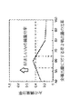
本発明者らが鋭意検討した結果、前記第1噴出量と前記第2噴出量の和に対する前記第2噴出量が0.55以上0.65以下である場合に、特に、前記加工部分周辺のシールドガスの濃度低下をより効果的に抑制できることを見出した。図5は、このことを示すグラフであり、本実施例のシールドガス供給装置3における好ましいシールドガスの噴出量の比率を表すグラフである。詳細には、リング状部8の内側13のシールドガス分布をCFD(Computational Fluid Dynamics)解析により計算した結果を表している。図5で表されるように、全噴出量に対する第2噴出量の比率が0.55以上0.65以下である場合に、好ましいシールドガス(Ar)の質量分布である0.4以上になっている。
このため、本実施例のシールドガス供給装置3は、特に、前記加工部分周辺のシールドガスの濃度低下をより効果的に抑制できる構成になっている。
本発明者らが鋭意検討した結果、前記第1噴出量と前記第2噴出量の和に対する前記第2噴出量が0.55以上0.65以下である場合に、特に、前記加工部分周辺のシールドガスの濃度低下をより効果的に抑制できることを見出した。図5は、このことを示すグラフであり、本実施例のシールドガス供給装置3における好ましいシールドガスの噴出量の比率を表すグラフである。詳細には、リング状部8の内側13のシールドガス分布をCFD(Computational Fluid Dynamics)解析により計算した結果を表している。図5で表されるように、全噴出量に対する第2噴出量の比率が0.55以上0.65以下である場合に、好ましいシールドガス(Ar)の質量分布である0.4以上になっている。
このため、本実施例のシールドガス供給装置3は、特に、前記加工部分周辺のシールドガスの濃度低下をより効果的に抑制できる構成になっている。
[実施例2](図6~図7)
次に、実施例2の記録装置について、添付図面を参照して詳細に説明する。
図6は、本実施例のレーザー加工機1のシールドガス供給装置3を表す概略斜視図である。また、図7は、本実施例のレーザー加工機1のシールドガス供給装置3の要部であるリング状部8の概略断面図である。なお、図6から図7は、被加工面が水平方向の被加工材Mに対して鉛直上方向からレーザーLを照射して加工を行う際におけるシールドガス供給装置3を表している。ここで、上記実施例と共通する構成部材は同じ符号で示しており、詳細な説明は省略する。
なお、本実施例のシールドガス供給装置3は、先端を封止した管上の部材をリング状に曲げ加工して構成されたものではなく、リング状に構成された部材に管状部15を設ける加工を別途行うことによって構成されたものである。しかしながら、穴部12の位置やシールドガスの噴出方向や噴出量は、実施例1のシールドガス供給装置3と同様である。
次に、実施例2の記録装置について、添付図面を参照して詳細に説明する。
図6は、本実施例のレーザー加工機1のシールドガス供給装置3を表す概略斜視図である。また、図7は、本実施例のレーザー加工機1のシールドガス供給装置3の要部であるリング状部8の概略断面図である。なお、図6から図7は、被加工面が水平方向の被加工材Mに対して鉛直上方向からレーザーLを照射して加工を行う際におけるシールドガス供給装置3を表している。ここで、上記実施例と共通する構成部材は同じ符号で示しており、詳細な説明は省略する。
なお、本実施例のシールドガス供給装置3は、先端を封止した管上の部材をリング状に曲げ加工して構成されたものではなく、リング状に構成された部材に管状部15を設ける加工を別途行うことによって構成されたものである。しかしながら、穴部12の位置やシールドガスの噴出方向や噴出量は、実施例1のシールドガス供給装置3と同様である。
本実施例のシールドガス供給装置3は、実施例1のシールドガス供給装置3に対して上記のような構成上の違いはあるものの、実施例1のシールドガス供給装置3と同様の特徴を有している。このため、レーザー加工機1でレーザー加工を行う際に、被加工材Mに効率よくシールドガスを噴出することができる構成になっている。
[実施例3](図8)
次に、実施例2の記録装置について、添付図面を参照して詳細に説明する。
図8は、本実施例のレーザー加工機1のシールドガス供給装置3を表す概略斜視図である。なお、図8は、被加工面が水平方向の被加工材Mに対して鉛直上方向からレーザーLを照射して加工を行う際におけるシールドガス供給装置3を表している。ここで、上記実施例と共通する構成部材は同じ符号で示しており、詳細な説明は省略する。
なお、本実施例のシールドガス供給装置3は、リング状部8をその周方向において囲む壁部16を備えること以外は実施例1の記録装置1と同様の構成である。
次に、実施例2の記録装置について、添付図面を参照して詳細に説明する。
図8は、本実施例のレーザー加工機1のシールドガス供給装置3を表す概略斜視図である。なお、図8は、被加工面が水平方向の被加工材Mに対して鉛直上方向からレーザーLを照射して加工を行う際におけるシールドガス供給装置3を表している。ここで、上記実施例と共通する構成部材は同じ符号で示しており、詳細な説明は省略する。
なお、本実施例のシールドガス供給装置3は、リング状部8をその周方向において囲む壁部16を備えること以外は実施例1の記録装置1と同様の構成である。
上記のように、本実施例のシールドガス供給装置3は、リング状部8をリング状部8の周方向において囲む壁部16を備えている。このため、壁部16により前記加工部分周辺から前記シールドガスが逃げることを抑制でき、前記加工部分周辺のシールドガスの濃度低下をより効果的に抑制できる構成になっている。
なお、壁部16の高さは、レーザー加工の障害にならない高さであれば、なるべく高い方がよい。シールドガスが逃げることを効果的に抑制できるためである。
なお、壁部16の高さは、レーザー加工の障害にならない高さであれば、なるべく高い方がよい。シールドガスが逃げることを効果的に抑制できるためである。
[その他の実施例]
なお、上記実施例は、いずれも、管状部15が2段の構成であったが、3段以上の構成としてもよい。
また、上記実施例は、いずれも、リング状部8が真円形の構成であったが、楕円形や多角形の構成としてもよい。
なお、上記実施例は、いずれも、管状部15が2段の構成であったが、3段以上の構成としてもよい。
また、上記実施例は、いずれも、リング状部8が真円形の構成であったが、楕円形や多角形の構成としてもよい。
Claims (19)
- レーザー加工機から被加工材に照射されるレーザーを囲む位置に配置されるリング状部と、
前記リング状部にシールドガスを供給する供給管と、を備え、
前記リング状部は、該リング状部の周方向に、前記供給管から供給される前記シールドガスの移動経路を有し、
前記移動経路は、
前記被加工材に対して多段に配置され、
前記リング状部の内周部分に、前記周方向に旋回流を形成するように前記シールドガスを噴出する、孔部が設けられている
ことを特徴とするレーザー加工機のシールドガス供給装置。 - 請求項1に記載のシールドガス供給装置において、
前記孔部は、前記リング状部の中心に向かう方向から前記シールドガスの前記移動経路における移動方向の下流側に傾斜した方向に該シールドガスを噴出することを特徴とするレーザー加工機のシールドガス供給装置。 - 請求項1に記載のシールドガス供給装置において、
多段に配置される前記移動経路各々に設けられる前記孔部は、前記周方向において同じ位置に設けられていることを特徴とするレーザー加工機のシールドガス供給装置。 - 請求項2に記載のシールドガス供給装置において、
多段に配置される前記移動経路各々に設けられる前記孔部は、前記周方向において同じ位置に設けられていることを特徴とするレーザー加工機のシールドガス供給装置。 - 請求項1に記載のシールドガス供給装置において、
前記リング状部を前記周方向において囲む壁部を備えることを特徴とするレーザー加工機のシールドガス供給装置。 - 請求項2に記載のシールドガス供給装置において、
前記リング状部を前記周方向において囲む壁部を備えることを特徴とするレーザー加工機のシールドガス供給装置。 - 請求項1に記載のシールドガス供給装置において、
多段に配置される前記移動経路のうちの前記被加工材の近くに配置される第1移動経路に設けられる前記孔部から噴出する前記シールドガスの第1噴出量は、多段に配置される前記移動経路のうちの前記被加工材から遠くに配置される第2移動経路に設けられる前記孔部から噴出する前記シールドガスの第2噴出量よりも少ないことを特徴とするレーザー加工機のシールドガス供給装置。 - 請求項2に記載のシールドガス供給装置において、
多段に配置される前記移動経路のうちの前記被加工材の近くに配置される第1移動経路に設けられる前記孔部から噴出する前記シールドガスの第1噴出量は、多段に配置される前記移動経路のうちの前記被加工材から遠くに配置される第2移動経路に設けられる前記孔部から噴出する前記シールドガスの第2噴出量よりも少ないことを特徴とするレーザー加工機のシールドガス供給装置。 - 請求項7に記載のシールドガス供給装置において、
前記第1噴出量と前記第2噴出量の和に対する前記第2噴出量は、0.55以上0.65以下であることを特徴とするレーザー加工機のシールドガス供給装置。 - 請求項8に記載のシールドガス供給装置において、
前記第1噴出量と前記第2噴出量の和に対する前記第2噴出量は、0.55以上0.65以下であることを特徴とするレーザー加工機のシールドガス供給装置。 - 請求項1に記載のシールドガス供給装置において、
多段に配置される前記移動経路のうちの前記被加工材の近くに配置される第1移動経路に設けられる前記孔部から噴出する前記シールドガスの前記リング状部の中心に向かう方向に対する前記傾斜した方向の第1傾斜角は、多段に配置される前記移動経路のうちの前記被加工材から遠くに配置される第2移動経路に設けられる前記孔部から噴出する前記シールドガスの前記リング状部の中心に向かう方向に対する前記傾斜した方向の第2傾斜角以下であることを特徴とするレーザー加工機のシールドガス供給装置。 - 請求項2に記載のシールドガス供給装置において、
多段に配置される前記移動経路のうちの前記被加工材の近くに配置される第1移動経路に設けられる前記孔部から噴出する前記シールドガスの前記リング状部の中心に向かう方向に対する前記傾斜した方向の第1傾斜角は、多段に配置される前記移動経路のうちの前記被加工材から遠くに配置される第2移動経路に設けられる前記孔部から噴出する前記シールドガスの前記リング状部の中心に向かう方向に対する前記傾斜した方向の第2傾斜角以下であることを特徴とするレーザー加工機のシールドガス供給装置。 - 請求項11に記載のシールドガス供給装置において、
前記第1傾斜角は5.625°以上7.5°以下であり、前記第2傾斜角は7.5°以上15°以下であることを特徴とするレーザー加工機のシールドガス供給装置。 - 請求項12に記載のシールドガス供給装置において、
前記第1傾斜角は5.625°以上7.5°以下であり、前記第2傾斜角は7.5°以上15°以下であることを特徴とするレーザー加工機のシールドガス供給装置。 - 請求項1に記載のレーザー加工機のシールドガス供給装置と、
前記レーザーを照射するレーザー照射部と、
を備えることを特徴とするレーザー加工機。 - 請求項2に記載のレーザー加工機のシールドガス供給装置と、
前記レーザーを照射するレーザー照射部と、
を備えることを特徴とするレーザー加工機。 - 請求項3に記載のレーザー加工機のシールドガス供給装置と、
前記レーザーを照射するレーザー照射部と、
を備えることを特徴とするレーザー加工機。 - 請求項5に記載のレーザー加工機のシールドガス供給装置と、
前記レーザーを照射するレーザー照射部と、
を備えることを特徴とするレーザー加工機。 - 請求項7に記載のレーザー加工機のシールドガス供給装置と、
前記レーザーを照射するレーザー照射部と、
を備えることを特徴とするレーザー加工機。
Applications Claiming Priority (2)
| Application Number | Priority Date | Filing Date | Title |
|---|---|---|---|
| JP2014-017227 | 2014-01-31 | ||
| JP2014017227A JP5645095B1 (ja) | 2014-01-31 | 2014-01-31 | レーザー加工機のシールドガス供給装置及びレーザー加工機 |
Publications (1)
| Publication Number | Publication Date |
|---|---|
| WO2015114853A1 true WO2015114853A1 (ja) | 2015-08-06 |
Family
ID=52139216
Family Applications (1)
| Application Number | Title | Priority Date | Filing Date |
|---|---|---|---|
| PCT/JP2014/068413 Ceased WO2015114853A1 (ja) | 2014-01-31 | 2014-07-10 | レーザー加工機のシールドガス供給装置及びレーザー加工機 |
Country Status (2)
| Country | Link |
|---|---|
| JP (1) | JP5645095B1 (ja) |
| WO (1) | WO2015114853A1 (ja) |
Cited By (2)
| Publication number | Priority date | Publication date | Assignee | Title |
|---|---|---|---|---|
| CN114632947A (zh) * | 2022-03-01 | 2022-06-17 | 中山职业技术学院 | 一种wc硬质合金材料的slm成型方法 |
| CN117047270A (zh) * | 2023-07-28 | 2023-11-14 | 中国航发动力股份有限公司 | 接触保护工装及航空发动机燃油喷嘴的激光焊保护方法 |
Citations (4)
| Publication number | Priority date | Publication date | Assignee | Title |
|---|---|---|---|---|
| JPH01503612A (ja) * | 1986-06-23 | 1989-12-07 | ユニバーシティ・オブ・テネシー・リサーチ・コーポレーション | レーザにより、持続されたプラズマトーチ及び該トーチの使用方法 |
| JP2000202678A (ja) * | 1999-01-12 | 2000-07-25 | Nippon Steel Corp | レ―ザ切断用ノズル及びレ―ザ切断装置 |
| JP2007216290A (ja) * | 2006-02-20 | 2007-08-30 | Daihen Corp | レーザトーチ |
| JP2009006350A (ja) * | 2007-06-27 | 2009-01-15 | Sony Corp | レーザ加工装置とその加工方法、デブリ回収機構とその回収方法、並びに表示パネルの製造方法 |
-
2014
- 2014-01-31 JP JP2014017227A patent/JP5645095B1/ja not_active Expired - Fee Related
- 2014-07-10 WO PCT/JP2014/068413 patent/WO2015114853A1/ja not_active Ceased
Patent Citations (4)
| Publication number | Priority date | Publication date | Assignee | Title |
|---|---|---|---|---|
| JPH01503612A (ja) * | 1986-06-23 | 1989-12-07 | ユニバーシティ・オブ・テネシー・リサーチ・コーポレーション | レーザにより、持続されたプラズマトーチ及び該トーチの使用方法 |
| JP2000202678A (ja) * | 1999-01-12 | 2000-07-25 | Nippon Steel Corp | レ―ザ切断用ノズル及びレ―ザ切断装置 |
| JP2007216290A (ja) * | 2006-02-20 | 2007-08-30 | Daihen Corp | レーザトーチ |
| JP2009006350A (ja) * | 2007-06-27 | 2009-01-15 | Sony Corp | レーザ加工装置とその加工方法、デブリ回収機構とその回収方法、並びに表示パネルの製造方法 |
Cited By (2)
| Publication number | Priority date | Publication date | Assignee | Title |
|---|---|---|---|---|
| CN114632947A (zh) * | 2022-03-01 | 2022-06-17 | 中山职业技术学院 | 一种wc硬质合金材料的slm成型方法 |
| CN117047270A (zh) * | 2023-07-28 | 2023-11-14 | 中国航发动力股份有限公司 | 接触保护工装及航空发动机燃油喷嘴的激光焊保护方法 |
Also Published As
| Publication number | Publication date |
|---|---|
| JP5645095B1 (ja) | 2014-12-24 |
| JP2015142932A (ja) | 2015-08-06 |
Similar Documents
| Publication | Publication Date | Title |
|---|---|---|
| CN109153096B (zh) | 激光焊接装置及激光焊接方法 | |
| CN102672349B (zh) | 激光焊接设备 | |
| US9533373B2 (en) | Powder overlay nozzle | |
| CN101291773B (zh) | 具有金属蒸气毛细管形成控制的激光束焊接方法 | |
| JP5364517B2 (ja) | プラズマトーチおよびプラズマアーク溶接方法 | |
| US10654129B2 (en) | Laser processing heads with a cross-jet nozzle | |
| JP2013075308A (ja) | パウダ供給ノズルおよび肉盛溶接方法 | |
| JP6148878B2 (ja) | レーザ加工機の同軸ノズル | |
| JP6002586B2 (ja) | ノズル及び粉塵の付着防止方法 | |
| JP2005219060A (ja) | 粉末金属肉盛ノズル | |
| JP6167055B2 (ja) | レーザノズル、レーザ加工装置、及びレーザ加工方法 | |
| JP5039757B2 (ja) | レーザ加工装置におけるレーザ加工ヘッド | |
| JP6174891B2 (ja) | レーザ加工ヘッド | |
| JP6372797B2 (ja) | レーザ溶接用ノズル | |
| JP2016074017A (ja) | 溶接装置およびノズル装置 | |
| JP2015157297A (ja) | 溶接ヘッド、レーザ溶接装置、及び溶接ヘッド用のガスノズル | |
| JP6035088B2 (ja) | レーザ加工ヘッド用ノズル | |
| JP2019093438A (ja) | レーザノズル | |
| JP2010234373A (ja) | レーザ加工用ノズル及びレーザ加工装置 | |
| JP5645095B1 (ja) | レーザー加工機のシールドガス供給装置及びレーザー加工機 | |
| JP4555743B2 (ja) | レーザ加工ヘッド | |
| JPWO2020213051A1 (ja) | 金属造形用シールドガスノズル、及びレーザ金属造形装置 | |
| JP2007216290A (ja) | レーザトーチ | |
| CN102189319A (zh) | 等离子焊炬及采用等离子焊炬的焊接方法 | |
| JP5412813B2 (ja) | レーザ溶接シールド方法及びシールドガス供給ノズル及びレーザ溶接シールド装置 |
Legal Events
| Date | Code | Title | Description |
|---|---|---|---|
| 121 | Ep: the epo has been informed by wipo that ep was designated in this application |
Ref document number: 14880585 Country of ref document: EP Kind code of ref document: A1 |
|
| NENP | Non-entry into the national phase |
Ref country code: DE |
|
| 122 | Ep: pct application non-entry in european phase |
Ref document number: 14880585 Country of ref document: EP Kind code of ref document: A1 |