WO2015111448A1 - 副変速機構付き変速機 - Google Patents
副変速機構付き変速機 Download PDFInfo
- Publication number
- WO2015111448A1 WO2015111448A1 PCT/JP2015/050480 JP2015050480W WO2015111448A1 WO 2015111448 A1 WO2015111448 A1 WO 2015111448A1 JP 2015050480 W JP2015050480 W JP 2015050480W WO 2015111448 A1 WO2015111448 A1 WO 2015111448A1
- Authority
- WO
- WIPO (PCT)
- Prior art keywords
- shift
- transmission
- sub
- main
- shaft
- Prior art date
- Legal status (The legal status is an assumption and is not a legal conclusion. Google has not performed a legal analysis and makes no representation as to the accuracy of the status listed.)
- Ceased
Links
Images



Classifications
-
- F—MECHANICAL ENGINEERING; LIGHTING; HEATING; WEAPONS; BLASTING
- F16—ENGINEERING ELEMENTS AND UNITS; GENERAL MEASURES FOR PRODUCING AND MAINTAINING EFFECTIVE FUNCTIONING OF MACHINES OR INSTALLATIONS; THERMAL INSULATION IN GENERAL
- F16H—GEARING
- F16H63/00—Control outputs from the control unit to change-speed- or reversing-gearings for conveying rotary motion or to other devices than the final output mechanism
- F16H63/02—Final output mechanisms therefor; Actuating means for the final output mechanisms
- F16H63/30—Constructional features of the final output mechanisms
- F16H63/3013—Constructional features of the final output mechanisms the final output mechanism being characterised by linkages converting movement, e.g. into opposite direction by a pivoting lever linking two shift rods
-
- F—MECHANICAL ENGINEERING; LIGHTING; HEATING; WEAPONS; BLASTING
- F16—ENGINEERING ELEMENTS AND UNITS; GENERAL MEASURES FOR PRODUCING AND MAINTAINING EFFECTIVE FUNCTIONING OF MACHINES OR INSTALLATIONS; THERMAL INSULATION IN GENERAL
- F16H—GEARING
- F16H61/00—Control functions within control units of change-speed- or reversing-gearings for conveying rotary motion ; Control of exclusively fluid gearing, friction gearing, gearings with endless flexible members or other particular types of gearing
- F16H61/70—Control functions within control units of change-speed- or reversing-gearings for conveying rotary motion ; Control of exclusively fluid gearing, friction gearing, gearings with endless flexible members or other particular types of gearing specially adapted for change-speed gearing in group arrangement, i.e. with separate change-speed gear trains arranged in series, e.g. range or overdrive-type gearing arrangements
Definitions
- the present invention relates to a transmission with a sub-transmission mechanism, and more particularly, to a transmission with a sub-transmission mechanism that can perform synchronous transmission more reliably than before.
- multi-stage transmissions with 12 or 16 gears are employed.
- a method of taking a multi-stage by combining a sub-transmission called a splitter and a main transmission is employed instead of simply increasing the number of gear stages.
- Patent Document 1 Japanese Patent Application Laid-Open No. 2013-137079
- the inventor makes the sub-transmission and the main transmission four by operating a single operation lever.
- a transmission with a sub-transmission mechanism has been proposed in which gears can be simultaneously shifted by being synchronized via an interlocking mechanism including a joint link mechanism.
- This interlocking mechanism has a function to rotate the output in one direction on the main transmission side regardless of the rotation direction of the input when the input is performed in the shift direction on the sub transmission side from the neutral position by the operation lever. is doing.
- An object of the present invention is to provide a transmission with a sub-transmission mechanism that can perform synchronous gear shifting more reliably than before.
- a transmission with a sub-transmission mechanism of the present invention that achieves the above object is a transmission with a sub-transmission mechanism that simultaneously shifts the main transmission mechanism and the sub-transmission mechanism by operating the operation lever in the select direction and the shift direction.
- a sub-shifting shift shaft that extends in the select direction on the side of the sub-transmission mechanism and rotates in response to an operation of the operating lever in the shift direction; and an upper end portion of the sub-transmission shaft is rotatable.
- a sub-shifting shift lever that is supported and connected via an elastic member and extends downward, and a sub-shift that is disposed below the sub-transmission shaft and engages with a lower end portion of the sub-transmission shift lever.
- a shift lever for main shift that moves in the select direction by operating the select lever in the select direction; and a lower end portion of the shift lever for main shift that is arranged in parallel in the select direction below the main shift shaft.
- the sub-transmission shift shaft and the main transmission shift shaft are provided with a protruding portion provided upright on one arm.
- the guide groove is connected by an interlocking mechanism that engages with a guide groove provided on the arm of the arm, and the guide groove is formed in a substantially v-shape that protrudes toward the shift shaft to which the one arm is connected.
- a pressing means for pressing the projection located at the bent portion of the guide groove toward the groove wall of the guide groove, and the shift lever for sub-transmission is operated by operating the operating lever in the shift direction. Regardless of the direction of rotation of the shaft, the rotational force transmitted to the main transmission shift shaft through the interlocking mechanism is converted into one direction by the interlocking mechanism, so that the main transmission shift lever is moved in one direction.
- the sub-transmission mechanism-side synchronization mechanism and the main transmission mechanism-side synchronization mechanism start synchronous coupling simultaneously, so that the rotational force of the sub-transmission shift shaft is transmitted via the elastic member to the sub-transmission mechanism. It is transmitted to a shift lever for shifting.
- the auxiliary transmission shift shaft on the auxiliary transmission mechanism side and the main transmission shift shaft on the main transmission mechanism side are connected using the interlock mechanism as described above, thus, it is possible to perform synchronous shift more reliably.
- FIG. 1 is a skeleton diagram of a transmission with an auxiliary transmission mechanism according to an embodiment of the present invention.
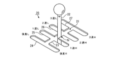
- FIG. 2 is a schematic perspective view showing a shift operation device for operating the transmission with the auxiliary transmission mechanism according to the embodiment of the present invention.
- FIG. 3 is a top view showing the configuration of the transmission with the auxiliary transmission mechanism according to the embodiment of the present invention.
- FIG. 4 is a configuration diagram from the select direction of the interlocking mechanism in the transmission with the auxiliary transmission mechanism according to the embodiment of the present invention.
- FIG. 1 to 4 show a transmission with an auxiliary transmission mechanism according to an embodiment of the present invention.
- “for splitter” means “for auxiliary transmission”
- “for main” means “for main transmission”.
- the transmission with a sub-transmission mechanism (hereinafter referred to as “transmission”) 1 includes a splitter-type sub-transmission mechanism 2 disposed on the input side and a main transmission disposed on the output side.
- the mechanism 3 is mainly configured.
- an input shaft 4 for transmitting the output of an engine (not shown) is installed on the auxiliary transmission mechanism 2 side.
- a main shaft 5 is disposed on the main transmission mechanism 3 side so as to be coaxial with the input shaft 4.
- the auxiliary transmission mechanism 2 and the main transmission mechanism 3 are provided with a counter shaft 6 that extends in parallel to the input shaft 4 and the main shaft 5.
- the splitter low speed gear 7 is provided on the input shaft 4 so as to be relatively rotatable.
- the main shaft 5 is provided with a splitter high speed gear 8, a main third speed gear 9, a main second speed gear 10, a main first speed gear 11, and a main reverse gear 12 in order from the input side so as to be relatively rotatable.
- the counter shaft 6 includes a counter low-speed gear 13 that meshes with the splitter low-speed gear 7, a counter high-speed gear 14 that meshes with the splitter high-speed gear 8, a counter third-speed gear 15 that meshes with the main third-speed gear 9, and a main second-speed gear.
- a counter second speed gear 16 that meshes with 10, a counter first speed gear 17 that meshes with the main first speed gear 11, and a counter reverse gear 19 that meshes with the main reverse gear 12 via an idler gear 18 are fixed.
- the transmission 1 is configured to selectively move the splitter gears 7 and 8 and selectively switch the main gears 9 to 12 to provide six forward speeds (1st speed L to 3rd speed H) and 2 reverse speeds ( The rearward shift L and the reverse shift H) are configured to be possible.
- the shift operation device 20 of the transmission 1 has a plurality of H-type gates 21 and their H-type gates 21 so that the speed change between the sub-transmission mechanism 2 and the main transmission mechanism 3 can be operated simultaneously. And an operation lever 22 for moving (stroke).
- a select path 23 is provided in the select direction of the H-shaped gate 21, and a neutral position N corresponding to the neutral mode is set at the center thereof.
- a neutral position N corresponding to the neutral mode is set at the center thereof.
- four shift paths 24 to 27 orthogonal to the select path 23 are provided. Further, at the end portions of the four shift paths 24 to 27 corresponding to the end of the stroke of the operation lever 22, the above-described six forward speeds (1st speed L to 3rd speed H) and 2 reverse speeds (reverse L, reverse) Shift positions corresponding to H) are respectively set.
- the shift operating device 20 is connected to the shift mechanism of the subtransmission mechanism 2 when the operation lever 22 is operated in the shift direction, and is connected to the select mechanism of the main transmission mechanism 3 when the operation lever 22 is operated in the select direction. It is configured to be.
- the transmission mechanism 30 of the transmission 1 includes a first shift shaft 31 that extends in the shift direction, a second shift shaft 32 that extends parallel to the first shift shaft 31, and a sub-transmission.
- Four shafts consisting of a splitter shift shaft 33 extending in the select direction on the mechanism 2 side, a main shift shaft 34 extending in the select direction on the main transmission mechanism 3 side, and a main R / 1 speed connecting mechanism 35 and a main 2/3 speed connection mechanism (not shown).
- a splitter shift lever 36 is rotatably attached to the splitter shift shaft 33, and a spring 38 is interposed between the splitter shift lever 36 and the annular flange 37.
- a splitter shift block 39 is disposed below the splitter shift shaft 33. The lower end of the splitter shift lever 36 is formed at the center of the splitter shift block 39, as shown in FIG. Engaged with the recess.
- the upper end of the main shift lever 40 is spline fitted to the main shift shaft 34. For this reason, the main shift lever 40 rotates integrally with the main shift shaft 34, while being movable in the axial direction (select direction) of the main shift shaft 34. Further, below the main shift shaft 34, four main shift blocks 41 to 44 arranged in parallel in the select direction are arranged. As shown in FIG. 4, the lower end portion of the main shift lever 40 is The main shift blocks 41 to 44 are engaged with recesses formed in the center.
- a splitter shift fork 45 is provided on the first shift shaft 31 so as to be movable in the axial direction, and a main 2/3 speed shift fork 46 is fixed to the first shift shaft 31.
- a main R / 1 speed shift fork 47 is fixed to the second shift shaft 32.
- the main R / 1 speed connecting mechanism 35 includes a connecting member 48 for connecting and fixing the main reverse shift block 41 and the second shift shaft 32, a rod 49 fixed to the main first speed shift block 42, and a central portion. And a reversing lever 50 that can rotate around the fulcrum.
- the reversing lever 50 has one end connected to the rod 49 and the other end hinged to the second shift shaft 32.
- the connecting member 48 connects and fixes the main 2 speed shift block 43 and the first shift shaft 31, and the reversing lever 50 is connected to the main 3 speed shift block 44. Except for being hingedly connected to the fixed rod 49 and the first shift shaft 41, the main R / 1 speed connecting mechanism 35 is configured in substantially the same manner.
- the splitter shift lever 36 is also rotated in the same direction.
- the shift block 39 moves to the left (X direction shown in FIG. 4).
- the shift fork 45 for the splitter moves to the left toward the splitter low-speed gear 7 and contacts the spline teeth (not shown) of the corresponding sleeve and the dog teeth (not shown) of the block ring.
- the main shift lever 40 is moved to the main shift shaft 34. Move along the select direction. As a result, the lower end portion of the main shift lever 40 engages with any one of the concave portions of the main shift blocks 41 to 44 corresponding to the selected arbitrary shift position.
- the main shift lever 40 rotates counterclockwise (the F direction shown in FIG. 4) by operating the operation lever 22 in the select direction
- the main first speed shift block 42 moves to the right (the Y direction shown in FIG. 4). Move to).
- the rightward moving force of the main first speed shift block 42 is converted to the leftward by the rotation operation of the reversing lever 50 and transmitted to the second shift shaft 32.
- the main R / 1-speed shift fork 47 moves to the left toward the main first-speed gear 11 along with the second shift shaft 32, and the corresponding spline teeth (not shown) and blocks of the sleeve Contact the dog teeth (not shown) of the ring.
- one end of the splitter shift shaft 33 and the main shift shaft 34 is fixed to the splitter shift shaft 33, and a cylindrical protrusion 60 is erected on the other end. It is connected by an interlocking mechanism 64 comprising a splitter interlocking arm 61 and a main interlocking arm 63 having a guide groove 62 with one end fixed to the main shift shaft 34 and the other end being engaged with the projection 60. ing. It is preferable that the outer diameter of the protrusion 60 and the groove diameter of the guide groove 62 are substantially the same.
- the guide groove 62 is formed in a substantially ⁇ shape that is convex toward the splitter shift shaft 33 side, and a bent portion 62 a thereof corresponds to the neutral position N.
- the main interlocking arm 63 is provided with a groove wall (edge) of the guide groove 62 so that the protrusion 60 does not rattle when the protrusion 60 is positioned at the bent portion 62a where the shape of the guide groove 62 is discontinuous.
- the pressing means 65 is provided to press the portion.
- the pressing means 65 includes a spring member 66 having one end fixed on the main interlocking arm 63 and a spherical member 67 attached to the other end of the spring member 66.
- the guide groove 62 is pressed toward the groove wall.
- the projecting portion 60 causes the guide groove 62 to transmit the rotational force in the left and right directions (directions C and D shown in FIG. 4) transmitted from the splitter shift shaft 33 to the splitter interlocking arm 61.
- the main interlocking arm 63 is converted to a leftward rotational force (E direction shown in FIG. 4) and the main shift shaft 34 is always rotated leftward (F direction shown in FIG. 4).
- the pressing means 65 that presses the projection 60 at the bent portion 62a where the guide groove 62 is discontinuous, the projection 60 is not rattled, so the neutral position N can be accurately determined.
- the number of shift stages in the transmission 1 of the present invention is not limited to the above-described six forward speeds (1st speed L to 3rd speed H), but 4 forward speeds (1st speed L to 2nd speed H) or 8 forward speeds ( 1st speed L to 4th speed H), or more stages may be used.
- the transmission 1 is not limited to a manual transmission, and the present invention can also be applied to a mechanical manual transmission (AMT) in which a shift operation and a selection operation are automated by an actuator or the like.
- AMT mechanical manual transmission
Landscapes
- Engineering & Computer Science (AREA)
- General Engineering & Computer Science (AREA)
- Mechanical Engineering (AREA)
- Gear-Shifting Mechanisms (AREA)
Abstract
副変速機構付き変速機(1)におけるスプリッタ用シフトシャフト(33)とメイン用シフトシャフト(34)とを、一端部がスプリッタ用シフトシャフト(33)に固定され、かつ他端部に突起部(60)を有するスプリッタ用連動アーム(61)と、一端部がメイン用シフトシャフト(34)に固定され、かつ他端部に突起部(60)が係合するガイド溝(62)を有するメイン用連動アーム(63)とからなる連動機構(64)により連結し、ガイド溝(62)をスプリッタ用シフトシャフト(33)側に向けて凸となる略ν字状に形成するとともに、メイン用連動アーム(63)にガイド溝(62)の屈曲部(62a)に位置した突起部(60)を縁部に押圧する押圧手段(65)を設ける。
Description
本発明は副変速機構付き変速機に関し、更に詳しくは、従来よりも確実に同期変速することができる副変速機構付き変速機に関する。
近年の大型車両においては、ギア段の数が12段や16段といった多段変速機を採用している。このような多段変速機では、ギア段を単純に増やして多段化するのではなく、スプリッタと呼ばれる副変速機と主変速機との組み合わせで多段化する方法が取られている。
これらの副変速機及び主変速機に対しては、それぞれ個別の変速機構が必要となる。そのため、車両の走行状態に応じた最適な変速比を得るには、両方の変速機の操作機構を同時に操作しなければならないので、ドライバーの大きな負担となっていた。
これに対して発明者は、日本出願の特開2013-137079号公報(特許文献1)に記載されているように、単一の操作レバーの操作により、副変速機と主変速機とを四節リンク機構からなる連動機構を介して同期させることで同時に変速できるようにした副変速機構付き変速機を提案している。この連動機構は、操作レバーによりニュートラル位置から副変速機側においてシフト方向に入力が行われた場合に、その入力の回転方向によらず主変速機側において出力を一方向に回転させる機能を有している。
上記の四節リンク機構においては、入力[x]と出力[y]の作動角度の関係は二次曲線になることが知られている。そのため、二次曲線状の出力[y]の傾きが大きくなる操作レバーのストロークの終端部においては、ストロークスピードが増加する分だけ|y/x|に比例する操作力が低下してしまうので、主変速機においてギア同士が噛合しにくくなるという問題がある。
このような問題を解決するため、発明者は、更に研究開発を鋭意進めた結果、本発明を完成するに至ったものである。
本発明の目的は、従来よりも確実に同期変速することができる副変速機構付き変速機を提供することにある。
上記の目的を達成する本発明の副変速機構付き変速機は、操作レバーのセレクト方向及びシフト方向への操作により主変速機構と副変速機構とを同時に変速する副変速機構付き変速機であって、前記副変速機構側のセレクト方向に延在して設けられて前記操作レバーのシフト方向への操作に応じて回転する副変速用シフトシャフトと、前記副変速用シャフトに上端部を回転自在に支持され、かつ弾性部材を介して接続された下方に延出する副変速用シフトレバーと、前記副変速用シャフトの下方に配置されて前記副変速用シフトレバーの下端部と係合する副変速用シフトブロックと、前記主変速機構側のセレクト方向に延在して設けられた回転自在な主変速用シフトシャフトと、前記主変速用シャフトから下方に延出して設けられるとともに、前記操作レバーのセレクト方向への操作によりセレクト方向に移動する主変速用シフトレバーと、前記主変速用シャフトの下方にセレクト方向に並列して配置されて前記主変速用シフトレバーの下端部と係合する複数の主変速用シフトブロックとを備えた副変速機構付き変速機において、前記副変速用シフトシャフトと前記主変速用シフトシャフトとを、一方のアームに立設された突起部が他方のアームに設けられたガイド溝に係合する連動機構により連結するとともに、前記ガイド溝を前記一方のアームが接続するシフトシャフト側に向けて凸となる略ν字状に形成し、前記ガイド溝の屈曲部に位置した前記突起部を該ガイド溝の溝壁へ向けて押圧する押圧手段を設け、前記操作レバーのシフト方向への操作により前記副変速用シフトシャフトが何れの方向に回転されても、前記連動機構を介して前記主変速用シフトシャフトに伝達される回転力が該連動機構により一方向に変換されて前記主変速用シフトレバーを一方向にのみ回転させ、前記副変速機構側のシンクロ機構と前記主変速機構側のシンクロ機構とが同時に同期結合を開始するように、前記副変速用シフトシャフトの回転力が前記弾性部材を介して前記副変速用シフトレバーに伝達されることを特徴とするものである。
本発明の副変速機構付き変速機によれば、上記のような連動機構を用いて副変速機構側の副変速用シフトシャフトと主変速機構側の主変速用シフトシャフトとを連結したので、従来よりも確実に同期変速することができる。
以下に、本発明の実施の形態について、図面を参照して説明する。図1~4は、本発明の実施形態からなる副変速機構付き変速機を示す。なお、以下の説明においては、「スプリッタ用」とは「副変速用」を、「メイン用」とは「主変速用」をそれぞれ意味するものとする。
この副変速機構付き変速機(以下、「変速機」という。)1は、図1に示すように、入力側に配置されたスプリッタ式の副変速機構2と、出力側に配置された主変速機構3とから主に構成されている。
副変速機構2側には、エンジン(図示せず)の出力が伝達されるインプットシャフト4が設置されている。また、主変速機構3側には、インプットシャフト4と同軸になるようにメインシャフト5が配置されている。更に、副変速機構2及び主変速機構3には、これらのインプットシャフト4及びメインシャフト5に平行に延びるカウンタシャフト6が配置されている。
インプットシャフト4には、スプリッタ低速ギヤ7が相対回転可能に設けられている。また、メインシャフト5には、入力側から順にスプリッタ高速ギヤ8、メイン3速ギヤ9、メイン2速ギヤ10、メイン1速ギヤ11及びメイン後進ギヤ12がそれぞれ相対回転可能に設けられている。
また、カウンタシャフト6には、スプリッタ低速ギヤ7と噛合するカウンタ低速ギヤ13、スプリッタ高速ギヤ8と噛合するカウンタ高速ギヤ14、メイン3速ギヤ9と噛合するカウンタ3速ギヤ15、メイン2速ギヤ10と噛合するカウンタ2速ギヤ16、メイン1速ギヤ11と噛合するカウンタ1速ギヤ17、及びメイン後進ギヤ12とアイドラギヤ18を介して噛合するカウンタ後進ギヤ19がそれぞれ固定されている。
このように、変速機1は、スプリッタギヤ7、8の選択的な切り替えと、メインギヤ9~12の選択的な切り替えとにより、前進6段(1速L~3速H)及び後進2段(後進L、後進H)の変速が可能になるように構成されている。
図2に示すように、変速機1のシフト操作装置20は、副変速機構2と主変速機構3との変速を同時に操作できるように、複数のH型ゲート21と、それらのH型ゲート21を移動(ストローク)する操作レバー22とを有している。
H型ゲート21のセレクト方向にはセレクト経路23が設けられ、その中央にはニュートラルモードに対応するニュートラル位置Nが設定されている。また、H型ゲート21のシフト方向には、セレクト経路23と直交する4本のシフト経路24~27がそれぞれ設けられている。更に、操作レバー22のストロークの終端部に相当する4本のシフト経路24~27の端部には、上述した前進6段(1速L~3速H)及び後進2段(後進L、後進H)に対応するシフト位置がそれぞれ設定されている。
つまり、このシフト操作装置20は、操作レバー22をシフト方向に操作すると副変速機構2のシフト機構に接続される一方で、操作レバー22をセレクト方向に操作すると主変速機構3のセレクト機構に接続されるように構成されている。
図3に示すように、変速機1の変速機構30は、シフト方向に延在する第1シフトシャフト31と、この第1シフトシャフト31と平行に延在する第2シフトシャフト32と、副変速機構2側においてセレクト方向に延在するスプリッタ用シフトシャフト33と、主変速機構3側においてセレクト方向に延在するメイン用シフトシャフト34からなる4本のシャフト、並びにメインR/1速用接続機構35及びメイン2/3速用接続機構(図示せず)を備えている。
スプリッタ用シフトシャフト33には、スプリッタ用シフトレバー36が回転自在に取り付けられており、そのスプリッタ用シフトレバー36と環状フランジ37との間にはスプリング38が介挿されている。また、スプリッタ用シフトシャフト33の下方には、スプリッタ用シフトブロック39が配置されており、図4に示すように、スプリッタ用シフトレバー36の下端部が、スプリッタ用シフトブロック39の中央に形成された凹部と係合している。
メイン用シフトシャフト34には、メイン用シフトレバー40の上端部がスプライン嵌合している。そのため、メイン用シフトレバー40は、メイン用シフトシャフト34と一体に回転する一方で、メイン用シフトシャフト34の軸方向(セレクト方向)へ移動可能になっている。また、メイン用シフトシャフト34の下方には、セレクト方向に並列された4個のメイン用シフトブロック41~44が配置されており、図4に示すように、メイン用シフトレバー40の下端部が、それぞれのメイン用シフトブロック41~44の中央に形成された凹部と係合している。
第1シフトシャフト31には、スプリッタ用シフトフォーク45が軸方向に移動可能に設けられているとともに、メイン2/3速用シフトフォーク46が固定されている。また、第2シフトシャフト32には、メインR/1速用シフトフォーク47が固定されている。
メインR/1速用接続機構35は、メイン後進用シフトブロック41と第2シフトシャフト32とを接続固定する接続部材48と、メイン1速用シフトブロック42に固定されたロッド49と、中心部を支点に回転可能な反転レバー50とを備えている。この反転レバー50は、一端部がロッド49に、他端部が第2シフトシャフト32に、それぞれヒンジ連結されている。
なお、図示しないメイン2/3速用接続機構は、接続部材48がメイン2速用シフトブロック43と第1シフトシャフト31とを接続固定するとともに、反転レバー50がメイン3速用シフトブロック44に固定されたロッド49と第1シフトシャフト41とにヒンジ連結されることを除けば、メインR/1速用接続機構35と略同様に構成されている。
この変速機構30において、操作レバー22のシフト方向への操作により、副変速機構2のシフト機構がシフト動作(図3に示すX方向)されてスプリッタ用シフトシャフト33が回転すると、スプリッタ用シフトレバー36は環状フランジ37及びスプリング38を介して伝達される回転力により回転される。これにより、スプリッタ用シフトブロック39は、操作レバー22のシフト方向への操作に応じて左右方向(図4に示すX、Y方向)に移動する。
例えば、操作レバー22のシフト方向への操作により、スプリッタ用シフトシャフト33が時計回り(図4に示すA方向)に回転されると、スプリッタ用シフトレバー36も同方向へ回転して、スプリッタ用シフトブロック39が左方向(図4に示すX方向)に移動する。それに伴って、スプリッタ用シフトフォーク45がスプリッタ低速ギヤ7に向けて左方向へと移動して、対応するスリーブのスプライン歯(図示せず)とブロックリングのドグ歯(図示せず)とを接触させる。
また、変速機構30において、操作レバー22のセレクト方向への操作により、主変速機構3のセレクト機構がセレクト動作(図3に示すY方向)すると、メイン用シフトレバー40はメイン用シフトシャフト34に沿ってセレクト方向に移動する。これにより、メイン用シフトレバー40の下端部は、選択された任意のシフト位置に対応するメイン用シフトブロック41~44のいずれかの凹部と係合する。
例えば、操作レバー22のセレクト方向への操作により、メイン用シフトレバー40が左回り(図4に示すF方向)に回転すると、メイン1速用シフトブロック42が右方向(図4に示すY方向)へ移動する。そして、メイン1速用シフトブロック42の右方向の移動力は、反転レバー50の回転動作により左方向に変換されて第2シフトシャフト32へと伝達される。これにより、メインR/1速用シフトフォーク47は第2シフトシャフト32に伴ってメイン1速ギヤ11に向けて左方向へと移動して、対応するスリーブのスプライン歯(図示せず)とブロックリングのドグ歯(図示せず)とを接触させる。
このような変速機1において、スプリッタ用シフトシャフト33とメイン用シフトシャフト34とは、一端部がスプリッタ用シフトシャフト33に固定され、かつ他端部に円柱状の突起部60が立設されたスプリッタ用連動アーム61と、一端部がメイン用シフトシャフト34に固定され、かつ他端部に突起部60が係合するガイド溝62を有するメイン用連動アーム63とからなる連動機構64により連結されている。なお、突起部60の外径と、ガイド溝62の溝径とは、ほぼ同一にすることが好ましい。
そして、ガイド溝62は、スプリッタ用シフトシャフト33側に向けて凸となる略ν字状に形成されており、その屈曲部62aはニュートラル位置Nに対応するようになっている。
また、メイン用連動アーム63には、突起部60がガイド溝62の形状が不連続となる屈曲部62aに位置した際にガタつかないように、突起部60をガイド溝62の溝壁(縁部)に押圧する押圧手段65が設けられている。この押圧手段65は、一端がメイン用連動アーム63上に固定されたバネ部材66と、そのバネ部材66の他端に取り付けられた球状部材67とから構成され、球状部材67が突起部60をガイド溝62の溝壁に向けて押圧するようになっている。なお、この押圧手段65には、ディテント機構の部品を流用することも可能である。
このような連動機構64を設けることにより、スプリッタ用シフトシャフト33からスプリッタ用連動アーム61に伝達される左右両方向の回転力(図4に示すC、D方向)は、突起部60がガイド溝62に沿ってスライドすることで、メイン用連動アーム63において左方向の回転力(図4に示すE方向)に変換されてメイン用シフトシャフト34を常に左方向(図4に示すF方向)に回転させる。その結果、スプリッタ用シフトブロック37は操作レバー22のシフト方向への操作に応じて左右両方向(図4に示すX、Y方向)に移動する一方で、メイン用シフトブロック37~40は右方向(図4に示すY方向)の一方向のみに移動することで副変速機構2と主変速機構3とが同期変速する。
また、略ν字状のガイド溝62に沿って突起部60がスライドすると、スプリッタ用シフトシャフト33の作動角度xと、メイン用シフトシャフト34の作動角度yとは以下の関係になる。
y≒|x|
y≒|x|
そのため、操作レバー22のストロークの終端部における操作力の低下が、従来の四節リンク機構の場合よりも小さくなるので、主変速機構3側においてギア同士を容易に噛合させることができる。
更に、ガイド溝62が不連続となる屈曲部62aにおいて突起部60を押圧する押圧手段65を設けることで、突起部60がガタつかないので、ニュートラル位置Nを正確に定めることができる。
以上より、本実施形態に係る変速機1においては、従来よりも確実に同期変速することができるのである。
なお、ガイド溝62の形状が、以下の関係を満たすようにすることで、より確実に同期変速させることができる。
y=|x|
y=|x|
本発明の変速機1における変速段数は、上述した前進6段(1速L~3速H)に限定されるものではなく、前進4段(1速L~2速H)や前進8段(1速L~4速H)、若しくは、それ以上の段数であってもよい。
また、変速機1は手動式変速機に限定されず、シフト操作やセレクト動作をアクチュエータ等で自動化した機械式手動変速機(AMT)にも本発明を適用することが可能である。
1 副変速機構付き変速機
2 副変速機構
3 主変速機構
22 操作レバー
33 スプリッタ用シフトシャフト
34 メイン用シフトシャフト
60 突起部
61 スプリッタ用連動アーム
62 ガイド溝
63 メイン用連動アーム
64 連動機構
65 押圧手段
66 バネ部材
67 球状部材
2 副変速機構
3 主変速機構
22 操作レバー
33 スプリッタ用シフトシャフト
34 メイン用シフトシャフト
60 突起部
61 スプリッタ用連動アーム
62 ガイド溝
63 メイン用連動アーム
64 連動機構
65 押圧手段
66 バネ部材
67 球状部材
Claims (4)
- 操作レバーのセレクト方向及びシフト方向への操作により主変速機構と副変速機構とを同時に変速する副変速機構付き変速機であって、
前記副変速機構側のセレクト方向に延在して設けられて前記操作レバーのシフト方向への操作に応じて回転する副変速用シフトシャフトと、
前記副変速用シャフトに上端部を回転自在に支持され、かつ弾性部材を介して接続された下方に延出する副変速用シフトレバーと、
前記副変速用シャフトの下方に配置されて前記副変速用シフトレバーの下端部と係合する副変速用シフトブロックと、
前記主変速機構側のセレクト方向に延在して設けられた回転自在な主変速用シフトシャフトと、
前記主変速用シャフトから下方に延出して設けられるとともに、前記操作レバーのセレクト方向への操作によりセレクト方向に移動する主変速用シフトレバーと、
前記主変速用シャフトの下方にセレクト方向に並列して配置されて前記主変速用シフトレバーの下端部と係合する複数の主変速用シフトブロックとを備えた副変速機構付き変速機において、
前記副変速用シフトシャフトと前記主変速用シフトシャフトとを、一方のアームに立設された突起部が他方のアームに設けられたガイド溝に係合する連動機構により連結するとともに、前記ガイド溝を前記一方のアームが接続するシフトシャフト側に向けて凸となる略ν字状に形成し、
前記ガイド溝の屈曲部に位置した前記突起部を該ガイド溝の溝壁へ向けて押圧する押圧手段を設け、
前記操作レバーのシフト方向への操作により前記副変速用シフトシャフトが何れの方向に回転されても、前記連動機構を介して前記主変速用シフトシャフトに伝達される回転力が該連動機構により一方向に変換されて前記主変速用シフトレバーを一方向にのみ回転させ、
前記副変速機構側のシンクロ機構と前記主変速機構側のシンクロ機構とが同時に同期結合を開始するように、前記副変速用シフトシャフトの回転力が前記弾性部材を介して前記副変速用シフトレバーに伝達されることを特徴とする副変速機構付き変速機。 - 前記連動機構における前記一方のアームを、一端部が前記副変速用シフトシャフトに固定され、かつ他端部に前記突起部が立設された副変速用連動アームから構成するとともに、
前記他方のアームを、一端部が前記主変速用シフトシャフトに固定され、かつ他端部に前記ガイド溝が形成された主変速用連動アームから構成した請求項1に記載の副変速機構付き変速機。 - 前記ガイド溝が、前記一方のアームの作動角度xに対する前記他方のアームの作動角度yが下記の(1)式を満たすような形状である請求項1又は2に記載の副変速機構付き変速機。
y=|x| -----(1) - 前記押圧手段が、一端が前記他方のアームに固定されたバネ部材と、前記バネ部材の他端に取り付けられた球状部材とからなる請求項1~3のいずれか1項に記載の副変速機構付き変速機。
Applications Claiming Priority (2)
| Application Number | Priority Date | Filing Date | Title |
|---|---|---|---|
| JP2014008639A JP6459173B2 (ja) | 2014-01-21 | 2014-01-21 | 副変速機構付き変速機 |
| JP2014-008639 | 2014-01-21 |
Publications (1)
| Publication Number | Publication Date |
|---|---|
| WO2015111448A1 true WO2015111448A1 (ja) | 2015-07-30 |
Family
ID=53681256
Family Applications (1)
| Application Number | Title | Priority Date | Filing Date |
|---|---|---|---|
| PCT/JP2015/050480 Ceased WO2015111448A1 (ja) | 2014-01-21 | 2015-01-09 | 副変速機構付き変速機 |
Country Status (2)
| Country | Link |
|---|---|
| JP (1) | JP6459173B2 (ja) |
| WO (1) | WO2015111448A1 (ja) |
Citations (4)
| Publication number | Priority date | Publication date | Assignee | Title |
|---|---|---|---|---|
| JPH0328574A (ja) * | 1989-06-22 | 1991-02-06 | Kubota Corp | 変速装置の変速操作構造 |
| JPH0396761A (ja) * | 1989-09-07 | 1991-04-22 | Kubota Corp | 変速装置の変速操作構造 |
| JP2013137078A (ja) * | 2011-12-28 | 2013-07-11 | Isuzu Motors Ltd | 副変速機構付き変速機 |
| JP2013137079A (ja) * | 2011-12-28 | 2013-07-11 | Isuzu Motors Ltd | 副変速機構付き変速機 |
Family Cites Families (2)
| Publication number | Priority date | Publication date | Assignee | Title |
|---|---|---|---|---|
| JPS625708Y2 (ja) * | 1980-07-04 | 1987-02-09 | ||
| JPH0396762A (ja) * | 1989-09-07 | 1991-04-22 | Kubota Corp | 変速装置の変速操作構造 |
-
2014
- 2014-01-21 JP JP2014008639A patent/JP6459173B2/ja not_active Expired - Fee Related
-
2015
- 2015-01-09 WO PCT/JP2015/050480 patent/WO2015111448A1/ja not_active Ceased
Patent Citations (4)
| Publication number | Priority date | Publication date | Assignee | Title |
|---|---|---|---|---|
| JPH0328574A (ja) * | 1989-06-22 | 1991-02-06 | Kubota Corp | 変速装置の変速操作構造 |
| JPH0396761A (ja) * | 1989-09-07 | 1991-04-22 | Kubota Corp | 変速装置の変速操作構造 |
| JP2013137078A (ja) * | 2011-12-28 | 2013-07-11 | Isuzu Motors Ltd | 副変速機構付き変速機 |
| JP2013137079A (ja) * | 2011-12-28 | 2013-07-11 | Isuzu Motors Ltd | 副変速機構付き変速機 |
Also Published As
| Publication number | Publication date |
|---|---|
| JP6459173B2 (ja) | 2019-01-30 |
| JP2015137680A (ja) | 2015-07-30 |
Similar Documents
| Publication | Publication Date | Title |
|---|---|---|
| US7628089B2 (en) | Transmission | |
| JP4399197B2 (ja) | 手動変速機のシフトチェンジ装置 | |
| US7694605B2 (en) | Gear change control system of automatic transmission | |
| JP2015081634A (ja) | ドラム式変速機構 | |
| US20090211389A1 (en) | Gear change control system of automatic transmission | |
| KR20100108247A (ko) | 듀얼 클러치 변속기 | |
| RU2374532C1 (ru) | Трансмиссия | |
| JP5796486B2 (ja) | 副変速機構付き変速機 | |
| JP5810909B2 (ja) | 副変速機構付き変速機 | |
| EP2110578A2 (en) | Dual clutch type automated transmission apparatus | |
| JP2009222119A (ja) | 変速機の変速操作機構 | |
| JP6459173B2 (ja) | 副変速機構付き変速機 | |
| CN103649602B (zh) | 多级变速器的变速操作装置及搭载该多级变速器的车辆 | |
| JP5953747B2 (ja) | 副変速機構付き変速機 | |
| US20190211926A1 (en) | Manual transmission | |
| JP6171874B2 (ja) | 副変速機付き変速機 | |
| JP6459174B2 (ja) | 副変速機構付き変速機 | |
| JP6609575B2 (ja) | シフトフォークモジュール | |
| JP6380458B2 (ja) | 手動変速機の変速操作機構 | |
| JP6288122B2 (ja) | 手動変速機 | |
| JP6380347B2 (ja) | 変速機の変速操作機構 | |
| JP6259692B2 (ja) | 変速操作装置 | |
| JP5880406B2 (ja) | 手動変速機の組立方法 | |
| JP6327261B2 (ja) | 車両の手動変速機 | |
| JP2015175476A (ja) | 手動変速機 |
Legal Events
| Date | Code | Title | Description |
|---|---|---|---|
| 121 | Ep: the epo has been informed by wipo that ep was designated in this application |
Ref document number: 15740906 Country of ref document: EP Kind code of ref document: A1 |
|
| NENP | Non-entry into the national phase |
Ref country code: DE |
|
| 122 | Ep: pct application non-entry in european phase |
Ref document number: 15740906 Country of ref document: EP Kind code of ref document: A1 |