WO2015111243A1 - インペラ及び遠心圧縮機 - Google Patents
インペラ及び遠心圧縮機 Download PDFInfo
- Publication number
- WO2015111243A1 WO2015111243A1 PCT/JP2014/069451 JP2014069451W WO2015111243A1 WO 2015111243 A1 WO2015111243 A1 WO 2015111243A1 JP 2014069451 W JP2014069451 W JP 2014069451W WO 2015111243 A1 WO2015111243 A1 WO 2015111243A1
- Authority
- WO
- WIPO (PCT)
- Prior art keywords
- hole
- impeller
- pressure surface
- blade
- flow
- Prior art date
- Legal status (The legal status is an assumption and is not a legal conclusion. Google has not performed a legal analysis and makes no representation as to the accuracy of the status listed.)
- Ceased
Links
Images


Classifications
-
- F—MECHANICAL ENGINEERING; LIGHTING; HEATING; WEAPONS; BLASTING
- F04—POSITIVE - DISPLACEMENT MACHINES FOR LIQUIDS; PUMPS FOR LIQUIDS OR ELASTIC FLUIDS
- F04D—NON-POSITIVE-DISPLACEMENT PUMPS
- F04D29/00—Details, component parts, or accessories
- F04D29/26—Rotors specially for elastic fluids
- F04D29/28—Rotors specially for elastic fluids for centrifugal or helico-centrifugal pumps for radial-flow or helico-centrifugal pumps
- F04D29/30—Vanes
-
- F—MECHANICAL ENGINEERING; LIGHTING; HEATING; WEAPONS; BLASTING
- F04—POSITIVE - DISPLACEMENT MACHINES FOR LIQUIDS; PUMPS FOR LIQUIDS OR ELASTIC FLUIDS
- F04D—NON-POSITIVE-DISPLACEMENT PUMPS
- F04D17/00—Radial-flow pumps, e.g. centrifugal pumps; Helico-centrifugal pumps
- F04D17/08—Centrifugal pumps
- F04D17/10—Centrifugal pumps for compressing or evacuating
- F04D17/12—Multi-stage pumps
- F04D17/122—Multi-stage pumps the individual rotor discs being, one for each stage, on a common shaft and axially spaced, e.g. conventional centrifugal multi- stage compressors
-
- F—MECHANICAL ENGINEERING; LIGHTING; HEATING; WEAPONS; BLASTING
- F04—POSITIVE - DISPLACEMENT MACHINES FOR LIQUIDS; PUMPS FOR LIQUIDS OR ELASTIC FLUIDS
- F04D—NON-POSITIVE-DISPLACEMENT PUMPS
- F04D29/00—Details, component parts, or accessories
- F04D29/26—Rotors specially for elastic fluids
- F04D29/28—Rotors specially for elastic fluids for centrifugal or helico-centrifugal pumps for radial-flow or helico-centrifugal pumps
- F04D29/284—Rotors specially for elastic fluids for centrifugal or helico-centrifugal pumps for radial-flow or helico-centrifugal pumps for compressors
-
- F—MECHANICAL ENGINEERING; LIGHTING; HEATING; WEAPONS; BLASTING
- F04—POSITIVE - DISPLACEMENT MACHINES FOR LIQUIDS; PUMPS FOR LIQUIDS OR ELASTIC FLUIDS
- F04D—NON-POSITIVE-DISPLACEMENT PUMPS
- F04D29/00—Details, component parts, or accessories
- F04D29/66—Combating cavitation, whirls, noise, vibration or the like; Balancing
- F04D29/661—Combating cavitation, whirls, noise, vibration or the like; Balancing especially adapted for elastic fluid pumps
- F04D29/667—Combating cavitation, whirls, noise, vibration or the like; Balancing especially adapted for elastic fluid pumps by influencing the flow pattern, e.g. suppression of turbulence
-
- F—MECHANICAL ENGINEERING; LIGHTING; HEATING; WEAPONS; BLASTING
- F04—POSITIVE - DISPLACEMENT MACHINES FOR LIQUIDS; PUMPS FOR LIQUIDS OR ELASTIC FLUIDS
- F04D—NON-POSITIVE-DISPLACEMENT PUMPS
- F04D29/00—Details, component parts, or accessories
- F04D29/66—Combating cavitation, whirls, noise, vibration or the like; Balancing
- F04D29/68—Combating cavitation, whirls, noise, vibration or the like; Balancing by influencing boundary layers
- F04D29/681—Combating cavitation, whirls, noise, vibration or the like; Balancing by influencing boundary layers especially adapted for elastic fluid pumps
- F04D29/682—Combating cavitation, whirls, noise, vibration or the like; Balancing by influencing boundary layers especially adapted for elastic fluid pumps by fluid extraction
-
- F—MECHANICAL ENGINEERING; LIGHTING; HEATING; WEAPONS; BLASTING
- F04—POSITIVE - DISPLACEMENT MACHINES FOR LIQUIDS; PUMPS FOR LIQUIDS OR ELASTIC FLUIDS
- F04D—NON-POSITIVE-DISPLACEMENT PUMPS
- F04D29/00—Details, component parts, or accessories
- F04D29/66—Combating cavitation, whirls, noise, vibration or the like; Balancing
- F04D29/68—Combating cavitation, whirls, noise, vibration or the like; Balancing by influencing boundary layers
- F04D29/681—Combating cavitation, whirls, noise, vibration or the like; Balancing by influencing boundary layers especially adapted for elastic fluid pumps
- F04D29/684—Combating cavitation, whirls, noise, vibration or the like; Balancing by influencing boundary layers especially adapted for elastic fluid pumps by fluid injection
Definitions
- a centrifugal compressor 100 that is a rotating machine according to the present embodiment mainly includes a shaft 102 that is rotated around an axis O, and a process that uses centrifugal force attached to the shaft 102.
- the impeller 1 that compresses the gas (gas) G
- the casing 105 that supports the shaft 102 rotatably and has a flow path 104 that allows the process gas G to flow from the upstream side to the downstream side are formed.
- a suction port 105c through which the process gas G flows from the outside is provided at one end side in the axial direction of the casing 105, and a discharge port 105d through which the process gas G flows out to the outside is provided at the other end side.
- an internal space that communicates with the suction port 105c and the discharge port 105d, respectively, and repeats the diameter reduction and the diameter expansion is provided in the casing 105.
- This internal space functions as a space for accommodating the impeller 1 and also functions as the flow path 104. That is, the suction port 105 c and the discharge port 105 d communicate with each other via the impeller 1 and the flow path 104.
- a plurality of impellers 1 are arranged at intervals in the axial direction of the shaft 102. In FIG. 1, six impellers 1 are provided, but it is sufficient that at least one impeller 1 is provided.
- the impeller 1 includes a disk 2 and a plurality of blades 3.
- the disk 2 is formed in a substantially circular shape when viewed from the front, and is rotatable about an axis about the axis O described above.
- a disk surface 4 is curvedly formed on the disk 2 from a predetermined position S on the radially inner side that is slightly spaced radially outward from the axis O toward the radially outer side.
- the curved disk surface 4 is formed such that a surface positioned radially inward is formed along the axis O, and is gradually formed in a concave shape along the radial direction toward the radially outer side.
- the axial thickness dimension of the disk 2 decreases from one of the axial end faces (upstream side) from the radially inner position S slightly spaced from the axis O toward the radially outer side.
- the amount of reduction of the dimension is larger on the inner side and smaller on the outer side.
- a plurality of blades 3 are arranged substantially radially on the disk surface 4 described above, and are erected substantially perpendicular to the disk surface 4.
- the blade 3 has a substantially uniform thickness from the end on the disk surface 4 side to the end on the chip side opposite to the disk surface 4 side.
- the blade 3 has a curved shape that is slightly convex in the rotational direction of the disk 2 from the radially inner end to the radially outer end when viewed from the axis O direction.
- the impeller 1 rotates, the blade surface on the convex surface of the concave blade side and the convex blade surface of the curved blade 3 becomes the pressure surface p, while the blade surface on the concave surface which is the back side of the convex surface is negative. It becomes the pressure surface n.
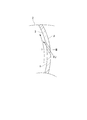
- FIG. 2 is a view showing a cross section taken along line AA of FIG.
- the line AA is a line passing through an intermediate position in the height direction of the blade 3 with respect to the disk surface 4.
- the tip end t of the blade 3 is formed to be curved from the radially inner side to the radially outer side of the disk 2. More specifically, like the disk surface 4 described above, it is formed in a concave shape along the axis O toward the radially inner side and gradually along the radial direction toward the radially outer side.
- the blade 3 is formed such that its height dimension is higher on the inner side in the radial direction of the disk 2 and lower on the outer side in the radial direction with respect to the disk surface 4.
- a hole H penetrating the blade 3 from the pressure surface p toward the negative pressure surface n is formed.
- the hole H is formed so as to penetrate the blade 3 at a predetermined angle with respect to the thickness direction.
- the hole H is formed so that the positions of the inlet H1 on the pressure surface p side and the injection port H2 on the negative pressure surface n side are shifted from each other when viewed from the circumferential direction of the disk 2 and the inlet H1.
- the injection port H2 is formed to communicate with each other linearly. That is, the two impeller flow paths 10 and 10 adjacent to each other via the blade 3 are communicated with each other by the hole H.
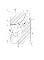
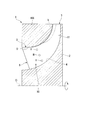
- the position where the hole H (inlet H1) is provided when the blade 3 is viewed from the pressure surface p side will be described with reference to FIG. That is, the position where the hole H is provided is inside the region A in FIG.
- the area A is an area surrounded by a virtual curve L1 along the fluid flow direction on the surface of the blade 3, virtual curves L2 and L3 orthogonal to the virtual curve L1, and the disk surface 4, respectively.
- the virtual curve L1 is set so as to curve along the fluid flow direction as described above and to pass through a position of about 60% of the height dimension from the disk surface 4 to the tip end t of the blade 3. Further, the virtual curve L2 is set so as to pass through a position of about 20% of the dimension of the blade 3 from the edge on the inlet 6 side to the edge on the outlet 7 side of the impeller flow path 10. Similarly, the virtual curve L3 is set so as to pass through a position of about 60% of the dimension from the edge on the inlet 6 side to the edge on the outlet 7 side. That is, the area A is a substantially rectangular area formed by a pair of long sides formed in an arc shape and a pair of short sides connecting the long sides.
- the impeller channel 10 has a flow direction that gradually changes from the axial direction to the radial direction from the radially inner side to the radially outer side of the disk 2, and is curved from the inlet 6 to the outlet 7 described above. Is done. Since the impeller flow path 10 is curved in this way and a centrifugal force is generated toward the radially outer side as the impeller 1 rotates, the impeller flow path 10 includes the main flow F in FIG. A secondary flow F2 indicated by a broken line arrow is formed.
- the hole H penetrates the blade 3 in the same direction as the extending direction of the line connecting the intermediate positions in the height direction of the blade 3 with respect to the disk surface 4. That is, it is substantially the same as the direction of the main flow F flowing in the vicinity of the hole H. Therefore, the flow direction of the jet flow FJ injected from the hole H is also substantially the same as the direction of the main flow F.
- the jet flow FJ having a directional component substantially the same as the main flow F collides with the secondary flow F2 having a directional component different from the flowing direction of the main flow F.
- the jet flow FJ passing through the hole H has a higher pressure than the surroundings.
- the jet flow FJ has a larger flow velocity than the secondary flow F2. Therefore, the secondary flow F2 is deflected by the jet flow FJ and becomes a flow in substantially the same direction as the jet flow FJ, that is, in the substantially same direction as the main flow F, and the direction component toward the region k is reduced.
- FIG. 5 is a view showing the blade 3 of the impeller 1 according to the present embodiment.
- the opening area of the injection port H2 provided on the negative pressure surface n side is larger than the opening area of the inlet port H1 provided on the pressure surface p side. Is formed. That is, the hole H is formed so that the opening area increases from the pressure surface p side toward the negative pressure surface n side.
- the pressure of the jet flow FJ passing through the hole H can be adjusted to be lower than that when the hole H is formed in a straight tube shape. That is, the flow velocity of the jet flow FJ can be reduced. Therefore, the secondary flow F2 can be reduced more effectively.
- the opening area of the injection port H2 provided on the negative pressure surface n side with respect to the opening area of the inlet port H1 provided on the pressure surface p side. May be formed small. That is, the hole H may be formed so that the hole area decreases from the pressure surface p side toward the negative pressure surface n side. According to this configuration, the pressure of the jet flow FJ passing through the hole H can be adjusted to be increased as compared with the case where the hole H is formed in a straight tube shape. That is, the flow velocity of the jet flow FJ can be increased. Therefore, the secondary flow F2 can be reduced more effectively.
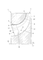
- a plurality of holes H are provided away from each other from the radially inner side to the radially outer side of the disk 2.
- three holes H are shown. These three hole portions H are arranged in a substantially straight line so as to be separated from the disk surface 4 as the hole portion H is located on the radially outer side from the hole portion H located on the radially inner side. These three holes H are all formed inside the region A shown in FIG.
- the three holes H may be arranged along the height direction of the blade 3 with respect to the disk surface 4. Also with this configuration, the jet flow FJ can be injected over a wider range, and the secondary flow F2 can be reduced more effectively.
- the hole H has a spiral groove C on the inner peripheral surface thereof.
- the groove C is formed so as to draw a circle along the inner peripheral surface of the hole H from the pressure surface p side toward the negative pressure surface n side. That is, the groove C has a female thread shape.
- the circumferential direction of the groove C may be clockwise or counterclockwise. According to this configuration, a swirl component according to the circumferential direction of the groove C can be imparted to the jet flow FJ passing through the hole H. Therefore, when the jet flow FJ collides with the secondary flow F2, the flow including the swirl component diffuses the secondary flow F2, so that the secondary flow F2 can be reduced more effectively.
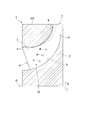
- the hole H includes one inflow port H1 provided on the pressure surface p side and a plurality of injection ports H2 provided on the negative pressure surface n side.
- FIG. 10 shows a configuration having three injection holes H2.
- the three injection ports H2 communicate with one inflow port H1.
- the three injection holes H2 are arranged so as to be separated from each other from the radially inner side to the radially outer side of the disk 2. That is, inside the hole H, three flow paths are formed from the inlet H1 to the respective injection ports H2. Furthermore, the flow path located radially inward among the flow paths communicates linearly with the inflow port H1.
- the jet flow FJ introduced from one inflow port H1 is branched into three flows toward three flow paths, and then injected from the three injection ports H2 to the negative pressure surface n side. Therefore, the jet flow FJ can be supplied to a wide range on the suction surface n side.
- the secondary flow F2 can be reduced more effectively, and the influence of the jet flow FJ on the main flow F can be suppressed.
- the opening shape of the hole H is circular, but the opening shape of the hole H is not limited to this, and is a polygonal shape such as a rectangular slit shape or a triangular shape. It may be. Further, it may be oval.
- the impeller according to the present invention it is possible to provide a highly efficient impeller that suppresses energy loss.
- the impeller according to the present invention can be applied to a rotary machine such as a centrifugal compressor.
Landscapes
- Engineering & Computer Science (AREA)
- Mechanical Engineering (AREA)
- General Engineering & Computer Science (AREA)
- Structures Of Non-Positive Displacement Pumps (AREA)
Priority Applications (3)
| Application Number | Priority Date | Filing Date | Title |
|---|---|---|---|
| CN201480062326.5A CN105723096A (zh) | 2014-01-22 | 2014-07-23 | 叶轮及离心压缩机 |
| EP14879801.0A EP3098454A4 (en) | 2014-01-22 | 2014-07-23 | Impeller and centrifugal compressor |
| US15/039,312 US20170167501A1 (en) | 2014-01-22 | 2014-07-23 | Impeller and centrifugal compressor |
Applications Claiming Priority (2)
| Application Number | Priority Date | Filing Date | Title |
|---|---|---|---|
| JP2014-009680 | 2014-01-22 | ||
| JP2014009680A JP6249219B2 (ja) | 2014-01-22 | 2014-01-22 | インペラ及び遠心圧縮機 |
Publications (1)
| Publication Number | Publication Date |
|---|---|
| WO2015111243A1 true WO2015111243A1 (ja) | 2015-07-30 |
Family
ID=53681066
Family Applications (1)
| Application Number | Title | Priority Date | Filing Date |
|---|---|---|---|
| PCT/JP2014/069451 Ceased WO2015111243A1 (ja) | 2014-01-22 | 2014-07-23 | インペラ及び遠心圧縮機 |
Country Status (5)
| Country | Link |
|---|---|
| US (1) | US20170167501A1 (enExample) |
| EP (1) | EP3098454A4 (enExample) |
| JP (1) | JP6249219B2 (enExample) |
| CN (1) | CN105723096A (enExample) |
| WO (1) | WO2015111243A1 (enExample) |
Families Citing this family (2)
| Publication number | Priority date | Publication date | Assignee | Title |
|---|---|---|---|---|
| US12180974B2 (en) | 2022-03-24 | 2024-12-31 | Copeland Lp | Variable inlet guide vane apparatus and compressor including same |
| US12516678B2 (en) | 2023-03-20 | 2026-01-06 | Copeland Lp | Variable inlet guide vane apparatus combined with compressor end cap |
Citations (4)
| Publication number | Priority date | Publication date | Assignee | Title |
|---|---|---|---|---|
| JPH10306796A (ja) * | 1996-05-17 | 1998-11-17 | Calsonic Corp | 遠心多翼ファン |
| JP2006194238A (ja) * | 2004-12-14 | 2006-07-27 | Toyota Industries Corp | 遠心圧縮機 |
| US20100329848A1 (en) | 2009-06-24 | 2010-12-30 | Rolls-Royce Plc | Shroudless blade |
| JP2012052439A (ja) * | 2010-08-31 | 2012-03-15 | Mitsubishi Heavy Ind Ltd | インペラ |
Family Cites Families (10)
| Publication number | Priority date | Publication date | Assignee | Title |
|---|---|---|---|---|
| GB256647A (en) * | 1925-08-08 | 1926-10-21 | Gen Electric | Improvements in or relating to centrifugal blowers and compressors |
| US2161182A (en) * | 1937-01-22 | 1939-06-06 | Alfred N Massey | Supercharger for internal combustion engines |
| DE860898C (de) * | 1944-02-29 | 1952-12-29 | Aeg | Laufrad fuer Kreiselpumpen |
| CH398320A (de) * | 1961-06-27 | 1966-03-15 | Sulzer Ag | Kreiselpumpe |
| JPS53123506U (enExample) * | 1977-03-07 | 1978-10-02 | ||
| DE4214753A1 (de) * | 1992-05-04 | 1993-11-11 | Asea Brown Boveri | Radialverdichter-Laufrad |
| EP0807760B1 (en) * | 1996-05-17 | 2003-09-17 | Calsonic Kansei Corporation | Centrifugal multiblade fan |
| US6860715B2 (en) * | 2003-04-24 | 2005-03-01 | Borgwarner Inc. | Centrifugal compressor wheel |
| US7261513B2 (en) * | 2004-12-01 | 2007-08-28 | Kabushiki Kaisha Toyota Jidoshokki | Centrifugal compressor |
| CN202326441U (zh) * | 2011-12-02 | 2012-07-11 | 杭州求是透平机制造有限公司 | 一种用于离心压缩机叶片扩压器的楔形叶片 |
-
2014
- 2014-01-22 JP JP2014009680A patent/JP6249219B2/ja not_active Expired - Fee Related
- 2014-07-23 CN CN201480062326.5A patent/CN105723096A/zh active Pending
- 2014-07-23 WO PCT/JP2014/069451 patent/WO2015111243A1/ja not_active Ceased
- 2014-07-23 US US15/039,312 patent/US20170167501A1/en not_active Abandoned
- 2014-07-23 EP EP14879801.0A patent/EP3098454A4/en not_active Withdrawn
Patent Citations (4)
| Publication number | Priority date | Publication date | Assignee | Title |
|---|---|---|---|---|
| JPH10306796A (ja) * | 1996-05-17 | 1998-11-17 | Calsonic Corp | 遠心多翼ファン |
| JP2006194238A (ja) * | 2004-12-14 | 2006-07-27 | Toyota Industries Corp | 遠心圧縮機 |
| US20100329848A1 (en) | 2009-06-24 | 2010-12-30 | Rolls-Royce Plc | Shroudless blade |
| JP2012052439A (ja) * | 2010-08-31 | 2012-03-15 | Mitsubishi Heavy Ind Ltd | インペラ |
Also Published As
| Publication number | Publication date |
|---|---|
| EP3098454A1 (en) | 2016-11-30 |
| JP6249219B2 (ja) | 2017-12-20 |
| CN105723096A (zh) | 2016-06-29 |
| US20170167501A1 (en) | 2017-06-15 |
| EP3098454A4 (en) | 2017-08-16 |
| JP2015137592A (ja) | 2015-07-30 |
Similar Documents
| Publication | Publication Date | Title |
|---|---|---|
| WO2011007467A1 (ja) | インペラおよび回転機械 | |
| JP5709898B2 (ja) | 回転機械 | |
| EP3056741B1 (en) | Impeller of a compressor and compressor provided with same | |
| JP2009133267A (ja) | 圧縮機のインペラ | |
| JP2018115581A (ja) | タービン排気室 | |
| JP2017203427A (ja) | ターボチャージャ | |
| WO2018155458A1 (ja) | 遠心回転機械 | |
| JP6249219B2 (ja) | インペラ及び遠心圧縮機 | |
| JP2010025041A (ja) | 遠心流体機械 | |
| JP6874121B2 (ja) | 可変静翼、及び圧縮機 | |
| WO2014122819A1 (ja) | 遠心圧縮機 | |
| JP2018135836A (ja) | 遠心圧縮機 | |
| JP2017180155A (ja) | 遠心圧縮機 | |
| JP6800609B2 (ja) | 遠心圧縮機、ターボチャージャ | |
| JP2008190487A (ja) | 遠心型流体機械 | |
| JP2016180349A (ja) | 回転機械 | |
| JP6572195B2 (ja) | タービンユニット、ターボチャージャ | |
| JP2009108791A (ja) | タービンホイール | |
| JP2005240713A (ja) | 遠心圧縮機 | |
| JP6192008B2 (ja) | 回転機械 | |
| JP6279524B2 (ja) | 遠心圧縮機、ターボチャージャ | |
| JP2015031180A (ja) | 回転機械 | |
| US20190055947A1 (en) | Centrifugal rotary machine | |
| JP2019019765A (ja) | 遠心圧縮機、ターボチャージャ | |
| JP2005240680A (ja) | 遠心圧縮機 |
Legal Events
| Date | Code | Title | Description |
|---|---|---|---|
| 121 | Ep: the epo has been informed by wipo that ep was designated in this application |
Ref document number: 14879801 Country of ref document: EP Kind code of ref document: A1 |
|
| WWE | Wipo information: entry into national phase |
Ref document number: 15039312 Country of ref document: US |
|
| REEP | Request for entry into the european phase |
Ref document number: 2014879801 Country of ref document: EP |
|
| WWE | Wipo information: entry into national phase |
Ref document number: 2014879801 Country of ref document: EP |
|
| NENP | Non-entry into the national phase |
Ref country code: DE |