WO2015105152A1 - 商品払出装置 - Google Patents
商品払出装置 Download PDFInfo
- Publication number
- WO2015105152A1 WO2015105152A1 PCT/JP2015/050390 JP2015050390W WO2015105152A1 WO 2015105152 A1 WO2015105152 A1 WO 2015105152A1 JP 2015050390 W JP2015050390 W JP 2015050390W WO 2015105152 A1 WO2015105152 A1 WO 2015105152A1
- Authority
- WO
- WIPO (PCT)
- Prior art keywords
- product
- pedal
- commodity
- storage passage
- sold
- Prior art date
- Legal status (The legal status is an assumption and is not a legal conclusion. Google has not performed a legal analysis and makes no representation as to the accuracy of the status listed.)
- Ceased
Links
Images














Classifications
-
- G—PHYSICS
- G07—CHECKING-DEVICES
- G07F—COIN-FREED OR LIKE APPARATUS
- G07F11/00—Coin-freed apparatus for dispensing, or the like, discrete articles
- G07F11/02—Coin-freed apparatus for dispensing, or the like, discrete articles from non-movable magazines
- G07F11/04—Coin-freed apparatus for dispensing, or the like, discrete articles from non-movable magazines in which magazines the articles are stored one vertically above the other
- G07F11/16—Delivery means
- G07F11/24—Rotary or oscillatory members
-
- G—PHYSICS
- G07—CHECKING-DEVICES
- G07F—COIN-FREED OR LIKE APPARATUS
- G07F5/00—Coin-actuated mechanisms; Interlocks
- G07F5/20—Coin-actuated mechanisms; Interlocks specially adapted for registering coins as credit, e.g. mechanically actuated
- G07F5/22—Coin-actuated mechanisms; Interlocks specially adapted for registering coins as credit, e.g. mechanically actuated electrically actuated
-
- G—PHYSICS
- G07—CHECKING-DEVICES
- G07F—COIN-FREED OR LIKE APPARATUS
- G07F9/00—Details other than those peculiar to special kinds or types of apparatus
Definitions
- the present invention relates to a commodity dispensing apparatus, and more particularly, to a vending machine that sells commodities such as canned beverages and plastic bottled beverages, for example, commodity dispensing that appropriately unloads commodities stored in a commodity storage passage It relates to an apparatus.
- a commodity storage rack is provided in a commodity storage inside a main body cabinet which is a vending machine main body.
- the product storage rack has a product storage passage extending along the vertical direction, and a product unloading device disposed in the lower part of the product storage passage.
- the commodity carry-out device is configured to include a lower pedal and an upper pedal.
- the lower pedal and the upper pedal are linked to an AC solenoid, which is an actuator, via a link, and appropriately moved to and from the product storage passage when the AC solenoid is energized.
- the upper pedal in the standby state, the upper pedal is in a state of being retreated from the product storage passage, while the lower pedal is in a state of advancing and moving to the product storage passage.
- the lower pedal contacts the lowermost product stored in the product storage passage, and the downward movement of the product stored in the product storage passage is restricted.
- the upper pedal is advanced to the product storage passage via the link when the AC solenoid is energized.
- the AC solenoid By moving and contacting the second lowest item, the item and items stored above the item are restricted from moving downward.
- the lower pedal retracts from the product storage passage, the lowermost product is carried out only downward, and when the product slips through the lower pedal, the lower pedal is attached with a spring. Move forward to the product storage passage by force.
- Patent No. 2749917 gazette
- the product delivery device proposed in Patent Document 1 since the product delivery devices from which the AC solenoids have been removed are back-to-back with each other and the drive source and the cam are provided between them, the number of product delivery devices is increased. Although it is possible to reduce the number of driving sources, it has been difficult to separate the two product delivery devices bonded back to back, which are component elements, and use only one of them. That is, the product delivery apparatus proposed in Patent Document 1 can be applied to a product storage rack provided with an even number of product storage passages adjacent to each other in front and back, but for a product storage rack provided with an odd number of product storage passages It could not be used as an individual product delivery device.
- the product delivery device is provided with two types of product delivery devices having different widths corresponding to the types of product storage racks, that is, for products with relatively small maximum widths and products with relatively large maximum widths. It is general to mount a commodity unloading device having a width corresponding to the maximum width of the commodity stored in the rack on the commodity storage rack.
- the present invention can provide a product dispensing apparatus capable of reducing manufacturing costs and flexibly responding to the number of product storage passages adjacent to each other. To aim.
- the commodity delivery apparatus is applied to one commodity storage passage which stores the input commodity along the vertical direction, and is stored in the one commodity storage passage in the standby state. Restricts the downward movement of the stored goods, and when driven, carries out the lowermost goods stored in the one goods storage passage downward;
- the present invention is applied to the other product storage passage adjacent to one product storage passage and storing the input products along the vertical direction, and in the standby state, the products stored in the other product storage passage are directed downward. Control movement, while driving, it is possible to tie back with each other back-to-back with the other product carrying out device for carrying out the lowermost product stored in the other product storage passage downward.
- the one commodity delivery apparatus when one of the commodity delivery apparatuses is given a drive source for itself and the other commodity delivery apparatus and an ejection command, the one commodity delivery apparatus and the other commodity delivery apparatus according to the ejection command.
- Driving force application means for applying a driving force from the driving source
- a product delivery device which is alternatively selected by the driving force application means and provided with a driving force is determined in advance.
- Control means for performing a sell-out process in which the product in the product storage passage of the product carry-out device is sold out as being abnormal only in the product carry-out device when not driven within the specified time. I assume.
- control means is alternatively selected by the drive force application means and does not drive the commodity delivery apparatus to which the drive force is applied within a predetermined time. It is characterized in that a retry process is performed in which the operation for applying the driving force is performed again by selecting the product delivery device with respect to the driving force applying means.
- control means is alternatively selected by the drive force application means and does not drive the commodity delivery apparatus to which the drive force is applied within a predetermined time. It is characterized in that it is returned to a preset standby position and retry processing is performed.
- the driving force application means is disposed so as to be capable of rotating in the forward and reverse directions about its own central axis, and forward rotation is given when an unloading command is given to one commodity unloading device.
- the other product delivery device is given a delivery command, it is provided so as to be rotatable around its own axis corresponding to the output gear and the product delivery device, which are reversely rotated.
- the present invention is characterized in that, in the commodity delivery apparatus, the drive source is common to the one commodity delivery apparatus and the other commodity delivery apparatus.
- the present invention is characterized in that, in the above-mentioned commodity delivery apparatus, the drive source is a direct current motor.
- the apparatus and the other product delivery device are alternatively selected to provide the driving force application means for applying the driving force from the drive source, the number of drive sources is reduced relative to the number of product delivery devices. And the manufacturing cost can be reduced. Moreover, since one of the product delivery devices is provided with the drive source and the driving force application means, only one of the product delivery devices can be used.
- the present invention can be used not only for product storage devices provided with even-numbered product storage passages lined up in front and back, but also for product storage devices provided with odd-numbered product storage passages lined up in front and back. Therefore, while being able to attain reduction of manufacturing cost, it is effective in the ability to respond flexibly according to the number of goods storage passages adjacent to back and forth.
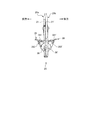
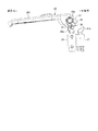
- FIG. 1 is a cross-sectional side view showing a case where an internal structure of a vending machine to which a commodity delivery apparatus according to an embodiment of the present invention is applied is viewed from the right side.
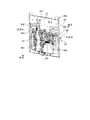
- FIG. 2 is a side view showing the commodity delivery apparatus shown in FIG. 1 as viewed from the right.
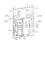
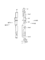
- FIG. 3 is a perspective view showing the commodity delivery apparatus shown in FIG. 1 as viewed from the right front side.
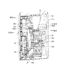
- FIG. 4 is a perspective view showing the commodity delivery apparatus shown in FIG. 1 as viewed from the rear right side.
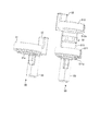
- FIG. 5 is a perspective view showing the first commodity unloading device shown in FIGS. 2 to 4 as viewed from the rear right side.
- FIG. 6 is an explanatory view schematically showing a case where the main part of the first product unloading device shown in FIGS. 2 to 5 is viewed from the right side.
- FIG. 7 is an explanatory view schematically showing a case where the main part of the first commodity unloading device shown in FIGS. 2 to 5 is viewed from the right side.
- FIG. 8 is an explanatory view schematically showing a case where the main part of the first commodity unloading device shown in FIGS. 2 to 5 is viewed from the right side.
- FIG. 9 is a perspective view showing a base of the first commodity carry-out apparatus shown in FIGS.
- FIG. 10 is a perspective view showing a bearing and a harness guide attached to the base shown in FIG. FIG.
- FIG. 11 is a perspective view showing a first sold-out link and a second sold-out link.
- FIG. 12 is a side view showing the main part of the commodity delivery apparatus in FIG. 2 to FIG.
- FIG. 13 is a side view showing the relationship between the first sold-out link and the first sold-out detection switch when the lower pedal is in the product existing standby state.
- FIG. 14 is a perspective view of a rotation stopper which constitutes the first product carry-out apparatus shown in FIGS.
- FIG. 15 is a perspective view showing the relationship between the first sold-out link and the first sold-out detection switch when the lower pedal moves backward.
- FIG. 16 is a perspective view showing the main part of the drive unit in the first product unloading device, and showing the case viewed from the front right side.
- FIG. 17 shows an essential part of the drive unit in the first product unloading device, and is an exploded perspective view showing the case viewed from the rear left side.
- FIG. 18 is a perspective view showing the second commodity unloading device shown in FIGS. 2 to 4 as viewed from the right front side.
- FIG. 19 is an explanatory view schematically showing a case where the main part of the second product unloading device shown in FIG. 2 to FIG. 4 and FIG. 18 is viewed from the right side.
- FIG. 20 is a perspective view showing a base of the second commodity carrying-out apparatus shown in FIG.
- FIG. 21 is a perspective view showing a bearing and a guide attached to the base shown in FIG.
- FIG. 22 is a block diagram showing a characteristic control system of the commodity delivery apparatus.
- FIG. 23 is a perspective view showing a case where the first product unloading device is viewed from the rear right side.
- FIG. 24 is a flowchart showing the contents of the payout control process performed by the payout control unit.
- FIG. 25 is a perspective view showing a case where the first product unloading device is viewed from the rear right side.
- FIG. 26 is an explanatory view showing the operation of the main part of the drive unit as viewed from the front.
- FIG. 27 is an explanatory view showing the operation of the main part of the drive unit as viewed from the rear and the front.
- FIG. 28 is a flowchart showing the contents of the retrial process (1) in the payout control process shown in FIG. FIG.
- FIG. 29 is a flowchart showing the contents of the retrial process (2) in the payout control process shown in FIG.
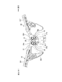
- FIG. 30 is an exploded perspective view showing a modification of the drive unit.
- FIG. 31 is a perspective view showing a modified example of the commodity delivery apparatus.
- FIG. 1 is a cross-sectional side view showing a case where an internal structure of a vending machine to which a commodity delivery apparatus according to an embodiment of the present invention is applied is viewed from the right side.
- the vending machine illustrated here is for selling a product in a cooled or heated state, and is configured to include a main body cabinet 1, an outer door 2 and an inner door 3.
- the main body cabinet 1 is configured in a rectangular shape whose front surface is opened by combining a plurality of steel plates as appropriate, and has a commodity storage case 4 of a heat insulation structure inside thereof.
- the outer door 2 is for covering the front opening of the main body cabinet 1 and is disposed at one edge of the main body cabinet 1 so as to be openable and closable. Display window, commodity selection button, bill insertion slot, coin insertion slot, return lever, integrated indicator, coin return slot, commodity outlet 2a, etc. are required on the front of this outer door 2 when selling commodities etc. Things are provided.
- the inner door 3 is a heat insulating door divided into upper and lower halves for covering the front opening of the commodity storage case 4, and the upper heat insulating door 3 a is one side edge of the outer door 2 at a position inside the outer door 2.
- the lower heat insulating door 3 b is disposed at one side edge of the main body cabinet 1 so as to be openable and closable.
- a commodity outlet 3 c for carrying the commodity out of the commodity storage 4 is provided below the lower heat insulation door 3 b in the inner door 3.
- a commodity shooter 5 is provided inside the commodity storage 4, and a temperature control unit is provided in a region (hereinafter also referred to as "heat exchange region") below the commodity shooter 5.
- the product storage rack 10 is disposed in an area (hereinafter, also referred to as a "product storage area”) above the product shooter 5 while the 6 is disposed.
- the commodity shooter 5 is a plate-like member for guiding the commodity carried out of the commodity storage rack 10 to the commodity outlet 3c of the inner door 3, and is disposed in a manner to gradually incline downward toward the front side There is. Although not clearly shown in the figure, the commodity shooter 5 is provided with a large number of vent holes (not shown) for communicating between the heat exchange area and the commodity storage area.
- the temperature control unit 6 is for maintaining the internal atmosphere of the product storage case 4 at a desired temperature state, and includes an evaporator 6a of a refrigeration cycle, an electric heater 6b, and a blower fan 6c.
- this temperature control unit 6 for example, when the blower fan 6c is driven in a state where the refrigeration cycle is operated, the air cooled in the evaporator 6a is fed upward through the vent holes of the product shooter 5, so the product storage area Can be maintained at a low temperature.
- the blower fan 6c is driven in a state in which the electric heater 6b is energized, the air heated by the electric heater 6b is supplied upward through the vent holes of the product shooter 5, so the product storage area is maintained at high temperature. be able to.
- the compressor, the condenser and the expansion valve of the refrigeration cycle are disposed in the machine room 7 which is not shown in the figure but is outside the commodity storage case 4.
- the product storage racks 10 are arranged in three rows in the front and rear direction, and are configured in a serpentine shape along the vertical direction by arranging the passage components 12 between the pair of base side plates 11.
- a plurality of (two in the illustrated example) product storage channels 13 are provided, and a plurality of products are stored inside the product storage channels 13 in an upside-down posture along the vertical direction.
- the passage components 12 are appropriately disposed to face each other on the front side and the rear side of the commodity storage passage 13 and are fixed to the base side plate 11.
- two commodity storage passages 13 are provided adjacent to each other in the front and back direction.
- the front product storage passage 13 is also referred to as a first product storage passage 13a
- the rear product storage passage 13 is also referred to as a second product storage passage 13b.
- the passage component 12 is provided with a flapper which is not explicitly shown in the figure.
- the flapper is pivotally disposed in the passage component 12 in such a manner as to move forward and backward with respect to the commodity storage passage 13.
- the flapper is urged by a coil spring (not shown) to move forward into the product storage passage 13 in a normal state. Then, by coming into contact with the product passing through the product storage passage 13, the self moves backward along the meandering product storage passage 13 against the biasing force of the coil spring to correct the posture of the product. .
- the top tray 14 is provided in the upper part of the product storage passage 13 and the product delivery device 20 is provided in the lower part of the product storage passage 13.
- the top tray 14 is configured by bending a flat sheet metal, and is disposed between the base side plates 11 in a manner of being inclined gradually downward from the front to the rear.
- the upper surface of the top tray 14 as described above constitutes a commodity guiding passage 15 for guiding the commodity introduced through the inlet to the commodity storage passage 13.
- FIG. 2 to 4 respectively show the commodity delivery apparatus 20 shown in FIG. 1, and FIG. 2 is a side view showing the case viewed from the right side, and FIG. 3 is a perspective view showing the case viewed from the right front side FIG. 4 is a perspective view showing the case viewed from the rear right side.
- the commodity delivery apparatus 20 includes one commodity unloading device (hereinafter also referred to as a first commodity unloading device) 20a and the other commodity unloading device (hereinafter also referred to as a second commodity unloading device). And the second commodity delivery device 20b are held back to back and held together.
- FIGS. 2 to 4 show a state in which no commodity is stored in any of the first commodity unloading device 20a and the second commodity unloading device 20b which constitute the commodity delivery device 20.
- FIG. 5 is a perspective view showing the first product delivery device 20a shown in FIGS. 2 to 4 as viewed from the rear right side.
- the configuration of the first product unloading device 20a will be described, and then the second product unloading device 20b will be described.
- FIGS. 6 to 8 are explanatory views schematically showing the main part of the first commodity carry-out device 20a shown in FIGS. 2 to 5 as viewed from the right.
- the configuration of the first commodity carry-out device 20a will be described using FIG. 6 to FIG. 8 as appropriate.
- the first commodity carry-out device 20a is applied to the first commodity storage passage 13a, and is disposed below the first commodity storage passage 13a.
- the first product carry-out device 20a controls the behavior of the product between the opposing passage width defining plate 16 to store the product in the first product storage passage 13a in the standby state while driving.
- the function functions to carry out the corresponding products one by one to the product shooter 5, and includes a base 21.
- the base 21 is formed by cutting and bending a steel plate, and is disposed in such a manner that the surface of the base 21 faces the passage width determining plate 16.
- the side wall 21a is formed by bending both side portions of the base 21, and a first insertion hole 22 and a second insertion hole 23 are formed in the middle portion. The peripheral edges of the first insertion hole 22 and the second insertion hole 23 are bent in the same manner as the side wall 21 a to form a flange.
- the first insertion holes 22 and the second insertion holes 23 are formed side by side, and have the same size in the upper and lower dimensions.
- the first insertion hole 22 is located on the left side of the second insertion hole 23, and the left and right width of the first insertion hole 22 is the left and right of the second insertion hole 23. It is larger than the width.
- the first insertion holes 22 and the second insertion holes 23 are through openings (recesses for causing the lower pedal 28 and the upper pedal 29 described later to retract into the base 21 described later), which form a substantially rectangular shape as a whole.
- An upper end portion of the first insertion hole 22 protrudes leftward, and an upper end portion of the second insertion hole 23 protrudes rightward.
- a first left bearing piece 22 a is provided at the left side edge of the first insertion hole 22, and a first right bearing piece 22 b is provided at the right edge of the first insertion hole 22.
- a second left bearing piece 23a is provided at the left side edge of the second through hole 23, and a second right bearing piece 23b is provided at the right side edge of the second insertion hole 23.
- the first left bearing piece 22a and the second right bearing piece 23b correspond to flanges formed on the periphery of the first insertion hole 22 and the second insertion hole 23, respectively.
- the first right bearing piece 22b and the second left bearing piece 23a are integrally formed on the base 21 where the bearing portion 24 described later is fitted and held, and are formed in a U-shaped (discontinuous) cross section.
- the bearing holding portion has a function of maintaining the strength of the base 21 even when a large through opening formed of the first insertion hole 22 and the second insertion hole 23 having a substantially rectangular shape as a whole is formed in the base 21.
- a bearing 24 and a harness guide 25 as shown in FIG. 10 are attached to the base 21 having such a configuration.
- the bearing portion 24 is made of a resin material or the like, and is fitted between the first right bearing piece 22b and the second left bearing piece 23a.
- the harness guide 25 is made of a resin material or the like in the same manner as the bearing portion 24, and is fitted along the right side wall 21a of the base 21 in a manner adjacent to the second right bearing piece 23b.
- the harness guide 25 is for winding the harness of the electric component mounted on the first product unloading device 20a. Further, the harness guide 25 has a role as a guide member when the first product delivery device 20a and the second product delivery device 20b are held together back to back.
- the harness guide 25 is provided with a first sold-out detection switch 26 and a second sold-out detection switch 27.
- the first sold-out detection switch 26 is disposed in line with the second sold-out detection switch 27 in front of and behind the second sold-out detection switch 27.
- the first sold-out detection switch 26 is a so-called push-type switch, and includes a contact 26a biased to stand by a spring (not shown). When the contact 26a is not pressed, the first sold-out detection switch 26 is turned off and sends an off signal to the payout control unit 110 described later, while the contact 26a is pressed and the biasing force of the spring is applied. In the case of displacement in opposition, it is turned on to send an on signal to the payout control unit 110.
- the first sold-out detection switch 26 is turned off when the contact 26a is not pressed, but is turned on when the contact 26a is pressed and displaced. In the present invention, the first sold-out detection switch 26 may be turned on when the contact 26a is not pressed, but may be turned off when the contact 26a is pressed and displaced. .
- the second sold-out detection switch 27 is located rearward of the first sold-out detection switch 26.
- the second sold-out detection switch 27 is a so-called push-type switch, and includes a contact 27a biased to stand up by a spring (not shown).
- the second sellout detection switch 27 is turned off and sends an off signal to the payout control unit 110 described later, while the contact 27a is pressed and the biasing force of the spring is applied. In the case of displacement in opposition, it is turned on to send an on signal to the payout control unit 110.
- the second sold-out detection switch 27 is turned off when the contact 27a is not pressed, but is turned on when the contact 27a is pressed and displaced. In the present invention, the second sold-out detection switch 27 may be turned on when the contact 27a is not pressed, but may be turned off when the contact 27a is pressed and displaced. .
- the base 21 is provided with a first swing support shaft 28a and a second swing support shaft 29a.
- the first swing support shaft 28a extends in a substantially horizontal direction, and the first left bearing piece 22a, the first right bearing piece 22b, the second left bearing piece 23a, the second right bearing piece 23b, and the bearing portion It is a shaft-like member which is constructed to penetrate through the through holes 22a1, 22b1, 23a1, 23b1 and 24a formed in the lower part 24, and the lower pedal 28 is supported at the middle part thereof.
- a first sold-out link 30 is disposed at the right end of the first swing support shaft 28a.
- the first sold-out link 30 is configured to include a first sold-out base 31, a first sold-out abutting portion 32, and a first sold-out pressing portion 33.
- the first sold-out base portion 31 has a substantially disk shape, and is formed with a through hole 31a which allows the right end portion of the first swing support shaft 28a to pass therethrough.
- the first sold-out contact portion 32 extends leftward from the rear side portion of the first sold-out base 31.
- the first sold-out pressing portion 33 is formed to project rightward from the lower side portion of the first sold-out base 31.
- the through hole 31a formed in the first sold-out base portion 31 is formed larger than the first swing support shaft 28a, and the first sold-out link 30 can freely move relative to the first swing support shaft 28a. Is configured as.
- the second swing support shaft 29a extends in a substantially horizontal direction in a region above the first swing support shaft 28a, such that the first left bearing piece 22a, the first right bearing piece 22b, and the second left side It is a shaft-like member constructed to penetrate through the through holes 22a2, 22b2, 23a2, 23b2, and 24b formed in the bearing piece 23a, the second right bearing piece 23b, and the bearing portion 24. Supports.
- the lower pedal 28 is a plate-like member, and is disposed in such a manner as to be able to swing around the central axis of the first swing support shaft 28 a by inserting the first swing support shaft 28 a at the base end portion. ing.
- the tip end portion of the lower pedal 28 extends outward in the radial direction of the first swing support shaft 28 a, and the first insertion hole 22 when swinging around the central axis of the first swing support shaft 28 a. It is possible to move forward and backward to the first product storage passage 13 a through the second insertion hole 23. That is, the lower pedal 28 is disposed swingably in such a manner as to move forward and backward with respect to the first product storage passage 13a.
- a lower pedal spring 28 b is interposed between the lower pedal 28 and the base 21.
- the lower pedal spring 28b always urges the lower pedal 28 in the advancing movement direction with respect to the first product storage passage 13a. More specifically, as shown in FIG. 6, the lower pedal spring 28b is in a standby position for waiting the lower pedal 28 such that the tip of the lower pedal 28 is positioned above the first swing support shaft 28a Also called attitude).
- the lower pedal spring 28b is at the same height level as the first swing support shaft 28a, as shown in FIG.
- the lower pedal 28 is placed in a standby position (hereinafter, also referred to as a product-present standby position) to be positioned.
- the base end of the lower pedal 28 abuts on the first sold-out contact portion 32 of the first sold-out link 30.
- the first sold-out link 30 rotates with the first swing support shaft 28 a as an axis, whereby the first sold-out pressing unit 33 presses the contact 26 a of the first sold-out detection switch 26.
- the contact 26a is pressed and displaced forward against the biasing force of the spring to be turned on and send an on signal to the payout control unit 110. It becomes.
- the lower pedal 28 when the lower pedal 28 is in the product-ready standby position, as shown in FIG. 13, the base end of the lower pedal 28 is separated from the first sold-out contact portion 32 of the first sold-out link 30.
- the first sold-out link 30 is in a free state.
- the contact 26a is turned up by being biased by the spring and thus becomes an off state, and an off signal is sent to the payout control unit 110. . That is, the first sold-out link 30 in the free state is rotated about the first swing support shaft 28 a as the first sold-out pressing portion 33 is pressed by the contact 26 a.
- the lower pedal 28 includes a plate-like pedal main body 281 and a pair of guide portions 282.
- the pair of guide portions 282 is provided on the back side of the pedal body 281.
- the respective guide portions 282 are plate-like members extending along the vertical direction, and are formed to face each other.
- Guide grooves 283 are formed on opposing surfaces of the guide portions 282 facing each other.
- the guide groove 283 is located at the lowermost position in the state (shown in FIG. 6) in which the lower pedal 28 is disposed at the advanced position where the lower pedal 28 has advanced most to the first product storage passage 13a.
- the state (shown in FIG. 8) in which the lower pedal 28 is disposed at the most retracted position with respect to the first product storage passage 13a (the state shown in FIG. 8)
- the first guide 283 b and the second guide 283 c are connected such that the contact portion 283 d located on the rotary stopper 36 and in contact with the pedal operation shaft 361 of the rotation stopper 36 and the insertion portion 283 a and the contact portion 283 d are continuous. And have.
- the first guiding portion 283b is disposed obliquely upward so as to be separated from the fitting portion 283a with respect to the base 21 in a state where the lower pedal 28 is disposed at the most advanced position (advanced position) with respect to the first product storage passage 13a.
- the guide portion 282 is formed in such a manner as to incline obliquely upward to approach the base 21 and reach the contact portion 283d.
- the second guiding portion 283c is inclined so as to be separated from the contact portion 283d with respect to the base 21 in a state where the lower pedal 28 is disposed at the most advanced position (advanced position) relative to the first product storage passage 13a. It is formed in the guide part 282 in the aspect which inclines below and reaches the insertion part 283a.
- the radially outward length of the lower pedal 28 from the first swing support shaft 28a is the passage width when it is positioned at the most advanced position (advanced position) with respect to the first product storage passage 13a. It is set to a length capable of securing a gap smaller than the maximum width of the narrowest product with the regulation plate 16.
- the upper pedal 29 is a plate-like member, and the base 21 can be rocked about the central axis of the second rocking support shaft 29a by inserting the second rocking support shaft 29a at the base end. It is arranged.
- the tip end portion of the upper pedal 29 extends outward in the radial direction of the second swing support shaft 29a, and the first insertion hole 22 when swinging around the central axis of the second swing support shaft 29a. It is possible to move forward and backward to the first product storage passage 13 a through the second insertion hole 23. That is, the upper pedal 29 is disposed swingably in such a manner as to move forward and backward with respect to the first product storage passage 13a.
- An upper pedal spring (not shown) is interposed between the upper pedal 29 and the base 21.
- the upper pedal spring always biases the upper pedal 29 in the backward movement direction with respect to the first product storage passage 13a.
- the upper pedal 29 is provided with a pressing inclined surface 291, a recess 292, a stopper contact portion 293 and a protrusion 294.
- the pressing inclined surface 291 is provided at the tip of the upper pedal 29, and when the upper pedal 29 is moved backward with respect to the first product storage passage 13a, the pressure inclined surface 291 is gradually lowered toward the first product storage passage 13a.
- a curved inclined surface formed in the following manner.
- the recess 292 is provided on the back side of the upper pedal 29 and is a single recess extending along a substantially horizontal direction formed in a manner of opening on both side surfaces of the upper pedal 29.
- the stopper abutting portion 293 is a portion on which a stopper pin 34 a described later abuts, and is provided in such a manner as to be inclined above the concave portion 292 on the back surface of the upper pedal 29.
- the projecting portion 294 is provided in a mode in which it protrudes toward the first product storage passage 13 a at the base end portion of the upper pedal 29.
- the upper pedal 29 is biased to move backward to the first product storage passage 13a by the biasing force of the upper pedal spring, but the stopper pin 34a abuts on the recess 292 to move to the first product storage passage 13a.
- the initial position is set to the state of backward movement.
- Such an upper pedal 29 passes the second rocking support shaft 29a in a state (state shown in FIG. 8) positioned at a position (advanced position) which has advanced most to the first product storage passage 13a. It is in an inclined state forward to the surface.
- the length of the radially outward direction from the second swing support shaft 29a of the upper pedal 29 is smaller than the maximum width of the product having a smaller maximum width with the passage width defining plate 16 in the above-described forward inclined state. It is set to the length which can secure a gap.
- a stopper pin 34a, a pedal stopper pin 34b and a stopper shaft 34c are provided between the bearing portion 24 and the second right bearing piece 23b.
- the stopper pin 34a is a shaft-like member disposed along the substantially horizontal direction between the bearing portion 24 and the second right bearing piece 23b, and one end thereof is the stopper pin insertion hole 23b3 of the second right bearing piece 23b. And the other end is inserted through the stopper pin insertion hole 24c1 of the bearing portion 24 exposed from the second left bearing piece 23a.
- the stopper pin 34a is coupled to the pedal link 35, and can move in the vertical direction inside the stopper pin insertion holes 23b3 and 24c1 as the pedal link 35 moves in the vertical direction.
- the stopper pin 34a is in contact with the recess 292 of the upper pedal 29 at the initial position.
- the pedal stopper pin 34b is a shaft-like member disposed along the substantially horizontal direction between the bearing portion 24 and the second right bearing piece 23b, and one end portion thereof is a pedal stopper pin support groove 24c2 of the bearing portion 24 (see FIG. Similar to the stopper pin insertion hole 24c1, it is a long groove extending up and down, is closed by a groove bottom which is a drawing-out portion of the reference numeral 24c1, and is inserted into the second right side.
- the pedal stopper pin support groove 23b4 of the bearing piece 23b is inserted.
- An insertion groove 23a4 is provided in the second right bearing piece 23b so that the pedal stopper pin insertion hole 24c2 is exposed.
- the pedal stopper pin 34b is coupled to the pedal link 35, and can be moved along the vertical direction inside the pedal stopper pin support grooves 23b4 and 24c2 as the pedal link 35 moves in the vertical direction. is there. When the pedal link 35 is moved in the vertical direction, the circumferential surface of the pedal stopper pin 34b slides in the grooves of the pedal stopper pin support grooves 23b4 and 24c2.
- the stopper shaft 34c is a shaft-like member disposed along the substantially horizontal direction between the bearing portion 24 and the second right bearing piece 23b, and one end thereof is inserted into the stopper shaft insertion hole 24c3 of the bearing portion 24. The other end portion is inserted through the through hole 23b5 of the second right bearing piece 23b.
- the second right bearing piece 23b is formed with an insertion hole for the stopper shaft 34c.
- the stopper shaft 34c supports a rotation stopper 36 at an intermediate portion thereof.
- the rotation stopper 36 allows the stopper shaft 34c to be inserted into the insertion hole of the base end portion and can swing around the central axis of the stopper shaft 34c.
- the tip end portion of the rotation stopper 36 extends outward in the radial direction of the stopper shaft 34c, and when pivoted around the central axis of the stopper shaft 34c, the first product storage passage 13a through the second insertion hole 23 It is possible to move forward and backward.
- the pivoting stopper 36 has the pedal operating shaft 361 as the pedal operating shaft 361 passes through the through hole 36 a at the tip end.
- the pedal operation shaft 361 is a shaft-like member disposed substantially in the horizontal direction, and both ends thereof are fitted in the guide groove 283 of the lower pedal 28.
- a pedal operating spring (not shown) is interposed between the rotation stopper 36 and the base 21.
- the pedal operation spring always biases the rotation stopper 36 in the advancing direction with respect to the first product storage passage 13a.
- Such a rotation stopper 36 is biased by the pedal operation spring in the direction of advancing and moving relative to the first product storage passage 13a, and the pedal stopper pin 34b enters the recess 36b of the rotation stopper 36.
- the movement in the backward movement direction is restricted by coming into contact with the pedal stopper pin 34b, and the initial position in the state of advancing and moving with respect to the first product storage passage 13a is set.
- both ends of the pedal operation shaft 361 of the rotation stopper 36 are positioned at the fitting portion 283a of the guide groove 283, and the lower pedal 28 is the first product.
- An initial position is set at a position moved forward to the storage passage 13a.
- such a rotation stopper 36 is provided with a flat blind portion 36c extending upward on the back side, that is, the back side of the recess 36b. .
- the blind portion 36c covers a portion of the pedal stopper pin 34b opposite to the first product storage passage 13a. More specifically, the blind portion 36c covers a portion of the pedal stopper pin 34b moving in the vertical direction, which is opposite to the first product storage passage 13a.
- the pedal link 35 is a long plate-like member extending along the vertical direction, and extends upward after the upper portion is bent forward. At the upper portion of the pedal link 35, a contact piece 351 extending rearward and then extending obliquely upward is provided, and a locking portion 352 for locking the link spring 35a is provided. .
- the link spring 35 a is interposed between the pedal link 35 and the base 21 and always biases the pedal link 35 downward.
- the stopper pin 34a is disposed at the lower end of the stopper pin insertion holes 23b3 and 24c1, and the lower end of the pedal stopper support groove 23b4 and 24c2
- the pedal stopper pin 34b is disposed on the In this state, the recess 292 of the upper pedal 29 disposed at the retracted position abuts against the stopper pin 34a.
- the rotation stopper 36 disposed at the advanced position is in contact with the pedal stopper pin 34b, and the backward movement of the rotation stopper 36 is restricted.
- the pedal operation shaft 361 of the rotation stopper 36 disposed at the advanced position is inserted into the insertion portion 283a of the lower pedal 28, whereby the backward movement of the lower pedal 28 disposed at the advanced position is restricted. There is.
- the stopper pin 34a is disposed at the upper end of the stopper pin insertion holes 23b3 and 24c1.
- the pedal stopper pin 34b is disposed at the upper end portion of the pedal stopper pin support grooves 23b4 and 24c2.
- the base end of the lower pedal 28 is separated from the first sold-out contact portion 32 of the first sold-out link 30, as shown in FIG.
- the sold-out link 30 is in a free state.
- the contact 26a is biased by the spring to be in an upright position, thereby maintaining the off state. That is, even when the lower pedal 28 moves backward, the first sold-out link 30 does not press the contact 26 a of the first sold-out detection switch 26 as in the product presence standby posture.
- the first commodity carry-out device 20a having such a configuration includes a drive unit 40 in addition to the above configuration.
- FIG. 16 and 17 show the main part of the drive unit 40 in the first product unloading device 20a, respectively, and FIG. 16 is an exploded perspective view showing the case seen from the front on the right side, and FIG. It is an exploded perspective view showing the case of
- the drive unit 40 is disposed in the central region of the upper portion on the back side of the base 21.
- the drive unit 40 includes a unit base 41 attached to the back of the base 21.
- the unit base 41 is formed of, for example, a resin material or the like, and is formed in a box shape whose rear surface is open.
- the unit cover 41 is closed by the attachment of a unit cover 42 made of resin to form an accommodation space between the unit base 41 and the unit cover 42.
- the motor 43, the gear member 44, the carrier switch 45, and the link lever 46 are housed in the housing space formed by the unit base 41 and the unit cover 42 in this manner.
- the motor 43 is a drive source, and is a direct-current motor capable of rotating in the forward and reverse directions in accordance with a command given from the payout control unit 110 described later.
- the motor 43 is disposed in a state of being held by the motor holding portion 41 a of the unit base 41.
- the gear member 44 is configured to include a worm gear 441, an intermediate gear 442 and an output gear 443.
- the worm gear 441 has a worm 441a and a worm wheel 441b.
- the worm 441 a has a cylindrical form and is attached to the output shaft 43 a of the motor 43.
- the worm wheel 441 b includes a disc-shaped first worm wheel 441 b 1 and a disc-shaped second worm wheel 441 b 2.
- the first worm wheel 441b1 is formed with a shaft-like portion that protrudes rearward at the central portion, and a gear portion formed of a plurality of teeth is formed on the circumferential surface.
- the second worm wheel 441b2 is located on the front side of the first worm wheel 441b1, and an axial portion whose central axis coincides with the central axis of the axial portion of the first worm wheel 441b1 protrudes forward.
- a gear portion formed of a plurality of teeth is also formed on the circumferential surface of the second worm wheel 441b2.
- Such a worm wheel 441b is inserted into the unit base 41 and the recesses 41b and 42b of the unit cover 42 while the gear portion of the first worm wheel 441b1 is engaged with the worm 441a. It is disposed rotatably around the central axis.
- the intermediate gear 442 includes a disk-shaped first intermediate gear 442 a and a disk-shaped second intermediate gear 442 b.
- the first intermediate gear 442a is formed with a shaft-like portion projecting rearward at the central portion and a gear portion formed of a plurality of teeth on the circumferential surface.
- the second intermediate gear 442b is located on the rear surface side of the first intermediate gear 442a, and an axial portion whose central axis coincides with the central axis of the axial portion of the first intermediate gear 442a protrudes forward. Are formed in the following manner. A gear portion formed of a plurality of teeth is also formed on the circumferential surface of the second intermediate gear 442b.
- the shaft-like portion is inserted into the concave portions 41 c and 42 c of the unit base 41 and the unit cover 42 in a state where the gear portion of the first intermediate gear 442 a meshes with the gear portion of the second worm wheel 441 b 2 Are arranged rotatably around the central axis of the shaft-like portion.
- the output gear 443 has a disk shape having a diameter larger than that of the worm wheel 441 b and the intermediate gear 442.
- a gear portion composed of a plurality of teeth is also formed on the circumferential surface of the output gear 443. Further, at the central portion of the output gear 443 is formed an axial portion projecting in the front-rear direction. Further, the output gear 443 has a cam portion 443a formed on the front surface and a pressing piece 443b formed on the rear surface.
- the cam portion 443a has an arc shape and is formed in a manner of projecting forward.
- the cam portion 443a is formed so that its arc-like length is large enough to hold the state after the pedal link 35 is moved upward.
- the pressing piece 443b has a substantially V-like shape, and is formed in such a manner as to project rearward on the rear surface which is the surface opposite to the cam portion 443a.
- the output gear 443 has a shaft-like portion by inserting the shaft-like portion into the unit base 41 and the recesses 41 d and 42 d of the unit cover 42 while the gear portion is in mesh with the gear portion of the second intermediate gear 442 b. It is disposed rotatably around the central axis.
- the carrier switch 45 is a so-called push switch, and includes a contact 45a.
- the carrier switch 45 is disposed on the unit base 41 so as to be held slightly above the area where the output gear 443 is disposed.
- the carrier switch 45 is turned on when the contact 45a is pressed, and is supplied to the payout control unit 110 as an on signal to that effect, and is turned off when the contact 45a is not pressed. The fact is given to the payout control unit 110 as an off signal.
- the link lever 46 includes a first link lever 461 and a second link lever 462.
- the first link lever 461 is formed of, for example, a resin material, and a through hole 461a1 is formed in the base end 461a.
- the first link lever 461 has a hook shape that is curved obliquely upward to the right after the distal end portion 461b extends obliquely downward to the right from the proximal end portion 461a.
- a locking portion 461 c is provided at the proximal end 461 a of the first link lever 461.
- the locking portion 461c is an elastically deformable plate-like elastic member extending downward from the left end portion of the base end portion 461a.
- the first link lever 461 has a center of the first link shaft 42e on the front side of the output gear 443 by inserting the first link shaft 42e provided in the unit cover 42 into the through hole 461a1 of the base end 461a. It is arranged rotatably around an axis. In this case, the first link lever 461 passes through the right side opening (not shown) formed by the unit base 41 and the unit cover 42, and the tip 461b is located outside the unit base 41 and the unit cover 42. ing.
- the posture of the first link lever 461 in the normal state is determined by the engagement of the locking portion 461c with the left edge 471 of the right side opening.
- the second link lever 462 is formed of, for example, a resin material, and a through hole 462a1 is formed in the base end 462a.
- the second link lever 462 has a hook shape that is curved obliquely leftward and upward after the distal end portion 462b extends obliquely downward and leftward from the proximal end portion 462a.
- the front end portion 462 b of the second link lever 462 has a front-rear width greater than that of the front end portion 461 b of the first link lever 461.
- a locking portion 462 c is provided at the proximal end 462 a of the second link lever 462.
- the locking portion 462c is an elastically deformable plate-like elastic member extending downward from the right end portion of the proximal end portion 462a.
- the second link lever 462 has a center of the second link shaft 42f on the front side of the output gear 443 by inserting the second link shaft 42f provided in the unit cover 42 into the through hole 462a1 of the base end portion 462a. It is arranged rotatably around an axis. In this case, the second link lever 462 passes through a left opening (not shown) formed by the unit base 41 and the unit cover 42, and the tip portion 462b is located outside the unit base 41 and the unit cover 42. ing.
- the second link lever 462 has its posture in the normal state determined by the engagement of the locking portion 462c with the right edge 472 of the left opening.
- FIG. 18 is a perspective view showing the second commodity carry-out apparatus 20b shown in FIGS. 2 to 4 as viewed from the right front side.
- FIG. 19 is an explanatory view schematically showing a case where the main part of the second commodity carry-out device 20b shown in FIG. 2 to FIG. 4 and FIG. 18 is viewed from the right side.
- the second product delivery device 20b most of the components are common to the components of the first product delivery device 20a, and the front-back direction is different with respect to the components of the first product delivery device 20a.
- the left and right direction is the opposite.
- the illustration is appropriately omitted, and the components of the second product unloading device 20b that are common to the components of the first product unloading device 20a are the first product unloading.
- a brief explanation will be given by adding "'" to the code attached to the device 20a.
- the second commodity carry-out device 20b is applied to the second commodity storage passage 13b, and is disposed below the second commodity storage passage 13b.
- the second product carry-out device 20b controls the behavior of the product between the opposing passage width defining plate 17 to store the product in the second product storage passage 13b in the standby state while driving. , Functions to carry out the corresponding products one by one to the product shooter 5, and includes a base 21 '.
- the base 21 ' is formed by cutting and bending a steel plate, and is disposed in such a manner that its surface is opposed to the passage width defining plate 17.
- the side wall 21a ' is formed by bending both side portions of the base 21', and a first insertion hole 22 'and a second insertion hole 23' are formed in the middle portion.
- the peripheral edges of the first insertion holes 22 'and the second insertion holes 23' are bent in the same manner as the side walls 21a 'to form flanges.
- the first insertion holes 22 'and the second insertion holes 23' are formed side by side, and have the same size in the vertical dimension.
- the first insertion hole 22 ' is located on the right side of the second insertion hole 23', and the lateral width of the first insertion hole 22 'is the second.
- the width is larger than the lateral width of the insertion hole 23 '.
- the first insertion holes 22 'and the second insertion holes 23' are through openings (generally in the form of a rectangular shape as a whole as a whole) (recesses for retracting the lower pedal 28 'and the upper pedal 29' described later into the base 21 '.
- the first left bearing piece 22b 'and the second right bearing piece 23a' correspond to flanges formed on the periphery of the first insertion hole 22 'and the second insertion hole 23'.
- the first left bearing piece 22b 'and the second right bearing piece 23a' are formed integrally with the base 21 'for fitting and holding the bearing portion 24' described later, and have a U-shaped cross section It is formed in the shaft insertion flange which makes the square-C-shaped leg piece in the bearing holding
- a bearing 24 'and a guide 48 as shown in FIG. 21 are attached to the base 21' having such a configuration.
- the bearing portion 24 ' is made of a resin material or the like, and is fitted between the first left bearing piece 22b' and the second right bearing piece 23a '.
- the guide 48 is made of a resin material or the like in the same manner as the bearing portion 24 ', and is fitted to the base 21' in a manner adjacent to the second left bearing piece 23b '.
- the base 21 ' is provided with a first swing support shaft 28a' and a second swing support shaft 29a '.
- the first swing support shaft 28a ' extends in a substantially horizontal direction, and the first right bearing piece 22a', the first left bearing piece 22b ', the second right bearing piece 23a', and the second left bearing piece It is a shaft-like member constructed to penetrate through the through holes 22a1 ', 22b1', 23a1 ', 23b1', 24a 'formed in the bearing 23' and the bearing 24 ', and the lower pedal 28' It supports.
- a second sold-out link 50 is disposed at the right end of the first swing support shaft 28a '.
- the second sold-out link 50 is configured to include a second sold-out base 51, a second sold-out abutting portion 52, and a second sold-out pressing portion 53.
- the second sold-out base 51 is formed, for example, by connecting the lower ends of two disk-shaped portions 511 and 512 forming a C-shape with a connecting portion 513, and in each of the disk-shaped portions 511 and 512 Through holes 511a and 512a are formed to allow the right end portion of the first swing support shaft 28a 'to pass therethrough.
- the second sold-out contact portion 52 extends leftward from the front side portion of the disk-like portion 512 on the left side of the second sold-out base 51.
- the second sold-out contact portion 52 is provided on the left side of the first sold-out contact portion 32 of the first sold-out link 30 so as not to interfere with each other.
- the second sold-out pressing portion 53 is formed to project rightward from the lower side portion of the disk-shaped portion 511 on the right side of the second sold-out base 51.
- the through holes 511a, 512a formed in the second sold-out base portion 51 are formed larger than the first swing support shaft 28a ', and the second sold-out link 50 is free to the first swing support shaft 28a'. It is configured to be able to move.
- the second swing support shaft 29a ' extends in a substantially horizontal direction in a region above the first swing support shaft 28a'.
- the first right bearing piece 22a 'and the first left bearing piece 22b' A shaft installed through the through holes 22a2 ', 22b2', 23a2 ', 23b2', 24b 'formed in the second right bearing piece 23a', the second left bearing piece 23b 'and the bearing portion 24' And supports an upper pedal 29 'at its middle portion.
- the lower pedal 28 ' is a plate-like member and can be rocked about the central axis of the first rocking support shaft 28a' by inserting the first rocking support shaft 28a 'at the base end. It is arranged.
- the tip end portion of the lower pedal 28 ' extends outward in the radial direction of the first swing support shaft 28a', and the first portion of the lower pedal 28 'moves about the central axis of the first swing support shaft 28a'. It is possible to move back and forth to the second product storage passage 13b through the insertion hole 22 'and the second insertion hole 23'. That is, the lower pedal 28 'is disposed swingably in such a manner as to move forward and backward with respect to the second product storage passage 13b.
- a lower pedal spring 28b ' is interposed between the lower pedal 28' and the base 21 '.
- the lower pedal spring 28b 'always urges the lower pedal 28' toward the advancing movement with respect to the second product storage passage 13b. More specifically, as shown in FIG. 19, the lower pedal spring 28b 'has a standby posture (hereinafter referred to as "the lower pedal spring 28b" is positioned so that the tip of the lower pedal 28' is positioned above the first swing support shaft 28a '. , Also referred to as the product no standby state). When the product is placed on the upper surface of the lower pedal 28 ', the tip of the lower pedal 28' is positioned at the same height level as the first swing support shaft 28a '.
- the lower pedal 28 ' is made to be in a standby position (hereinafter also referred to as a product-present standby position).
- the contact 27a is turned up by being biased by the spring and thus becomes an off state, and an off signal is sent to the payout control unit 110. . That is, the second sold-out link 50 in the free state rotates about the first swing support shaft 28a 'as the second sold-out pressing portion 53 is pressed by the contact 27a. .
- the lower pedal 28 ' is provided with a plate-like pedal body 281' and a pair of guide portions 282 '.
- the pair of guide portions 282 ' are provided on the back side of the pedal body 281'.
- the respective guide portions 282 ' are plate-like members extending along the vertical direction, and are formed to face each other. Guide grooves (not shown) are formed on opposing surfaces of the respective guide portions 282 '.
- the guide groove is located at the lowermost position in a state in which the lower pedal 28 'is disposed at the advanced position where the lower pedal 28' is moved forward most with respect to the second product storage passage 13b, and a pedal operation shaft of a rotation stopper 36 '
- the rotary pedal 36 is positioned at the highest position and the rotation stopper 36.
- a first guide portion and a second guide portion connected such that the insertion portion and the contact portion are continuous.
- the first guiding portion is located obliquely upward so as to be separated from the fitting portion with respect to the base 21 'in a state where the lower pedal 28' is disposed at the most advanced position (advanced position) with respect to the second product storage passage 13b.
- the guide portion 282 ' is formed in such a manner as to incline obliquely upward to approach the base 21' and reach the contact portion.
- the second guiding portion is inclined so as to be separated from the contact portion with respect to the base 21 'in a state where the lower pedal 28' is disposed at the most advanced position (advanced position) with respect to the second product storage passage 13b. It is formed in the guide part 282 'in the aspect which inclines below and reaches an insertion part.
- a length smaller than the maximum width of a product having a small maximum width with the passage width defining plate 17 is set to a length that can be secured.
- the upper pedal 29 ' is a plate-like member, and can be rocked about the central axis of the second rocking support shaft 29a' by inserting the second rocking support shaft 29a 'at the base end. It is disposed on the base 21 '.
- the tip end portion of the upper pedal 29 ' extends outward in the radial direction of the second swing support shaft 29a', and the first pedal 29 'swings around the central axis of the second swing support shaft 29a'. It is possible to move back and forth to the second product storage passage 13b through the insertion hole 22 'and the second insertion hole 23'. That is, the upper pedal 29 'is disposed swingably in such a manner as to move forward and backward with respect to the second product storage passage 13b.
- An upper pedal spring (not shown) is interposed between the upper pedal 29 'and the base 21'.
- the upper pedal spring always biases the upper pedal 29 'in the backward movement direction with respect to the second product storage passage 13b.
- the upper pedal 29 ' is provided with a pressing inclined surface 291', a recess 292 ', a stopper abutment portion 293' and a projection 294 '.
- the pressing inclined surface 291 ' is provided at the tip of the upper pedal 29', and when the upper pedal 29 'is moved backward with respect to the second product storage passage 13b, it is directed to the second product storage passage 13b. It is a curved inclined surface formed in a manner of becoming gradually lower.
- the recess 292 ' is provided on the back side of the upper pedal 29', and is a single recess extending along a substantially horizontal direction formed in such a manner as to open on both sides of the upper pedal 29 '.
- the stopper abutting portion 293 ' is a portion on which a stopper pin described later abuts, and is provided in such a manner as to be inclined above the recess 292' on the back surface of the upper pedal 29 '.
- the projecting portion 294 ' is provided in a manner of projecting toward the second product storage passage 13b at the base end portion of the upper pedal 29'.
- the upper pedal 29 ' is biased to move backward to the second product storage passage 13b by the biasing force of the upper pedal spring, but the stopper pin abuts on the recess 292' to move the second product storage passage 13b.
- the initial position is set to the state of retreating with respect to.
- Such an upper pedal 29 ' is positioned forward of the vertical plane passing through the second swing support shaft 29a' in a state where the upper pedal 29 'is positioned at the most advanced position (advanced position) with respect to the second product storage passage 13b. It is in a tilted state.
- the length of the radial outward direction from the second swing support shaft 29a 'of the upper pedal 29' is greater than the maximum width of the product having a smaller maximum width with the passage width defining plate 17 in the above-described forward inclined state. Is set to a length that can ensure a small gap.
- a stopper pin (not shown), a pedal stopper pin 34b' and a stopper shaft 34c 'are provided between the bearing portion 24' and the second left bearing piece 23b '.
- the stopper pin is an axial member disposed along the substantially horizontal direction between the bearing portion 24 'and the second left bearing piece 23b'.
- the stopper pin is coupled to the pedal link 35 ', and can move along the vertical direction as the pedal link 35' moves in the vertical direction.
- the stopper pin is in contact with the recess 292 'of the upper pedal 29' at the initial position.
- the pedal stopper pin 34b ' is an axial member disposed along the substantially horizontal direction between the bearing portion 24' and the second left bearing piece 23b '.
- the pedal stopper pin 34b ' is coupled to the pedal link 35', and can move along the vertical direction as the pedal link 35 'moves in the vertical direction.
- the stopper shaft 34c ' is a shaft-like member disposed along the substantially horizontal direction between the bearing portion 24' and the second left bearing piece 23b ', and supports the rotation stopper 36' at the middle portion thereof. ing.
- the rotation stopper 36 ' inserts the stopper shaft 34c' into the insertion hole at the base end, and can swing around the central axis of the stopper shaft 34c ', and the bearing 24' and the second left bearing piece It is arranged between 23b '.
- the distal end portion of the rotation stopper 36 ' extends outward in the radial direction of the stopper shaft 34c', and when pivoted about the central axis of the stopper shaft 34c ', the second through hole 23' It is possible to move to and from the product storage passage 13b.
- the rotation stopper 36 ' has a pedal operation shaft 361' by passing a pedal operation shaft 361 '(see FIG. 4) through a through hole (not shown) at the tip end.
- the pedal operation shaft 361 ' is a shaft-like member disposed substantially in the horizontal direction, and both ends thereof are fitted into the guide grooves of the lower pedal 28'.
- a pedal operating spring (not shown) is interposed between the rotation stopper 36 'and the base 21'.
- the pedal operation spring always biases the rotation stopper 36 'toward the advancing movement with respect to the second product storage passage 13b.
- Such a rotation stopper 36 ' is biased by the pedal operation spring in the direction of advancing and moving to the second product storage passage 13b, and the pedal stopper pin 34b is engaged with the recess 36b' of the rotation stopper 36 '.
- the movement in the backward movement direction is restricted by the fact that the '' enters and abuts against the pedal stopper pin 34 b ', and the initial position in the state of advancing and moving to the second product storage passage 13 b is set There is.
- both ends of the pedal operation shaft 361 'of the rotation stopper 36' are positioned at the fitting portion of the guide groove, and the lower pedal 28 'is An initial position is set at a position moved forward to the second product storage passage 13b.
- a flat-plate-like blind portion 36c' extending upward on the back surface side, that is, the back surface side of the recess 36b 'is provided.
- the blind portion 36c ' covers a portion of the pedal stopper pin 34b' opposite to the second product storage passage 13b. More specifically, the blind portion 36c 'covers a portion of the pedal stopper pin 34b' moving in the vertical direction on the opposite side to the second product storage passage 13b.
- the pedal link 35 ' is a long plate-like member extending along the vertical direction, and extends upward after being bent rearward at the top. At the upper portion of the pedal link 35 ', a contact piece 351' extending forward and then obliquely upward is provided, and a locking portion 352 'for locking the link spring 35a' is provided. It is provided.
- the link spring 35a ' is interposed between the pedal link 35' and the base 21 'and always biases the pedal link 35' downward.
- the contact 27a is biased by the spring to be in an upright position, thereby maintaining the off state. That is, also when the lower pedal 28 'moves backward, the second sold-out link 50 does not press the contact 27a of the second sold-out detection switch 27, as in the product-presenting standby posture.
- the commodity delivery device 20 is configured by holding the first commodity unloading device 20a and the second commodity unloading device 20b having the above-described configuration back-to-back with the harness guide 25 as a guide member. And in this case, the first link lever 461 constituting the drive unit 40 has its tip end located in the lower area of the contact piece 351 of the pedal link 35, and the second link lever 462 has its tip end as a pedal It is located in the lower area of the contact piece 351 'of the link 35'.
- FIG. 22 is a block diagram showing a characteristic control system of the commodity delivery apparatus 20.
- the commodity delivery apparatus 20 includes a delivery control unit 110.
- the payout control unit 110 centrally controls the operation of the commodity delivery apparatus 20 in accordance with the program and data stored in the memory 111, and can communicate with the vending machine control unit 100 that controls the vending operation of the vending machine. It is.
- the cam portion 443a and the pressing piece 443b of the output gear 443 are located at the uppermost position, and the pressing piece 443b presses the contact 45a of the carrier switch 45. ing.
- the carrier switch 45 is turned on.
- the tip 461 b of the first link lever 461 constituting the drive unit 40 is at a position spaced downward from the contact piece 351 of the pedal link 35, and the tip 462 b of the second link lever 462 is It is at a position spaced downward from the contact piece 351 'of the pedal link 35'.
- the pedal link 35 is in the state of being disposed downward. Further, the product is placed on the upper surface of the lower pedal 28 by the product inserted into the first product storage passage 13a, so that the lower pedal 28 is in the product-ready standby state, and the upper pedal 29 is the first product storage. It has a posture of retreating movement from the passage 13a. As described above, since the lower pedal 28 is in the product-ready standby posture, the first sold-out detection switch 26 is in the posture in which the contact 26a is erected and is in the OFF state.
- the pedal link 35 ' is disposed at the lower side
- the lower pedal 28' is in the product standby state
- the upper pedal 29 ' is the second product storage passage. It has become a posture that has retreated from 13b.
- the second sold-out detection switch 27 is in the posture in which the contact 27a is erected and is in the off state.
- FIG. 24 is a flowchart showing the contents of the payout control process carried out by the payout control unit 110.
- the operation of the commodity delivery apparatus 20 will be described while describing the delivery control process.
- a product stored in the first product storage passage 13a will be referred to as a "first product”
- a product stored in the second product storage passage 13b will be described as a "second product”.
- step S101: Yes when the dispensing control unit 110 receives a discharge instruction of the first product from the vending machine control unit 100 (step S101: Yes), the motor 43 is driven to rotate forward (step S102).
- the surface (i) including the portion in sliding contact with the cam portion 443a is the center axis of itself (the center axis of the first link shaft 42e) Adjustment is made so as to be substantially orthogonal to a plane (b) including the stop axis of the output gear 443.
- the upper pedal 29 moved forward is brought into contact with the second lowest first product (hereinafter also referred to as the next product), and regulates that the next product moves downward.
- the pedal operating shaft 361 comes out of the insertion portion 283a, and the lower pedal 28 starts retreating movement against the biasing force of the lower pedal spring 28b by the weight of the product.
- the pedal operation shaft 361 of the rotation stopper 36 which has come out of the insertion portion 283a moves along the first guide portion 283b toward a position where the first guide portion 283b and the second guide portion 283c intersect.
- the lower pedal 28 retracts due to the weight of the lowest goods, and the downward movement of the lowest goods is permitted, and the lowest goods are unloaded downward (see FIG. 8).
- the carried-out goods are guided to the goods discharge port 3c through the goods shooter 5 and are in a state where they can be taken out via the goods outlet 2a.
- the lower pedal 28 is moved toward the advanced position by the elastic biasing force of the lower pedal spring 28b, and the rotation stopper 36 is also by the elastic biasing force of the pedal operation spring. Move toward the exit position.
- the pedal operation shaft 361 held at the position where the first guide portion 283 b and the second guide portion 283 c intersect is directed toward the insertion portion 283 a. Then, the lower pedal 28 and the rotation stopper 36 return to the advanced position.
- the upper pedal 29 is biased by the upper pedal spring, and retreats along with the downward movement of the stopper pin 34a.
- the downward movement of the next product is permitted, and then the downward movement of the next product is restricted by coming into contact with the lower pedal 28 which has moved forward, while the lower pedal 28 is shifted to the product presence standby state. Return to the standby state.
- the cam portion 443a comes in contact with the proximal end 462a of the second link lever 462 by the rotation of the output gear 443 in the clockwise direction as viewed from the front.
- the second link lever 462 is restricted in rotation around the central axis because the locking portion 462c is in contact with the right edge portion 472 of the left opening. Therefore, the locking portion 462c is elastically deformed so as to allow the proximal end portion 462a to approach the locking portion 462c, and the movement of the cam portion 443a due to the rotation of the output gear 443 is not inhibited.
- the payout control unit 110 monitors whether the carrier switch 45 is turned on in a predetermined time (step S103, step S104). That is, it is monitored whether or not the output gear 443 makes one rotation within a predetermined time.
- step S103 Yes, step S104: No
- step S105 the payout control unit 110 stops the normal rotation drive of the motor 43. Is returned to end this process. According to this, it is possible to well carry out the first product for which the carry-out command has been given as described above.
- step S200 If the carrier switch 45 is not turned on within the predetermined time, that is, if the on signal is not given from the carrier switch 45 within the predetermined time (step S103: No, step S104: Yes), the payout control unit 110 retries.
- the process (1) is performed (step S200).
- FIG. 28 is a flowchart showing the contents of the retrial process (1) in the payout control process shown in FIG.
- the payout control unit 110 reversely drives the motor 43 and monitors whether or not the carrier switch 45 is turned on within a predetermined time (step S201, step S202, step S203). ).
- the motor 43 is reversely driven in this manner, the output gear 443 to which the driving force of the motor 43 is transmitted via the worm gear 441 and the intermediate gear 442 rotates in a counterclockwise direction as viewed from the front.
- the motor 43 is reversely driven, at least the cam portion 443a of the output gear 443 is in contact with the proximal end 462a of the second link lever 462, that is, the cam 443a does not pass through the proximal end 462a. Therefore, even if the motor 43 is driven reversely, the second link lever 462 is not adversely affected (unloading the second commodity from the second commodity unloading device 20b).
- step S202 Yes, step S203: No
- step S204 the payout control unit 110 stops the reverse rotation drive of the motor 43 (step S204). Is driven to rotate forward again (step S205). Then, it is monitored whether or not the carrier switch 45 is turned on within a predetermined time (steps S206 and S207).
- step S206 Yes, step S207: No
- step S208 the carrier switch 45 is turned on within the predetermined time
- step S207 the output gear 443 rotates clockwise in the clockwise direction as viewed from the front within the predetermined time.
- step S206 No, step S207: Yes
- the payout control unit 110 determines that the retry has failed because it is a malfunction.
- step S210 After that, the procedure is returned, and the present retry process (1) is ended.
- the payout control unit 110 determines that the retry has failed. (Step S210) After that, the procedure is returned, and the present retry process (1) is ended.
- step S106 If the retry control is successful (step S106: Yes), the payout control unit 110 that has performed such retry processing (1) maintains the standby state (step S107), and then returns the procedure and this time. End the payout control process of According to this, it is possible to make the delivery of the first product possible by giving the delivery command of the new first product.
- step S106 if the retrial fails (step S106: No), it is judged that the first product in the first product storage passage 13a is sold out and the sellout determination is performed (step S108), and then the procedure is returned. End the process. According to this, it is possible to turn off the sale of the first commodity by turning on the sale sale lamp or the like as the first commodity is sold out.
- step S101 when the dispensing control unit 110 receives a discharge instruction of the second product from the vending machine control unit 100 (step S101: No, step S109: Yes), the motor 43 is reversely driven (step S110).
- the second link lever 462 when it is in sliding contact with the cam portion 443a, the surface including the portion in sliding contact with the cam portion 443a is its own central axis (the center of the second link shaft 42f It is adjusted to be substantially orthogonal to a plane including the axis) and the stop axis of the output gear 443.
- the upper pedal 29 ' which has advanced and moved in contact with the second product from the bottom (hereinafter, also referred to as a next product) regulates the movement of the next product downward.
- the lower pedal 28 ' is retracted due to the weight of the lowermost product, and the downward movement of the lowermost product is permitted, and the lowermost product is unloaded downward.
- the carried-out goods are guided to the goods discharge port 3c through the goods shooter 5 and are in a state where they can be taken out via the goods outlet 2a.
- the lower pedal 28' is moved toward the advanced position by the elastic biasing force of the lower pedal spring 28b ', and the rotation stopper 36' is also a pedal operating spring. It moves toward the advanced position by the elastic biasing force.
- the pedal operation shaft 361 'held at the position where the first guide portion and the second guide portion intersect is moved toward the insertion portion.
- the lower pedal 28 'and the rotation stopper 36' return to the advanced position.
- the upper pedal 29 ' is biased by the upper pedal spring and moves backward as the stopper pin moves downward.
- the downward movement of the next product is permitted, and then the downward movement of the next product is restricted while being in contact with the lower pedal 28 'which has moved forward, while the lower pedal 28' is shifted to the product presence standby state And return to the standby state.
- the cam portion 443a abuts on the proximal end 461a of the first link lever 461 by the rotation of the output gear 443 in the counterclockwise direction as viewed from the front.
- the rotation of the first link lever 461 about its central axis is restricted by the locking portion 461c being in contact with the left edge 471 of the right opening. Therefore, the locking portion 461c is elastically deformed so as to allow the proximal end portion 461a to approach the locking portion 461c, and the movement of the cam portion 443a due to the rotation of the output gear 443 is not inhibited.
- the payout control unit 110 monitors whether the carrier switch 45 is turned on in a predetermined time (step S111, step S112). That is, it is monitored whether or not the output gear 443 makes one rotation within a predetermined time.
- step S111 Yes, step S112: No
- step S113 the payout control unit 110 stops the reverse rotation drive of the motor 43 (step S113), and Return and complete this process. According to this, it is possible to well carry out the second product for which the carry-out command has been given as described above.
- step S111 When the carrier switch 45 is not turned on within the predetermined time, that is, when the on signal is not given from the carrier switch 45 within the predetermined time (step S111: No, step S112: Yes), the payout control unit 110 retries.
- the process (2) is performed (step S300).
- FIG. 29 is a flowchart showing the contents of the retrial process (2) in the payout control process shown in FIG.
- the payout control unit 110 drives the motor 43 to rotate forward and monitors whether the carrier switch 45 is turned on within a predetermined time (step S301, step S302, step S303). As described above, when the motor 43 is driven to rotate forward, the output gear 443 to which the driving force of the motor 43 is transmitted through the worm gear 441 and the intermediate gear 442 rotates clockwise as viewed from the front.
- step S302 Yes, step S303: No
- the payout control unit 110 stops the normal rotation drive of the motor 43 (step S304). 43 is reversely driven again (step S305). Then, it is monitored whether or not the carrier switch 45 is turned on within a predetermined time (steps S306 and S307).
- step S306 Yes, step S307: No
- step S306 Yes, step S307: No
- the output gear 443 makes one rotation counterclockwise as viewed from the front within the predetermined time.
- step S306 No, step S307: Yes
- the payout control unit 110 determines that the retry has failed because it is a malfunction.
- step S310 After that, the procedure is returned, and the present retry process (2) is ended. Further, even when the carrier switch 45 does not turn on within the predetermined time with respect to the procedure of step S301 (step S302: No, step S303: Yes), the payout control unit 110 determines that the retry has failed. (Step S310) After that, the procedure is returned, and the present retry process (2) is ended.
- step S114 If the retry control is successful (step S114: Yes), the payout control unit 110 that has performed such retry processing (2) maintains the standby state (step S115), and then returns the procedure and this time. End the payout control process of According to this, it is possible to make the delivery of the second product possible by giving the delivery command of the new second product.
- step S114 if the retrial fails (step S114: No), it is judged that the second product in the second product storage passage 13b is sold out and it is judged that the product is sold out (step S116). End the process. According to this, it is possible to stop the sale of the second product by turning on the sale-off lamp etc. as the second product is sold out.
- the lower pedal 28 of the first product carry-out device 20a is biased by the lower pedal spring 28b to be in the product non-standby posture.
- the first sold-out link 30 undergoes a first swing.
- the first sold-out pressing unit 33 presses the contact 26 a of the first sold-out detection switch 26 by rotating the support shaft 28 a as an axial center.
- the contact 26a is pressed and displaced forward against the biasing force of the spring to be turned on and send an on signal to the payout control unit 110. It becomes.
- the payout control unit 110 can turn on the sold-out lamp or the like as the first product is sold out.
- the contact 27a is pressed and displaced rearward against the biasing force of the spring to be in the ON state, and the ON signal is sent out to the payout control unit 110. It becomes. Accordingly, the payout control unit 110 can turn on the sold-out lamp or the like as the second product has been sold out.
- the payout control unit 110 may be configured to determine that the product is sold out when the on signal of the first sold-out detection switch 26 or the second sold-out detection switch 27 continues for a predetermined time or more. As a result, it is possible to prevent a malfunction due to chattering caused by bounce or the like when the lower pedal 28 (28 ') returns to the no-product standby position every time the product is sold, or when the lower pedal 28 returns.
- the commodity delivery apparatus and the commodity delivery apparatus 20 as described above have the following effects.
- the first sold-out detection switch 26 changes its state when the lower pedal 28 shifts to the commodity no-waiting attitude and the commodity-ready attitude, and the first commodity delivery passage 13a is
- the second sold-out detection switch 27 detects the presence or absence of a product, and the state changes when the lower pedal 28 'shifts to a no-product waiting attitude and a product-ready waiting attitude, and the second product storage passage 13b Since the presence or absence is detected, it can be reliably recognized that no product is present in the product storage passage 13, and the number of product sales opportunities can be made to coincide with the number of stored products in the product storage passage 13. Therefore, according to the 1st goods delivery apparatus 20a, the sales opportunity of goods can be increased.
- the eyelids 36c, 36c cover the side of the pedal stopper pins 34b, 34b 'opposite to the product storage passage 13 with the rotation stoppers 36, 36'. Because of the '', it is possible to maintain the anti-theft capability while reducing the number of parts without the need for a blind cover as in the prior art. Therefore, according to the 1st goods delivery apparatus 20a and the 2nd goods delivery apparatus 20b, while being able to aim at reduction of manufacturing cost, it can be made into a thing with good anti-theft property.
- the output gear 443 constituting the drive unit 40 is linked to the motor 43 via the worm gear 441 and rotated by the driving force of the motor 43 transmitted via the worm gear 441. It is a thing. Further, when the first link lever 461 and the second link lever 462 constituting the drive unit 40 are in sliding contact with the cam portion 443a provided in the output gear 443, the first link lever 461 and the second link lever 462 are maintained in the upward pivoted state.
- the worm gear 441 is interposed between the output gear 443 and the motor 43 even when the supply of power is interrupted due to a power failure or the like while the motor 43 is being driven. Even if the motor 43 is stopped, the output gear 443 can be held in the reverse direction without rotating in the reverse direction, whereby the pedal link 35, 35 'is held in the state of being moved upward. be able to. Therefore, the upper pedals 29, 29 'can be held in the advanced and moved state, and the power supply is interrupted due to a power failure or the like, as in the prior art using the AC solenoid. And the pedal link does not move downward.
- the first product delivery device 20a it is possible to suppress the delivery of a plurality of products when the supply of power is interrupted due to a power failure or the like at the time of product delivery.
- the surface (i) including the portion in sliding contact with the cam portion 443a is the axis of itself and the axis of the output gear 443 Since the output gear 443 is not subjected to a load in the rotational direction since it is substantially orthogonal to the plane (b) included, the pedal link 35, 35 'should be held in a state of being moved upward. Can.
- the first product delivery device 20a includes the motor 43 serving as a drive source of the first product delivery device 20a and the second product delivery device 20b, and the delivery command when the delivery command is given. Since the first product delivery device 20a and the second product delivery device 20b are alternatively selected according to the drive unit 40 for applying the driving force from the motor 43, the number of delivery mechanisms can be reduced. The number of driving sources can be reduced, and the manufacturing cost can be reduced. And since the 1st goods delivery apparatus 20a is equipped with the drive unit 40 containing the motor 43, only the 1st goods delivery apparatus 20a can also be used.
- the motor 43 which is a drive source is a DC motor, it is not easily affected by the regional voltage or the frequency fluctuation, and installation at various locations becomes possible.
- the first sold-out detection switch 26 and the second sold-out detection switch 27 are installed in the first commodity delivery apparatus 20a, only the first commodity delivery apparatus 20a can be used. Also according to the number of the commodity storage passage 13 adjacent to back and forth, it is possible to correspond flexibly, and since the electric component part is disposed only in the first commodity delivery device 20a, the harness is provided in the first commodity delivery device 20a It can be consolidated.
- the first link lever 461 and the second link lever 462 contact the elastically deformable locking portions 461c and 462c formed on the first portion with the predetermined portions (471 and 472). Since the posture in the normal state is determined, it becomes easy to attach the unit cover 42 to the unit base 41.
- the payout control unit 110 performs the operation.
- the first commodity delivery apparatus 20a and the second commodity delivery apparatus 20a and 20b perform the selling-out process in which it is assumed that the commodity in the commodity storage passage 13 of the commodity delivery apparatus 20a and 20b is sold out. Even if one of the product carry-out devices 20b is sold out due to a sellout process, the other can continue carrying out the product, making it possible to perform detailed operations corresponding to each product storage passage 13. .
- the first sold-out detection switch 26 and the second sold-out detection switch 27 are disposed in the harness guide 25, the first commodity delivery apparatus 20a and the second commodity delivery apparatus 20b and The harness and the sold-out detection switches 26 and 27 can be well protected at the time of desorption.
- the first link lever 461 and the second link lever 462 have their attitudes determined in the normal state by the resiliently deformable locking portion 462c formed on the first link lever 461 and the second link lever 462 abutting on a predetermined portion.
- the spring 61 biases the link lever 46 'in a clockwise direction when viewed from the front, and the spring 61 biases the link lever 46' counterclockwise when viewed from the front.
- the springs 61, 62 may act as torsion springs, and the posture of the link lever 46 'in the normal state may be determined by the biasing force thereof.
- the first sold-out link 30 or the second sold-out link 50 is disposed on the first swing support shafts 28a, 28a 'of the lower pedals 28, 28' so that the lower pedals 28, 28 '
- the first sold-out detection switch 26 and the second sold-out detection switch 27 are in the on state by being in the product no standby state, in the present invention, as shown in FIG. 31, the lower pedals 28, 28 '.
- a lever member 71 that can swing in a manner to move forward and backward with respect to the product storage passage 13 may be provided in the upper area of the above.
- the lever member 71 is biased in such a manner as to advance and move into the product storage passage 13 by a lever spring (not shown), and when the product is not placed on the upper surface
- the lever member 71 is extended upward in a manner spaced apart from the upper surface of the lower pedals 28, 28 ', and a portion of the lever member 71 presses the contact 72 of the sold-out detection switch 27 (not shown).
- the off detection switch 27 is turned on.
- the eyelids 36c and 36c ' are provided in the rotation stoppers 36 and 36' to maintain the anti-theft property.
- the upward movement of the pedal link is While restricting, when moving the pedal link upward by driving the drive unit, the anti-theft mechanism is provided by providing the anti-theft link mechanism that allows movement of the pedal link by disengaging from the upper area of the pedal link. It may be maintained.
- the first product delivery device 20a corresponds to the first product storage passage 13a
- the second product delivery device 20b corresponds to the second product storage passage 13b.
- the present invention is not limited to this, and one product delivery device may correspond to the other product storage passage, and the other product delivery device may correspond to one product storage passage.
Landscapes
- Physics & Mathematics (AREA)
- General Physics & Mathematics (AREA)
- Vending Machines For Individual Products (AREA)
- Control Of Vending Devices And Auxiliary Devices For Vending Devices (AREA)
Abstract
Description
4 商品収容庫
10 商品収納ラック
13 商品収納通路
20 商品払出装置
20a 第1商品搬出装置
20b 第2商品搬出装置
25 ハーネスガイド
26 第1売切検知スイッチ
27 第2売切検知スイッチ
28 下ペダル
29 上ペダル
35 ペダルリンク
40 駆動ユニット
41 ユニットベース
42 ユニットカバー
43 モータ
44 ギア部材
45 キャリアスイッチ
46 リンクレバー
110 払出制御部
Claims (6)
- 投入された商品を上下方向に沿って収納する一方の商品収納通路に適用され、待機状態においては前記一方の商品収納通路に収納された商品が下方に向けて移動することを規制する一方、駆動する場合には該一方の商品収納通路に収納された最下位の商品を下方に向けて搬出する一方の商品搬出装置と、
前記一方の商品収納通路に隣接し、かつ投入された商品を上下方向に沿って収納する他方の商品収納通路に適用され、待機状態においては前記他方の商品収納通路に収納された商品が下方に向けて移動することを規制する一方、駆動する場合には該他方の商品収納通路に収納された最下位の商品を下方に向けて搬出する他方の商品搬出装置と
を互いに背中合わせに抱き合わせ可能な商品払出装置において、
前記一方の商品搬出装置は、
自身及び前記他方の商品搬出装置の駆動源と、
搬出指令が与えられた場合に、該搬出指令に応じて自身及び前記他方の商品搬出装置を択一的に選択して前記駆動源からの駆動力を付与する駆動力付与手段と、
前記駆動力付与手段により択一的に選択されて駆動力を付与された商品搬出装置が予め決められた時間内に駆動しない場合、当該商品搬出装置にのみ異常が発生したものとして該商品搬出装置の商品収納通路の商品が売り切れたものとする売切処理を行う制御手段と
を備えたことを特徴とする商品払出装置。 - 前記制御手段は、前記駆動力付与手段により択一的に選択されて駆動力を付与された商品搬出装置が予め決められた時間内に駆動しない場合、前記駆動力付与手段に対して該商品搬出装置を選択して駆動力を付与する動作を再度行わせる再試行処理を行うことを特徴とする請求項1に記載の商品払出装置。
- 前記制御手段は、前記駆動力付与手段により択一的に選択されて駆動力を付与された商品搬出装置が予め決められた時間内に駆動しない場合、予め設定された待機位置に復帰させて再試行処理を行うことを特徴とする請求項2に記載の商品払出装置。
- 前記駆動力付与手段は、
自身の中心軸回りに正逆回転可能に配設され、一方の商品搬出装置に搬出指令が与えられた場合には正回転する一方、他方の商品搬出装置に搬出指令が与えられた場合には逆回転する出力ギアと、
商品搬出装置に対応してそれぞれ自身の軸心回りに回動可能に設けられ、常態においては対応する商品搬出装置を待機状態にさせる一方、前記出力ギアの回転により駆動力が付与されて回動する場合には対応する商品搬出装置を駆動させるリンクレバーと
を備えたことを特徴とする請求項1に記載の商品払出装置。 - 前記駆動源は、前記一方の商品搬出装置及び前記他方の商品搬出装置に共通なものであることを特徴とする請求項1に記載の商品払出装置。
- 前記駆動源は、直流モータであることを特徴とする請求項1に記載の商品払出装置。
Priority Applications (5)
| Application Number | Priority Date | Filing Date | Title |
|---|---|---|---|
| KR1020167004538A KR102225974B1 (ko) | 2014-01-10 | 2015-01-08 | 상품 불출 장치 |
| MYPI2016700717A MY184797A (en) | 2014-01-10 | 2015-01-08 | Product discharging device |
| CN201580001698.1A CN105493156B (zh) | 2014-01-10 | 2015-01-08 | 商品排出装置 |
| SG11201601392QA SG11201601392QA (en) | 2014-01-10 | 2015-01-08 | Product dispensing system |
| US15/058,620 US9811967B2 (en) | 2014-01-10 | 2016-03-02 | Product discharging device |
Applications Claiming Priority (2)
| Application Number | Priority Date | Filing Date | Title |
|---|---|---|---|
| JP2014-003768 | 2014-01-10 | ||
| JP2014003768A JP6221756B2 (ja) | 2014-01-10 | 2014-01-10 | 商品払出装置 |
Related Child Applications (1)
| Application Number | Title | Priority Date | Filing Date |
|---|---|---|---|
| US15/058,620 Continuation US9811967B2 (en) | 2014-01-10 | 2016-03-02 | Product discharging device |
Publications (1)
| Publication Number | Publication Date |
|---|---|
| WO2015105152A1 true WO2015105152A1 (ja) | 2015-07-16 |
Family
ID=53523976
Family Applications (1)
| Application Number | Title | Priority Date | Filing Date |
|---|---|---|---|
| PCT/JP2015/050390 Ceased WO2015105152A1 (ja) | 2014-01-10 | 2015-01-08 | 商品払出装置 |
Country Status (7)
| Country | Link |
|---|---|
| US (1) | US9811967B2 (ja) |
| JP (1) | JP6221756B2 (ja) |
| KR (1) | KR102225974B1 (ja) |
| CN (1) | CN105493156B (ja) |
| MY (1) | MY184797A (ja) |
| SG (1) | SG11201601392QA (ja) |
| WO (1) | WO2015105152A1 (ja) |
Cited By (1)
| Publication number | Priority date | Publication date | Assignee | Title |
|---|---|---|---|---|
| WO2016084598A1 (ja) * | 2014-11-28 | 2016-06-02 | 富士電機株式会社 | 商品払出装置 |
Families Citing this family (3)
| Publication number | Priority date | Publication date | Assignee | Title |
|---|---|---|---|---|
| WO2016136070A1 (ja) * | 2015-02-27 | 2016-09-01 | 富士電機株式会社 | 商品払出装置 |
| JP2017126278A (ja) * | 2016-01-15 | 2017-07-20 | 富士電機株式会社 | 商品搬出装置 |
| JP7463745B2 (ja) * | 2020-01-30 | 2024-04-09 | 富士電機株式会社 | 自動販売機及び自動販売機の商品補充管理方法 |
Citations (3)
| Publication number | Priority date | Publication date | Assignee | Title |
|---|---|---|---|---|
| JPS6418383U (ja) * | 1987-07-20 | 1989-01-30 | ||
| JP2749917B2 (ja) * | 1989-10-26 | 1998-05-13 | 松下電工株式会社 | 商品搬出装置 |
| JPH11283096A (ja) * | 1998-03-30 | 1999-10-15 | Sanden Corp | 商品搬出装置 |
Family Cites Families (17)
| Publication number | Priority date | Publication date | Assignee | Title |
|---|---|---|---|---|
| JPS61213992A (ja) * | 1985-03-19 | 1986-09-22 | 株式会社クボタ | 自動販売機の商品払出し装置 |
| JP2845430B2 (ja) | 1987-07-13 | 1999-01-13 | 財団法人 河川情報センター | 警報伝達システム |
| JPH0341380U (ja) * | 1989-08-30 | 1991-04-19 | ||
| JP3316291B2 (ja) * | 1994-01-19 | 2002-08-19 | 三洋電機株式会社 | 自動販売機の商品搬出装置 |
| IT1269592B (it) * | 1994-04-28 | 1997-04-08 | Vendo Italy Spa | Dispositivo per il rilascio dei prodotti in un distributore automatico |
| US5547105A (en) * | 1994-10-18 | 1996-08-20 | Royal Vendors, Inc. | Can vending mechanism |
| JP2948152B2 (ja) * | 1996-08-23 | 1999-09-13 | キリンビバレッジ株式会社 | 自動販売機の商品投出装置 |
| US5967364A (en) * | 1997-11-11 | 1999-10-19 | Dixie-Narco, Inc. | Large product vending system |
| JP3622589B2 (ja) * | 1999-08-27 | 2005-02-23 | 富士電機リテイルシステムズ株式会社 | 自動販売機の商品払い出し装置 |
| JP3719363B2 (ja) * | 1999-11-26 | 2005-11-24 | 富士電機リテイルシステムズ株式会社 | 自動販売機の商品払い出し装置 |
| JP3855573B2 (ja) * | 1999-12-28 | 2006-12-13 | 富士電機リテイルシステムズ株式会社 | 自動販売機の商品搬出装置 |
| CN1162811C (zh) * | 2001-08-10 | 2004-08-18 | 富士电机株式会社 | 自动售货机 |
| US7684893B2 (en) * | 2002-10-04 | 2010-03-23 | Dixie-Narco, Inc. | Product support and dispensing system for a vending machine |
| US20100312381A1 (en) * | 2008-02-29 | 2010-12-09 | Sanden Corporation | Vending machine reader/writer and vending machine having the reader/writer |
| JP6098484B2 (ja) * | 2013-11-14 | 2017-03-22 | 富士電機株式会社 | 商品払出装置 |
| WO2015105150A1 (ja) * | 2014-01-10 | 2015-07-16 | 富士電機株式会社 | 商品搬出装置 |
| SG11201601334QA (en) * | 2014-01-10 | 2016-03-30 | Fuji Electric Co Ltd | Product discharging device |
-
2014
- 2014-01-10 JP JP2014003768A patent/JP6221756B2/ja active Active
-
2015
- 2015-01-08 MY MYPI2016700717A patent/MY184797A/en unknown
- 2015-01-08 SG SG11201601392QA patent/SG11201601392QA/en unknown
- 2015-01-08 WO PCT/JP2015/050390 patent/WO2015105152A1/ja not_active Ceased
- 2015-01-08 KR KR1020167004538A patent/KR102225974B1/ko active Active
- 2015-01-08 CN CN201580001698.1A patent/CN105493156B/zh active Active
-
2016
- 2016-03-02 US US15/058,620 patent/US9811967B2/en active Active
Patent Citations (3)
| Publication number | Priority date | Publication date | Assignee | Title |
|---|---|---|---|---|
| JPS6418383U (ja) * | 1987-07-20 | 1989-01-30 | ||
| JP2749917B2 (ja) * | 1989-10-26 | 1998-05-13 | 松下電工株式会社 | 商品搬出装置 |
| JPH11283096A (ja) * | 1998-03-30 | 1999-10-15 | Sanden Corp | 商品搬出装置 |
Cited By (2)
| Publication number | Priority date | Publication date | Assignee | Title |
|---|---|---|---|---|
| WO2016084598A1 (ja) * | 2014-11-28 | 2016-06-02 | 富士電機株式会社 | 商品払出装置 |
| US10657756B2 (en) | 2014-11-28 | 2020-05-19 | Fuji Electric Co., Ltd. | Article dispensing apparatus |
Also Published As
| Publication number | Publication date |
|---|---|
| CN105493156A (zh) | 2016-04-13 |
| CN105493156B (zh) | 2018-03-02 |
| MY184797A (en) | 2021-04-22 |
| JP2015132961A (ja) | 2015-07-23 |
| KR20160102383A (ko) | 2016-08-30 |
| JP6221756B2 (ja) | 2017-11-01 |
| KR102225974B1 (ko) | 2021-03-10 |
| US9811967B2 (en) | 2017-11-07 |
| SG11201601392QA (en) | 2016-04-28 |
| US20160180631A1 (en) | 2016-06-23 |
Similar Documents
| Publication | Publication Date | Title |
|---|---|---|
| JP6441816B2 (ja) | 商品払出装置 | |
| KR102204263B1 (ko) | 상품 반출 장치 | |
| WO2015105156A1 (ja) | 商品搬出装置 | |
| WO2015072185A1 (ja) | 商品払出装置 | |
| WO2015105152A1 (ja) | 商品払出装置 | |
| JP6209970B2 (ja) | 商品搬出装置 | |
| JP6528488B2 (ja) | 商品払出装置 | |
| JP6221755B2 (ja) | 商品搬出装置 | |
| JP6417763B2 (ja) | 商品払出装置 | |
| WO2015105157A1 (ja) | 商品搬出装置 | |
| JP6281645B2 (ja) | 商品払出装置 | |
| JP6365683B2 (ja) | 商品払出装置 | |
| US10540838B2 (en) | Article dispensing apparatus | |
| JP2017126278A (ja) | 商品搬出装置 | |
| JP6485115B2 (ja) | 商品払出装置 | |
| JP2020074067A (ja) | 商品払出装置 | |
| JP6447241B2 (ja) | 商品払出装置 | |
| JP2016038660A (ja) | 商品搬出装置 | |
| JP2016038661A (ja) | 商品搬出装置 |
Legal Events
| Date | Code | Title | Description |
|---|---|---|---|
| WWE | Wipo information: entry into national phase |
Ref document number: 201580001698.1 Country of ref document: CN |
|
| 121 | Ep: the epo has been informed by wipo that ep was designated in this application |
Ref document number: 15735338 Country of ref document: EP Kind code of ref document: A1 |
|
| ENP | Entry into the national phase |
Ref document number: 20167004538 Country of ref document: KR Kind code of ref document: A |
|
| NENP | Non-entry into the national phase |
Ref country code: DE |
|
| 122 | Ep: pct application non-entry in european phase |
Ref document number: 15735338 Country of ref document: EP Kind code of ref document: A1 |