WO2015104771A1 - 回路基板構造 - Google Patents
回路基板構造 Download PDFInfo
- Publication number
- WO2015104771A1 WO2015104771A1 PCT/JP2014/006412 JP2014006412W WO2015104771A1 WO 2015104771 A1 WO2015104771 A1 WO 2015104771A1 JP 2014006412 W JP2014006412 W JP 2014006412W WO 2015104771 A1 WO2015104771 A1 WO 2015104771A1
- Authority
- WO
- WIPO (PCT)
- Prior art keywords
- battery
- circuit board
- heat transfer
- auxiliary battery
- heating element
- Prior art date
- Legal status (The legal status is an assumption and is not a legal conclusion. Google has not performed a legal analysis and makes no representation as to the accuracy of the status listed.)
- Ceased
Links
Images


Classifications
-
- H—ELECTRICITY
- H01—ELECTRIC ELEMENTS
- H01M—PROCESSES OR MEANS, e.g. BATTERIES, FOR THE DIRECT CONVERSION OF CHEMICAL ENERGY INTO ELECTRICAL ENERGY
- H01M10/00—Secondary cells; Manufacture thereof
- H01M10/42—Methods or arrangements for servicing or maintenance of secondary cells or secondary half-cells
- H01M10/425—Structural combination with electronic components, e.g. electronic circuits integrated to the outside of the casing
-
- H—ELECTRICITY
- H01—ELECTRIC ELEMENTS
- H01M—PROCESSES OR MEANS, e.g. BATTERIES, FOR THE DIRECT CONVERSION OF CHEMICAL ENERGY INTO ELECTRICAL ENERGY
- H01M10/00—Secondary cells; Manufacture thereof
- H01M10/60—Heating or cooling; Temperature control
- H01M10/61—Types of temperature control
- H01M10/615—Heating or keeping warm
-
- H—ELECTRICITY
- H01—ELECTRIC ELEMENTS
- H01M—PROCESSES OR MEANS, e.g. BATTERIES, FOR THE DIRECT CONVERSION OF CHEMICAL ENERGY INTO ELECTRICAL ENERGY
- H01M10/00—Secondary cells; Manufacture thereof
- H01M10/60—Heating or cooling; Temperature control
- H01M10/62—Heating or cooling; Temperature control specially adapted for specific applications
- H01M10/625—Vehicles
-
- H—ELECTRICITY
- H01—ELECTRIC ELEMENTS
- H01M—PROCESSES OR MEANS, e.g. BATTERIES, FOR THE DIRECT CONVERSION OF CHEMICAL ENERGY INTO ELECTRICAL ENERGY
- H01M10/00—Secondary cells; Manufacture thereof
- H01M10/60—Heating or cooling; Temperature control
- H01M10/64—Heating or cooling; Temperature control characterised by the shape of the cells
- H01M10/643—Cylindrical cells
-
- H—ELECTRICITY
- H01—ELECTRIC ELEMENTS
- H01M—PROCESSES OR MEANS, e.g. BATTERIES, FOR THE DIRECT CONVERSION OF CHEMICAL ENERGY INTO ELECTRICAL ENERGY
- H01M10/00—Secondary cells; Manufacture thereof
- H01M10/60—Heating or cooling; Temperature control
- H01M10/65—Means for temperature control structurally associated with the cells
- H01M10/655—Solid structures for heat exchange or heat conduction
- H01M10/6554—Rods or plates
-
- H—ELECTRICITY
- H01—ELECTRIC ELEMENTS
- H01M—PROCESSES OR MEANS, e.g. BATTERIES, FOR THE DIRECT CONVERSION OF CHEMICAL ENERGY INTO ELECTRICAL ENERGY
- H01M10/00—Secondary cells; Manufacture thereof
- H01M10/60—Heating or cooling; Temperature control
- H01M10/65—Means for temperature control structurally associated with the cells
- H01M10/657—Means for temperature control structurally associated with the cells by electric or electromagnetic means
- H01M10/6571—Resistive heaters
-
- H—ELECTRICITY
- H01—ELECTRIC ELEMENTS
- H01M—PROCESSES OR MEANS, e.g. BATTERIES, FOR THE DIRECT CONVERSION OF CHEMICAL ENERGY INTO ELECTRICAL ENERGY
- H01M50/00—Constructional details or processes of manufacture of the non-active parts of electrochemical cells other than fuel cells, e.g. hybrid cells
- H01M50/20—Mountings; Secondary casings or frames; Racks, modules or packs; Suspension devices; Shock absorbers; Transport or carrying devices; Holders
- H01M50/204—Racks, modules or packs for multiple batteries or multiple cells
- H01M50/207—Racks, modules or packs for multiple batteries or multiple cells characterised by their shape
- H01M50/213—Racks, modules or packs for multiple batteries or multiple cells characterised by their shape adapted for cells having curved cross-section, e.g. round or elliptic
-
- H—ELECTRICITY
- H01—ELECTRIC ELEMENTS
- H01M—PROCESSES OR MEANS, e.g. BATTERIES, FOR THE DIRECT CONVERSION OF CHEMICAL ENERGY INTO ELECTRICAL ENERGY
- H01M10/00—Secondary cells; Manufacture thereof
- H01M10/42—Methods or arrangements for servicing or maintenance of secondary cells or secondary half-cells
- H01M10/48—Accumulators combined with arrangements for measuring, testing or indicating the condition of cells, e.g. the level or density of the electrolyte
- H01M10/486—Accumulators combined with arrangements for measuring, testing or indicating the condition of cells, e.g. the level or density of the electrolyte for measuring temperature
-
- H—ELECTRICITY
- H01—ELECTRIC ELEMENTS
- H01M—PROCESSES OR MEANS, e.g. BATTERIES, FOR THE DIRECT CONVERSION OF CHEMICAL ENERGY INTO ELECTRICAL ENERGY
- H01M2220/00—Batteries for particular applications
- H01M2220/20—Batteries in motive systems, e.g. vehicle, ship, plane
-
- Y—GENERAL TAGGING OF NEW TECHNOLOGICAL DEVELOPMENTS; GENERAL TAGGING OF CROSS-SECTIONAL TECHNOLOGIES SPANNING OVER SEVERAL SECTIONS OF THE IPC; TECHNICAL SUBJECTS COVERED BY FORMER USPC CROSS-REFERENCE ART COLLECTIONS [XRACs] AND DIGESTS
- Y02—TECHNOLOGIES OR APPLICATIONS FOR MITIGATION OR ADAPTATION AGAINST CLIMATE CHANGE
- Y02E—REDUCTION OF GREENHOUSE GAS [GHG] EMISSIONS, RELATED TO ENERGY GENERATION, TRANSMISSION OR DISTRIBUTION
- Y02E60/00—Enabling technologies; Technologies with a potential or indirect contribution to GHG emissions mitigation
- Y02E60/10—Energy storage using batteries
Definitions
- the present disclosure relates to a circuit board structure in which a battery is mounted on a circuit board.
- Patent Document 1 Since the output capacity of a battery mounted on a vehicle is reduced in a low temperature environment, a configuration in which the battery is heated using a heater has been proposed.
- a comb-shaped electrode is formed on a flexible PET resin substrate, and a resin-based PTC heating element is applied and formed on the comb-shaped electrode to form a planar heating element.
- the planar heating element is wound around the outer periphery of the four side surfaces of the battery mounted on the vehicle, and the battery is heated by energizing the comb-shaped electrode.
- vehicles may be equipped with an emergency call device for making an emergency call when an accident occurs.
- This emergency call device is equipped with a small battery as a backup power source in order to be able to execute a call even when a battery mounted on the vehicle is damaged.
- a battery for a standby power supply also has a low output capability in a low temperature environment, so it is desirable to employ a configuration in which the battery is heated using a heater.
- the present disclosure has been made in view of the above circumstances, and an object of the present disclosure is to provide a circuit board structure capable of heating a battery without cost for adoption and replacement of the battery.
- the circuit board structure includes a battery and a heating element mounted on the circuit board, and includes a heat transfer member that transmits heat generated by the heating element to the battery. Then, the battery is detachably fixed on the circuit board via the heat transfer member. If comprised in this way, while the heat
- the heating element is arranged on one surface side of the circuit board, and the heat transfer member is arranged on the other surface side of the circuit board. Then, a through hole is formed at a position corresponding to the portion where the heating element is arranged on the circuit board and the portion where the heat transfer member is arranged, and the heat from the heating element to the heat transfer member via the through hole is formed.
- Conduct If comprised in this way, while being able to arrange
- the heating element is configured by the chip resistor, and therefore the heating mode of the battery can be easily adjusted by adjusting the size and number of the chip resistors.
- the heating element is arranged along the longitudinal direction of the battery outer shape. Therefore, the battery can be efficiently heated.
- the figure which shows the relationship between temperature and the amount of voltage drop of the auxiliary battery The figure which shows the relationship between temperature and the amount of voltage drop of the auxiliary battery
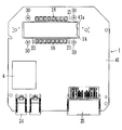
- the figure explaining the relationship between the voltage drop amount of an auxiliary battery, the minimum of operable temperature, and temperature rise end temperature A plan view of a printed circuit board showing the mounting state of each component constituting the in-vehicle emergency call device on the printed circuit board
- the back view which looked at the printed circuit board shown in FIG. 7A from the arrow VIIB direction Front view of the printed circuit board shown in FIG.
- the side view which looked at the printed circuit board shown in FIG. 7A from the arrow VIIE direction 7A is a perspective view of the printed circuit board shown in FIG. 7A.
- the in-vehicle emergency call device 1 (electronic device) can be mounted on a vehicle, and includes a signal detection unit 2, a control circuit 3 (control unit), and an emergency call communication circuit 4.
- the term “installable on the vehicle” includes both a mode in which the vehicle is mounted in a fixed state and a mode in which the vehicle is detachably mounted on the vehicle.
- the collision sensor 5 is provided in a predetermined part of the vehicle body such as the front part of the vehicle, and outputs a sensor signal to the notification signal output unit 6 when it reacts to the collision of the vehicle in response to the collision of the vehicle.
- the reporting signal output unit 6 is, for example, an airbag ECU (Electronic Control Unit), and outputs a normal signal to the signal detection unit 2 as a pulse signal during a period in which no sensor signal is input from the collision sensor 5.
- the notification signal output unit 6 outputs a notification signal different from the normal signal to the signal detection unit 2 by a pulse signal, and an airbag (not shown). To control the driver and passengers from the impact of collision.
- the signal detection unit 2 detects the pulse signal input from the notification signal output unit 6, detects the interval between edges where the level of the pulse signal changes between high and low (high, low pulse duration), etc.
- a detection signal capable of specifying the detection result is output to the control circuit 3.
- a main battery 7 which is a battery mounted on the vehicle side supplies power for operation to the in-vehicle emergency call device 1. The configuration of the power supply system in the in-vehicle emergency call device 1 will be described later with reference to FIG.
- the control circuit 3 is composed mainly of a microcomputer composed of a CPU, ROM, RAM, etc., and executes an operation program stored in the ROM, thereby controlling the overall operation of the in-vehicle emergency call device 1.
- the control circuit 3 monitors the input of the IG signal and the ACC signal from the vehicle switch 8 in the low power consumption state when the IG (ignition) and the ACC (accessory) are in the off state, and the input of the IG signal and the ACC signal is performed. By determining, switching of the IG and ACC from the off state to the on state is determined.
- the control circuit 3 analyzes the detection signal so that the pulse signal output from the notification signal output unit 6 is a notification signal or a normal signal. It is determined whether or not there is a vehicle collision.
- the control circuit 3 determines that the pulse signal output by the notification signal output unit 6 is a notification signal, that is, the vehicle has collided, the control circuit 3 outputs an emergency notification execution instruction to the emergency notification communication circuit 4.
- the emergency call communication circuit 4 has a telephone function (a transmission function for transmitting to a communication network, an incoming function for receiving from a communication network, a voice call function for performing a voice call, a data communication function for performing data communication, etc.), and a control circuit.
- a telephone function a transmission function for transmitting to a communication network, an incoming function for receiving from a communication network, a voice call function for performing a voice call, a data communication function for performing data communication, etc.
- an emergency call is made using the telephone function.
- the emergency call communication circuit 4 uses the GPS positioning, for example, the current position of the vehicle specified by the current position specifying unit (not shown), or the vehicle identification information registered in advance that can specify the vehicle.
- an emergency call signal including (vehicle number, vehicle user, etc.) to a center device 9 of an external organization registered in advance via a wide area communication network (including a mobile communication network and a fixed communication network). Make an emergency call.
- the center device 9 When the center device 9 receives the emergency call signal transmitted from the in-vehicle emergency call device 1 via the wide area communication network, the center device 9 notifies the operator of the external organization of the occurrence of the emergency call. From then on, the operator will receive necessary assistance and provide necessary assistance. There are various forms of assistance performed between an operator and a user (driver). For example, the in-vehicle emergency call device 1 transmits (calls) to the center device 9 to connect a telephone line, and the in-vehicle emergency call device 1 transmits the above-described current vehicle position and vehicle identification information to the center device 9.
- the telephone line may be temporarily disconnected, and the center device 9 may call (call back) the in-vehicle emergency call device 1 to reconnect the telephone line to make a voice call, or may be connected without disconnecting the telephone line.
- the center device 9 may call (call back) the in-vehicle emergency call device 1 to reconnect the telephone line to make a voice call, or may be connected without disconnecting the telephone line.
- the emergency call communication circuit 4 when an emergency call execution instruction is input from the control circuit 3 and the emergency call is started, the emergency call communication circuit 4 is in an operation state of data communication, voice call, outgoing call or incoming call waiting. Or a status notification signal that can specify whether or not the emergency call is finished is output to the control circuit 3.
- the control circuit 3 analyzes the status notification signal input from the emergency call communication circuit 4 so as to notify the emergency call whether the emergency call communication circuit 4 is performing data communication, voice call, or standby. It is possible to specify whether or not the processing has ended.
- the emergency call communication circuit 4 may voluntarily output a state notification signal to the control circuit 3 on a voluntary basis, or may receive a state notification upon receiving a state inquiry signal from the control circuit 3 periodically. A signal may be output to the control circuit 3. Further, the emergency call communication circuit 4 may output a state notification signal to the control circuit 3 at the timing when the operation state is switched.
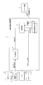
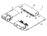
- components and the like constituting the in-vehicle emergency call device 1 are mounted on a printed circuit board 11 (circuit board).
- the power supplied from the main battery 7 is stepped down by the main battery power circuit 12, the power is supplied to the control circuit 3 and the emergency call communication circuit 4 via the main power switch 13 (MPS-SW).
- the auxiliary battery 14 (battery) is a backup power source for the main battery 7 described above.
- the auxiliary battery 14 is miniaturized from the viewpoint of being incorporated in the in-vehicle emergency call device 1, and it is desirable that the number of used cells is small.
- the lithium ion battery has 4 [V] ⁇ 1 cell
- the nickel hydrogen battery has 1.2 [V] ⁇ 3 or 4 cells
- the manganese dioxide lithium battery has 3 [V] ⁇ 1 cell.
- these auxiliary batteries 14 have a characteristic that the internal resistance increases when the in-vehicle environment is low temperature or deteriorates with the passage of years of use, and the power supply voltage is generally lowered.
- the auxiliary battery 14 is built in the in-vehicle emergency call device 1 so that the operator can replace it.
- the auxiliary battery power supply circuit 15 is connected to the auxiliary battery 14 and converts (boosts) the auxiliary power supply voltage supplied from the auxiliary battery 14. That is, the auxiliary battery power supply circuit 15 converts the auxiliary power supply voltage supplied from the auxiliary battery 14 to generate a boosted voltage of 4.8 [V], and the generated boosted voltage is supplied to the main power switch 13. Via the control circuit 3 and the emergency call communication circuit 4. That is, the main power switch 13 is a 2-input / 1-output multiplexer, and switching control thereof is performed by the control circuit 3.
- the voltage of the auxiliary battery power supply circuit 15 is in the range of the operating voltage (for example, 3 to 5 [V]) of each functional block.
- a heater resistor 16 (heating element) is disposed in the vicinity of the auxiliary battery 14.
- the heater resistor 16, the main battery power supply circuit 12 and the first power switch 17 (the first power supply path forming unit, 1 st PS-SW) or via the power supply circuit 15 and the second power supply switch for the auxiliary battery, 18 (second power supply path formation, 2 nd PS-SW) is a power supply via the supplied.
- the heater resistor 16 is used to heat the auxiliary battery 14 when the vehicle is in a low temperature environment or to confirm the function of the auxiliary battery 14. Heat generated by the heater resistor 16 is transmitted to the auxiliary battery 14 via the heat transfer mechanism 19.
- a temperature detection thermistor 20 (temperature detection unit) is disposed in the vicinity of the auxiliary battery 14, and a temperature detection thermistor 21 is also disposed in the vicinity of the heater resistor 16.
- the sensor signal of the thermistor 20 is input to the control circuit 3.
- the thermistor 21 is incorporated in a heating protection circuit 22 that operates to cut off the power supply path to the heater resistor 16 when the heater resistor 16 is heated excessively.
- the overheat protection circuit 22 performs an overheat protection operation by opening the normally closed switch 22S disposed between the first and second power switches 17 and 18 and the heater resistor 16.
- the main power switch 13 and the first and second power switches 17 and 18 are constituted by transistors (semiconductor switches) such as MOSFETs, for example.
- the input terminal of the control circuit 3 is connected to the positive terminals of the main battery 7 and the auxiliary battery 14, and these power supply voltages are A / D converted and read (after being divided as required).
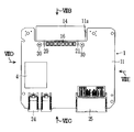
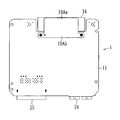
- the printed circuit board 11 has a generally rectangular shape, and a horizontally-long rectangular cutout portion 11a is formed on the back side (FIG. 7A, upper side).
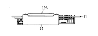
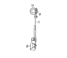
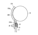
- a battery holder 19A battery holder made of metal (for example, aluminum or the like) forming a heat transfer mechanism 19 (heat transfer member) is attached to the notch 11a.
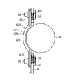
- the auxiliary battery 14 has a cylindrical shape, and the battery holder 19A has a holding portion 19Aa that forms a curved surface that matches the arc of the auxiliary battery 14 so as to hold a part of the outer peripheral surface of the cylinder along the longitudinal direction. (See FIG. 9).
- the holding portion 19Aa is followed by a horizontally long attachment portion 19Ab.
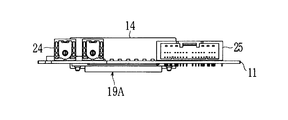
- the attachment portion 19Ab is in contact with the back surface of the printed circuit board 11, and both ends of the attachment portion 19Ab are connected to the surface side of the printed circuit board 11 by screws 30. (See FIGS. 7A and 8B).
- a plurality of heater resistors 16 made of chip resistors are arranged in the longitudinal direction of the notch portion 11a.
- a heat transfer sheet 19 ⁇ / b> B heat transfer material
- the heat transfer sheet 19B is, for example, a silicon-based elastic material, and is in close contact with the battery holder 19A, the auxiliary battery 14, and the printed board 11.
- the heater resistor 16 disposed on the front surface side of the printed circuit board 11 and the back surface corresponding to the position, that is, the attachment portion 19Ab of the battery holder 19A are in contact via the heat transfer sheet 19B.
- a through hole 23 made of a copper foil is formed between the two portions.
- the thermistors 20 and 21 are arranged on both sides of the heater resistor 16, respectively. These thermistors 20 and 21 are in a positional relationship so as to equally detect the heat generation of the heater resistor 16 and are close to the attachment portion 19Ab of the battery holder 19A disposed on the back side of the printed circuit board 11. Is arranged. However, since the thermistor 20 is provided for the control circuit 3 to detect the temperature of the auxiliary battery 14, how much the actual temperature of the auxiliary battery 14 depends on the temperature detected by the thermistor 20 at this position. Correlation data indicating whether or not is obtained in advance, and the control circuit 3 performs temperature detection.
- the printed circuit board 11 includes a module of the emergency call communication circuit 4, a connector 24 for connecting an antenna to the emergency call communication circuit 4, an interface connector 25 for the control circuit 3 to communicate with the vehicle side, and the like. Has been.
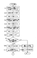
- FIG. 3 as an initial state, the main power switch 13 is connected to the main battery 7 side, and the first and second power switches 17 and 18 are both OFF (S1). Control circuit 3.
- the thermistor 20 detects the temperature of the auxiliary battery 14 (S2), and then checks (1) the voltage of the auxiliary battery 14 (S3).
- the control circuit 3 controls ON / OFF of the second power switch 18 by the PWM signal so that the current supplied to the heater resistor 16 by the power from the auxiliary battery 14 becomes the current value A ( S4).
- the voltage of the auxiliary battery 14 is checked (2) (S5).
- the control circuit 3 controls the ON / OFF of the second power switch 18 by the PWM signal so that the current supplied to the heater resistor 16 becomes the current value B (> A) (S6).
- the voltage of the auxiliary battery 14 is checked (3) (S7).
- the second power switch 18 is turned off (S8).
- the control circuit 3 determines whether or not the difference between the voltages of the auxiliary battery 14 detected in steps S3, S5, and S7 is within a threshold corresponding to the temperature of the auxiliary battery 14 detected in step S2. (S9). If it is within the threshold value (YES), it is determined that the auxiliary battery 14 is valid (function is normal) (S10), and the processes after step S11 are executed. On the other hand, if it is not within the threshold (NO), it is determined that the auxiliary battery 14 is invalid (failure or life) (S12), the fact that the auxiliary battery 14 is invalid is notified (S13), and the process is terminated. .
- the in-vehicle emergency call device 1 is provided with a warning indicator (LED lamp or the like), the notification is turned on. Further, for example, if the in-vehicle emergency call device 1 is connected to a vehicle ECU (Electronic Control Unit) or the like via an in-vehicle LAN or the like, a message signal is transmitted to the body ECU and the vehicle instrument panel May be displayed.
- a warning indicator LED lamp or the like
- the current A shown in FIG. 5A and the current B shown in FIG. 5B have a relationship (A ⁇ B).
- the determination line set for each current value is based on the temperature characteristics of the auxiliary battery 14. For example, in a low temperature region below ⁇ 10 ° C., the amount of voltage drop increases rapidly, and there is a possibility that sufficient power cannot be supplied.
- the determination accuracy is maintained by performing the determination based on the voltage drop amount when the output current is large.
- a determination line may be set for one current value.
- step S9 when referring to the amount of voltage change in order to determine whether or not the auxiliary battery 14 is abnormal, it is not always necessary to control the ON / OFF of the second power switch 18 with the PWM signal. For example, from the voltage of the auxiliary battery 14 when the second power switch is turned off, abnormality determination is performed based on the amount of voltage drop of the auxiliary battery 14 when the second power switch is turned on (continuously). Also good.
- the auxiliary battery 14 is valid, the lower limit of the operable temperature of the auxiliary battery 14 is estimated from the voltage difference obtained in step S9 (S11). Then, the temperature of the auxiliary battery 14 and the temperature of the heater resistor 16 are detected from the thermistor 21 (S14), and it is determined whether or not the auxiliary battery 14 needs to be preheated in the subsequent step S15.
- the judgment conditions here are: (Temperature of auxiliary battery 14) ⁇ (Operating temperature) and (Temperature of heater resistor 16) ⁇ (Overheat protection temperature) It is. If this condition is satisfied, it is determined that the auxiliary battery 14 needs to be preheated (YES).
- step S16 the temperature rise end temperature of the auxiliary battery 14 is determined from the operable temperature estimated in step S11. Then, the voltage of the main battery 7 is checked to determine whether or not it is normal (S17). If it is normal (YES), steps S18 to S25 are executed. If it is abnormal (NO), steps S26 to S34 are executed.
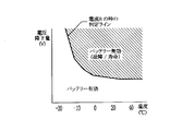
- step S11 the relationship between the voltage difference in step S11 and the lower limit of the operable temperature and the relationship between the temperature rise end temperature in step S16 will be described.
- FIG. 6 it is assumed that the amount of voltage drop during a certain measurement is in the effective area of the auxiliary battery 14 indicated by dots in the drawing.
- the auxiliary battery 14 cannot be used as it is (here, the “operating limit” does not depend on the temperature).
- the amount of voltage drop corresponding to the “operation limit” changes according to the voltage of the auxiliary battery 14).
- the temperature characteristic of the auxiliary battery 14 is taken into consideration to estimate the voltage drop vs. temperature characteristic curve. Then, the intersection of the characteristic curve and the system operation limit line corresponds to the “lower limit of operable temperature”. The temperature obtained by adding a margin to the lower limit becomes the “temperature rise end temperature” in step S16 (open dots in FIG. 6).
- the internal resistance value of the auxiliary battery 14 is calculated based on the voltage drop amount and the current values A and B, and valid / invalid determination is performed based on the temperature characteristics of the internal resistance, or the estimated voltage drop amount And the lower limit of the operable temperature is calculated.
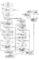
- step S18 the operating state of the system (the in-vehicle emergency call device 1) is checked, and the current that can be supplied to the heater resistor 16 is calculated. If the suppliable current exceeds 0 A (S19: YES), the heater resistor 16 is energized via the first power switch 17. Also here, the first power switch 17 is turned on / off by the PWM signal so that the energization current to the heater resistor 16 is in a range not exceeding the suppliable current (S20).
- the voltage of the main battery 7 is checked (S21), and it is determined whether or not the main battery 7 has a current supply capability (S22). If there is current supply capability (YES), the temperature of the auxiliary battery 14 and the temperature of the heater resistor 16 are detected (S23), and the following condition judgment is performed (S24). (Temperature of auxiliary battery 14) ⁇ (temperature rise end temperature) and (temperature of heater resistor 16) ⁇ (overheat protection temperature) If “YES” is determined here, the process returns to step S18 to repeat the above processing. If “NO” is determined in any of steps S19, S22, and S24, the first power switch 17 is turned off to stop energization of the heater resistor 16 (S25). Then, the process returns to step S14 as necessary.
- step S17 the main power switch 13 is switched to the auxiliary battery 14 side (S26). This process may be controlled by hardware.
- the same processing and determination as in steps S18 and S19 are performed (S27 and S28). If the suppliable current exceeds 0 A (S28: YES), the heater resistor 16 is energized via the second power switch 18. Do. That is, the second power switch 18 is turned on / off by the PWM signal so that the energization current to the heater resistor 16 is in a range that does not exceed the supplyable current (S29).
- the voltage of the auxiliary battery 14 is checked (S30), and it is determined whether or not the auxiliary battery 14 has a current supply capability (S31). If there is current supply capability (YES), the same processing and determination as in steps S23 and S24 are performed (S32 and S33). If “YES” is determined in the step S33, the process returns to the step S27 to repeat the above processing. If “NO” is determined in any of steps S28, S31, and S33, the second power switch 18 is turned off to stop energization of the heater resistor 16 (S34). Then, the process returns to step S14 as necessary.
- step S15 determines “NO” in step S15 (when the auxiliary battery 14 does not require preheating)
- the state of the main battery 7 is monitored in the same manner as in step S14 (S35).
- the second power switches 17 and 18 remain OFF (S36).
- step S37 determines whether abnormal (NO) is abnormal (NO) or not.
- the auxiliary battery 14 built in the in-vehicle emergency call device 1 as a standby power source for the main battery 7 and the heater resistor 16 for heating the auxiliary battery 14 are printed circuit boards. 11 is provided with a heat transfer mechanism 19 for transmitting heat generated by the heater resistor 16 to the auxiliary battery 14 battery. Then, the auxiliary battery 14 is detachably fixed on the printed circuit board 11 via the heat transfer mechanism 19. Therefore, the heat generated by the heater resistor 16 can be conducted to the auxiliary battery 14 via the heat transfer mechanism 19 to heat the auxiliary battery 14, and the auxiliary battery 14 can be easily detached from the heat transfer mechanism 19 as necessary. Can be replaced.
- the heater resistor 16 is composed of a plurality of chip resistors and arranged on the front surface side of the printed circuit board 11, and the heat transfer mechanism 19 is disposed on the other back surface side of the printed circuit board 11. Then, a through hole 23 is formed at a position corresponding to the portion where the heater resistor 16 is disposed on the printed circuit board 11 and the portion where the heat transfer member is disposed, and is transmitted from the heater resistor 16 via the through hole 23. Conducts heat to the heat mechanism 19.
- the heater resistor 16 and the heat transfer mechanism 19 can be disposed compactly on both sides of the printed circuit board 11, and the heat transfer efficiency can be maintained well by conducting heat conduction between the two via the through hole 23. Further, the heating mode of the auxiliary battery 14 can be easily and inexpensively adjusted by adjusting the size and the number of the chip resistors. In this case, since the heater resistor 16 is disposed along the longitudinal direction of the auxiliary battery 14 having a cylindrical outer shape, the auxiliary battery 14 can be efficiently heated.
- the heat transfer mechanism 19 includes a metal battery holder 19A having a mounting portion 19Ab on one end side fixed to the printed circuit board 11 and a holding portion 19Aa on the other end side, the printed circuit board 11, the battery holder 19A, and an auxiliary device.
- a heat transfer sheet 19B interposed between the batteries 14 is provided.
- the heat generated by the heater resistor 16 can be conducted with high efficiency through the route of the printed circuit board 11 ⁇ the heat transfer sheet 19B and the battery holder 19A ⁇ the auxiliary battery 14.
- the heat transfer sheet 19B is pressed and used to bring the heat transfer surface into close contact with each other, maintaining a good heat transfer efficiency and at the same time absorbing the rattling of the auxiliary battery 14 due to the vibration of the vehicle. Occurrence can be suppressed.
- the thermistor 20 for detecting the temperature of the auxiliary battery 14 is arranged on the printed circuit board 11 close to the heat transfer mechanism 19, the temperature of the auxiliary battery 14 can be detected with higher accuracy.
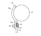
- the second embodiment uses a battery holder 31 (battery holder, heat transfer member) instead of the battery holder 19A and the heat transfer sheet 19B of the first embodiment.
- the battery holder 31 is made of a member having elasticity (for example, heat transfer rubber, resin such as ABS, elastomer, etc.), and includes a holding portion 31a and a mounting portion 31b having shapes corresponding to the holding portion 19Aa and the mounting portion 19Ab. ing.
- the attachment portion 31b is directly screwed to the printed circuit board 11 with a screw 30, and the auxiliary battery 14 is in direct contact with the holding portion 31a. Then, the auxiliary battery 14 is pressed from above (in the front view) by the back surface of the cover when the cover of the exterior case is attached, and is held in a state of being pressed against the holding portion 31a.
- the battery holder 31 is formed of an elastic member and the heat transfer member is a single unit, the battery holder 31 can be formed of fewer parts and can be easily attached to the printed circuit board 11. Can be done.
- the heater resistor 16 is disposed on the back surface side of the printed circuit board 32, and the copper surface is disposed on the back surface on which the heater resistor 16 and the mounting portion 19 ⁇ / b> Ab of the battery holder 19 ⁇ / b> A are disposed.
- a foil (pattern) 33 is disposed (the through hole 23 is not formed). Therefore, the heat generated by the heater resistor 16 is conducted to the auxiliary battery 14 via the copper foil 33 ⁇ the attachment portion 19Ab ⁇ the holding portion 19Aa.
- the same effect as that of the first embodiment can be obtained.
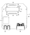
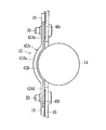
- the shape of a printed circuit board 41 (circuit board) is different from that in the first embodiment. That is, a rectangular opening 41a is formed in place of the notch 11a. Then, the shape of the battery holder 42A (heat transfer member, battery holder) forming the heat transfer mechanism 42 is as shown in FIG. 13, and the front end and the rear of the holder 42Aa having a curved surface along the outer shape of the auxiliary battery 14 are formed. A front attachment portion 42Af and a rear attachment portion 42Ar are provided at the end portions (the lower end portion and the upper end portion in FIG. 13), respectively.
- the heat transfer sheet 42B (heat transfer member) is interposed between the battery holder 42A and the printed circuit board 41 and the auxiliary battery 14, and the battery holder 42A includes a front side attachment portion 42Af, a rear side attachment portion 42Ar, Are each screwed by a screw 30.
- the heater resistor 16 is disposed along the longitudinal direction of the opening 41a on the surface side of the printed circuit board 11 where the front attachment portion 42Af and the rear attachment portion 42Ar are located. Further, through holes 44f and 44r are formed in portions of the printed circuit board 41 corresponding to them as in the first embodiment. The heat generated by the heater resistor 16 is transmitted to the front mounting portion 42Af and the rear mounting portion 42Ar on the back side through the through holes 44f and 44r.
- the battery holder 42A is configured in such a shape that both end sides thereof are fixed to the printed circuit board 41 and the holding portion 42Aa is provided between both ends, and the heater resistor 16 is connected to the printed circuit board 41. On the surface, it was arranged on both sides of the auxiliary battery 14 along the longitudinal direction. Therefore, the auxiliary battery 14 can be heated more efficiently.
- another thermistor 21 is indicated by a broken line.
- the heater resistor 16 is configured to be energized independently by a group (for example, 16F) disposed on the front side of the auxiliary battery 14 and a group (for example, 16R) disposed on the rear side, respectively.
- a group for example, 16F
- 16R group disposed on the rear side, respectively.
- the overheat protection circuit 22 in order for the overheat protection circuit 22 to perform an overheat protection operation in hardware, if it is necessary to detect the temperature of each group independently, another thermistor 21 is disposed as shown by the broken line.
- the configuration of the third embodiment is applied to the configuration of the fourth embodiment, and the outer shape of the printed circuit board 45 is the same as that of the printed circuit board 41.
- the heater resistor 16 is disposed on the back side of the printed circuit board 45, and the heater resistor 16 and mounting portions 42Af and 42Ar of the battery holder 42A are disposed in place of the through holes 44f and 44r. Copper foils 46f and 46r are disposed on the rear surface. Therefore, the heat generated by the heater resistor 16 is conducted to the auxiliary battery 14 via the copper foils 46f and 46r ⁇ the attachment portions 42Af and 42Ar ⁇ the holding portion 42Aa.
- the same effects as those of the third and fourth embodiments can be obtained.
- control circuit 3 does not necessarily need to confirm the power supply capability on the side of the main battery 7 when the temperature of the auxiliary battery 14 falls below the operable temperature. 16 may be energized.
- the heating element may be other than a chip resistor such as the heater resistor 16.
- the heat transfer sheets 19B and 42B may have a structure in which a portion that comes into contact with the printed circuit boards 11, 32, 41, and 45 and a portion that comes into contact with the auxiliary battery 14 are separate, and are made of materials having different elasticity and thickness. May be.
- the thermistor 21 and the overheat protection circuit 22 may be provided as necessary.
- the battery holder holding portion may be cylindrical and an auxiliary battery may be inserted therein.
- three or more heater resistors 16 may be provided.
- the heat transfer mechanism 42 may be configured only by a battery holder made of an elastic member as in the second embodiment.
Landscapes
- Engineering & Computer Science (AREA)
- Chemical & Material Sciences (AREA)
- Chemical Kinetics & Catalysis (AREA)
- Electrochemistry (AREA)
- General Chemical & Material Sciences (AREA)
- Manufacturing & Machinery (AREA)
- Physics & Mathematics (AREA)
- Electromagnetism (AREA)
- Microelectronics & Electronic Packaging (AREA)
- Secondary Cells (AREA)
- Battery Mounting, Suspending (AREA)
Priority Applications (3)
| Application Number | Priority Date | Filing Date | Title |
|---|---|---|---|
| DE112014006126.3T DE112014006126B4 (de) | 2014-01-08 | 2014-12-24 | Platinenanordnung |
| US15/109,937 US10211435B2 (en) | 2014-01-08 | 2014-12-24 | Circuit board structure |
| CN201480072571.4A CN105900278B (zh) | 2014-01-08 | 2014-12-24 | 电路基板构造 |
Applications Claiming Priority (2)
| Application Number | Priority Date | Filing Date | Title |
|---|---|---|---|
| JP2014-001626 | 2014-01-08 | ||
| JP2014001626A JP6349731B2 (ja) | 2014-01-08 | 2014-01-08 | 回路基板構造 |
Publications (1)
| Publication Number | Publication Date |
|---|---|
| WO2015104771A1 true WO2015104771A1 (ja) | 2015-07-16 |
Family
ID=53523628
Family Applications (1)
| Application Number | Title | Priority Date | Filing Date |
|---|---|---|---|
| PCT/JP2014/006412 Ceased WO2015104771A1 (ja) | 2014-01-08 | 2014-12-24 | 回路基板構造 |
Country Status (5)
| Country | Link |
|---|---|
| US (1) | US10211435B2 (enExample) |
| JP (1) | JP6349731B2 (enExample) |
| CN (1) | CN105900278B (enExample) |
| DE (1) | DE112014006126B4 (enExample) |
| WO (1) | WO2015104771A1 (enExample) |
Cited By (1)
| Publication number | Priority date | Publication date | Assignee | Title |
|---|---|---|---|---|
| EP3157075A1 (fr) * | 2015-10-16 | 2017-04-19 | BUBENDORFF Société Anonyme | Dispositif d'alimentation ou de commande d'un moteur électrique |
Families Citing this family (10)
| Publication number | Priority date | Publication date | Assignee | Title |
|---|---|---|---|---|
| CN106887562B (zh) * | 2015-12-15 | 2020-12-04 | 小米科技有限责任公司 | 电芯的保护主板、电子终端和电子终端用电芯的组装方法 |
| WO2018094418A1 (en) * | 2016-11-21 | 2018-05-24 | Sanmina Corporation | Using a heating element to manage energy storage cell equivalent series resistance (esr) |
| KR102307298B1 (ko) * | 2017-08-30 | 2021-09-30 | 주식회사 엘지화학 | 긴급 전화 전원 공급용 배터리 모듈 |
| DE102018104935B4 (de) * | 2018-03-05 | 2023-02-09 | Dr. Ing. H.C. F. Porsche Aktiengesellschaft | Verfahren, System und Batteriemodul zur Kühlung einer mittels Federwirkung kontaktierten Leistungselektronik |
| JP2019192486A (ja) * | 2018-04-25 | 2019-10-31 | 株式会社オートネットワーク技術研究所 | 蓄電ユニット |
| CN108711662B (zh) | 2018-05-22 | 2020-05-05 | 宁德时代新能源科技股份有限公司 | 一种电池组加热装置与控制方法 |
| CN108705943B (zh) | 2018-05-22 | 2020-05-05 | 宁德时代新能源科技股份有限公司 | 一种电池组加热装置与控制方法 |
| CN209071559U (zh) * | 2018-11-15 | 2019-07-05 | 宁德时代新能源科技股份有限公司 | 电池监控单元及电池包 |
| CN113960445B (zh) * | 2021-09-28 | 2024-07-19 | 蓝芯存储技术(赣州)有限公司 | 一种新的bga测试方法及pcba板 |
| CN116826213B (zh) * | 2023-08-29 | 2023-11-17 | 深圳市岳松科技有限公司 | 一种具有电池温控监测的bms保护板 |
Citations (5)
| Publication number | Priority date | Publication date | Assignee | Title |
|---|---|---|---|---|
| JP2002008604A (ja) * | 2000-06-21 | 2002-01-11 | Sony Corp | 電子機器 |
| JP2003229110A (ja) * | 2002-01-31 | 2003-08-15 | Sanyo Electric Co Ltd | 車両用のバッテリー装置 |
| JP2004111370A (ja) * | 2002-08-29 | 2004-04-08 | Matsushita Electric Ind Co Ltd | 電池の熱制御装置 |
| JP2005295668A (ja) * | 2004-03-31 | 2005-10-20 | Sanyo Electric Co Ltd | 車両用の電源装置 |
| JP2007274373A (ja) * | 2006-03-31 | 2007-10-18 | Casio Hitachi Mobile Communications Co Ltd | 電子機器 |
Family Cites Families (9)
| Publication number | Priority date | Publication date | Assignee | Title |
|---|---|---|---|---|
| JPH09213459A (ja) | 1996-02-02 | 1997-08-15 | Kojundo Chem Lab Co Ltd | バッテリー加熱装置 |
| TW501293B (en) * | 2001-01-06 | 2002-09-01 | Acer Inc | Method and device to raise the battery efficiency of portable electronic device |
| JP4020650B2 (ja) * | 2002-01-30 | 2007-12-12 | 三洋電機株式会社 | 車両用のバッテリー装置 |
| US20050074666A1 (en) * | 2002-08-29 | 2005-04-07 | Hirokazu Kimiya | Heat control device for battery |
| JP2010054538A (ja) * | 2008-08-26 | 2010-03-11 | Sea&Sea Sunpak Co Ltd | ストロボ匡体収納電池の放熱装置 |
| JP2012204129A (ja) * | 2011-03-25 | 2012-10-22 | Hitachi Maxell Ltd | 組電池 |
| EP2667076B1 (en) * | 2011-10-31 | 2017-04-19 | Panasonic Intellectual Property Management Co., Ltd. | Secondary battery unit |
| KR101431720B1 (ko) * | 2011-12-13 | 2014-08-22 | 주식회사 엘지화학 | 신규한 구조의 스위칭 보드 및 그것을 포함하고 있는 전지모듈 |
| EP2736100B1 (de) * | 2012-11-22 | 2017-06-21 | Samsung SDI Co., Ltd. | Elektronikeinheit mit Temperaturmesseinrichtung für ein Batteriesystem |
-
2014
- 2014-01-08 JP JP2014001626A patent/JP6349731B2/ja active Active
- 2014-12-24 WO PCT/JP2014/006412 patent/WO2015104771A1/ja not_active Ceased
- 2014-12-24 DE DE112014006126.3T patent/DE112014006126B4/de active Active
- 2014-12-24 CN CN201480072571.4A patent/CN105900278B/zh active Active
- 2014-12-24 US US15/109,937 patent/US10211435B2/en active Active
Patent Citations (5)
| Publication number | Priority date | Publication date | Assignee | Title |
|---|---|---|---|---|
| JP2002008604A (ja) * | 2000-06-21 | 2002-01-11 | Sony Corp | 電子機器 |
| JP2003229110A (ja) * | 2002-01-31 | 2003-08-15 | Sanyo Electric Co Ltd | 車両用のバッテリー装置 |
| JP2004111370A (ja) * | 2002-08-29 | 2004-04-08 | Matsushita Electric Ind Co Ltd | 電池の熱制御装置 |
| JP2005295668A (ja) * | 2004-03-31 | 2005-10-20 | Sanyo Electric Co Ltd | 車両用の電源装置 |
| JP2007274373A (ja) * | 2006-03-31 | 2007-10-18 | Casio Hitachi Mobile Communications Co Ltd | 電子機器 |
Cited By (2)
| Publication number | Priority date | Publication date | Assignee | Title |
|---|---|---|---|---|
| EP3157075A1 (fr) * | 2015-10-16 | 2017-04-19 | BUBENDORFF Société Anonyme | Dispositif d'alimentation ou de commande d'un moteur électrique |
| FR3042657A1 (fr) * | 2015-10-16 | 2017-04-21 | Bubendorff | Dispositif d'alimentation ou de commande d'un moteur electrique |
Also Published As
| Publication number | Publication date |
|---|---|
| US20160336561A1 (en) | 2016-11-17 |
| CN105900278A (zh) | 2016-08-24 |
| JP2015130288A (ja) | 2015-07-16 |
| DE112014006126B4 (de) | 2022-09-29 |
| JP6349731B2 (ja) | 2018-07-04 |
| DE112014006126T5 (de) | 2016-10-27 |
| CN105900278B (zh) | 2019-07-23 |
| US10211435B2 (en) | 2019-02-19 |
Similar Documents
| Publication | Publication Date | Title |
|---|---|---|
| JP6349731B2 (ja) | 回路基板構造 | |
| JP6221749B2 (ja) | 電子機器 | |
| KR102283791B1 (ko) | 배터리 보호 장치 | |
| JP5208149B2 (ja) | 保護回路、及び電池パック | |
| JP2018073691A (ja) | 車両用のバッテリ監視装置及び車両用のバッテリ監視システム | |
| WO2018092562A1 (ja) | 車両用のバッテリ監視装置及び車両用のバッテリ監視システム | |
| US20060261843A1 (en) | Device for a data and energy management in a vehicle | |
| US20140113166A1 (en) | Safety device for arrangement in a battery cell of a lithium-ion battery, lithium-ion battery cell with safety device | |
| JP2019085103A (ja) | モータサイクル用の加熱ハンドグリップ | |
| CN110326184A (zh) | 车载用电池的保护电路 | |
| US20090209225A1 (en) | Emergency Call System | |
| CN106029412B (zh) | 辐射加热器装置的控制系统 | |
| US11458913B2 (en) | Wiring module including a power supply branch part | |
| JP6642323B2 (ja) | コネクタ装置 | |
| JP2008130007A (ja) | 車載緊急通報装置 | |
| WO2014184920A1 (ja) | 電池監視装置、電池監視基板、電池モジュール、電池システム | |
| JP2007195021A (ja) | 携帯端末装置 | |
| EP4299387A1 (en) | Power system | |
| CN103359015B (zh) | 机动车辆的应急系统 | |
| EP4299386A1 (en) | Power system | |
| JP7593079B2 (ja) | 電子回路基板、及び電子機器 | |
| JP2002216924A (ja) | 回転コネクタ | |
| WO2014061665A1 (ja) | 電子機器用充電台 | |
| WO2024156503A1 (en) | System for operating a heating device of a camera for a motor vehicle | |
| KR20250089917A (ko) | 배기가스 후처리 장치 |
Legal Events
| Date | Code | Title | Description |
|---|---|---|---|
| 121 | Ep: the epo has been informed by wipo that ep was designated in this application |
Ref document number: 14877578 Country of ref document: EP Kind code of ref document: A1 |
|
| WWE | Wipo information: entry into national phase |
Ref document number: 15109937 Country of ref document: US |
|
| WWE | Wipo information: entry into national phase |
Ref document number: 112014006126 Country of ref document: DE |
|
| 122 | Ep: pct application non-entry in european phase |
Ref document number: 14877578 Country of ref document: EP Kind code of ref document: A1 |