WO2015098800A1 - 振動体の駆動回路、振動型アクチュエータ、撮像装置、画像生成装置、及び塵埃除去装置 - Google Patents
振動体の駆動回路、振動型アクチュエータ、撮像装置、画像生成装置、及び塵埃除去装置 Download PDFInfo
- Publication number
- WO2015098800A1 WO2015098800A1 PCT/JP2014/083841 JP2014083841W WO2015098800A1 WO 2015098800 A1 WO2015098800 A1 WO 2015098800A1 JP 2014083841 W JP2014083841 W JP 2014083841W WO 2015098800 A1 WO2015098800 A1 WO 2015098800A1
- Authority
- WO
- WIPO (PCT)
- Prior art keywords
- transformer
- inductance
- drive circuit
- winding coil
- circuit
- Prior art date
- Legal status (The legal status is an assumption and is not a legal conclusion. Google has not performed a legal analysis and makes no representation as to the accuracy of the status listed.)
- Ceased
Links
Images


Classifications
-
- H—ELECTRICITY
- H02—GENERATION; CONVERSION OR DISTRIBUTION OF ELECTRIC POWER
- H02N—ELECTRIC MACHINES NOT OTHERWISE PROVIDED FOR
- H02N2/00—Electric machines in general using piezoelectric effect, electrostriction or magnetostriction
- H02N2/0005—Electric machines in general using piezoelectric effect, electrostriction or magnetostriction producing non-specific motion; Details common to machines covered by H02N2/02 - H02N2/16
- H02N2/0075—Electrical details, e.g. drive or control circuits or methods
-
- G—PHYSICS
- G02—OPTICS
- G02B—OPTICAL ELEMENTS, SYSTEMS OR APPARATUS
- G02B27/00—Optical systems or apparatus not provided for by any of the groups G02B1/00 - G02B26/00, G02B30/00
- G02B27/0006—Optical systems or apparatus not provided for by any of the groups G02B1/00 - G02B26/00, G02B30/00 with means to keep optical surfaces clean, e.g. by preventing or removing dirt, stains, contamination, condensation
-
- G—PHYSICS
- G02—OPTICS
- G02B—OPTICAL ELEMENTS, SYSTEMS OR APPARATUS
- G02B27/00—Optical systems or apparatus not provided for by any of the groups G02B1/00 - G02B26/00, G02B30/00
- G02B27/64—Imaging systems using optical elements for stabilisation of the lateral and angular position of the image
- G02B27/646—Imaging systems using optical elements for stabilisation of the lateral and angular position of the image compensating for small deviations, e.g. due to vibration or shake
-
- H—ELECTRICITY
- H02—GENERATION; CONVERSION OR DISTRIBUTION OF ELECTRIC POWER
- H02N—ELECTRIC MACHINES NOT OTHERWISE PROVIDED FOR
- H02N2/00—Electric machines in general using piezoelectric effect, electrostriction or magnetostriction
- H02N2/0005—Electric machines in general using piezoelectric effect, electrostriction or magnetostriction producing non-specific motion; Details common to machines covered by H02N2/02 - H02N2/16
- H02N2/001—Driving devices, e.g. vibrators
- H02N2/0015—Driving devices, e.g. vibrators using only bending modes
-
- H—ELECTRICITY
- H02—GENERATION; CONVERSION OR DISTRIBUTION OF ELECTRIC POWER
- H02N—ELECTRIC MACHINES NOT OTHERWISE PROVIDED FOR
- H02N2/00—Electric machines in general using piezoelectric effect, electrostriction or magnetostriction
- H02N2/10—Electric machines in general using piezoelectric effect, electrostriction or magnetostriction producing rotary motion, e.g. rotary motors
- H02N2/103—Electric machines in general using piezoelectric effect, electrostriction or magnetostriction producing rotary motion, e.g. rotary motors by pressing one or more vibrators against the rotor
-
- H—ELECTRICITY
- H02—GENERATION; CONVERSION OR DISTRIBUTION OF ELECTRIC POWER
- H02N—ELECTRIC MACHINES NOT OTHERWISE PROVIDED FOR
- H02N2/00—Electric machines in general using piezoelectric effect, electrostriction or magnetostriction
- H02N2/10—Electric machines in general using piezoelectric effect, electrostriction or magnetostriction producing rotary motion, e.g. rotary motors
- H02N2/14—Drive circuits; Control arrangements or methods
- H02N2/142—Small signal circuits; Means for controlling position or derived quantities, e.g. speed, torque, starting, stopping, reversing
-
- H—ELECTRICITY
- H02—GENERATION; CONVERSION OR DISTRIBUTION OF ELECTRIC POWER
- H02N—ELECTRIC MACHINES NOT OTHERWISE PROVIDED FOR
- H02N2/00—Electric machines in general using piezoelectric effect, electrostriction or magnetostriction
- H02N2/10—Electric machines in general using piezoelectric effect, electrostriction or magnetostriction producing rotary motion, e.g. rotary motors
- H02N2/16—Electric machines in general using piezoelectric effect, electrostriction or magnetostriction producing rotary motion, e.g. rotary motors using travelling waves, i.e. Rayleigh surface waves
- H02N2/163—Motors with ring stator
-
- H—ELECTRICITY
- H04—ELECTRIC COMMUNICATION TECHNIQUE
- H04N—PICTORIAL COMMUNICATION, e.g. TELEVISION
- H04N23/00—Cameras or camera modules comprising electronic image sensors; Control thereof
- H04N23/80—Camera processing pipelines; Components thereof
- H04N23/81—Camera processing pipelines; Components thereof for suppressing or minimising disturbance in the image signal generation
- H04N23/811—Camera processing pipelines; Components thereof for suppressing or minimising disturbance in the image signal generation by dust removal, e.g. from surfaces of the image sensor or processing of the image signal output by the electronic image sensor
Definitions
- the present invention relates to a driving circuit for a vibrating body, a vibration type actuator, an imaging device, an image generation device, and a dust removal device.
- the vibration type actuator is configured to apply an alternating voltage to an electro-mechanical energy conversion element coupled to an elastic body to generate high-frequency vibration in the element, and to extract the vibration energy as continuous mechanical motion.
- This is a non-electromagnetic drive actuator.
- the vibration type actuator is used for, for example, autofocus driving of a camera.
- the autofocus drive requires highly accurate positioning control, and position feedback control using a position sensor is performed.
- the control parameter is calculated based on the deviation between the position command value and the position signal detected from the position sensor.
- the speed of the vibration type actuator can be controlled by adjusting the drive frequency, phase difference between the two-phase drive voltage signals applied to the electro-mechanical energy conversion element such as the piezoelectric element, and the drive pulse width as control parameters.
- the vibration amplitude increases as the drive frequency approaches the resonance frequency of the piezoelectric element, and the lens that is the object to be driven can be driven at high speed.
- a rectangular wave-shaped drive frequency signal based on the control parameter is generated by the pulse generator, it is boosted to a predetermined alternating voltage by the drive circuit.
- the drive circuit has a function of boosting the rectangular wave signal input from the pulse generator several times to several tens of times using a coil or a transformer and outputting an alternating voltage of a sine wave.
- the frequency and pulse duty of the signal of the pulse generator are controlled on and off by a switching circuit and adjusted according to the driving frequency.
- the drive circuit using the coil is an LC booster circuit using LC resonance that electrically amplifies a specific frequency signal by the inductance of the coil and the capacitance of the piezoelectric element.
- the boosting rate is generally about 1.5 to 3 times.
- a step-up circuit using a transformer is used when a higher step-up rate is required, and the step-up rate can be freely adjusted by the turn ratio of the primary winding coil and the secondary winding coil of the transformer.
- the boosting ratio is generally used at about 3 to 30 times, and the drive voltage required by the vibrator is mainly as large as about 100 to 500 Vpp.
- a sine wave from which harmonic components are removed can be more effectively created by providing a coil element in series with the piezoelectric element on the primary side or the secondary side of the transformer.
- Patent Document 1 is a piezoelectric vibrator driving circuit that drives a piezoelectric vibrator near a resonance frequency using a one-stone switching circuit, and uses a transformer. By inserting a coil of an appropriate value in series with the piezoelectric vibrator on the secondary side of the transformer, the voltage and current of the piezoelectric vibrator are changed to a sine wave, and the drive frequency is controlled by paying attention to the phase of the current waveform. Is what you do.
- Patent Document 2 provides a vibration wave motor that connects an inductance element to a driving electrode of a vibration wave motor and connects a capacitance element in parallel to the equivalent circuit of the motor to optimize the motor characteristics. It is. As an example, a drive circuit using a transformer is shown.
- Patent Document 3 discloses the following drive circuit. That is, an ultrasonic motor drive circuit described in Patent Document 3 includes an oscillator that generates a high frequency for driving an ultrasonic motor that is an oscillation circuit of a reference frequency, and each switching transistor that forms the drive circuit by receiving the high frequency of the oscillator Has a buffer group for driving. It also has a full-bridge switching transistor that turns on and off high-frequency conduction through a buffer, a transformer for boosting the low voltage of the driving high-frequency power, and a coil for shaping the output waveform of the transformer .
- Patent Document 4 includes a variable control means for duty ratio of high-frequency power applied to a piezoelectric vibrating body that is a rotational drive source of an ultrasonic motor, and compensates for a speed change due to a load variation to thereby control a voltage control chopper circuit ( A drive circuit that does not require a DC-DC conversion circuit) is disclosed. That is, a circuit in which a power supply separation type half bridge is combined is shown as an inverter circuit for supplying high-frequency power to a piezoelectric body. The output pulse of the inverter circuit is applied to the piezoelectric body via a boosting transformer.
- the high frequency power applied to the piezoelectric body is fed back via a step-down transformer, and frequency control means is provided for variably controlling the output frequency of the inverter circuit and correcting fluctuations for load disturbance.
- frequency control means is provided for variably controlling the output frequency of the inverter circuit and correcting fluctuations for load disturbance.
- the output of the pulse width control means for changing the width of the square wave pulse is inputted to the inverter circuit based on the output of the frequency control means and the detection voltage of the vibration state detection means of the piezoelectric body. . It is described that the pulse width of the square wave is increased when the rotation speed is decreased, and the pulse width of the square wave is decreased when the rotation speed is increased.
- Patent Document 5 discloses a drive circuit having an oscillator that outputs a reference signal composed of a pulse train, and a frequency tracking circuit that controls the frequency of the reference signal output from the oscillator to be the optimum drive frequency of the ultrasonic motor.
- This drive circuit further includes a photosensor that detects the rotational speed of the rotating part of the ultrasonic motor, and a pulse width that modulates the pulse width of the reference signal so that the rotational speed detected by this photosensor becomes the target rotational speed. It has a modulation means.
- a power amplifier is provided that supplies a drive signal having an amplitude corresponding to the modulation of the pulse width of the pulse width modulation means to the electrode of the piezoelectric body.
- the drive circuit of this disclosure uses the output of the photosensor and the feedback signal of the frequency tracking circuit to control the pulse width and the oscillation frequency, and the rotation speed of the ultrasonic motor is finely and accurately increased. It can be carried out.
- circuit efficiency can be improved by adjusting the electric resonance frequency.
- adjusting the electrical resonance frequency to a low frequency side with a transformer and a coil having a smaller inductance and generating a SIN drive waveform with less harmonic distortion, unnecessary current can be suppressed and circuit efficiency can be improved.
- One aspect of the present invention is a drive circuit for a vibration type actuator including a transformer and an inductor connected to a primary side of the transformer, and an alternating voltage is applied to a primary winding coil of the transformer.
- An electromechanical energy conversion element of a vibration type actuator is connected in parallel to the secondary winding coil of the transformer, and the inductor is connected in series to the primary winding coil of the transformer,
- a driving circuit for a vibration actuator including a transformer and an inductor connected to a secondary side of the transformer, wherein an alternating voltage is applied to the primary winding coil of the transformer.
- An electro-mechanical energy conversion element is connected in parallel to the secondary winding coil of the transformer, and an inductor is connected in series to the electro-mechanical energy conversion element on the secondary side of the transformer.
- one aspect of the present invention includes a transformer and an inductor connected to a secondary side of the transformer, and is configured so that an alternating voltage is applied to a primary winding coil of the transformer.
- N electro-mechanical energy conversion elements are connected in parallel to the secondary winding coil, and an inductor is connected in series to the electro-mechanical energy conversion element on the secondary side of the transformer.
- a vibration body drive circuit with low power consumption, and a vibration type actuator, an image pickup apparatus, an image forming apparatus, or a dust removing apparatus having the same.
- FIG. 2 shows an example of a vibration type actuator having a plurality of vibration bodies and their drive circuits in an embodiment of the present invention. It is a figure which shows the vibration type actuator which has the several vibration body of this Embodiment, and its drive circuit. It is a figure which shows the experimental result of the power consumption of the whole circuit in the drive circuit of this Embodiment. It is an exploded perspective view of a rod-shaped vibration type actuator used for autofocus driving of a camera lens. It is a calculation result which shows the ratio of the voltage amplitude with respect to the fundamental wave component of the 3rd harmonic based on Kb in Embodiment 2.
- FIG. 9 shows a schematic structure of a digital camera and a robot which are examples of a device including a vibration body drive circuit in Embodiment 4 of the present invention.
- FIG. It is a figure which shows the calculation result of the electric power and output voltage of a drive circuit in embodiment of this invention.
- the vibrating body includes an electro-mechanical energy conversion element such as a piezoelectric element and an elastic body bonded to the electro-mechanical energy conversion element, and the vibrator includes the vibrating body and a moving body.
- the vibration type actuator includes the vibrator and the driving circuit for the vibrator.
- a vibration type actuator with low power consumption can be realized.
- a SIN drive waveform with less harmonic distortion can be generated, unnecessary vibration to the vibrating body due to the circuit can be suppressed, and good control performance can be obtained.
- circuit element constants that are easy to manufacture, and to reduce the circuit mounting area. According to an embodiment of the present invention, these effects can be widely obtained even at different resonance frequencies, electrostatic capacitances of piezoelectric elements, and common driving of a plurality of vibrators.
- the drive circuit of the present invention is applied to the following vibrating body. That is, the vibrating body driven by the drive circuit of the present invention includes an electro-mechanical energy conversion element such as a piezoelectric element and an elastic body that is bonded to the electro-mechanical energy conversion element.
- the vibrator includes the vibrating body and a moving body that is in pressure contact with the elastic body and moves relative to the vibrating body. A plurality of alternating voltages having different phases are respectively applied to the electro-mechanical energy conversion element to generate vibration in the elastic body.
- the elastic body causes an elliptical motion in the drive unit (contact portion with the moving body) of the elastic body due to the generated vibration, and the moving body moves relative to the elastic body by the elliptical motion.
- the drive circuit of this embodiment can be used for a drive circuit for a vibrating body having an electro-mechanical energy conversion element and a plate-like elastic body to which the electro-mechanical energy conversion element is bonded.
- the elastic body has a projecting drive unit that is in frictional contact with the moving body, and an elliptical motion is generated in the drive unit by applying an alternating voltage to the electromechanical energy conversion element.
- This embodiment will be described by taking as an example a circuit in two-phase driving in which a piezoelectric element which is an electro-mechanical energy conversion element is driven in two phases.
- two-phase driving there is no difference between the first and second phases except that the phase of the alternating voltage applied to each phase is shifted by ⁇ 90 °, so only the one-phase portion will be described below.
- the present invention is not limited to two-phase driving, and can be widely applied to traveling wave type actuators having four or more phases.
- the oscillator and the switching circuit for generating the alternating signal are not related to the essence of the invention and are not particularly limited. Accordingly, as described below, only the driving circuit from the portion where the alternating voltage on the input side is the voltage Vi to the portion where the alternating voltage on the output side applied to the vibrating body is the voltage Vo will be described below. .
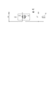
- FIG. 1A is a diagram illustrating a driving circuit for a vibrating body and a vibration type actuator according to an embodiment of the present invention.
- the drive circuit is configured such that the secondary winding coil 105 of the transformer 103 is connected in parallel to the vibrating body 101, and the inductor 102 is connected in series to the transformer primary winding coil 104.
- the inductor 102 an inductance element such as a coil can be used.
- the inductor 102 is generally used for the purpose of removing harmonics and adjusting electric resonance. In the present invention, however, the electric resonance frequency is adjusted and a sufficient driving voltage is considered in consideration of the relationship with the circuit constant of the transformer. Can be ensured, circuit efficiency can be improved, or magnetic noise can be reduced.
- the inductor 102 is connected to the upper side of the transformer primary winding coil 104 in FIG. 1A, it is equivalent to the circuit and may be connected to the lower side.
- the winding ratio of the transformer secondary winding coil 105 to the primary winding coil 104 was set to 16.
- the inductor 1601 is connected to the primary side of the transformer as shown in FIG. It is devised to provide. This is because the coil provided on the primary side is equivalent to the secondary side coil because the impedance is equivalent even if the inductance is reduced to 1 / twice of the turns ratio by the action of the mutual induction of the transformer. This is because characteristics can be obtained.
- the inductor 102 on the primary side of the transformer as in the present invention, one having a small inductance can be used, and the circuit mounting area can be reduced.
- the transformer used in the present invention generally has a transformer coupling coefficient Tk of about 0.95 to 0.98 in order to improve circuit efficiency, reduce magnetic noise, and eliminate harmonics. It is desirable to use one having a high bond. The reason why the coupling coefficient is low is that the leakage magnetic flux from the transformer is large and the efficiency of the transformer itself is lowered. Therefore, the leakage transformer used for preventing excessive voltage causes an increase in magnetic noise and power consumption, and is not suitable for the drive circuit of the present invention.
- FIG. 1B shows an equivalent circuit of the vibrating body 101 of the one-phase portion.
- the equivalent circuit of the vibrating body 101 includes an RLC series circuit of a mechanical vibrating portion and a capacitor 106 having a specific capacitance Cd of the vibrating body 101 connected in parallel to the RLC series circuit.
- the RLC series circuit of the mechanical vibration part can be expressed by using an equivalent coil 107 having a self-inductance Lm, an equivalent capacitor 108 having a capacitance Cm, and an equivalent resistor 109 having a resistance value Rm.
- the constants of the vibration type actuator used in this embodiment are Lm 50 mH, Cm 65 pF, Rm 3 k ⁇ , and Cd 0.54 nF.
- the mechanical resonance frequency of the vibrating body 101 is defined as fm
- fm is 88 kHz.
- FIG. 2 is a diagram for explaining the driving principle of the linear vibration wave driving device according to the present embodiment.
- FIG. 2A an alternating voltage is applied to the piezoelectric element 204 bonded to the elastic body 203 to generate two vibration modes as shown in FIGS.
- the moving body 201 in pressure contact is moved in the direction of the arrow.
- FIG. 2B is a diagram showing an electrode pattern of the piezoelectric element 204.
- the piezoelectric element 204 of the vibrating body 205 is formed with an electrode region divided into two equal parts in the longitudinal direction.
- the polarization direction of the piezoelectric layer corresponding to each electrode region is the same direction (+).
- the alternating voltage (V1) is applied to the electrode region located on the right side in FIG. 2B, and the alternating voltage (V2) is applied to the electrode region located on the left side. .
- V1 and V2 are alternating voltages having a frequency near the resonance frequency of the B mode and whose phase is shifted by 180 °, at a certain moment, the electrode region on the right side of the piezoelectric element 204 contracts and the electrode region on the left side extend.
- the moving body 201 is driven in the direction of the arrow in FIG.
- the generation ratio of the A mode and the B mode can be changed by changing the phase difference of the alternating voltage input to the bisected electrodes.
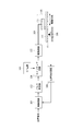
- FIG. 3 is a diagram for explaining a position feedback control system using a drive circuit for a vibration type actuator according to an embodiment of the present invention.
- a position command is given from a controller (not shown) and input to the control circuit 301.
- the deviation is calculated based on the difference between the detection position obtained by the position detection circuit 309 and the position command.
- the control circuit 301 Based on the deviation information, the control circuit 301 performs a calculation by a PID compensator in the control circuit 301 and outputs a control signal as a drive parameter.
- the PID compensator is obtained by adding the outputs of compensators having proportional (P), integral (I), and differential (D) functions, and compensates for the phase delay and gain of the controlled object. It is generally used to construct a stable and highly accurate control system.
- a control signal having frequency, phase difference, and pulse width information that are control parameters of the vibrator is output from the control circuit and input to the pulse generator 302.
- the pulse generator 302 generates a pulse signal whose drive frequency changes according to the input control signal, and a digital frequency divider, a VCO (voltage controlled oscillator), or the like is used. Further, a pulse signal whose pulse width changes according to the control signal may be generated by PWM (pulse width modulation) control.
- the pulse signal output from the pulse generator 302 is input to the switching circuit 304, and a two-phase alternating voltage having a phase difference of 90 ° is output.
- the switching circuit 304 switches the DC voltage supplied from the DC power supply 303 at the timing of the input pulse signal, and generates a rectangular wave alternating voltage.
- the alternating voltage is input to the drive circuit 305 having the configuration shown in FIG. 1A and boosted to a desired drive voltage.
- the alternating voltage of the SIN wave output from the drive circuit 305 is applied to the piezoelectric element 204 through the flexible 306, and the vibrating body 205 and the moving body 201 move relative to each other.
- the relative position of the position scale 307 attached to the moving body 201 is detected by the position sensor 308, and the position information is detected by the position detection circuit 309.
- the position information is input to the control circuit 301, and the vibrator 205 is feedback controlled so as to approach the position command.
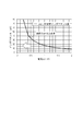
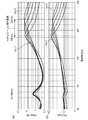
- FIG. 4 is a diagram showing calculation results of power and output voltage of the drive circuit in the embodiment of the present invention. This calculation uses the configuration and circuit constants of the drive circuit shown in FIG. 4A shows the power consumed by the entire circuit, and FIG. 4B shows the output side alternating voltage Vo (voltage applied to the piezoelectric element).
- the power consumption was calculated in consideration of the DC resistance of the coil 0.9 ⁇ , the resistance of the secondary winding coil of the transformer 80 ⁇ , and the equivalent circuit constant of the piezoelectric element.
- the alternating voltage Vi on the input side was set to 6 Vpp so that a step-up ratio of about 16 times was obtained by the transformer.
- the horizontal axis represents the frequency
- the mechanical resonance frequency fm of the vibrating body is 88 kHz, so the driving frequency range was 90 to 100 kHz.
- the vibrator used in the present embodiment can be activated from 100 kHz or less, and starts driving at a low speed at the time of activation. The speed can be increased by sweeping the drive frequency toward the mechanical resonance frequency to the low side. If the mechanical resonance frequency is exceeded, the vibration suddenly stops due to the cliff falling phenomenon of the vibrating body and cannot be driven even if the frequency is increased again. Therefore, a frequency higher than 90 kHz is used for stable driving. Attention is paid to changes in power and drive voltage in this drive frequency range.
- the frequency of the electric resonance peak of the circuit generated by the intrinsic capacitance Cd of the coil, transformer, and piezoelectric element provided on the voltage input side is defined as fe.
- the driving frequency of the vibrator it is possible to drive in a gentle region where the driving voltage changes Rapid change in speed can be suppressed. Therefore, the vibration body can be driven with high accuracy, and a vibration actuator with high performance can be realized.
- the inductance of the coil 102 provided on the voltage input side is defined as Le1
- the inductance of the transformer primary winding coil 104 is defined as L1
- the inductance ratio is defined as Ka below.
- Ka L1 / Le1 (Formula 1-2)
- the Ka is a parameter defined for generalization so as to be able to cope with the difference in mechanical resonance frequency and intrinsic capacitance of the vibrating body. That is, if Ka is set within an appropriate range described in the present invention, an optimum circuit can be configured for driving the vibration type actuator.
- FIG. 15 shows the relationship between the total inductance value of the inductance Le1 and the inductance L1 and the current value flowing through the transformer primary winding coil in the first embodiment.
- the horizontal axis represents the current value on the primary side of the transformer, and the vertical axis represents the total inductance value. If the primary side input voltage is Vin, the voltage on time is Ton, the drive frequency is fd, and the current value is I, the total inductance value is calculated by the following equation.
- the total inductance value and the current have an inverse relationship, it is necessary to increase the total inductance value in order to reduce the current.
- the current value has an upper limit value for preventing the transformer from causing magnetic saturation. Considering the above, the maximum value of the current flowing through the transformer used in the present embodiment is 0.5A. Therefore, from FIG. 15, the total inductance value is required to be 33 ⁇ H or more. On the other hand, if the inductance is increased more than necessary, the wiring resistance of the winding coil increases and the power consumption increases. Therefore, the total inductance value was set to 40 ⁇ H with a margin for 33 ⁇ H. Since Vin, Ton, and I have different conditions depending on the power source and transformer used, the total inductance value may be adjusted based on the above equation.
- FIG. 4 shows a plot of the calculation results when Ka was changed in the range of 0.1 to 10.
- the horizontal axis represents frequency
- (a) shows circuit power consumption
- (b) shows the output side alternating voltage Vo.
- the low frequency side is near 88 kHz, which means that a large current flows through the piezoelectric element near the mechanical resonance frequency.
- the peak frequency changes in the range of 135 to 240 kHz on the high frequency side
- the electrical resonance frequency changes depending on the value of Ka.
- the electrical resonance characteristics of the circuit can be adjusted based on Ka, and the third harmonic can be reduced by shifting the electrical resonance frequency to the low frequency side.
- the drive frequency is 100 kHz
- the power consumption and drive voltage of the circuit change depending on the value of Ka. That is, by optimizing Ka, it is possible to configure a circuit that outputs a sufficient alternating voltage while reducing the power consumption of the circuit.
- Ka the characteristics of the electrical resonance frequency fe and the alternating voltage
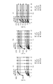
- FIG. 18 shows the calculation result of the electrical resonance frequency fe based on Ka in the embodiment of the present invention. Since fe can be adjusted to the low frequency side by changing Ka, the third-order harmonic can be reduced for the reasons described later, and the circuit efficiency can be improved.
- the value of the inductance L1 of the transformer primary winding coil 104 was compared under each condition of 1 ⁇ H, 10 ⁇ H, 30 ⁇ H, and 100 ⁇ H. 1 ⁇ H may be considered as the minimum value that can be realized as a winding coil of a transformer.
- FIG. 18 (a) shows the result when Ka is swung from 0.2 to 30 under the condition that the turns ratio is 16 times and Cd is 0.47 nF.
- Ka ⁇ 10 the value of the electrical resonance frequency fe is small. Therefore, by setting Ka ⁇ 10, fe can be effectively shifted to the low frequency side. That is, the ratio of the third harmonic to the fundamental wave can be reduced. This tendency was found to be the same even when the value of L1 was changed.
- FIG. 18 (b) shows the result under the condition that the winding ratio is 10 times and Cd is 0.47nF
- FIG. 18 (c) shows the result under the condition that the winding ratio is 10 times and Cd is 3.5nF. From these results, it has been found that even if the turns ratio of the transformer and the intrinsic capacitance of the piezoelectric element are changed, fe can be adjusted to the low frequency side with a smaller inductance if Ka ⁇ 10.
- the value of Ka that can reduce the ratio of the third harmonic to the fundamental wave by adjusting fe to the low frequency side is set to an appropriate range, Ka ⁇ 10 (Formula 1-4) I derived that. If the value of Ka is appropriate, the circuit power consumption of the vibration type actuator can be reduced.
- the resonance frequency and the capacitance of the piezoelectric element are different. Therefore, it is necessary to change the circuit constant for each vibrator. Furthermore, even if the same vibrating body is used, if there are multiple vibrating bodies to be driven, if the drive circuit is shared, the capacitance increases with the number, so the electrical resonance characteristics of the circuit will vibrate. It is different from the case of a single body. Further, when designing a drive circuit corresponding to a plurality of vibrators, there are many design parameters such as inductance values of each element of the drive circuit, and there are innumerable combinations as long as a necessary drive voltage is simply output. The combination of these circuit constants is mainly left to the judgment of the designer, but the result greatly affects the power consumption and controllability when driving the vibrator.
- the drive circuit of the present invention is a drive circuit with good circuit efficiency and reduced power consumption regardless of the structure and size of the vibrating body, the vibration mode and the number.
- the drive circuit of the present invention is, for example, a transformer booster circuit.
- the drive circuit is designed to satisfy Ka ⁇ 10 by paying attention to the relationship between coils and transformer constants, the number of multiple vibrators, and the inductance value of the transformer. By doing so, a drive circuit with good circuit efficiency can be designed.
- the transformer when the current flowing through the coil on the primary side of the transformer exceeds the maximum allowable input current value Imax, the transformer is in a magnetic saturation state, and boosting cannot be performed appropriately.
- the primary-side input voltage Vin and the voltage on-time Ton can be taken according to the power source connected to the input side and the frequency and amplitude required for the alternating voltage for driving the vibrating body under desired conditions, respectively. The value is determined and the degree of freedom in design is not large.
- the input current value I is determined by the input voltage Vin on the primary side, the voltage on time Ton, and the total inductance value of the inductance Le1 and the inductance L1.
- FIG. 19 shows the calculation result of the voltage ratio based on Ka in the embodiment of the present invention.
- the voltage ratio in FIG. 19 is normalized by Vo / Vin / R, and is obtained by dividing the input / output voltage ratio by the turn ratio R.
- the value of the inductance L1 of the transformer primary winding coil 104 was confirmed under the conditions of 1 ⁇ H, 10 ⁇ H, 30 ⁇ H, and 100 ⁇ H, as in FIG. 18, but there was no difference depending on the conditions. Only the results were plotted.
- the ideal voltage ratio is 1, a certain decrease is inevitable due to a trade-off with the effect of adjusting fe to the low frequency side. Therefore, considering the adjustment of fe to the low frequency side, a configuration in which the voltage ratio is 0.5 or more is considered preferable.
- FIG. 19 (a) shows the results when Ka was swung from 0.2 to 30 under the condition that the winding ratio was 16 times and Cd was 0.47 nF. As shown in the figure, it was found that if Ka ⁇ 1, the voltage ratio is 0.5 or more.
- FIG. 19 (b) shows the result under the condition where the turn ratio is 10 times and Cd is 0.47nF
- FIG. 19 (c) shows the result under the condition where the turn ratio is 10 times and Cd is 3.5nF. From these results, even when the turns ratio of the transformer and the intrinsic capacitance of the piezoelectric element change, the relationship between the voltage ratio and Ka shows the same tendency, and if Ka ⁇ 1, it is more than half of the transformer turns ratio. It was found that a voltage (voltage ratio of 0.5 or more) was obtained.
- the value of Ka for obtaining a drive voltage that is more than half of the turns ratio is: 1 ⁇ Ka (Formula 1-6) I derived that. Therefore, if the value of Ka is 1 ⁇ Ka ⁇ 10, it is possible to obtain a good driving voltage while reducing the circuit power consumption of the vibration type actuator. Furthermore, since a transformer having a smaller inductance can be designed, a circuit element that can be easily manufactured can be designed. Since the outer size of the transformer and coil is determined by the turn ratio and inductance value, it is necessary to reduce these values in order to reduce the circuit mounting area. In addition, since the harmonic current can be reduced, magnetic noise from the transformer can also be reduced.
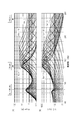
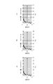
- FIG. 5 is a diagram showing the relationship between the inductances of the coil based on Ka and the transformer primary winding coil, and the calculation result of the alternating voltage and power consumption at 100 kHz in the embodiment of the present invention.
- FIG. 5A shows the relationship between the inductances (Le1, L1) of the coil 102 and the transformer primary winding coil 104 based on Ka. The total value of Le1 and L1 is 40 ⁇ H, and Ka is changed from 0 to 10.
- the relationship between the inductances (Le1, L1) of the coil 102 and the transformer primary winding coil 104 is more preferably 1.5 ⁇ Ka ⁇ 3.0.
- FIG. 5 (b) shows the result of the ratio of the voltage of the third harmonic based on Ka to the fundamental wave.
- the third harmonic is the numerator and the fundamental wave is the denominator.
- the voltage of the third harmonic is a voltage value at 300 kHz that is three times the driving frequency is 100 kHz.
- the alternating voltage Vi input to the primary side of the transformer is a rectangular wave as described above, and the harmonic component contained in the rectangular wave has the largest third harmonic, followed by the fifth and seventh. That is, if the ratio of the third harmonic is large, a SIN wave having a large waveform distortion is generated, and an unnecessary current flows, leading to a reduction in efficiency and generation of magnetic noise.
- Ka the electrical resonance frequency fe of the circuit shifts to the high frequency side, so that the ratio of the third harmonic increases.
- Ka ⁇ 5 the fundamental wave voltage is the third harmonic voltage in all cases where the value of Le1 + L1 is 20 ⁇ H, 40 ⁇ H, and 60 ⁇ H. It becomes a larger value. Therefore, from the viewpoint of reducing the influence of harmonics, Ka preferably satisfies Ka ⁇ 5.
- the inductance L1 of the primary winding coil is set as shown in FIG. A graph may be created and determined. That is, assuming that the voltage amplitude with the drive frequency as the fundamental wave is V1, and the voltage amplitude of the third harmonic is V3, the primary winding coil 104 and the coil 102 have a ratio V3 / V1 of the third harmonic of the alternating voltage.
- the inductance value is preferably 0.5 or less.
- FIG. 5C shows the result of circuit power consumption based on Ka.
- the power consumption tends to increase as the drive voltage increases.
- the total value of Le1 and L1 may be 60 ⁇ H.
- the power consumption can be further reduced by setting the total value to 40 ⁇ H. If the inductance is reduced, a smaller transformer can be used, and the circuit mounting area can be reduced.
- the electrical resonance frequency fe and the mechanical resonance frequency fm of the vibrating body satisfy the following (Equation 1-7). 1.30 ⁇ fm ⁇ fe ⁇ 2.50 ⁇ fm (Formula 1-7)
- the voltage ratio of the third harmonic to the fundamental wave is 1.0 or less.
- the capacitance Cd of the piezoelectric element and the turns ratio of the transformer may be adjusted.
- the input current is increased, so that the power consumption is increased.
- the turn ratio the input voltage of the drive circuit must be changed, which is difficult due to restrictions on the power supply used. Therefore, by setting the electric resonance frequency fe and the mechanical resonance frequency fm of the vibrating body to a value satisfying the above (Equation 1-7), a sufficient boosting effect can be obtained and harmonics can be reduced.
- the driving circuit of the vibrator by determining the total value of Le1 and L1 and the ratio Ka so that (Equation 1-7) is satisfied, sufficient boosting effect and harmonics can be obtained. Can be reduced.
- FIG. 5D shows the result of the alternating voltage Vo based on Ka.
- the total values of Le1 and L1 are plotted together for cases of 20 ⁇ H, 40 ⁇ H, and 60 ⁇ H.
- Le1 + L1 is 20 ⁇ H and 40 ⁇ H
- fe was 135 to 180 kHz (1.53 to 2.05 times fm) in the range of 1 ⁇ Ka ⁇ 10. This is a case where the total value of Le1 and L1 is 40 ⁇ H.
- FIG. 6 is a diagram showing a calculation result of the circuit power consumption and the alternating voltage Vo when the total value of Le1 and L1 is 60 ⁇ H.
- FIG. 6A shows the circuit power consumption
- FIG. 21 is a diagram showing a calculation result of the circuit power consumption and the alternating voltage Vo when the total value of Le1 and L1 is 20 ⁇ H.
- FIG. 21A shows circuit power consumption
- fe is 188 to 220 kHz (2.14 to 2.50 times fm).
- the electric resonance frequency fe uses both series electric resonance by Le1 and capacitance Cd, and parallel electric resonance by L1 and capacitance Cd. The smaller the inductance, the shorter the response period, and the larger the resonance frequency. "" Therefore, when other conditions are constant, the electrical resonance frequency fe increases as the total value of Le1 and L1 decreases.
- the total value of Le1 and L1 is included in the range from 20 ⁇ H to 60 ⁇ H.
- the appropriate range of fe can be expressed by the above (Formula 1-7).
- the resonance of the vibrator having the electro-mechanical energy conversion element is fe
- the resonance of the vibrator having the electro-mechanical energy conversion element is 1.30 ⁇ fm ⁇
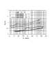
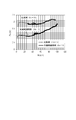
- FIG. 7 is a diagram showing experimental results of power consumption of the entire circuit in the drive circuit of the present embodiment.
- the horizontal axis represents the speed at which the vibrator is driven, and the vertical axis represents the power consumption.
- a comparative example is plotted.
- the inductance of the coil that is the inductor 102 is Le1
- the inductance of the transformer primary winding coil is L1
- the inductance of the transformer primary winding coil 104 is L2.
- the power supply voltage is adjusted in the range of 2.75 V to 3.5 so that the drive voltage output from the circuit is about 120 Vpp.
- the voltage is sufficiently ensured, but since Ka is large, the harmonic component is large and the efficiency is reduced.
- the value of power consumption is approximately 1.0 W or less, and both suppress harmonics compared to the comparative example, and the power consumption is reduced. Since the application example 3 of the present invention has a smaller harmonic ratio than the application example 1, the power consumption can be further suppressed.
- the application example 3 of the present invention can suppress the decrease in the driving voltage as compared with the application example 2, the power input from the power source to obtain the necessary driving force can be suppressed, so that the power consumption is reduced. Therefore, the application example 3 of the present invention is the most efficient result.
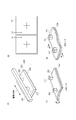
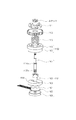
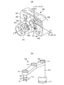
- FIG. 11 is an exploded perspective view of a rod-shaped vibrator that can be used for zoom driving and autofocus driving of a camera lens.
- the vibrator includes a vibrating body 1101 and a moving body 1102.
- the vibrating body 1101 includes a first elastic body 1103 including a friction portion made of a friction material, a piezoelectric element 1104 that is an electro-mechanical energy conversion element, a flexible printed board 1105 for supplying power to the piezoelectric element 1104, and a second elastic body. 1106.
- the first elastic body 1103 is, for example, a sintered ceramic whose main component is alumina, and the upper friction surface side is finished and polished after both upper and lower surfaces are ground.
- the moving body 1102 includes a contact spring 1109 and a rotor 1110. The contact spring 1109 is bonded and fixed to the rotor 1110, for example.
- the moving body 1102 is in pressure contact with the friction surface 1114 of the vibrating body 1101 by the output gear 1112 rotatably supported by the bearing portion of the flange 1111 and the pressure spring 1113.
- the contact spring 1109 of the moving body 1102 is formed in a cylindrical shape having a small crank cross section by drawing stainless steel, and the lower end surface is in contact with the friction surface 1114 of the first elastic body of the vibrating body as a friction surface of the moving body. ing.
- An alternating signal is applied to the piezoelectric element 1104 from a power source (not shown) via the flexible printed circuit board 1105.
- the mechanical resonance frequency fm of the vibrating body 1101 is 42 kHz, and the intrinsic capacitance Cd is 9 nF.
- the power supply voltage was set to 5 V
- the turns ratio of the transformer was set to 8 times
- the required drive voltage of 70 to 110 Vpp was obtained in the drive frequency range of 42.5 to 44 kHz.
- the inductance of the coil is Le1
- the inductance of the transformer primary winding coil is L1
- the inductance of the transformer primary winding coil is L2.
- Ka 1.8.
- the circuit to which the present invention is applied has a drive voltage of 1.3 times and power consumption can be reduced by half.
- the drive circuit according to the present embodiment can also be applied to vibration type actuators having different resonance frequencies fm and specific capacitances Cd of piezoelectric elements.
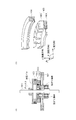
- FIG. 14 is a schematic diagram showing a configuration of a traveling wave type vibrator. First, an outline of the vibrator in the present embodiment will be described.
- FIG. 14A is a schematic diagram showing a cross section of a traveling wave type vibrator.
- the vibrator is connected to the common housing 1401 via one output shaft 1402.
- a two-phase alternating voltage output from a drive circuit (not shown) to a drive electrode provided on the piezoelectric element 1404 of the vibrating body 1403, the moving body 1406 is rotationally driven in the same direction.
- FIG. 14B is a perspective view showing a part of the vibrator.
- the vibrator includes a piezoelectric element 1404 that is an electro-mechanical energy conversion element, a vibrating body 1403 having an elastic body 1405, and a moving body 1406. Each member has an annular shape in the ⁇ direction in the figure.
- a traveling wave is generated in the vibrating body 1403, and the moving body 1406 in contact with the vibrating body 1403 rotates relative to the vibrating body by friction driving.
- the mechanical resonance frequency fm of the vibrating body 1403 is 44 kHz, and the intrinsic capacitance Cd is 3.5 nF.
- the power supply voltage is 24 V
- the transformer turns ratio is set to 10 times
- the drive voltage is designed to obtain a drive voltage of 500 Vpp in the drive frequency range of 45 to 50 kHz.
- the inductance of the coil is Le1
- the inductance of the transformer primary winding coil is L1
- the inductance of the transformer primary winding coil is L2.
- L1 15 ⁇ H
- L2 1.50 mH
- a coil with Le1 10 ⁇ H
- the application example of the driving circuit for the vibrating body of the present invention is not limited to the above.
- the vibrating body is a dust removing device, that is, the driving circuit of the dust removing device can be used.
- FIG. 16 shows the configuration of the drive circuit of the second embodiment.
- a coil is provided as an inductor 1601 on the secondary side of the transformer.
- the inductance is defined as Le2
- the inductance of the transformer secondary winding coil is defined as L2
- the inductance ratio is defined as Kb.
- Kb L2 / Le2 (Formula 2-1)
- the input voltage Vi on the transformer primary side, the turns ratio of the transformer to be used and the upper limit value of the current, various constants such as the mechanical resonance frequency of the vibrator, and the necessary drive voltage are the same as those in the first embodiment. It is.
- the inductance L1 of the transformer primary winding coil is set to 40 ⁇ H. Therefore, when the transformer turns ratio is R, the inductance value L2 of the transformer secondary winding coil is 10.24 mH from the following equation.
- L2 L1 ⁇ R 2 (Formula 2-2)
- FIG. 17 shows the calculation result of the electric resonance frequency fe and the voltage ratio based on Kb in the embodiment of the present invention.
- fe can be adjusted to the low frequency region side in accordance with Kb, so that the third harmonic can be reduced and the circuit efficiency can be improved.
- the value of the inductance L2 of the transformer secondary winding coil 105 was compared under the conditions of 0.256 mH, 2.56 mH, 7.68 mH, and 25.6 mH. Since the turn ratio is 16 times, in the case of 0.256 mH, the primary winding coil of the transformer corresponds to a minimum value of 1 ⁇ H that can be realized.
- FIG. 17 (a) shows the calculation result of fe when Kb is swung from 0.2 to 30 under the condition that the turns ratio is 16 times and Cd is 0.47 nF.
- Kb ⁇ 10 fe can be effectively shifted to the low frequency side. That is, the ratio of the third harmonic to the fundamental wave can be reduced. This tendency was found to be the same even when the value of L2 was changed.
- Ka even if the turns ratio of the transformer and the intrinsic capacitance of the piezoelectric element change, if Kb ⁇ 10, fe can be adjusted to the low frequency side.
- Kb satisfies the following (Equation (2-3)) Is preferred. Kb ⁇ 10 (Formula 2-3)
- FIG. 17B shows the calculation result of the voltage ratio based on Kb.
- the voltage ratio is normalized by Vo / Vin / R, and the input / output voltage ratio is divided by the turn ratio R.
- the voltage ratio was 0.5 or more in the entire range of Kb. That is, the output voltage is hardly affected by the inductance Le2 of the inductor provided on the secondary side of the transformer.
- Ka was affected. The reason for this depends on the difference in voltage supplied to the primary winding coil 104 of the transformer. In the case of Ka, the input voltage is divided into the coil 102 and the primary winding coil 104.
- FIG. 12 shows the ratio of the voltage amplitude to the fundamental wave of the third harmonic based on Kb.
- L2 is 5.12 mH, 7.68 mH, 10.24 mH
- the third harmonic is the numerator and the fundamental wave is the denominator.
- the voltage of the third harmonic is a value at 300 kHz that is three times the driving frequency is 100 kHz.
- the alternating voltage Vi input to the primary side of the transformer is a rectangular wave as described above, and the harmonic component contained in the rectangular wave has the largest third harmonic.
- the condition that the ratio of the third harmonic is 0.5 or less is that when L2 is 5.12 mH, the value of Kb satisfies Kb ⁇ about 5, and when L2 is 10.24 mH, Kb Is when Kb ⁇ about 10.
- FIG. 13 is a diagram showing calculation results of the circuit power consumption and the alternating voltage Vo in the second embodiment.
- the transformer constants are 40 ⁇ H for L1 and 10.24 mH for L2, and show the calculation results in the range of 1 ⁇ Kb ⁇ 5.
- the horizontal axis represents frequency
- FIG. 13A shows the power consumed by the entire circuit
- FIG. 13B shows the output side alternating voltage Vo.
- FIG. 13B shows that the electrical resonance frequency fe of the circuit shifts to the high frequency side as Kb increases.
- the electric resonance frequency fe is close to the upper limit of 100 kHz of the driving frequency
- the resistance is changed to the transformer primary so that excessive voltage is not applied to the vibrating body. It may be designed to reduce the peak voltage by providing it on the side or secondary side.
- the electric resonance frequency fe is 115 to 135 kHz (1.30 to 1.53 times fm). In this case, from the result of FIG.
- FIG. 8 shows an example of a vibration type actuator composed of a plurality of vibration bodies in the embodiment of the present invention.
- driving is performed using a driving circuit in which three vibrating bodies are connected in parallel on the secondary side of the transformer.
- FIG. 8A is a diagram showing a configuration of a vibration type actuator using three vibration bodies of the present embodiment.
- Reference numeral 801 denotes a base plate serving as a base of the vibration type actuator, and reference numerals 803, 804, and 805 denote vibration bodies that drive the movable body 802 to rotate.
- the vibrating body is the same as that of the first embodiment, and the output terminals of the driving circuit are connected in parallel to the three vibrating bodies, and two-phase driving signals are respectively supplied via the flexible cable 809. Then, the three vibrators are driven by the common drive circuit 810.
- a driving voltage is applied, a vibration wave that generates a driving force is generated in each vibrating body, and the moving body 802 is driven to rotate about the rotation shaft 807 by the resultant force of the driving forces of the vibrating bodies 803, 804, and 805. Is done.
- the combined rotational driving force acts on the moving body 802, so that the torque can be increased up to three times.
- a position sensor 806 detects the rotational position of the moving body 802.
- Fig. 8 (b) is a side view of the apparatus.
- the vibrating bodies 803, 804, and 805 are formed by integrating a vibrating member having a two-point protrusion and a piezoelectric element (not shown) by bonding or the like, and are attached to the base plate 801 via an attaching member.
- a disk-shaped scale portion 808 is provided on the upper surface of the position sensor 806. As the scale unit 808 moves in the rotation direction, a position signal corresponding to the amount of movement is output from the position sensor 806.
- FIG. 9 is a diagram showing a driving circuit for one phase of a vibrating body in a vibration type actuator including a plurality of vibrating bodies according to the present embodiment.
- the drive circuit is configured such that an inductor 904 is connected in series to a transformer primary winding coil 906, and vibrators 901, 902, and 903 are connected in parallel to a secondary winding coil 907 of the transformer 905.
- an inductance element such as a coil can be used as the inductor 904
- the inductor 904 is connected to the upper side of the transformer primary winding coil 906 in FIG. 9A, it may be connected to the lower side because it is equivalent in circuit.
- the winding ratio of the transformer secondary winding coil 907 to the primary winding coil 906 was set to 20.
- FIG. 9B shows the one-phase vibrating body 901 as an equivalent circuit.
- the equivalent circuit of the vibrating body 901 includes an RLC series circuit of a mechanical vibrating portion and a capacitor 908 having a specific capacitance Cd of the vibrating body 901 connected in parallel to the RLC series circuit.
- the RLC series circuit of the mechanical vibration part can be expressed using an equivalent coil 909 having a self-inductance Lm, an equivalent capacitor 910 having a capacitance Cm, and an equivalent resistor 911 having a resistance value Rm.
- Lm was 50 mH
- Cm was 65 pF
- Rm was 3 k ⁇
- Cd 0.54 nF.
- the vibrating bodies 902 and 903 are also represented by a similar equivalent circuit. Accordingly, the specific capacitance of the three vibrators is 1.62 nF, which is three times.
- a plurality of vibrating bodies are connected in parallel to the secondary winding of the transformer, and when driving a plurality of vibrating bodies by using a common transformer, the inductance of the transformer is set as follows: When set, matching can be achieved electrically.
- the transformer turns ratio is R
- the transformer primary winding coil is Ln1
- the secondary winding coil inductance Ln2 and the primary coil is Let Len1.
- Len1 Ln1 / Ka (Formula 3-1) And set.
- the inductance Ln1 of the transformer primary winding coil is 6.25 ⁇ H.
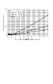
- FIG. 10 is a diagram showing experimental results of power consumption of the entire circuit in the drive circuit of this embodiment.
- the horizontal axis represents the speed when the ultrasonic motor is driven, and the vertical axis represents the power consumption.
- a comparative example is plotted.
- the inductance of the coil that is the inductor 904 is Len1
- the inductance of the transformer primary winding coil 906 is Ln1
- the inductance of the transformer secondary winding coil 907 is Ln2.
- the winding resistance is set by matching the inductance of the transformer with a plurality of vibrating bodies after setting Ka to an optimal value and realizing sufficient drive voltage and harmonic suppression.
- FIG. 20A is a perspective view showing a schematic structure of a digital camera 400 which is an example of an imaging apparatus, and shows a part thereof in a transparent state.
- a lens barrel 410 is attached to the front surface of the digital camera 400, and a plurality of lenses (not shown) including a focus lens 407 and a camera shake correction optical system 403 are disposed inside the lens barrel 410. Yes.
- the image stabilization optical system 403 can vibrate in the vertical direction (Y direction) and the horizontal direction (X direction) by transmitting the rotation of the biaxial coreless motors 404 and 405.
- a microcomputer (MPU) 409 that controls the overall operation of the digital camera 400 and an image sensor 408 are arranged.
- the image sensor 408 is a photoelectric conversion device such as a CMOS sensor or a CCD sensor, and converts an optical image formed by the light passing through the lens barrel 410 into an analog electric signal. Therefore, the image sensor 408 is disposed on the optical axis of the focus lens 407.
- An analog electrical signal output from the image sensor 408 is converted into a digital signal by an A / D converter (not shown), and then subjected to predetermined image processing by an image processing circuit (not shown) to obtain image data (video data). It is stored in a storage medium such as a semiconductor memory (not shown).
- a gyro sensor 401 that detects the amount of shake (vibration) in the vertical direction (pitching) and a gyro sensor that detects the amount of shake (vibration) in the left-right direction (yawing). 402 is arranged.
- Coreless motors 404 and 405 are driven in the direction opposite to the vibration detected by the gyro sensors 401 and 402 to vibrate the optical axis of the camera shake correction optical system 403. As a result, the vibration of the optical axis due to camera shake is canceled out, and a good photograph in which camera shake is corrected can be taken.
- the vibrating body is used as a drive unit 300 that drives the focus lens 407 disposed in the lens barrel 410 via a gear train (not shown) in the optical axis direction.
- the present invention is not limited to this, and the vibrating body may be used for driving an arbitrary lens such as a zoom lens (not shown) or for driving an image sensor at the time of camera shake correction instead of the coreless motors 404 and 405. it can.
- the driving circuit for the vibrator according to each embodiment described above may be applied to an industrial robot.
- FIG. 20B is a perspective view showing a schematic structure of the robot 100 on which the vibration type driving device is mounted.
- a horizontal articulated robot which is a kind of industrial robot is illustrated.
- the vibrating body is built in the arm joint portion 111 and the hand portion 112 in the robot 100.
- the arm joint unit 111 connects the two arms so that the angle at which the two arms 120 intersect can be changed.
- the hand unit 112 includes an arm 120, a grip part 121 attached to one end of the arm 120, and a hand joint part 122 that connects the arm 120 and the grip part 121.
- the vibrating body is used for the arm joint part 111 that changes the angle between the arms 120 and the hand joint part 122 that rotates the grip part 121 by a predetermined angle.
- the driving circuit for the vibrator according to each embodiment described above can be provided in the image forming apparatus or the dust removing apparatus described above.
- the driving circuit for the vibrator can be used, for example, for driving a rotating drum.
- the vibrator driving circuit is provided with the vibrator on the substrate, and the vibrator is driven by the driving circuit to vibrate the substrate to remove dust on the substrate. Can do.
- This dust removing device can be provided, for example, on the optical axis of the lens of the imaging device.
- low power consumption can be realized in the imaging device, the robot, the dust removing device, or the image forming device.
Landscapes
- Physics & Mathematics (AREA)
- General Physics & Mathematics (AREA)
- Optics & Photonics (AREA)
- Engineering & Computer Science (AREA)
- Multimedia (AREA)
- Signal Processing (AREA)
- General Electrical Machinery Utilizing Piezoelectricity, Electrostriction Or Magnetostriction (AREA)
- Apparatuses For Generation Of Mechanical Vibrations (AREA)
- Lens Barrels (AREA)
- Adjustment Of Camera Lenses (AREA)
Priority Applications (2)
| Application Number | Priority Date | Filing Date | Title |
|---|---|---|---|
| CN201480074777.0A CN105981288B (zh) | 2013-12-26 | 2014-12-22 | 振动元件驱动电路、振动型致动器、图像拾取装置、图像生成装置以及除尘装置 |
| US15/108,250 US10270371B2 (en) | 2013-12-26 | 2014-12-22 | Vibrating-element driving circuit, vibration-type actuator, image pickup apparatus, image generation apparatus, and dust removal apparatus |
Applications Claiming Priority (4)
| Application Number | Priority Date | Filing Date | Title |
|---|---|---|---|
| JP2013-269678 | 2013-12-26 | ||
| JP2013269678 | 2013-12-26 | ||
| JP2014-256709 | 2014-12-18 | ||
| JP2014256709A JP6415301B2 (ja) | 2013-12-26 | 2014-12-18 | 振動体の駆動回路、振動型アクチュエータ、撮像装置、画像生成装置、及び塵埃除去装置 |
Publications (1)
| Publication Number | Publication Date |
|---|---|
| WO2015098800A1 true WO2015098800A1 (ja) | 2015-07-02 |
Family
ID=53478654
Family Applications (1)
| Application Number | Title | Priority Date | Filing Date |
|---|---|---|---|
| PCT/JP2014/083841 Ceased WO2015098800A1 (ja) | 2013-12-26 | 2014-12-22 | 振動体の駆動回路、振動型アクチュエータ、撮像装置、画像生成装置、及び塵埃除去装置 |
Country Status (4)
| Country | Link |
|---|---|
| US (1) | US10270371B2 (https=) |
| JP (1) | JP6415301B2 (https=) |
| CN (1) | CN105981288B (https=) |
| WO (1) | WO2015098800A1 (https=) |
Cited By (2)
| Publication number | Priority date | Publication date | Assignee | Title |
|---|---|---|---|---|
| WO2015174039A1 (en) * | 2014-05-14 | 2015-11-19 | Canon Kabushiki Kaisha | Vibration type driving apparatus, interchangeable lens and imaging apparatus including vibration type driving apparatus, and method for adjusting vibration type driving apparatus |
| US10439518B2 (en) | 2015-09-30 | 2019-10-08 | Canon Kabushiki Kaisha | Vibration-type actuator, driving method for vibration-type actuator, and electronic apparatus equipped with vibration-type actuator |
Families Citing this family (11)
| Publication number | Priority date | Publication date | Assignee | Title |
|---|---|---|---|---|
| JP6866128B2 (ja) * | 2015-12-04 | 2021-04-28 | キヤノン株式会社 | 振動型アクチュエータの駆動方法、振動型駆動装置及び機械装置 |
| JP2018143961A (ja) * | 2017-03-06 | 2018-09-20 | ローム株式会社 | 振動モータの駆動回路、そのキャリブレーション方法、振動装置および電子機器 |
| KR101899538B1 (ko) * | 2017-11-13 | 2018-09-19 | 주식회사 씨케이머티리얼즈랩 | 햅틱 제어 신호 제공 장치 및 방법 |
| US10637375B2 (en) * | 2017-12-15 | 2020-04-28 | Samsung Electro-Mechanics Co., Ltd. | Actuator and position control apparatus using voice coil motor method with temperature compensation function |
| JP7191547B2 (ja) * | 2018-05-11 | 2022-12-19 | キヤノン株式会社 | 振動型駆動装置、電子機器及び振動型アクチュエータの制御方法 |
| JP7265826B2 (ja) * | 2019-01-23 | 2023-04-27 | キヤノン株式会社 | 駆動装置、像振れ補正装置及び像振れ補正装置を備えた撮像装置 |
| JP7297489B2 (ja) * | 2019-03-26 | 2023-06-26 | キヤノン株式会社 | 振動型アクチュエータおよび振動型アクチュエータの駆動装置 |
| JP2020182329A (ja) * | 2019-04-25 | 2020-11-05 | キヤノン株式会社 | 振動型アクチュエータおよび振動型アクチュエータの駆動装置 |
| JP7286453B2 (ja) * | 2019-07-18 | 2023-06-05 | キヤノン株式会社 | 制御装置、振動型アクチュエータ、撮像装置、および制御方法 |
| US20240272451A1 (en) * | 2021-06-15 | 2024-08-15 | Acuvi Ab | Optical System and Method for Image Stabilization of such an Optical System |
| WO2023229308A1 (en) * | 2022-05-23 | 2023-11-30 | Kt & G Corporation | Aerosol generating device with full bridge driving circuit |
Citations (4)
| Publication number | Priority date | Publication date | Assignee | Title |
|---|---|---|---|---|
| JPH0442788A (ja) * | 1990-06-07 | 1992-02-13 | Sony Corp | 超音波モータの駆動回路 |
| JP2002101673A (ja) * | 2000-09-20 | 2002-04-05 | Nippon Soken Inc | ピエゾアクチュエータ駆動回路 |
| JP2011109882A (ja) * | 2009-11-20 | 2011-06-02 | Canon Inc | 振動型アクチュエータの駆動回路 |
| JP2013247800A (ja) * | 2012-05-28 | 2013-12-09 | Nikon Corp | 振動波モータの駆動装置、レンズ鏡筒及びカメラ |
Family Cites Families (10)
| Publication number | Priority date | Publication date | Assignee | Title |
|---|---|---|---|---|
| JP2622128B2 (ja) | 1987-10-20 | 1997-06-18 | キヤノン株式会社 | 振動波モーター装置 |
| JP2618685B2 (ja) | 1988-05-19 | 1997-06-11 | ティーディーケイ株式会社 | 圧電振動子駆動回路 |
| JPH04222477A (ja) | 1990-12-26 | 1992-08-12 | Kubota Corp | 超音波モータの電源回路 |
| JP3165701B2 (ja) | 1991-03-06 | 2001-05-14 | キヤノン株式会社 | 振動波モーター |
| JPH05111267A (ja) | 1991-10-11 | 1993-04-30 | Asmo Co Ltd | 超音波モータの駆動回路 |
| US5777444A (en) | 1995-12-27 | 1998-07-07 | Nikon Corporation | Drive device for a vibration actuator which prevents the cogging phenomenon |
| JP2001136764A (ja) | 1999-11-04 | 2001-05-18 | Mitsuba Corp | 超音波モータ用制御回路 |
| CN101686022B (zh) | 2008-09-24 | 2012-03-28 | 无锡华润矽科微电子有限公司 | 一种超声电机驱动电路 |
| JP5693262B2 (ja) * | 2011-01-28 | 2015-04-01 | キヤノン株式会社 | 振動体の駆動回路 |
| JP6579778B2 (ja) * | 2014-05-14 | 2019-09-25 | キヤノン株式会社 | 振動型駆動装置、振動型駆動装置を備える交換用レンズ、撮像装置、及び振動型駆動装置の製造方法 |
-
2014
- 2014-12-18 JP JP2014256709A patent/JP6415301B2/ja active Active
- 2014-12-22 US US15/108,250 patent/US10270371B2/en active Active
- 2014-12-22 WO PCT/JP2014/083841 patent/WO2015098800A1/ja not_active Ceased
- 2014-12-22 CN CN201480074777.0A patent/CN105981288B/zh active Active
Patent Citations (4)
| Publication number | Priority date | Publication date | Assignee | Title |
|---|---|---|---|---|
| JPH0442788A (ja) * | 1990-06-07 | 1992-02-13 | Sony Corp | 超音波モータの駆動回路 |
| JP2002101673A (ja) * | 2000-09-20 | 2002-04-05 | Nippon Soken Inc | ピエゾアクチュエータ駆動回路 |
| JP2011109882A (ja) * | 2009-11-20 | 2011-06-02 | Canon Inc | 振動型アクチュエータの駆動回路 |
| JP2013247800A (ja) * | 2012-05-28 | 2013-12-09 | Nikon Corp | 振動波モータの駆動装置、レンズ鏡筒及びカメラ |
Cited By (3)
| Publication number | Priority date | Publication date | Assignee | Title |
|---|---|---|---|---|
| WO2015174039A1 (en) * | 2014-05-14 | 2015-11-19 | Canon Kabushiki Kaisha | Vibration type driving apparatus, interchangeable lens and imaging apparatus including vibration type driving apparatus, and method for adjusting vibration type driving apparatus |
| US10031316B2 (en) | 2014-05-14 | 2018-07-24 | Canon Kabushiki Kaisha | Vibration type driving apparatus, interchangeable lens and imaging apparatus including vibration type driving apparatus, and method for adjusting vibration type driving apparatus |
| US10439518B2 (en) | 2015-09-30 | 2019-10-08 | Canon Kabushiki Kaisha | Vibration-type actuator, driving method for vibration-type actuator, and electronic apparatus equipped with vibration-type actuator |
Also Published As
| Publication number | Publication date |
|---|---|
| JP6415301B2 (ja) | 2018-10-31 |
| US20160329836A1 (en) | 2016-11-10 |
| JP2015144556A (ja) | 2015-08-06 |
| CN105981288B (zh) | 2018-05-04 |
| CN105981288A (zh) | 2016-09-28 |
| US10270371B2 (en) | 2019-04-23 |
Similar Documents
| Publication | Publication Date | Title |
|---|---|---|
| JP6415301B2 (ja) | 振動体の駆動回路、振動型アクチュエータ、撮像装置、画像生成装置、及び塵埃除去装置 | |
| JP6579778B2 (ja) | 振動型駆動装置、振動型駆動装置を備える交換用レンズ、撮像装置、及び振動型駆動装置の製造方法 | |
| JP6639148B2 (ja) | 振動型アクチュエータの駆動回路、振動装置、交換用レンズ、撮像装置、及び自動ステージ | |
| CN102759842B (zh) | 用于振动装置的驱动电路 | |
| US8791622B2 (en) | Driving circuit for vibration-type actuator | |
| KR20180061309A (ko) | 고전압 용량성 액추에이터용 드라이버 | |
| JP5693262B2 (ja) | 振動体の駆動回路 | |
| JP5364466B2 (ja) | 超音波モータの駆動回路装置 | |
| JP2017028933A (ja) | 制御装置、振動型駆動装置、塵埃除去装置、レンズ鏡筒及び撮像装置 | |
| JP6671883B2 (ja) | 振動型アクチュエータの制御装置とその制御方法、振動装置、交換用レンズ、撮像装置、及び自動ステージ | |
| JP5537147B2 (ja) | モータの駆動回路およびそれを用いた位置制御システムならびに電子機器 | |
| JP7328056B2 (ja) | 振動型駆動装置、振動型アクチュエータ、および電子機器 | |
| JP5552843B2 (ja) | アクチュエータの駆動回路およびそれを用いる超音波リニアアクチュエータ | |
| JP2021013219A (ja) | 振動型駆動装置、レンズ鏡筒、および電子機器 | |
| JP7379285B2 (ja) | 振動型駆動装置、機器、振動型アクチュエータの制御装置 | |
| JP5338146B2 (ja) | 駆動装置 | |
| WO2023184305A1 (en) | Piezomotor and controlling method thereof | |
| JPH09271174A (ja) | 電力供給装置および振動波アクチュエータの制御装置 | |
| JP5940184B2 (ja) | 振動体の駆動回路、装置、及び光学機器 | |
| WO2013141377A1 (ja) | 振動アクチュエータの駆動装置及び光学機器 | |
| CN118318385A (zh) | 振动型驱动设备、振动型致动器控制设备和装备 | |
| JP2020065321A (ja) | 振動型駆動装置、振動型アクチュエータの駆動制御装置と駆動制御方法及び装置 | |
| JP2014233166A (ja) | 振動アクチュエータの駆動装置、振動アクチュエータおよび光学機器 | |
| WO2021039358A1 (ja) | 駆動装置、駆動方法、および電子機器 | |
| JP2004198626A (ja) | 可変形状鏡システム及び反射面形状制御方法 |
Legal Events
| Date | Code | Title | Description |
|---|---|---|---|
| 121 | Ep: the epo has been informed by wipo that ep was designated in this application |
Ref document number: 14874491 Country of ref document: EP Kind code of ref document: A1 |
|
| WWE | Wipo information: entry into national phase |
Ref document number: 15108250 Country of ref document: US |
|
| NENP | Non-entry into the national phase |
Ref country code: DE |
|
| 122 | Ep: pct application non-entry in european phase |
Ref document number: 14874491 Country of ref document: EP Kind code of ref document: A1 |