WO2015098293A1 - ウォータポンプ及び該ウォータポンプの製造方法 - Google Patents
ウォータポンプ及び該ウォータポンプの製造方法 Download PDFInfo
- Publication number
- WO2015098293A1 WO2015098293A1 PCT/JP2014/079208 JP2014079208W WO2015098293A1 WO 2015098293 A1 WO2015098293 A1 WO 2015098293A1 JP 2014079208 W JP2014079208 W JP 2014079208W WO 2015098293 A1 WO2015098293 A1 WO 2015098293A1
- Authority
- WO
- WIPO (PCT)
- Prior art keywords
- water pump
- hole
- end wall
- pump according
- drive shaft
- Prior art date
- Legal status (The legal status is an assumption and is not a legal conclusion. Google has not performed a legal analysis and makes no representation as to the accuracy of the status listed.)
- Ceased
Links
Images






Classifications
-
- F—MECHANICAL ENGINEERING; LIGHTING; HEATING; WEAPONS; BLASTING
- F04—POSITIVE - DISPLACEMENT MACHINES FOR LIQUIDS; PUMPS FOR LIQUIDS OR ELASTIC FLUIDS
- F04D—NON-POSITIVE-DISPLACEMENT PUMPS
- F04D1/00—Radial-flow pumps, e.g. centrifugal pumps; Helico-centrifugal pumps
-
- F—MECHANICAL ENGINEERING; LIGHTING; HEATING; WEAPONS; BLASTING
- F04—POSITIVE - DISPLACEMENT MACHINES FOR LIQUIDS; PUMPS FOR LIQUIDS OR ELASTIC FLUIDS
- F04D—NON-POSITIVE-DISPLACEMENT PUMPS
- F04D29/00—Details, component parts, or accessories
- F04D29/40—Casings; Connections of working fluid
- F04D29/42—Casings; Connections of working fluid for radial or helico-centrifugal pumps
- F04D29/426—Casings; Connections of working fluid for radial or helico-centrifugal pumps especially adapted for liquid pumps
-
- F—MECHANICAL ENGINEERING; LIGHTING; HEATING; WEAPONS; BLASTING
- F01—MACHINES OR ENGINES IN GENERAL; ENGINE PLANTS IN GENERAL; STEAM ENGINES
- F01P—COOLING OF MACHINES OR ENGINES IN GENERAL; COOLING OF INTERNAL-COMBUSTION ENGINES
- F01P5/00—Pumping cooling-air or liquid coolants
- F01P5/10—Pumping liquid coolant; Arrangements of coolant pumps
-
- F—MECHANICAL ENGINEERING; LIGHTING; HEATING; WEAPONS; BLASTING
- F04—POSITIVE - DISPLACEMENT MACHINES FOR LIQUIDS; PUMPS FOR LIQUIDS OR ELASTIC FLUIDS
- F04D—NON-POSITIVE-DISPLACEMENT PUMPS
- F04D13/00—Pumping installations or systems
- F04D13/02—Units comprising pumps and their driving means
-
- F—MECHANICAL ENGINEERING; LIGHTING; HEATING; WEAPONS; BLASTING
- F04—POSITIVE - DISPLACEMENT MACHINES FOR LIQUIDS; PUMPS FOR LIQUIDS OR ELASTIC FLUIDS
- F04D—NON-POSITIVE-DISPLACEMENT PUMPS
- F04D29/00—Details, component parts, or accessories
- F04D29/04—Shafts or bearings, or assemblies thereof
- F04D29/043—Shafts
-
- F—MECHANICAL ENGINEERING; LIGHTING; HEATING; WEAPONS; BLASTING
- F04—POSITIVE - DISPLACEMENT MACHINES FOR LIQUIDS; PUMPS FOR LIQUIDS OR ELASTIC FLUIDS
- F04D—NON-POSITIVE-DISPLACEMENT PUMPS
- F04D29/00—Details, component parts, or accessories
- F04D29/08—Sealings
- F04D29/10—Shaft sealings
- F04D29/106—Shaft sealings especially adapted for liquid pumps
-
- F—MECHANICAL ENGINEERING; LIGHTING; HEATING; WEAPONS; BLASTING
- F04—POSITIVE - DISPLACEMENT MACHINES FOR LIQUIDS; PUMPS FOR LIQUIDS OR ELASTIC FLUIDS
- F04D—NON-POSITIVE-DISPLACEMENT PUMPS
- F04D29/00—Details, component parts, or accessories
- F04D29/08—Sealings
- F04D29/10—Shaft sealings
- F04D29/12—Shaft sealings using sealing-rings
- F04D29/126—Shaft sealings using sealing-rings especially adapted for liquid pumps
-
- F—MECHANICAL ENGINEERING; LIGHTING; HEATING; WEAPONS; BLASTING
- F04—POSITIVE - DISPLACEMENT MACHINES FOR LIQUIDS; PUMPS FOR LIQUIDS OR ELASTIC FLUIDS
- F04D—NON-POSITIVE-DISPLACEMENT PUMPS
- F04D29/00—Details, component parts, or accessories
- F04D29/40—Casings; Connections of working fluid
- F04D29/42—Casings; Connections of working fluid for radial or helico-centrifugal pumps
- F04D29/426—Casings; Connections of working fluid for radial or helico-centrifugal pumps especially adapted for liquid pumps
- F04D29/4266—Casings; Connections of working fluid for radial or helico-centrifugal pumps especially adapted for liquid pumps made of sheet metal
-
- F—MECHANICAL ENGINEERING; LIGHTING; HEATING; WEAPONS; BLASTING
- F01—MACHINES OR ENGINES IN GENERAL; ENGINE PLANTS IN GENERAL; STEAM ENGINES
- F01P—COOLING OF MACHINES OR ENGINES IN GENERAL; COOLING OF INTERNAL-COMBUSTION ENGINES
- F01P7/00—Controlling of coolant flow
- F01P7/14—Controlling of coolant flow the coolant being liquid
- F01P2007/143—Controlling of coolant flow the coolant being liquid using restrictions
-
- F—MECHANICAL ENGINEERING; LIGHTING; HEATING; WEAPONS; BLASTING
- F05—INDEXING SCHEMES RELATING TO ENGINES OR PUMPS IN VARIOUS SUBCLASSES OF CLASSES F01-F04
- F05B—INDEXING SCHEME RELATING TO WIND, SPRING, WEIGHT, INERTIA OR LIKE MOTORS, TO MACHINES OR ENGINES FOR LIQUIDS COVERED BY SUBCLASSES F03B, F03D AND F03G
- F05B2260/00—Function
- F05B2260/60—Fluid transfer
- F05B2260/602—Drainage
- F05B2260/603—Drainage of leakage having past a seal
-
- F—MECHANICAL ENGINEERING; LIGHTING; HEATING; WEAPONS; BLASTING
- F05—INDEXING SCHEMES RELATING TO ENGINES OR PUMPS IN VARIOUS SUBCLASSES OF CLASSES F01-F04
- F05D—INDEXING SCHEME FOR ASPECTS RELATING TO NON-POSITIVE-DISPLACEMENT MACHINES OR ENGINES, GAS-TURBINES OR JET-PROPULSION PLANTS
- F05D2260/00—Function
- F05D2260/40—Transmission of power
- F05D2260/402—Transmission of power through friction drives
- F05D2260/4021—Transmission of power through friction drives through belt drives
-
- F—MECHANICAL ENGINEERING; LIGHTING; HEATING; WEAPONS; BLASTING
- F05—INDEXING SCHEMES RELATING TO ENGINES OR PUMPS IN VARIOUS SUBCLASSES OF CLASSES F01-F04
- F05D—INDEXING SCHEME FOR ASPECTS RELATING TO NON-POSITIVE-DISPLACEMENT MACHINES OR ENGINES, GAS-TURBINES OR JET-PROPULSION PLANTS
- F05D2260/00—Function
- F05D2260/60—Fluid transfer
- F05D2260/602—Drainage
- F05D2260/6022—Drainage of leakage having past a seal
Definitions
- the present invention relates to a water pump used for supplying cooling water for cooling an internal combustion engine into the internal combustion engine, for example, and a method for manufacturing the water pump.
- Patent Document 1 As a conventional water pump, one described in Patent Document 1 below is known.
- the water pump is integrated with a pump housing having a pump chamber therein, a drive shaft rotatably supported in the pump chamber, and one end portion of the drive shaft via a disk-shaped end wall.
- a pulley coupled to the pulley, a ball bearing for bearing the pulley, an impeller provided rotatably at the other end of the drive shaft, and the impeller And a mechanical seal provided between the pulleys.
- the end wall is provided with a plurality of through holes at equidistant positions in the circumferential direction.
- Each of the through holes has a function of inserting a jig for press-fitting the outer ring of the ball bearing into the inner peripheral surface of the pulley when assembling each component, and water leaked from the mechanical seal in the pump housing. It has a function of discharging to the outside.
- each through hole is formed relatively near the center of the end wall, the function of discharging water leaking from the mechanical seal to the outside is reduced, As the discharge function is lowered, there is a possibility that the discharge performance of foreign matters such as water and dust entering the pump housing (inside the ball bearing) from the outside through the respective through holes may be reduced.
- the present invention was devised in view of the actual situation of the conventional water pump, and provides a water pump capable of enhancing the discharge of foreign matters such as water and dust from the respective through holes.
- the invention according to claim 1 relates to a water pump, and in particular, a plurality of through holes communicating with the inside and the outside of the end wall are formed in the disk-like end wall of the pulley along the axial direction, and each of the through holes is provided.
- a passage groove penetrating substantially along the inner peripheral surface of the cylindrical base portion is formed in the radially outer end edge of the cylindrical base portion toward the outer side in the radial direction.
- This water pump is applied to a cooling device that circulates antifreeze (ethylene glycol), which is cooling water, between a radiator of an automobile and an internal combustion engine.
- antifreeze ethylene glycol
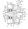
- the water pump is attached to a side of a cylinder block (not shown) of the internal combustion engine by bolts, and has a pump housing 1 having a pump chamber 2 in a front end on the cylinder block side, A pulley 4 rotatably supported by a ball bearing 3 which is a single bearing portion on the front end side of the pump housing 1, and is inserted into the pump housing 1, and one end portion 5 a is coupled to the pulley 4.
- the mechanical seal 7 seals between the pump chamber 2 and the ball bearing 3.
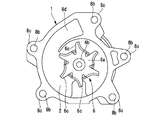
- the pump housing 1 is integrally formed of an aluminum alloy material, the housing body 8 on the pump chamber 2 side is formed in a deformed annular shape, and a cylindrical portion having a step diameter is formed on the rear end side of the housing body 8. 9 is integrated.
- the housing body 8 is formed with a flat annular mounting surface 8a that abuts against a flat portion at the side of the cylinder block at the front end, and a mounting bolt that is screwed and fixed to the cylinder block is inserted through the outer periphery.
- a plurality of bosses 8c constituting the bolt holes 8b are provided.
- a discharge port 8d that discharges cooling water flowing into the pump chamber 2 from a radiator-side intake port (not shown) into the water jacket in the cylinder block as the impeller 6 rotates is provided inside the housing body 8. Is formed.
- the cylindrical portion 9 includes a large-diameter portion 9a on the pump chamber 2 side, a medium-diameter portion 9b extending from the large-diameter portion 9a in the direction of the ball bearing 3, And a small-diameter portion 9c extending from the middle-diameter portion 9b to one end side of the drive shaft 5.
- a drain hole 10 through which water droplets of cooling water leaking from the mechanical seal 7 flow downward is formed penetrating in the vertical direction, and below the drain hole 10
- a drain chamber 11 for storing water droplets dripped from the drain hole 10 is formed across the inside of the large diameter portion 9a.
- the drain chamber 11 is liquid-tightly sealed at its lower end opening with a drain cap 12.
- an unillustrated air opening hole for discharging the steam of the cooling water leaked from the mechanical seal 7 or stored in the drain chamber 11 or the like to the outside. It has been drilled. Furthermore, an annular space chamber 13 is formed between the inner diameter portion 9b and the drive shaft 5 between the drain hole 10 and the air opening hole. Is communicated in the vertical direction. An air communication hole (not shown) that connects the air opening hole and the outside is formed on the outer periphery of the medium diameter portion 9b.
- the ball bearing 3 is a general one, and as shown in FIGS. 1 and 2, an inner ring 3a press-fitted into the small diameter portion 9c and an inner peripheral surface of a cylindrical base portion 4b of the pulley 4 which will be described later.
- the outer ring 3b is press-fitted into 4g, and a plurality of balls 3c are provided between the inner ring 3a and the outer ring 3b so as to roll freely through a cage.
- the inner ring 3a is positioned in the axial direction by an annular protrusion 9d provided at the front end edge of the middle diameter portion 9b of the cylindrical portion 9 while the maximum press-fitting position in the axial direction of the inner ring 3a.
- the inner ring 3a is naturally positioned in the axial direction by press-fitting into the pulley 4.
- the both seal members 14 and 15 are arranged to face each other so as to cover both sides of the ball bearing 3 in the axial direction.
- the first seal member 14 is fixed in a sandwiched state between the annular projecting portion 9d on the side of the intermediate diameter cylindrical portion 9b and one end surface of the inner ring 3a.
- the second seal member 15 is fixed in a sandwiched state between the second seal member 15 and the other end surface of the inner ring 3a by a retainer 16 as a holding member.
- the pulley 4 is a flange that is a disk-shaped end wall formed by bending a metal plate, which will be described later, into a predetermined shape by press molding, and disposed on one end side of the drive shaft 5.
- the flange wall 4a is integrally formed with a bottomed cylindrical portion 4e in which one end portion 5a of the drive shaft 5 is press-fitted and fixed at a central position.
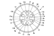
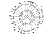
- six through holes 17 are formed so as to penetrate in the axial direction at substantially equal intervals in the circumferential direction.
- the cylindrical portion 4e is formed with an air vent hole 4f through which air is vented when the one end portion 5a of the drive shaft 5 is press-fitted into the center position of the bottom wall.
- a transmission belt wound around a driving pulley fixed to the distal end portion of a crankshaft (not shown) is wound around an outer periphery formed in a tooth shape having a corrugated cross section to transmit a rotational force. It is like that.
- the drive shaft 5 has an outer peripheral surface formed of, for example, a ferrous metal material with a stepped diameter, and is joined to the center of the flange wall 4a from the axial direction, The other end portion 5b is press-fitted and fixed in the center of the impeller 6 from the axial direction, and a small-diameter shaft portion 5c is formed at a substantially central position in the axial direction.
- the one end portion 5a and the other end portion 5b have substantially the same outer diameter, but the outer diameter of the small diameter shaft portion 5c is smaller than the outer diameters of the both end portions 5a and 5b.
- the small-diameter shaft portion 5c is provided adjacent to the annular space chamber 13, and the water leaking from the mechanical seal 7 and traveling along the outer peripheral surface is separated by both axial step edges 5d and 5e to thereby form the annular space chamber. 13 is led into the drain chamber 11 through the drain hole 10.
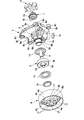
- the impeller 6 is integrally formed of, for example, a metal material such as an aluminum alloy material. As shown in FIGS. 1 to 3, the impeller 6 is integrally formed in a substantially disc-like base portion 6a and a central portion on the front side of the base portion 6a from the axial direction.
- the cylindrical fixing portion 6b is provided in a protruding manner, and the eight blade portions 6c are formed radially from the outer peripheral surface of the cylindrical fixing portion 6b.
- the base 6a is formed to have a predetermined thickness, and rotates with a gap on the rear surface of the pump chamber 2.
- the cylindrical fixing portion 6b is formed with a fixing hole 6d into which the other end portion 5b of the drive shaft 5 is press-fitted in the internal axis direction.
- the mechanical seal 7 is a general one, and includes a cartridge portion 7a fixed to the inner peripheral surface of the medium diameter portion 9b of the cylindrical portion 9, and a sleeve 7b supported on the outer peripheral surface of the drive shaft 5. And a seal portion (not shown) which is provided between the inner peripheral side of the cartridge portion 7a and the outer peripheral side of the sleeve 7b and slides.
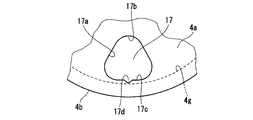
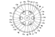
- each through hole 17 formed in the flange wall 4a of the pulley 4 is formed entirely on the outer peripheral side of the flange wall 4a, and has a shape of each inner peripheral surface 17a.
- each top surface 17b is directed toward the center of the cylindrical portion 4e, and each arc-shaped bottom surface 17c is disposed close to the inner peripheral surface 4g of the cylindrical base portion 4b.
- the arc-shaped bottom surfaces 17c are arranged close to each other along the circular inner peripheral surface 4g of the cylindrical base portion 4b.
- a passage groove 17d is formed continuously at a substantially central position in the circumferential direction of each bottom surface 17c. As shown in FIGS. 4 and 5, each passage groove 17d is formed in a substantially V-shaped cross section on the outer end edge of each through hole 17 in the radial direction of the flange wall 4a, and the deepest portion (tip portion). Is formed at the same position as the formation position of the inner peripheral surface 4g of the cylindrical base 4b.
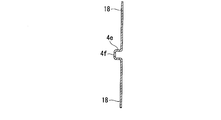
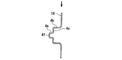
- the cylindrical portion 4e and the air vent hole 4f are simultaneously formed in the center of a disk-shaped pulley molded body 18 made of iron-based metal by a press jig of a press molding machine. .
- a disk-shaped flange wall 4a and a cylindrical base portion 4b on the outer periphery thereof are simultaneously formed by a pressing jig.
- the connecting wall 4c and the belt mounting portion 4d are formed by a different pressing jig. Thereby, almost the entire outer shape of the pulley molded body 18 is molded.
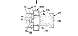
- the outer end side of the pulley molded body 18 is supported by the support jig 19 from the axial direction.
- the support jig 19 is formed at a position where the fitting support groove 19a in which the cylindrical portion 4e is fitted and supported at the center and the through holes 17 on the outer peripheral side of the fitting support groove 19a are formed. 6 insertion holes 19b.
- the punching jig 20 is inserted into the cylindrical base 4b from the right side of the pulley molded body 18 fixedly supported on the support jig 19 in advance on the left side in the figure.
- the six through holes 17 are formed by punching.
- the punching jig 20 is composed of a disc-shaped base portion 20a and six punches 20b protruding from the front end of the base portion 20a.
- Each punch 20b has a cross-sectional shape for forming the through-hole 17.
- the triangular rice ball shape and the V-shape for forming the passage groove 17d are integrally formed. Further, when the diameter of the arc locus connecting each outer peripheral edge of each punch 20b is formed slightly smaller than the inner diameter of the inner peripheral surface 4g of the cylindrical base 4b, and inserted into the cylindrical base 4b, The outer peripheral edge of each punch 20b is not in contact with the inner peripheral surface 4g.
- the passage groove 17b forming portion is formed smaller than the through hole 17 forming portion, and the width length of the passage groove 17d forming portion is It forms so that it may become continuously small toward the radial direction outer side of the flange wall 4a.
- each through hole 17 is formed on the outer peripheral side of the flange wall 4a, and the tip of each passage groove 17d is positioned at the same position as the inner peripheral surface 4g of the cylindrical base 4b. Since it formed, the water, dust, etc. which have the inside of the cylindrical base part 4b can be discharged
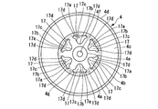
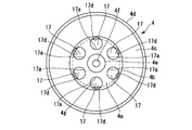
- Each of the through holes 17 of the second embodiment shown in FIG. 12 is formed in a circular shape, is disposed close to the inner peripheral surface 4g of the cylindrical base 4b, and has a diameter of each inner peripheral surface 17a.
- a passage groove 17d having a substantially V-shaped cross section is formed at the outer edge in the direction.
- Each passage groove 17d has a tip portion formed at the same position as the inner peripheral surface 4g of the cylindrical base portion 4b.
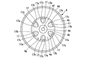
- Each of the through holes 17 of the third embodiment shown in FIG. 13 is formed in a square shape, is disposed close to the inner peripheral surface 4g of the cylindrical base 4b, and is located outside the inner peripheral surface 17a.
- a channel groove 17d having a substantially V-shaped cross section is formed in the bottom surface 17c of the flange wall 4a, that is, the bottom surface 17c of the radially outer edge of the flange wall 4a.
- Each passage groove 17d has a tip portion formed at the same position as the inner peripheral surface 4g of the cylindrical base portion 4b.
- Each through hole 17 of the fourth embodiment shown in FIG. 14 is formed in a long hole shape extending from the center P of the flange wall 4a along the radial direction, and has a circular top surface 17b on the inner peripheral side.
- a passage groove 17d is formed at the tip extending in the radial direction.
- Each passage groove 17d is formed in a substantially U shape, and each leading edge is formed at the same position as the inner peripheral surface 4g of the cylindrical base portion 4b.
- Each of the through holes 17 of the fifth embodiment shown in FIG. 15 has an inner peripheral surface 17a formed in a substantially cap shape and is disposed close to the inner peripheral surface 4g of the cylindrical base portion 4b.
- the top surface 17b is directed to the center P of the flange wall 4a, and two passage grooves 17d and 17d are formed at both ends of the bottom surface 17c corresponding to the flange portion.
- Each of the passage grooves 17d, 17d is formed in a substantially U-shaped cross section, and each end edge is formed at the same position as the inner peripheral surface 4g of the cylindrical base portion 4b.
- Each through-hole 17 of the sixth embodiment shown in FIG. 16 is formed in a substantially triangular shape and is disposed in the vicinity of the inner peripheral surface 4g of the cylindrical base portion 4b, and each top surface 17b is formed in the flange.
- a channel groove 17d is formed on one side of the bottom surface 17c and is directed to the center P of the wall 4a.
- Each of the passage grooves 17d is formed in a substantially U shape, and the tip portion is formed at the same position as the inner peripheral surface 4g of the cylindrical base portion 4b.
- each through-hole 17 of the seventh embodiment shown in FIG. 17 has each inner surface 17a shaped like a triangular rice ball like the first embodiment, and each top surface 17b oriented toward the center of the flange wall 4a.
- Each bottom surface 17c formed on the outer peripheral portion side of the flange wall 4a, and each bottom surface 17c is formed at the same position as the inner peripheral surface 4g of the cylindrical base portion 4b. That is, as in the first to sixth embodiments, the passage groove is not formed at the same position as the inner peripheral surface 4g, but each bottom surface 17c itself is formed at the same position as the formation position of the inner peripheral surface 4g. is there.
- the water that has entered the inside of the cylindrical base 4b is discharged while being guided to the outside through the bottom surface 17c having a large area of the through-hole 17, so that the flow resistance is reduced and discharged.
- the performance is further improved.
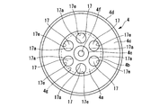
- Each through hole 17 of the eighth embodiment shown in FIG. 18 has an inner peripheral surface 17a formed in a circular shape as in the second embodiment, and an outer edge 17e of the inner peripheral surface 17a is an inner periphery of the cylindrical base portion 4b. It is formed at the same position as the surface 4g. That is, a passage groove is not formed as in the second embodiment, and the passage groove is not formed at the same position as the inner peripheral surface 4g, but each outer edge 17e itself is defined as a position where the inner peripheral surface 4g is formed. They are formed at the same position.
- the water that has entered the inside of the cylindrical base 4b is discharged while being guided to the outside through the outer edge 17e of the through hole 17 having a relatively large area, so that the flow resistance is low. Discharge performance is further improved.
- [Ninth and Tenth Embodiments] 19 and 20 show the ninth and tenth embodiments of the present invention, in which the arrangement and shape of the through holes 17 are further changed.
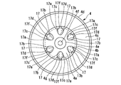
- each through-hole 17 of the ninth embodiment shown in FIG. 19 has each shape of the inner peripheral surface 17a formed in a raindrop shape, each top surface 17b oriented toward the center of the flange wall 4a, and the diameter of the flange wall 4a.
- Each bottom surface is formed on the outer end side in the direction, and a passage groove 17d is formed by cutting out the approximate center of each bottom surface in a circular arc shape.
- the passage groove 17d is formed at a position further outside the inner peripheral surface 4g of the cylindrical base portion 4b. That is, the passage groove is not formed at the same position as the inner peripheral surface 4g as in the above embodiments, but is a step surface that is one step lower than the inner peripheral surface 4g.
- the water that has entered the inside of the cylindrical base 4b is discharged while being guided to the outside through the passage groove 17d having a large area of the through hole 17 and one step lower.
- the flow rate is increased and the discharge performance is further improved.
- This unique configuration can maintain good discharge performance regardless of the position of each through hole 17 when the pump is stopped.
- the basic shape of the inner peripheral surface 17a is formed in a circular shape, and a passage groove 17d cut out in an arc shape is formed on the outer end side in the radial direction. Yes.
- the passage groove 17d is formed at a position further outside the inner peripheral surface 4g of the cylindrical base portion 4b, as in the ninth embodiment. That is, the step surface is one step lower than the inner peripheral surface 4g.
- FIG. 21 shows an eleventh embodiment.
- the basic shape and the formation position of the inner peripheral surface 17a of each through hole 17 are the same as those of the first embodiment, and the top surface is formed in a triangular rice ball shape. 17b and a bottom surface 17c, a passage groove 17d is formed from the bottom surface 17c toward the outside in the radial direction.
- the passage groove 17d is formed in a rectangular shape that is cut out from the bottom surface 17c toward the radially outer side, and each outer end edge 17f extends beyond the inner peripheral surface 4g of the cylindrical base portion 4b. The whole is extended in the radial direction to the outer peripheral surface and formed into a bowl shape.
- water or the like that has entered the inside of the cylindrical base 4b flows directly from the lower part of the inner peripheral surface 4g of the cylindrical base 4b into the passage groove 17d of the through hole 17 and continues downward. It flows down and is discharged outside. For this reason, the discharge properties of water and the like are further improved.
Landscapes
- Engineering & Computer Science (AREA)
- Mechanical Engineering (AREA)
- General Engineering & Computer Science (AREA)
- Chemical & Material Sciences (AREA)
- Combustion & Propulsion (AREA)
- Structures Of Non-Positive Displacement Pumps (AREA)
- Physics & Mathematics (AREA)
- Thermal Sciences (AREA)
Abstract
Description
〔第1実施形態〕
このウォータポンプは、自動車のラジエータと内燃機関の間で冷却水である不凍液(エチレングリコール)を循環させる冷却装置に適用されている。
〔プーリのプレス成形工程(ウォータポンプの製造方法)〕
以下、前記プーリ4のプレス成形による成形工程について、図6~図11に基づいて説明する。
〔第2~第6実施形態〕
図12~図16は本発明の第2~第6実施形態を示し、前記透孔17の形状を変更したものである。
〔第7,第8実施形態〕
図17,図18は本発明の第7,第8実施形態を示し、前記透孔17の配置を変更すると共に、通路溝を廃止したものである。
〔第9、第10実施形態〕
図19、図20は本発明の第9、第10実施形態を示し、前記透孔17の配置や形状をさらに変更したものである。
〔第11実施形態〕
図21は第11実施形態を示し、この実施形態では各透孔17の内周面17aの基本形状や形成位置が第1実施形態のものと同一で、三角おむすび状に形成されて、頂面17b、底面17cを有しているが、この底面17cから径方向外側に向かって通路溝17dが形成されている。
Claims (19)
- 軸方向の一端側に円筒部を有するポンプハウジングと、
該ポンプハウジング内で回転自在に支持された駆動軸と、
該駆動軸の一端部に固定された円盤状の端壁及び該端壁の外周縁に一体に結合されて前記円筒部を囲繞するように設けられた筒状基部を有するプーリと、
前記筒状基部と前記円筒部との間に介装されて、前記駆動軸を回転自在に軸受けする軸受部と、
前記駆動軸の他端部に一体回転可能に設けられたインペラと、
を備えたウォータポンプであって、
前記端壁に、該端壁の内外を連通する複数の透孔を軸方向に沿って形成すると共に、前記各透孔の内周面の径方向外端縁に、径方向外側に向かって通路溝を形成したことを特徴とするウォータポンプ。 - 請求項1に記載のウォータポンプにおいて、
前記通路溝は、前記筒状基部の内周面にほぼ沿って形成されていることを特徴とするウォータポンプ。 - 請求項2に記載のウォータポンプにおいて、
前記通路溝の開口面積は、前記透孔の開口面積よりも小さいことを特徴とするウォータポンプ。 - 請求項3に記載のウォータポンプにおいて、
前記通路溝は、幅長さが前記端壁の内側から外側に向かって小さくなるように形成されていることを特徴とするウォータポンプ。 - 請求項4に記載のウォータポンプにおいて、
前記透孔は、幅長さが前記端壁の内側から外側に向かって大きくなるように形成されていることを特徴とするウォータポンプ。 - 請求項5に記載のウォータポンプにおいて、
前記透孔は、三角おむすび状に形成されていることを特徴とするウォータポンプ。 - 請求項4に記載のウォータポンプにおいて、
前記各透孔は、前記端壁の周方向に等間隔位置に形成されていることを特徴とするウォータポンプ。 - 請求項7に記載のウォータポンプにおいて、
前記透孔は、円形状に形成されていることを特徴とするウォータポンプ。 - 請求項7に記載のウォータポンプにおいて、
前記透孔は、楕円形状に形成されていることを特徴とするウォータポンプ。 - 請求項7に記載のウォータポンプにおいて、
前記透孔は、矩形状に形成されていることを特徴とするウォータポンプ。 - 請求項3に記載のウォータポンプにおいて、
前記通路溝は、円弧状に形成されていることを特徴とするウォータポンプ。 - 請求項11に記載のウォータポンプにおいて、
前記通路溝は、複数形成されていることを特徴とするウォータポンプ。 - 請求項1に記載のウォータポンプにおいて、
前記軸受部は、内輪が前記円筒部に固定され、外輪が前記筒状基部に固定された単一のボールベアリングによって構成されていることを特徴とするウォータポンプ。 - 軸方向の一端側に円筒部を有するポンプハウジングと、
該ポンプハウジング内に回転自在に支持された駆動軸と、
該駆動軸の一端部に固定された円盤状の端壁及び該端壁の外周縁に一体に結合されて前記円筒部を囲繞するように設けられた筒状基部を有するプーリと、
前記筒状基部と前記円筒部との間に介装されて、前記駆動軸を回転自在に軸受けする軸受部と、
前記駆動軸の他端部に一体回転可能に設けられたインペラと、
前記端壁に軸方向に沿って形成され、前記端壁の内外を連通する複数の透孔と、
前記各透孔の内周面の径方向外端縁に前記筒状基部の内周面にほぼ沿って形成された通路溝と、
を備えたウォータポンプの製造方法であって、
円盤状の金属プレートをプレス成形によって折曲することにより前記プーリの原形を成形する工程と、
原形を成形した後に、プレス治具によって前記透孔と通路溝を合わせた形状に打ち抜き加工する工程と、を有することを特徴とするウォータポンプの製造方法。 - 請求項14に記載のウォータポンプの製造方法において、
前記打ち抜き加工する工程では、前記透孔と通路溝をプレス治具によって前記筒状基部の内側から打ち抜くことを特徴とするウォータポンプの製造方法。 - 請求項15に記載のウォータポンプの製造方法において、
前記通路溝を形成するプレス治具の断面積は、前記透孔を形成するプレス治具の断面積よりも小さいことを特徴とするウォータポンプの製造方法。 - 請求項14に記載のウォータポンプの製造方法において、
前記通路溝を打ち抜くプレス治具は、第2工程において前記筒状基部の内周面に対して点接触または線接触している部位があることを特徴とするウォータポンプの製造方法。 - 軸方向の一端側に円筒部を有するポンプハウジングと、
該ポンプハウジング内に回転自在に支持された駆動軸と、
該駆動軸の一端部に固定された円盤状の端壁及び該端壁の外周縁に一体に結合されて前記円筒部を囲繞するように設けられた筒状基部を有するプーリと、
前記筒状基部と前記円筒部との間に介装されて、前記駆動軸を回転自在に軸受けする軸受部と、
前記駆動軸の他端部に一体回転可能に設けられたインペラと、
を備えたウォータポンプであって、
前記端壁に、該端壁の内外を連通する複数の透孔を軸方向に沿って貫通形成すると共に、前記各透孔の内周面の前記端壁の径方向外側に位置する部位を、前記筒状基部の内周面にほぼ沿って形成したことを特徴とするウォータポンプ。 - 請求項18に記載のウォータポンプにおいて、
前記各透孔は、幅長さが前記端壁の中心側から外側に向かって大きくなることを特徴とするウォータポンプ。
Priority Applications (3)
| Application Number | Priority Date | Filing Date | Title |
|---|---|---|---|
| CN201480071008.5A CN105874214B (zh) | 2013-12-27 | 2014-11-04 | 水泵以及该水泵的制造方法 |
| JP2015554645A JP6113305B2 (ja) | 2013-12-27 | 2014-11-04 | ウォータポンプ及び該ウォータポンプの製造方法 |
| US15/108,102 US9810240B2 (en) | 2013-12-27 | 2014-11-04 | Water pump and method for producing water pump |
Applications Claiming Priority (2)
| Application Number | Priority Date | Filing Date | Title |
|---|---|---|---|
| JP2013270934 | 2013-12-27 | ||
| JP2013-270934 | 2013-12-27 |
Publications (1)
| Publication Number | Publication Date |
|---|---|
| WO2015098293A1 true WO2015098293A1 (ja) | 2015-07-02 |
Family
ID=53478171
Family Applications (1)
| Application Number | Title | Priority Date | Filing Date |
|---|---|---|---|
| PCT/JP2014/079208 Ceased WO2015098293A1 (ja) | 2013-12-27 | 2014-11-04 | ウォータポンプ及び該ウォータポンプの製造方法 |
Country Status (4)
| Country | Link |
|---|---|
| US (1) | US9810240B2 (ja) |
| JP (1) | JP6113305B2 (ja) |
| CN (1) | CN105874214B (ja) |
| WO (1) | WO2015098293A1 (ja) |
Families Citing this family (4)
| Publication number | Priority date | Publication date | Assignee | Title |
|---|---|---|---|---|
| US10227987B2 (en) * | 2016-12-16 | 2019-03-12 | Borgwarner Emissions Systems Llc | Valve assembly integrated into a coolant pump and method for controlling the same |
| CN110374882A (zh) * | 2019-08-09 | 2019-10-25 | 沈婷 | 一种用于制冷空调工程中的离心式水泵 |
| CN110454407A (zh) * | 2019-09-10 | 2019-11-15 | 浙江日井泵业股份有限公司 | 一种防磨损自吸泵 |
| CN115434950B (zh) * | 2022-09-30 | 2024-07-30 | 赛力斯集团股份有限公司 | 水泵总成 |
Citations (4)
| Publication number | Priority date | Publication date | Assignee | Title |
|---|---|---|---|---|
| JPS63302200A (ja) * | 1987-05-14 | 1988-12-09 | エスカーエフ ゲーエムベーハー | ポンプなどの駆動装置 |
| JPH04262096A (ja) * | 1990-12-28 | 1992-09-17 | Honda Motor Co Ltd | ウォータポンプ |
| JPH0687767U (ja) * | 1993-05-31 | 1994-12-22 | エヌティエヌ株式会社 | プーリ装置 |
| JP2012112342A (ja) * | 2010-11-26 | 2012-06-14 | Hitachi Automotive Systems Ltd | ウォータポンプ |
Family Cites Families (8)
| Publication number | Priority date | Publication date | Assignee | Title |
|---|---|---|---|---|
| US5217350A (en) | 1990-12-28 | 1993-06-08 | Honda Giken Kogyo Kabushiki Kaisha | Water pump |
| CN2434460Y (zh) * | 2000-04-14 | 2001-06-13 | 赵喜安 | 潜水泵上端导流盖 |
| JP2004116486A (ja) | 2002-09-30 | 2004-04-15 | Hitachi Unisia Automotive Ltd | ウォーターポンプ |
| DE102004060904A1 (de) * | 2004-12-17 | 2006-06-29 | Robert Bosch Gmbh | Förderaggregat |
| CN100453818C (zh) * | 2006-03-03 | 2009-01-21 | 山东大学 | 一种翼型离心叶轮制造工艺方法 |
| JP5197722B2 (ja) * | 2010-11-26 | 2013-05-15 | 日立オートモティブシステムズ株式会社 | ウォータポンプ |
| JP5688349B2 (ja) * | 2011-09-12 | 2015-03-25 | 株式会社クボタ | 水冷エンジン |
| JP5713870B2 (ja) * | 2011-10-18 | 2015-05-07 | 日立オートモティブシステムズ株式会社 | 内燃機関のウォータポンプ |
-
2014
- 2014-11-04 WO PCT/JP2014/079208 patent/WO2015098293A1/ja not_active Ceased
- 2014-11-04 US US15/108,102 patent/US9810240B2/en active Active
- 2014-11-04 CN CN201480071008.5A patent/CN105874214B/zh not_active Expired - Fee Related
- 2014-11-04 JP JP2015554645A patent/JP6113305B2/ja active Active
Patent Citations (4)
| Publication number | Priority date | Publication date | Assignee | Title |
|---|---|---|---|---|
| JPS63302200A (ja) * | 1987-05-14 | 1988-12-09 | エスカーエフ ゲーエムベーハー | ポンプなどの駆動装置 |
| JPH04262096A (ja) * | 1990-12-28 | 1992-09-17 | Honda Motor Co Ltd | ウォータポンプ |
| JPH0687767U (ja) * | 1993-05-31 | 1994-12-22 | エヌティエヌ株式会社 | プーリ装置 |
| JP2012112342A (ja) * | 2010-11-26 | 2012-06-14 | Hitachi Automotive Systems Ltd | ウォータポンプ |
Also Published As
| Publication number | Publication date |
|---|---|
| JPWO2015098293A1 (ja) | 2017-03-23 |
| CN105874214B (zh) | 2018-10-02 |
| US20160319831A1 (en) | 2016-11-03 |
| JP6113305B2 (ja) | 2017-04-12 |
| CN105874214A (zh) | 2016-08-17 |
| US9810240B2 (en) | 2017-11-07 |
Similar Documents
| Publication | Publication Date | Title |
|---|---|---|
| JP5197722B2 (ja) | ウォータポンプ | |
| JP6113305B2 (ja) | ウォータポンプ及び該ウォータポンプの製造方法 | |
| JP5589532B2 (ja) | ベーンポンプ | |
| US8632431B2 (en) | Drive wheel of an auxiliary unit belt drive of an internal combustion engine | |
| US8813705B2 (en) | Hydraulic support element | |
| JP5087607B2 (ja) | 自動車用ウォータポンプ及び軸受構造 | |
| US20150023798A1 (en) | Blade member for fluid pump | |
| JP4895145B2 (ja) | 車両用回転電機 | |
| EP3190309A1 (en) | Balance shaft friction damper | |
| JPH09229214A (ja) | 四方切換弁 | |
| KR20150100307A (ko) | 차량용 쿨링팬 | |
| US10273959B2 (en) | Pump assembly | |
| JP5925612B2 (ja) | ウォータポンプ | |
| JP2012112342A (ja) | ウォータポンプ | |
| EP1988293B1 (en) | Coolant pump | |
| JP6266388B2 (ja) | ウォータポンプ | |
| JP5993289B2 (ja) | ウォータポンプ | |
| KR20170114076A (ko) | 자동차용 댐퍼 풀리 조립체 | |
| KR101504611B1 (ko) | 조립형 텐션풀리 | |
| KR102559572B1 (ko) | 회전샤프트용 씰 | |
| JP2008182814A (ja) | 回転電機のハウジングおよびその製造方法 | |
| JP2007040210A (ja) | 遠心ポンプと該遠心ポンプ用インペラの製造方法及び遠心ポンプ用インペラ | |
| JP2011214520A (ja) | ピストンポンプ | |
| KR101295194B1 (ko) | 휠 베어링용 실링 캡 | |
| JP4851423B2 (ja) | トルクコンバータ及びプレス装置 |
Legal Events
| Date | Code | Title | Description |
|---|---|---|---|
| 121 | Ep: the epo has been informed by wipo that ep was designated in this application |
Ref document number: 14875201 Country of ref document: EP Kind code of ref document: A1 |
|
| ENP | Entry into the national phase |
Ref document number: 2015554645 Country of ref document: JP Kind code of ref document: A |
|
| WWE | Wipo information: entry into national phase |
Ref document number: 15108102 Country of ref document: US |
|
| NENP | Non-entry into the national phase |
Ref country code: DE |
|
| 122 | Ep: pct application non-entry in european phase |
Ref document number: 14875201 Country of ref document: EP Kind code of ref document: A1 |