WO2015097963A1 - 撮像装置およびその制御方法 - Google Patents
撮像装置およびその制御方法 Download PDFInfo
- Publication number
- WO2015097963A1 WO2015097963A1 PCT/JP2014/005566 JP2014005566W WO2015097963A1 WO 2015097963 A1 WO2015097963 A1 WO 2015097963A1 JP 2014005566 W JP2014005566 W JP 2014005566W WO 2015097963 A1 WO2015097963 A1 WO 2015097963A1
- Authority
- WO
- WIPO (PCT)
- Prior art keywords
- bit
- gain
- imaging
- signal
- bits
- Prior art date
- Legal status (The legal status is an assumption and is not a legal conclusion. Google has not performed a legal analysis and makes no representation as to the accuracy of the status listed.)
- Ceased
Links
Images




Classifications
-
- H—ELECTRICITY
- H04—ELECTRIC COMMUNICATION TECHNIQUE
- H04N—PICTORIAL COMMUNICATION, e.g. TELEVISION
- H04N5/00—Details of television systems
- H04N5/30—Transforming light or analogous information into electric information
- H04N5/32—Transforming X-rays
-
- H—ELECTRICITY
- H04—ELECTRIC COMMUNICATION TECHNIQUE
- H04N—PICTORIAL COMMUNICATION, e.g. TELEVISION
- H04N23/00—Cameras or camera modules comprising electronic image sensors; Control thereof
- H04N23/30—Cameras or camera modules comprising electronic image sensors; Control thereof for generating image signals from X-rays
-
- H—ELECTRICITY
- H04—ELECTRIC COMMUNICATION TECHNIQUE
- H04N—PICTORIAL COMMUNICATION, e.g. TELEVISION
- H04N25/00—Circuitry of solid-state image sensors [SSIS]; Control thereof
- H04N25/50—Control of the SSIS exposure
- H04N25/57—Control of the dynamic range
- H04N25/59—Control of the dynamic range by controlling the amount of charge storable in the pixel, e.g. modification of the charge conversion ratio of the floating node capacitance
Definitions
- the present invention relates to an imaging apparatus that captures a subject and a control method thereof.
- an X-ray imaging apparatus (FPD: Flat Panel Detector) that converts X-ray information into electric charges using an X-ray detector in which fine solid-state image sensors are arranged as pixels in a two-dimensional grid.
- FPD Flat Panel Detector
- the amount of light is converted into a charge by a photodiode for each pixel during one imaging, and the charge is transferred to a capacitor to be converted into a voltage proportional to the X-ray dose rate.
- X-ray information is obtained by reading the voltage between the electrodes of this capacitor.
- the FPD amplifies the voltage between the capacitor electrodes with an amplifier, converts the amplified signal into a digital value with an AD converter, and transfers the converted signal to an external processing device (for example, a personal computer (PC)).
- an external processing device for example, a personal computer (PC)
- the signal output from the FPD is subjected to image processing by a PC or the like and displayed on a display or the like.
- Patent Document 1 captures a plurality of images by changing the exposure amount, selects data having the highest signal-to-noise ratio for each pixel, and synthesizes one image. It discloses that a synthesized image is transferred to a PC.
- Patent Document 1 it is necessary to configure a circuit that selects data having the highest signal-to-noise ratio for each pixel in the FPD, which increases the manufacturing cost of the FPD that is the imaging unit.
- the present invention has been made in view of the above problems, and according to an embodiment of the present invention, an imaging apparatus capable of transferring a high dynamic range image at a high frame rate and a control method thereof are provided. .
- an imaging apparatus has the following arrangement. That is, An imaging means having a plurality of imaging elements and outputting an imaging signal obtained with a plurality of gains; Conversion means for converting an imaging signal output from the imaging means into a quantized value represented by a bit string of a predetermined length; Selecting means for selecting a bit to be synthesized used for synthesizing an imaging signal with respect to a bit string representing quantized values acquired at the plurality of gains;
- the block diagram which shows the structural example of an X-ray detection part.
- the block diagram which shows the structural example of an X-ray imaging apparatus.
- 6 is a flowchart showing imaging processing by the X-ray imaging apparatus.
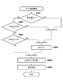
- the flowchart which shows the bit selection process of 1st Embodiment.
- the figure which shows an example of the bit selection by a bit selector.
- the figure which shows the weighting addition coefficient of a high gain signal and a low gain signal.
- the flowchart which shows the bit selection process of 2nd Embodiment. The figure which shows the relationship between a signal, a signal noise ratio, and a dose.
- the flowchart which shows the bit selection process of 4th Embodiment. The figure which shows the weighting addition coefficient of a high gain signal and a low gain signal.
- the present invention is not limited to the X-ray imaging apparatus, and is applied to, for example, a radiation imaging apparatus that captures a radiographic image of a subject using other radiation (for example, ⁇ rays, ⁇ rays, ⁇ rays, etc.) Is also possible.
- the present invention can also be applied to imaging apparatuses other than radiation imaging apparatuses such as digital single-lens reflex cameras and television cameras.
- FIG. 2 is a diagram illustrating an overall configuration of the X-ray imaging apparatus 200 according to the first embodiment.
- the X-ray imaging apparatus 200 is used particularly for medical purposes.
- the X-ray irradiation unit 201 irradiates the subject P with X-rays under the control of the imaging control unit 204.
- the X-ray irradiation unit 201 includes an X-ray generation unit 2011 (tube) that generates X-rays and a collimator 2012 that defines a beam divergence angle of the X-rays generated by the X-ray generation unit 2011.
- the X-ray detection unit 202 has an FPD, detects X-rays transmitted through the subject P, and generates X-ray image data.
- the X-ray detection unit 202 transmits the generated X-ray image data to the image processing unit 205. Details of the configuration of the X-ray detection unit 202 will be described later with reference to FIG.
- the imaging condition setting unit 203 has an input interface for an operator to input imaging conditions such as an imaging region, an X-ray dose irradiated to the subject, a frame rate, and binning.
- the shooting condition setting unit 203 transmits information indicating the shooting conditions input by the operator via the input interface to the shooting control unit 204.
- the imaging control unit 204 controls the X-ray irradiation unit 201, the X-ray detection unit 202, and the image processing unit 205 based on information from the imaging condition setting unit 203.
- the image processing unit 205 performs processing such as synthesis processing, gradation processing, and noise reduction processing for combining a plurality of images into one image on the X-ray image data transmitted from the X-ray detection unit 202,
- the processed X-ray image data is transmitted to the image display unit 206.
- the image display unit 206 outputs the image information transmitted from the image processing unit 205 to a monitor or the like.
- the frame rate of the image output from the X-ray detection unit 202 to the image processing unit 205 is limited due to the limitation of the data transfer rate of communication from the X-ray detection unit 202 to the image processing unit 205.
- the image processing unit 205 is included as a configuration of the X-ray imaging apparatus 200, but is not limited thereto.
- the image processing unit 205 may be configured as an apparatus (for example, a personal computer) external to the X-ray imaging apparatus 200.
- the X-ray detection unit 202 and the image processing unit 205 are connected by a predetermined communication interface that is wired or wireless.
- FIG. 1 is a diagram illustrating a configuration example of the X-ray detection unit 202 in the X-ray imaging apparatus 200.
- an image sensor 101 includes a photodiode that converts X-ray information transmitted through a subject into a charge amount, and a plurality of image sensors 101 are two-dimensionally arranged to form an FPD.
- the gain setting unit 102 is a capacitor that converts the amount of charge converted by each image sensor 101 into a voltage.
- the gain setting unit 102 has a plurality of capacitors, and the gain (gain) at the time of changing the charge amount to the voltage can be changed by switching the combination thereof.
- the image sensor 101 and the gain setting unit 102 described above have a plurality of image sensors and constitute an image capturing unit that outputs image signals obtained with a plurality of gains.
- the AD converter 103 constitutes a conversion unit that converts the imaging signal output from the imaging unit described above into a quantized value represented by a bit string of a predetermined length. More specifically, the AD converter 103 converts the voltage (imaging signal) converted by the gain setting unit 102 into a 16-bit unsigned integer (quantized value represented by a bit string of a predetermined length). It is a converter circuit.
- the bit selector 104 selects bits to be used for combining image signals obtained with a plurality of gains from a bit string representing quantized values acquired at each of the plurality of gains set by the gain setting unit 102. select.
- the bit selector 104 selects the bit to be synthesized from the 16-bit unsigned integer digital value obtained from the AD converter 103 at each gain set by the gain setter 102 and is selected.
- the bit is supplied to the transmitter 105 as a transmission target.
- the transmitter 105 outputs the bit selected by the bit selector 104 to the image processing unit 205.
- the bit received by the transmitter 105 from the bit selector 104 is transmitted to the image processing unit 205 at the data transfer rate of the communication interface between the transmitter 105 and the image processing unit 205.
- the bit selector 104 selects a selected bit (in this example, the lower 5 bits and the lower 5 bits) from the bit string representing the quantized value of the selected gain among the plurality of gains provided by the gain setting unit 102.
- the bit string length is shortened by discarding the upper 2 bits. By shortening the bit string length transmitted in this way, it is possible to realize shooting at a higher frame rate within a restricted data transfer rate.
- the gain setting unit 102 can set two types of gains, high gain and low gain, and the ratio of these voltage gains is 32 times.
- the ratio of the system noise included in the low gain subject signal obtained from the gain setting unit 102 is 32 times higher than that of the high gain subject signal.
- a processing example for realizing a high frame rate in cine imaging will be described.
- cine imaging an image after passing through the subject includes a region from a low dose after passing through the subject, such as the mediastinum, to a region with a high dose, such as the lung field.
- the output signal of the X-ray detection unit 202 does not saturate in the high dose region, and the system noise is low in the low dose region to ensure a good signal to noise ratio.
- the bit selector 104 since the appropriate bit and the number of bits to be transmitted differ depending on the photographing application, it is desirable to switch the processing of the bit selector 104 according to the selected photographing application in a configuration in which the photographing application can be selected. A configuration in which the bit selector 104 switches the selection of bits according to a shooting application selected from a plurality of shooting applications including cine shooting and a frame rate will be described in a second embodiment.
- step S101 the photographing conditions at the time of subject photographing such as the photographing mode, the irradiation dose, and the frame rate, which are input by the operator via the input interface provided in the photographing condition setting unit 203, are received.
- the input shooting conditions are transmitted to the shooting control unit 204.
- the imaging control unit 204 determines an X-ray irradiation condition, a bit selection method, an image composition method, and an image processing method based on the received imaging condition.
- step S102 the imaging control unit 204 transmits an X-ray irradiation signal including the determined X-ray irradiation condition to the X-ray irradiation unit 201.
- the X-ray irradiation unit 201 starts generation of X-rays under designated X-ray irradiation conditions based on the received X-ray irradiation signal.
- the imaging control unit 204 alternately specifies a high gain and a low gain to the gain setting unit 102 by transmitting an imaging control signal to the X-ray detection unit 202.
- high gain and low gain imaging signals are alternately obtained from the gain setting unit 102.
- the bit selector 104 selects a bit to be used for the composition processing of the image processing unit 205 from the high gain and low gain imaging signals, and generates a bit string to be transmitted.
- the imaging control unit 204 designates a high gain to the gain setting unit 102 and transmits a high gain bit selection signal to the bit selector 104 to generate a high gain transmission bit string (steps S103 and S104). More specifically, in step S103, the gain setting unit 102 that has received the designation of high gain sets the amplification factor to high gain. Thereby, the charge amount for each pixel generated in the image sensor 101 by the X-ray irradiation is converted into a voltage for each pixel with high gain.
- the AD converter 103 converts the voltage (imaging signal) for each pixel of the high gain imaging signal into a quantized value represented by a 16-bit unsigned integer.
- step S104 the bit selector 104 receiving the high gain bit selection signal selects some bits from the bit string of a predetermined length representing the 16-bit unsigned integer for each pixel converted in step S103, and transmits the selected bit. 105.
- the bit selector 104 that has received the high gain bit selection signal truncates the lower 5 bits and the upper 2 bits from the 16-bit bit string representing the integer value obtained in step S103, thereby generating a 9-bit transmission target bit string. Select.
- the bit selected by the bit selector 104 is transmitted to the image processing unit 205 by the transmitter 105.
- a maximum value of 9 bits to be transmitted that is, all 9 bits are 1) is transmitted.
- step S201 the bit selector 104 truncates a lower-order predetermined number of bits (5 bits in the present embodiment) for each pixel of the 16-bit unsigned integer for each pixel.
- the magnification of the high gain amplification factor to the low gain amplification factor is 32.
- the truncation of the lower 5 bits corresponds to dividing the high gain quantized value by 32, and this process matches the high gain value with the low gain value.
- step S202 the bit selector 104 determines whether or not the most significant bit is 1 for the signal for each pixel after being processed in step S201. If the most significant bit is 1, the process proceeds to step S204, and otherwise, the process proceeds to step S203. In step S203, it is determined whether the second bit from the most significant bit is 1. If the second bit from the most significant bit is 1, the process proceeds to step S204. Otherwise, the process proceeds to step S205.
- step S204 the signal of all bits is converted to 1.
- the most significant bit is 1, and the process proceeds from step S202 to step S205, where 1220LSB is converted to 2047LSB.
- the second bit from the most significant bit is 1, and the process proceeds from step S203 to step S204, where 818LSB is converted to 2047LSB.
- the bit selector 104 truncates the upper predetermined number of bits (2 bits in this embodiment). As will be described later with reference to FIG. 6, when the high gain signal is 511 or more, the weighting coefficient k is 0, and the high gain signal does not contribute to the synthesis.
- step S206 the transmitter 105 built in the X-ray detection unit 202 transmits the signal for each pixel converted in step S205 to the image processing unit 205.
- the imaging control unit 204 transmits a signal for setting the gain to low gain to the gain setting unit 102 and selects the low gain bit to the bit selector 104. Send a signal. Thereby, a transmission bit string in low gain is generated (steps S105 and S106).
- step S105 the gain setting unit 102 that has received the signal to be set to low gain sets the amplification factor to low gain. Then, a 16-bit unsigned integer, which is a low gain quantized value, is obtained from the AD converter 103 by the same processing as in step S103.
- step S106 a bit to be transmitted is selected by the bit selector 104 that has received the low gain bit selection signal.
- the low gain bit selection signal is a signal instructing to select all the bits of a 16-bit unsigned integer of low gain. Therefore, the bit selector 104 transmits the signal (16-bit bit string) received from the AD converter 103 to the transmitter 105 as it is.
- the transmitter 105 receives the transmitted signal, and transmits the received signal to the image processing unit 205.
- step S107 the image processing unit 205 synthesizes the high gain and low gain subject signals received in steps S104 and S106 into one signal for each pixel, based on the image synthesis control signal received from the imaging control unit 204. To do. Details of the processing will be described with reference to FIGS.
- step S107 the image processing unit 205 adds the high gain signal H and the low gain signal L at a ratio of k ⁇ H + (1 ⁇ k) ⁇ L using the weighting coefficient k for each pixel. As shown in FIG. 6, the weighting coefficient k changes from 1 to 0 as the high gain signal changes from 255 to 511.
- the high gain signal is a bit string consisting of 9 bits at the center, with the lower 5 bits and the upper 2 bits truncated by the bit selector 104, and therefore the mixing ratio (weight) of the high gain signal of 511 or higher is 0. It is said. From another aspect, in a region where the high gain signal is 511 or more, a sufficient S / N ratio can be obtained even if a composite image is generated using only the low gain signal. Therefore, by truncating the upper 2 bits of the high gain signal in the bit selector 104, the bit string to be transmitted can be further shortened while avoiding the influence on the image quality.
- FIG. 7 shows the relationship between the high gain and low gain signals after the AD conversion in step S103 and step S105, the signal noise ratio, and the signal noise ratio after the signal is synthesized in step S107.
- a high gain signal and a low gain signal can be synthesized without generating a dose at which the signal-to-noise ratio becomes discontinuous with respect to the dose.
- step S108 the image processing unit 205 that has received the image processing signal from the imaging control unit 204 performs gradation processing and recursive processing on the subject signal for each pixel synthesized in step S107.
- the image processing unit 205 transmits the processed signal to the image display unit 206.
- step S109 the image display unit 206 converts the received information into a two-dimensional image and displays it on the display.
- the operator confirms the image data displayed on the image display unit 206 and determines whether or not to continue shooting.
- the process returns from step S110 to step S102, and the processes of steps S102 to S109 described above are repeated. If the end of imaging is instructed from the input interface, X-ray image imaging is terminated.
- the imaging apparatus includes a plurality of imaging devices, and outputs an imaging signal obtained with a plurality of gains (for example, the imaging device 101 and the gain setting unit 102).
- a conversion unit (for example, AD converter 103) that converts an imaging signal output from the imaging unit into a quantized value represented by a bit string of a predetermined length, and a bit string that represents a quantized value acquired with a plurality of gains
- a selection unit for example, bit selector 104 that selects bits to be used for combining image signals, it is possible to realize a device that captures a high dynamic range image at a high frame rate. It becomes.
- the bit selector 104 generates a bit signal (in the above example, the lower 5 bits) that is not essential for cine radiography because the X-ray quantum noise of the high gain signal is larger than the subject signal. It is automatically deleted.
- the bit signals (the upper 2 bits in the above example) that can satisfy the signal-to-noise ratio required for cine imaging even when the low gain signals are used are automatically deleted. Then, the bit string composed of the bits selected as described above in the high gain signal and all the bit strings of the low gain signal are transmitted to the image processing unit 205.
- the imaging device since it can be realized simply by providing the bit selector 104 in a general FPD, the imaging device has a high dynamic range and a high frame rate at a lower cost than the imaging device of Patent Document 1. Can be realized.
- the bit selector 104 selects the bit to be transmitted for the high gain and low gain signals so as to generate a bit string suitable for cine imaging.
- the bit selection by the bit selector 104 can be switched in accordance with the shooting application selected by the operator and the shooting frame rate.
- the X-ray dose irradiated to the subject differs depending on the imaging application such as cine imaging or fluoroscopic imaging, and the X-ray dose range of the region of interest after the subject transmission differs accordingly. Therefore, it is preferable that the X-ray detection unit 202 does not saturate in the region of interest and can appropriately select an appropriate gain and bit selection method for lowering system noise according to the imaging application.
- the shooting frame rate desired by the operator may be different. If the imaging frame rate desired by the operator is low, all bits of the acquired imaging signal can be transmitted to the image processing unit 205, and a high dynamic image with high saturation dose and low system noise can be provided to the operator. . However, when the operator requests a high frame rate, the frame rate is limited by the data transfer rate from the X-ray detection unit 202 to the image processing unit 205. Therefore, it is necessary to appropriately select the bit of the subject signal so that an image suitable for radiological image diagnosis can be provided to the operator at a high frame rate within the limitation of the data transfer rate.
- appropriate bit selection is realized by adding a condition determination function for switching the bit of a subject signal to be transmitted according to a shooting application and a shooting frame rate to the shooting control unit 204.
- the configurations of the X-ray imaging apparatus 200 and the X-ray detection unit 202 of the second embodiment are the same as those of the first embodiment (FIGS. 1 and 2).
- the X-ray imaging apparatus 200 has two imaging applications, a cine imaging application and a fluoroscopic application.
- the operation of the second embodiment will be described mainly with respect to differences from the processing of the first embodiment, using the flowchart of FIG.
- step S101 the shooting control unit 204 receives setting of shooting conditions at the time of shooting a subject including a shooting application and a shooting frame rate performed by the operator via the input interface. Based on the input imaging conditions, the imaging control unit 204 determines the selection bit mode of the subject signal transmitted from the X-ray detection unit 202 to the image processing unit 205 by the selection bit mode determination process shown in FIG. The selected bit mode determination process shown in FIG. 8 will be described below.
- step S301 the imaging control unit 204 determines whether the imaging application selected by the operator in step S101 is cine imaging. If the selected shooting application is cine shooting, the process proceeds to step S302; otherwise, the process proceeds to step S303.
- step S302 the imaging control unit 204 determines whether the imaging frame rate received in step S101 is 5 fps or less. If the shooting frame rate is 5 fps or less, the process proceeds to step S304; otherwise, the process proceeds to step S305.
- step S303 it is determined whether the shooting frame rate received in step S101 is 10 fps or less. If the shooting frame rate is 10 fps or less, the process proceeds to step S306; otherwise, the process proceeds to step S307.
- step S304 the imaging control unit 204 records “low speed cine mode” in the internal memory as the selection bit mode of the subject signal.
- steps S305, S306, and S307 “high-speed cine mode”, “low-speed fluoroscopy mode”, and “high-speed fluoroscopy mode” are stored in the internal memory as the subject signal selection bit modes, respectively.
- step S103 and step S105 is the same as that in the first embodiment.
- steps S104 and S106 the process is switched according to the selected bit mode specified by the selected bit mode determination process described above.
- the imaging control unit 204 Prior to the bit selection process in steps S ⁇ b> 104 and S ⁇ b> 106, the imaging control unit 204 transmits information on the selected bit mode recorded in the internal memory in step S ⁇ b> 101 to the bit selector 104.
- step S104 and step S106 When the low-speed cine mode is selected as the selected bit mode, the same processing as step S106 of the first embodiment is performed in step S104 and step S106. That is, the bit selector 104 selects all bits of the high-gain and low-gain imaging signals as transmission target bits, and the transmitter 105 transmits the selected bits (all bits) to the image processing unit 205.
- steps S104 and S106 processes similar to those in steps S104 and S106 of the first embodiment are performed in steps S104 and S106, respectively. That is, the bit selector 104 selects some bits of the high gain subject signal and all bits of the low gain subject signal, and the transmitter 105 transmits the selected bits to the image processing unit 205.
- step S104 processing for selecting all bits is performed in the same manner as in step S106 in the first embodiment, and all bits of the high gain subject signal are selected as transmission targets. Is done.
- step S106 the bit selector 104 performs a process of truncating the upper 3 bits of the low gain signal. A flowchart of this process is shown in FIG. The bit selector 104 sets all the lower bits to 1 if at least one of the upper 3 bits of the low gain includes 1 (steps S401, S402, S403, and S404).
- bit selector 104 discards the upper 3 bits of the low gain signal and sets a 13-bit bit string as a transmission target (step S405), and the transmitter 105 transmits the bit string to the image processing unit 205 (step S406). That is, the X-ray detection unit 202 transmits all bits of the high gain subject signal and some bits of the low gain subject signal to the image processing unit 205.
- step S104 processing similar to that in step S104 of the first embodiment is performed on the high gain subject signal.
- step S106 processing similar to that in the low-speed fluoroscopic mode is performed on the low gain subject signal.
- the bit selector 104 images a part of bits of the high gain subject signal (a bit string excluding the lower 5 bits and the upper 2 bits) and a part of bits of the low gain object signal (a bit string excluding the upper 3 bits). Select to send to processing unit 205.
- the image composition processing in step S107 in the second embodiment differs depending on the selected bit mode.
- the image processing unit 205 divides the high gain signal received in step S104 by 32. Then, the high gain signal and the low gain signal are combined into one signal by the method described in step S107 of the first embodiment.
- the upper 2 bits of the high gain signal are present and an 11-bit signal is handled, so the range in which the synthesis using the weighting coefficient is performed is different from that in FIG.
- bit string similar to that in the first embodiment is transmitted to the image processing unit 205, and thus the same processing as that described in step S107 in the first embodiment. Is synthesized.
- the composition processing in step S107 is the same as when the low-speed cine mode is selected.
- the bit string of the high gain signal has the same configuration as that of the first embodiment, and the synthesis process in step S107 is the same as the synthesis process of the first embodiment. .
- FIG. 10 and 11A show the relationship between each selected bit mode, the high gain and low gain signals after AD conversion in step S103 and step S105, the signal noise ratio, and the signal noise ratio after the signal is synthesized in step S107. This is shown in FIG. 11B.
- the low-speed cine mode is selected as the selection bit mode, the relationship shown in FIG. 10 is obtained.
- an image after passing through the subject includes a region from a low dose after passing through the subject such as the mediastinum to a region where the dose is high such as lung field. As shown in FIG.
- the high-speed cine mode when synthesizing the high-gain and low-gain signals, a good signal-to-noise ratio is maintained even in a low dose range, and it does not saturate even at a high dose, and has a high dynamic range required for cine imaging. is doing. Further, when the high-speed cine mode is selected, the same characteristics as in the first embodiment (FIG. 7) are obtained.
- the high-speed cine mode has a higher dose that can be imaged in the low-dose region than the low-speed cine mode, and the dynamic range is lower than that in the low-speed cine mode, but can be imaged at a higher frame rate than the low-speed cine mode.
- the low-speed fluoroscopy mode is selected as the selection bit mode, as shown in FIG. 11A
- a good signal-to-noise ratio is maintained in the low dose region, and fluoroscopic imaging is also performed in the high dose region. Meets the maximum dose required.
- the high-speed fluoroscopy mode is selected as the selection bit mode, as shown in FIG. 11B
- the radiographable dose in the low-dose region is higher than that in the low-speed fluoroscopy mode, and the dynamic range is lower than that in the low-speed fluoroscopy mode. descend.
- the high-speed fluoroscopy mode the number of bits to be transmitted is further reduced, and shooting at a higher frame rate is possible than in the low-speed fluoroscopy mode.
- the processing from step S108 to S110 in the second embodiment is the same as the processing from step S108 to S110 in the first embodiment.
- the second embodiment it is possible to automatically and appropriately switch the bit of the subject signal to be transmitted according to the shooting application and the shooting frame rate. Accordingly, it is possible to appropriately select the bit of the subject signal transmitted from the X-ray detection unit 202 to the image processing unit 205 according to the imaging application and the imaging frame rate selected by the operator.
- the operator can obtain an image with the maximum dynamic range within the requested frame rate, and can obtain an image that does not saturate even with the maximum dose required for each imaging method.
- the transmission target of the pixel signals acquired according to the operation mode selected by the bit selector 104 is selected.
- a configuration for switching bits will be described.
- an operator may desire a high-quality image or a high-frame-rate image depending on the procedure, and the operability is improved by enabling such switching.
- a condition determination function for switching the bit of a subject signal to be transmitted according to the selection result of the shooting application and the image quality priority mode and the frame rate priority mode is added to the shooting control unit 204.
- the configurations of the X-ray imaging apparatus 200 and the X-ray detection unit 202 of the third embodiment are the same as those of the first embodiment (FIGS. 1 and 2).
- the operation of the third embodiment is obtained by replacing the bit selection mode determination process (FIG. 8) described in the second embodiment with the bit selection mode determination process shown in the flowchart of FIG. It is the same as the form.
- the operator can select the image quality priority mode or the frame rate priority mode via the input interface of the shooting condition setting unit 203.
- step S101 of FIG. 3 when the imaging control unit 204 receives selection of the image quality priority mode or the frame rate priority mode by the operator, the shooting control unit 204 determines the selection bit mode by the process shown in FIG.
- the bit selection mode is determined as the low-speed cine or the high-speed cine according to the selection of the image quality priority mode or the frame rate priority mode by the operator (S502, S503). , S504).
- the bit selection mode is determined to be low-speed fluoroscopy or high-speed fluoroscopy according to the selection of the image quality priority mode or the frame rate priority mode by the operator (S502, S503). , S504).
- the generation of the bit string to be transmitted in the determined bit selection mode and the synthesis of the high gain and low gain subject signals are the same as in the second embodiment.
- the operator can select which of the image quality and the frame rate should be prioritized, and the bit selector 104 appropriately transmits to the image processing unit 205 according to the selection. Select a bit.
- the total number of bits of the synthesis target bit string selected in the shooting frame rate priority mode is smaller than the total number of bits of the synthesis target bit string selected in the image quality priority mode. Therefore, it is possible to improve the image quality in the image quality priority mode, and to realize a higher frame rate in the shooting frame rate priority mode. As a result, the operator can obtain a desired image both when a high-quality image is desired and when a high frame rate image is desired.
- the image processing unit 205 has a plurality of high-gain and low-gain signal combining methods, and depending on the combining method executed by the image processing unit 205, bits to be transmitted in the acquired pixel signal. Switch. By adding such a function, it becomes possible to transmit a bit string with a reduced number of bits according to the synthesis method from the X-ray detection unit 202 to the image processing unit 205, and to capture an image at a higher frame rate. It becomes possible.
- the configurations of the X-ray imaging apparatus 200 and the X-ray detection unit 202 of the fourth embodiment are the same as those of the first embodiment (FIGS. 1 and 2).
- the high-speed fluoroscopy mode is further changed according to the frame rate. 5 types of bit selection modes are used. Therefore, in the fourth embodiment, the process shown by the flowchart of FIG. 13 is executed instead of the bit selection mode determination process (FIG. 8) of the second embodiment. Accordingly, in the bit selection process in steps S104 and S106 in the flowchart shown in FIG. 3, a process different from that of the second embodiment is executed.
- Other processes are the same as those in the second embodiment, and differences from the second embodiment will be mainly described below.
- step S601 when the set shooting frame rate is greater than 10 fps, the shooting control unit 204 determines whether the set shooting frame rate is 15 fps or less (step S601). ). When the shooting frame rate is 15 fps or less, the shooting control unit 204 sets the selected bit mode to high-speed fluoroscopy A (step S602), and otherwise sets high-speed fluoroscopy B (step S603).
- Subsequent processing when classified as high-speed fluoroscopy A is the same as the high-speed fluoroscopy processing of the second embodiment.
- the weighting shown in FIG. 15 is used in the composition processing in the image processing unit 205. That is, in this embodiment, the synthesis process is changed according to the requested frame rate, and the bit selection process (steps S104 and S106) in the bit selector 104 is also changed accordingly.
- the combining process using the weighting shown in FIG. 15 when the high gain signal is 255, the signal is switched to the low gain signal. Therefore, a signal representing a high gain of 255 or higher is not required, and as a result, in this embodiment, the upper 3 bits of the high gain signal are discarded. Details of this processing are shown in the flowchart of FIG.
- step S104 the bit selector 104 performs processing of truncating the lower 5 bits and the upper 3 bits of the high gain signal as shown in FIG. That is, the bit selector 104 first truncates the lower 5 bits of the high gain signal (step S701). If 1 is included in at least one of the upper 3 bits of the high gain signal, all the lower bits are set to 1 (steps S702, S703, S704, and S705). Then, the bit selector 104 truncates the upper 3 bits of the high gain signal and sets a 13-bit bit string as a transmission target (step S706), and the transmitter 105 transmits the bit string to the image processing unit 205 (step S707).
- bit selection processing (step S106) of the bit selector 104 for the low gain signal is the same as in the high-speed fluoroscopic mode of the second embodiment (FIG. 9), and the upper 3 bits of the low gain signal are discarded.
- the weighting coefficient is stepped with the threshold value 255LSB to synthesize the high gain and low gain signals.
- the signal-to-noise ratio after the above processing changes in a stepwise manner between the high gain signal usage dose range and the low gain signal usage dose range as shown in FIG.
- the high-speed fluoroscopy B since the total number of bits transmitted from the X-ray detection unit 202 to the image processing unit 205 is smaller than that in the high-speed fluoroscopy A, imaging at a higher frame rate is possible.
- the present invention supplies a program that realizes one or more functions of the above-described embodiments to a system or apparatus via a network or a storage medium, and one or more processors in a computer of the system or apparatus read and execute the program
- This process can be realized. It can also be realized by a circuit (for example, ASIC) that realizes one or more functions.
Landscapes
- Engineering & Computer Science (AREA)
- Multimedia (AREA)
- Signal Processing (AREA)
- Transforming Light Signals Into Electric Signals (AREA)
- Measurement Of Radiation (AREA)
Abstract
撮像装置は、複数の撮像素子を有し、複数のゲインで得られる撮像信号を出力する撮像部を有する。撮像装置は、撮像部から出力された撮像信号を所定長のビット列で表される量子化値へ変換し、複数のゲインのそれぞれで取得された量子化値を表すビット列について、複数のゲインで得られた撮像信号の合成に用いられる合成対象のビットを選択する。
Description
本発明は、被写体の撮影を行う撮像装置およびその制御方法に関するものである。
近年、放射線画像診断の分野において、微細な固体撮像素子を画素として二次元格子状に配置したX線検出器を用い、X線情報を電荷に変換するX線撮影装置(FPD:Flat Panel Detector)が使われ始めている。FPDでは、一回の撮影時に画素ごとにフォトダイオードによって光量を電荷に変換し、電荷をコンデンサに移すことでX線の線量率に比例した電圧に変換する。そして、このコンデンサの電極間の電圧を読み取ることでX線情報が得られる。一般にFPDは、コンデンサの電極間の電圧を増幅器で増幅し、増幅した信号をAD変換器でディジタル値に変換し、変換後の信号を外部の処理装置(例えばパーソナルコンピュータ(PC)等)に転送する。またFPDから出力された信号はPC等で画像処理が施され、ディスプレイ等に表示される。
FPDからPCへの転送フレームレートは、FPDからPCへのデータ転送レートの制限により制限される。そのため、FPDからPCにハイゲインとローゲインの画像をそのまま転送した場合、ハイゲインまたはローゲインのみの撮影と比較して、転送できるフレームレートが半分に制限され、撮影できる最大フレームレートが半減することになる。このような課題を解決するために、特許文献1では、露光量を変えて複数枚の画像を撮像し、画素ごとに最も信号ノイズ比が高いデータを選択して一枚の画像を合成し、合成した画像をPCに転送することを開示している。
しかしながら特許文献1記載の方法では、FPD内に画素ごとに最も信号ノイズ比が高いデータを選択する回路を構成する必要があり、撮像部であるFPDの製造コストが増加してしまう。
本発明は上記課題に鑑みてなされたものであり、本発明の一実施形態によれば、高ダイナミックレンジの画像を高フレームレートで転送することが可能な撮像装置およびその制御方法が提供される。
上記の目的を達成するための本発明の一態様による撮像装置は以下の構成を備える。すなわち、
複数の撮像素子を有し、複数のゲインで得られる撮像信号を出力する撮像手段と、
前記撮像手段から出力された撮像信号を所定長のビット列で表される量子化値へ変換する変換手段と、
前記複数のゲインで取得された量子化値を表すビット列について、撮像信号の合成に用いられる合成対象のビットを選択する選択手段と、を備える。
複数の撮像素子を有し、複数のゲインで得られる撮像信号を出力する撮像手段と、
前記撮像手段から出力された撮像信号を所定長のビット列で表される量子化値へ変換する変換手段と、
前記複数のゲインで取得された量子化値を表すビット列について、撮像信号の合成に用いられる合成対象のビットを選択する選択手段と、を備える。
以上の構成によれば、高ダイナミックレンジの画像を高フレームレートで撮像する装置を実現することが可能となる。
本発明のその他の特徴及び利点は、添付図面を参照とした以下の説明により明らかになるであろう。なお、添付図面においては、同じ若しくは同様の構成には、同じ参照番号を付す。
添付図面は明細書に含まれ、その一部を構成し、本発明の実施の形態を示し、その記述と共に本発明の原理を説明するために用いられる。
X線検出部の構成例を示すブロック図。
X線撮影装置の構成例を示すブロック図。
X線撮影装置による撮影処理を示すフローチャート。
第1実施形態のビット選択処理を示すフローチャート。
ビット選択器によるビット選択の一例を示す図。
ハイゲイン信号とローゲイン信号の重み付け加算係数を示す図。
信号、信号ノイズ比、および線量の関係を示す図。
第2実施形態の選択ビットモードの決定処理を示すフローチャート。
第2実施形態のビット選択の処理を示すフローチャート。
信号、信号ノイズ比、及び線量の関係を示す図。
信号、信号ノイズ比、及び線量の関係を示す図。
信号、信号ノイズ比、及び線量の関係を示す図。
第3実施形態の選択ビットモードの決定処理を示すフローチャート。
第4実施形態の選択ビットモードの決定処理を示すフローチャート。
第4実施形態のビット選択処理を示すフローチャート。
ハイゲイン信号とローゲイン信号の重み付け加算係数を示す図。
信号、信号ノイズ比、及び線量の関係を示す図。
以下、本発明を適用した好適な実施形態のいくつかを、添付図面を参照しながら詳細に説明する。なお、以下の各実施形態の説明では、放射線の一種であるX線を用いて被写体のX線画像データの撮影を行うX線撮影装置に本発明を適用した場合を例示して説明を行う。なお、本発明は、X線撮影装置に限らず、例えば、他の放射線(例えば、α線、β線、γ線等)を用いて被写体の放射線画像の撮影を行う放射線撮影装置に適用することも可能である。また、ディジタル一眼レフカメラ、テレビカメラ等の放射線撮影装置以外の撮影装置に本発明を適用することも可能である。
<第1実施形態>
図2は、第1実施形態に係るX線撮影装置200の全体構成を示す図である。X線撮影装置200は、特に医療用として使用される。図2において、X線照射部201は、撮影制御部204の制御下で被写体PにX線を照射する。X線照射部201は、X線を発生するX線発生部2011(管球)と、X線発生部2011において発生したX線のビーム広がり角を規定するコリメータ2012を有する。X線検出部202はFPDを有し、被写体Pを透過したX線を検出し、X線画像データを生成する。X線検出部202は、生成したX線画像データを画像処理部205に送信する。X線検出部202の構成の詳細は図1により後述する。
図2は、第1実施形態に係るX線撮影装置200の全体構成を示す図である。X線撮影装置200は、特に医療用として使用される。図2において、X線照射部201は、撮影制御部204の制御下で被写体PにX線を照射する。X線照射部201は、X線を発生するX線発生部2011(管球)と、X線発生部2011において発生したX線のビーム広がり角を規定するコリメータ2012を有する。X線検出部202はFPDを有し、被写体Pを透過したX線を検出し、X線画像データを生成する。X線検出部202は、生成したX線画像データを画像処理部205に送信する。X線検出部202の構成の詳細は図1により後述する。
撮影条件設定部203は、撮影部位、被写体に照射されるX線の線量、フレームレート、ビニング等の撮影条件を操作者が入力するための入力インタフェースを有する。撮影条件設定部203は、操作者が入力インタフェースを介して入力した撮影条件を示す情報を撮影制御部204に送信する。撮影制御部204は撮影条件設定部203からの情報を基に、X線照射部201、X線検出部202、及び画像処理部205を制御する。画像処理部205は、X線検出部202から送信されたX線画像データに対して、複数枚の画像を一枚の画像に合成する合成処理、階調処理、ノイズ低減処理といった処理を施し、処理後のX線画像データを画像表示部206に送信する。画像表示部206は画像処理部205から送信された画像情報を、モニタ等に出力する。
以上の構成において、X線検出部202から画像処理部205への通信のデータ転送レートの制限により、X線検出部202から画像処理部205へ出力される画像のフレームレートが制限される。なお、本実施形態では、X線撮影装置200の構成として画像処理部205が含まれているがこれに限られるものではない。たとえば、画像処理部205をX線撮影装置200の外部の装置(例えば、パーソナルコンピュータ)として実現した構成でもよい。その場合、X線検出部202と画像処理部205との間は、有線又は無線による所定の通信インタフェースにより接続されることになる。
図1はX線撮影装置200におけるX線検出部202の構成例を示す図である。図1において、撮像素子101は被写体を透過したX線情報を電荷量に変換するフォトダイオードを含み、複数の撮像素子101が2次元に配列されてFPDを形成している。ゲイン設定器102は、各々の撮像素子101で変換された電荷量を電圧に変換するコンデンサである。ゲイン設定器102は複数のコンデンサを有しており、それらの組み合わせを切り替えることで電荷量を電圧に変える際の増幅率(ゲイン)を変更することができる。そのような構成は周知であり、ここでは詳細な説明を省略する。以上の撮像素子101およびゲイン設定器102は、複数の撮像素子を有し、複数のゲインで得られる撮像信号を出力する撮像部を構成する。
AD変換器103は、上述の撮像部から出力された撮像信号を所定長のビット列で表される量子化値へ変換する変換部を構成する。より具体的には、AD変換器103は、ゲイン設定器102で変換された電圧(撮像信号)を、16ビットの符号なし整数(所定長のビット列で表される量子化値)に変換するADコンバータ回路である。ビット選択器104は、ゲイン設定器102で設定される複数のゲインのそれぞれにおいて取得された量子化値を表すビット列から、複数のゲインで得られた撮像信号の合成に用いられる合成対象のビットを選択する。より具体的には、ビット選択器104はゲイン設定器102で設定された各ゲインにおいてAD変換器103より得られた16ビット符号なし整数のディジタル値から合成対象のビットを選択し、選択されたビットを送信対象として送信器105に供給する。
送信器105は、ビット選択器104により選択されたビットを画像処理部205に出力する。本実施形態では、送信器105と画像処理部205との間の通信インタフェースのデータ転送レートで、送信器105がビット選択器104より受信したビットを画像処理部205に送信する。本実施形態では、ビット選択器104が、ゲイン設定器102により提供される複数のゲインのうちの選択されたゲインの量子化値を表すビット列から、選択されたビット(本例では下位5ビットと上位2ビット)を破棄することによりビット列長を短縮する。このように送信されるビット列長が短縮されることにより、制約されたデータ転送レートの中でより高いフレームレートの撮影を実現することを可能としている。
以下、図3を用いて、第1実施形態によるX線撮影装置200の撮影開始から終了までの処理を説明する。第1実施形態では、ゲイン設定器102はハイゲイン、ローゲインの2種類の増幅率を設定でき、それらの電圧増幅率の比率が32倍である場合の例を説明する。この場合、ゲイン設定器102から得られたローゲインの被写体信号に含まれるシステムノイズの信号に対する比率は、ハイゲインの被写体信号に対して32倍高くなる。また、第1実施形態では、シネ撮影において高フレームレートを実現するための処理例を説明する。シネ撮影では被写体透過後の画像に、縦隔等の被写体透過後の線量が低い領域から、肺野等の線量が高い領域までが含まれる。よって高線量の領域においてX線検出部202の出力信号が飽和せず、かつ低線量の領域においてシステムノイズが低く良好な信号ノイズ比を確保できることが要求される。なお、撮影アプリケーションに応じて送信対象として適切なビットやビット数は異なるため、撮影アプリケーションを選択可能な構成では選択された撮影アプリケーションに応じてビット選択器104の処理を切り替えることが望ましい。シネ撮影を含む複数の撮影アプリケーションから選択された撮影アプリケーションやフレームレートに応じてビット選択器104がビットの選択を切り替える構成については、第2実施形態で説明する。
ステップS101では、撮影条件設定部203に設けられた入力インタフェースを介して操作者により入力された、撮影モード、照射線量、フレームレートといった被写体撮影時の撮影条件を受け付ける。入力された撮影条件は、撮影制御部204に送信される。撮影制御部204は受け付けた撮影条件を基に、X線照射条件、ビット選択方法、画像合成方法、画像処理方法を決定する。ステップS102において、撮影制御部204はX線照射部201に決定されたX線照射条件を含むX線照射信号を送信する。X線照射部201は受信したX線照射信号を基に、指定されたX線照射条件でのX線の発生を開始する。
ステップS103~S106において、撮影制御部204は、X線検出部202に撮影制御信号を送信することで、ゲイン設定器102に対してハイゲインとローゲインを交互に指定する。これにより、ゲイン設定器102からハイゲインとローゲインの撮像信号が交互に取得される。ビット選択器104は、ハイゲインとローゲインの撮像信号から、画像処理部205の合成処理に用いられるべきビットを選択し、送信対象のビット列を生成する。
まず、撮影制御部204がゲイン設定器102にハイゲインを指定し、ビット選択器104にハイゲインビット選択信号を送信して、ハイゲインの送信ビット列を生成する(ステップS103、S104)。より具体的には、ステップS103において、ハイゲインの指定を受けたゲイン設定器102は増幅率をハイゲインに設定する。これにより、X線照射により撮像素子101に生じた画素ごとの電荷量はハイゲインで画素ごとの電圧に変換される。AD変換器103は、ハイゲインの撮像信号の画素ごとの電圧(撮像信号)を、16ビットの符号なし整数で表される量子化値に変換する。
ハイゲインビット選択信号を受信しているビット選択器104は、ステップS104において、ステップS103で変換された画素ごとの16ビット符号なし整数を表す所定長のビット列から一部のビットを選択し、送信器105に提供する。本実施形態では、ハイゲインビット選択信号を受信したビット選択器104はステップS103で得られた整数値を表す16ビットのビット列から下位5ビットと上位2ビットを切り捨てることにより9ビットの送信対象のビット列を選択する。ビット選択器104で選択されたビットは送信器105により画像処理部205へ送信される。ここで、切り捨てられた上位2ビットの少なくとも何れかが“1”であった場合は、送信対象の9ビットによる最大値(すなわち、9ビットの全てが1となる)が送信される。
以下、図4及び図5を用いてステップS104によるビット選択処理の詳細を説明する。まずステップS201において、ビット選択器104は、画素ごとの16ビット符号なし整数について、画素ごとに下位の所定数のビット(本実施形態では5ビット)を切り捨てる。上述したように、ハイゲインの増幅率のローゲインの増幅率に対する倍率は32である。下位5ビットを切り捨てることはハイゲインの量子化値を32で除することに相当し、この処理によりハイゲインの値をローゲインの値と整合させている。図5の5A、5B、5Cの例では、それぞれ16ビット符号なし整数値である39045LSB、26194LSB、1449LSBの下位5ビットが切り捨てられ、それぞれ1220LSB、818LSB、45LSBに変換されている。次いでステップS202において、ビット選択器104は、ステップS201で処理された後の画素ごとの信号について、最上位ビットが1か否かを判定する。最上位ビットが1の場合はステップS204に進み、それ以外の場合はステップS203に進む。ステップS203では、最上位から2ビット目が1か否かの判定がなされる。最上位から2ビット目が1の場合はステップS204に進み、それ以外の場合はステップS205に進む。
ステップS204では、全ビットの信号が1に変換される。図5の5Aの例では最上位ビットが1であり、処理はステップS202からステップS205へ進み、1220LSBが2047LSBに変換される。また、図5の5Bの例では最上位から2ビット目が1であり、処理はステップS203からステップS204に進み、818LSBが2047LSBに変換される。ステップS205において、ビット選択器104は、上位の所定数のビット(本実施形態では2ビット)を切り捨てる。図6により後述するように、ハイゲインの信号が511以上の場合には重み付け係数kが0となり、ハイゲインの信号は合成に寄与しなくなる。すなわち、ハイゲインの信号において512以上の数値表現(上位2ビットのいずれかが1となる状態)は不要であり、本実施形態ではこのような不要なビットを予め切り捨てて、送信対象のビット数を減少させている。図5の5A、5Bの例では、2047LSBが共に511LSBに変換される。図5の5Cの例の場合は、ステップS203からステップS205へ処理が進み、上位2ビットが切り捨てられるが、ステップS205の前後で値は変化せず、45LSBのままである。次いでステップS206において、X線検出部202に内蔵された送信器105は、ステップS205で変換された画素ごとの信号を画像処理部205に送信する。
図3に戻り、ステップS103、S104によるハイゲインでのビット列の送信を終えると、撮影制御部204は、ゲイン設定器102にゲインをローゲインに設定する信号を送信し、ビット選択器104にローゲインビット選択信号を送信する。これにより、ローゲインにおける送信ビット列が生成される(ステップS105、S106)。
まず、ステップS105において、ローゲインに設定する信号を受信したゲイン設定器102は、増幅率をローゲインに設定する。そしてステップS103と同様の処理で、AD変換器103からローゲインの量子化値である16ビットの符号なし整数を得る。次いでステップS106において、ローゲインビット選択信号を受信したビット選択器104により送信対象のビットが選択される。本例では、ローゲインビット選択信号は、ローゲインの16ビット符号なし整数の全ビットを選択することを指示する信号である。したがって、ビット選択器104はAD変換器103から受信した信号(16ビットのビット列)をそのまま送信器105に送信する。そして送信器105は送信された信号を受信し、受信した信号を画像処理部205に送信する。
次にステップS107において、画像処理部205は撮影制御部204から受信した画像合成制御信号を基に、ステップS104、S106でそれぞれ受信したハイゲインとローゲインの被写体信号を、画素ごとに一つの信号に合成する。その処理の詳細を図6及び図7を用いて説明する。ステップS107において、画像処理部205は、画素ごとに、ハイゲインの信号Hとローゲインの信号Lを、重み付け係数kを用いてk×H+(1-k)×Lの割合で加算する。重み付け係数kは図6に示されるように、ハイゲインの信号が255から511へ変化するのにしたがって1から0に変化する。本実施形態では、ハイゲインの信号はビット選択器104により下位5ビットと上位2ビットが切り捨てられ、中央の9ビットからなるビット列であるため、511以上のハイゲインの信号の混合率(重み)を0としている。別の側面から述べると、ハイゲインの信号が511以上の領域ではローゲインの信号のみを用いて合成画像を生成しても十分なSN比を得ることができる。そのため、ビット選択器104においてハイゲインの信号の上位2ビットを切り捨てることにより、画質への影響を回避しながら送信対象のビット列をより短縮することができる。
ステップS103及びステップS105でAD変換された後のハイゲイン、ローゲインの信号、信号ノイズ比、及びステップS107で信号が合成された後の信号ノイズ比の関係を図7に示す。図7のように、重み付け加算をすることによって、信号ノイズ比が線量に対して不連続になる線量を生じさせることなく、ハイゲインとローゲインの信号を合成することができる。
次いでステップS108において、撮影制御部204から画像処理信号を受信した画像処理部205は、ステップS107で合成された画素ごとの被写体信号に対し、階調処理、リカーシブ処理を施す。画像処理部205は処理後の信号を画像表示部206に送信する。次いでステップS109では画像表示部206が、受信した情報を2次元画像に変換し、表示器に表示する。操作者は、画像表示部206に表示された画像データを確認し、撮影を継続するか否かを判断する。撮影条件設定部203の入力インタフェースから操作者が撮影継続情報を入力した場合、処理はステップS110からステップS102へ戻り、上述したステップS102~S109の処理が繰り返される。また、入力インタフェースから撮影終了が指示された場合は、X線画像撮影を終了する。
以上説明したように、上記第1実施形態の撮像装置は、複数の撮像素子を有し、複数のゲインで得られる撮像信号を出力する撮像部(たとえば、撮像素子101とゲイン設定器102)と、撮像部から出力された撮像信号を所定長のビット列で表される量子化値へ変換する変換部(たとえば、AD変換器103)と、複数のゲインで取得された量子化値を表すビット列について、撮像信号の合成に用いられる合成対象のビットを選択する選択部(例えば、ビット選択器104)を備えたことにより、高ダイナミックレンジの画像を高フレームレートで撮像する装置を実現することが可能となる。
より具体的には、ビット選択器104により、ハイゲインの信号のうち、X線量子ノイズが被写体信号に対して大きく、シネ撮影では必須ではないビットの信号(上記の例では下位の5ビット)が自動的に削除される。また、ハイゲインの信号のうち、ローゲインの信号を用いてもシネ撮影で要求される信号ノイズ比を満足できるビットの信号(上記の例では上位の2ビット)が自動的に削除される。そしてハイゲインの信号のうちの上記のようにして選択されたビットからなるビット列およびローゲインの信号の全ビット列が画像処理部205に送信される。そのため、
・ハイゲインとローゲインの信号から構成される1フレーム当たりのビット数を16+16ビットから9+16ビットへ減少させることにより高フレームレートの撮影装置を実現することができ、
・高線量率のX線照射においても信号の飽和が抑制され、システムノイズが低い合成画像を生成することが可能となる。
・ハイゲインとローゲインの信号から構成される1フレーム当たりのビット数を16+16ビットから9+16ビットへ減少させることにより高フレームレートの撮影装置を実現することができ、
・高線量率のX線照射においても信号の飽和が抑制され、システムノイズが低い合成画像を生成することが可能となる。
さらに、本実施形態の構成によれば、一般的なFPDにビット選択器104を設けるだけで実現できるため、特許文献1の撮像装置に比べて低コストで高ダイナミックレンジ、高フレームレートの撮像装置を実現することが可能となる。
<第2実施形態>
上述の第1実施形態では、シネ撮影に好適なビット列を生成するように、ハイゲインとローゲインの信号についてビット選択器104が送信対象とするビットを選択していた。これに対して、第2実施形態では、操作者が選択した撮影アプリケーション、及び撮影フレームレートに応じて、ビット選択器104によるビットの選択を切り替えることを可能にした構成を説明する。放射線画像診断においては、シネ撮影や透視撮影といったような撮影アプリケーションに応じて被写体に照射されるX線量が異なり、それに応じて被写体透過後の関心領域のX線線量域が異なる。よってX線検出部202は関心領域で飽和せず、かつシステムノイズをより低くするための適切なゲインおよびビット選択方法を撮影アプリケーションに応じて適宜選択できることが好ましい。
上述の第1実施形態では、シネ撮影に好適なビット列を生成するように、ハイゲインとローゲインの信号についてビット選択器104が送信対象とするビットを選択していた。これに対して、第2実施形態では、操作者が選択した撮影アプリケーション、及び撮影フレームレートに応じて、ビット選択器104によるビットの選択を切り替えることを可能にした構成を説明する。放射線画像診断においては、シネ撮影や透視撮影といったような撮影アプリケーションに応じて被写体に照射されるX線量が異なり、それに応じて被写体透過後の関心領域のX線線量域が異なる。よってX線検出部202は関心領域で飽和せず、かつシステムノイズをより低くするための適切なゲインおよびビット選択方法を撮影アプリケーションに応じて適宜選択できることが好ましい。
また同じ撮影アプリケーションを使用する場合でも、操作者が所望する撮影フレームレートは異なる場合がある。操作者が所望する撮影フレームレートが低ければ取得した撮影信号の全ビットを画像処理部205に送信することが可能となり、飽和線量が高く、システムノイズの低い高ダイナミックの画像を操作者に提供できる。しかし操作者が高いフレームレートを要求した場合、X線検出部202から画像処理部205へのデータ転送レートによりフレームレートが制限されてしまう。よってデータ転送レートの制限の中で放射線画像診断に適切な画像を高フレームレートで操作者に提供できるよう、被写体信号のビットを適切に選択する必要がある。すなわち操作者が選択した撮影アプリケーション、および撮影フレームレートに応じてX線検出部202から画像処理部205へ送信する撮影信号のビットが適切に選択される必要がある。第2の実施形態では、撮影アプリケーションおよび撮影フレームレートに応じて送信する被写体信号のビットを切り替えるための条件判断機能を撮影制御部204に付加することにより適切なビット選択を実現する。
第2実施形態のX線撮影装置200、X線検出部202の構成は、第1実施形態(図1、図2)と同様である。第2実施形態ではX線撮影装置200がシネ撮影アプリケーション、及び透視アプリケーションの2つの撮影アプリケーションを有する場合について説明する。以下、第2実施形態の動作について、図3のフローチャートを用いて、主として第1実施形態の処理と異なる部分を説明する。
ステップS101において、撮影制御部204は、操作者が入力インタフェースを介して行った撮影アプリケーションおよび撮影フレームレートを含む被写体撮影時の撮影条件の設定を受け付ける。そして撮影制御部204は入力された撮影条件を基に、図8に示す選択ビットモード決定処理によってX線検出部202から画像処理部205へ送信する被写体信号の選択ビットモードを決定する。以下に図8に示す選択ビットモード決定処理を説明する。
ステップS301において、撮影制御部204は、ステップS101で操作者が選択した撮影アプリケーションがシネ撮影であるか判定する。選択された撮影アプリケーションがシネ撮影であった場合、処理はステップS302に進み、それ以外の場合はステップS303に進む。ステップS302では、撮影制御部204は、ステップS101で受け付けた撮影フレームレートが、5fps以下であるか判定する。撮影フレームレートが5fps以下の場合、処理はステップS304に進み、それ以外の場合はステップS305に進む。ステップS303では、ステップS101で受け付けた撮影フレームレートが10fps以下であるか判定する。撮影フレームレートが10fps以下の場合、処理はステップS306に進み、それ以外の場合はステップS307に進む。ステップS304では、撮影制御部204が被写体信号の選択ビットモードとして「低速シネモード」を内部メモリに記録する。同様にステップS305、S306、S307では被写体信号の選択ビットモードとしてそれぞれ「高速シネモード」、「低速透視モード」、「高速透視モード」を内部メモリに記憶する。
ステップS103とステップS105の処理は第1実施形態と同様である。ステップS104、S106では、上述した選択ビットモード決定処理により特定された選択ビットモードに応じて処理が切り換わる。撮影制御部204は、ステップS104、S106におけるビット選択の処理に先立って、ステップS101で内部メモリに記録された選択ビットモードの情報をビット選択器104に送信しておく。
選択ビットモードとして低速シネモードが選択されている場合、ステップS104、ステップS106では、第1の実施形態のステップS106と同様の処理を行う。すなわち、ビット選択器104はハイゲイン、ローゲインの撮影信号のそれぞれの全ビットを送信対象のビットに選択し、送信器105は選択されたビット(全ビット)を画像処理部205に送信する。一方、選択ビットモードとして高速シネモードが選択されている場合、ステップS104、ステップS106では、それぞれ第1の実施形態のステップS104、ステップS106と同様の処理が行われる。すなわち、ビット選択器104はハイゲインの被写体信号の一部のビットとローゲインの被写体信号の全ビットを選択し、送信器105が選択されたビットを画像処理部205に送信する。
選択ビットモードとして低速透視モードが選択されている場合、ステップS104では、第1実施形態のステップS106と同様に全ビットを選択する処理が行われ、ハイゲインの被写体信号の全ビットが送信対象に選択される。また、ステップS106では、ビット選択器104は、ローゲインの信号の上位3ビットを切り捨てる処理を行う。この処理のフローチャートを図9に示す。ビット選択器104は、ローゲインの上位3ビットの少なくとも何れかに1が含まれていれば下位ビットをすべて1にする(ステップS401、S402、S403、S404)。そして、ビット選択器104は、ローゲインの信号の上位3ビットを切り捨てて13ビットのビット列を送信対象とし(ステップS405)、送信器105がそのビット列を画像処理部205に送信する(ステップS406)。すなわちX線検出部202はハイゲインの被写体信号の全ビットと、ローゲインの被写体信号の一部のビットを画像処理部205に送信する。
選択ビットモードとして高速透視モードが選択されている場合、ステップS104ではハイゲインの被写体信号について第1実施形態のステップS104と同様の処理が行われる。ステップS106ではローゲインの被写体信号について低速透視モードの場合と同様の処理が行われる。すなわちビット選択器104はハイゲインの被写体信号の一部のビット(下位5ビットと上位2ビットを除いたビット列)と、ローゲインの被写体信号の一部のビット(上位3ビットを除いたビット列)を画像処理部205に送信するために選択する。
第2実施形態におけるステップS107の画像合成の処理は、選択ビットモードによって異なる。選択ビットモードとして低速シネモードが選択されている場合、画像処理部205はステップS104で受信したハイゲインの信号を32で除算する。そして第1の実施形態のステップS107で説明した方法でハイゲインの信号とローゲインの信号を一つの信号に合成する。但し、第1実施形態と異なりハイゲイン信号の上位2ビットが存在しており、11ビットの信号が扱われるので、重み係数を用いた合成を行う範囲は、図6とは異なる。他方、選択ビットモードとして高速シネモードが選択されている場合は、第1実施形態と同様のビット列が画像処理部205に送信されるため、第1実施形態のステップS107で説明した処理と同様の処理により合成が行われる。
選択ビットモードとして低速透視モードが選択されている場合、ステップS107における合成処理は、低速シネモードが選択された場合と同様である。また、選択ビットモードとして高速透視モードが選択されている場合、ハイゲインの信号のビット列は第1実施形態と同様の構成であり、ステップS107における合成処理は第1実施形態の合成処理と同様である。
各選択ビットモードと、ステップS103及びステップS105でAD変換された後のハイゲイン、ローゲインの信号、信号ノイズ比、及びステップS107で信号が合成された後の信号ノイズ比の関係を図10および図11A、図11Bに示す。選択ビットモードとして低速シネモードが選択された場合は、図10に示す関係となる。上記の通り、シネ撮影では被写体透過後の画像に縦隔等の被写体透過後の線量が低い領域から、肺野等の線量が高い領域までが含まれる。図10に示すように低速シネモードでは、ハイゲインとローゲインの信号の合成後に、低線量域でも良好な信号ノイズ比を維持し、高線量でも飽和せず、シネ撮影で要求される高いダイナミックレンジを有している。また、高速シネモードが選択された場合は、第1実施形態と同様(図7)の特性となる。高速シネモードは低速シネモードと比較して低線量域での撮影可能線量が高くなり、低速シネモードよりダイナミックレンジは下がるが、低速シネモードより高フレームレートでの撮影が可能である。
選択ビットモードとして低速透視モードが選択された場合は、図11Aに示すようにハイゲインとローゲインの信号の合成後に、低線量域で良好な信号ノイズ比を維持するとともに、高線量域においても透視撮影で要求される最大線量を満たしている。また、選択ビットモードとして高速透視モードが選択された場合は、図11Bに示すように、低速透視モードと比較して低線量域での撮影可能線量が高くなり、低速透視モードよりもダイナミックレンジは低下する。しかしながら、高速透視モードでは、送信対象のビット数がより削減されており、低速透視モードより高フレームレートでの撮影が可能である。
第2実施形態におけるステップS108からS110の処理は、第1実施形態におけるステップS108からS110の処理と同様である。以上の処理により、第2実施形態では撮影アプリケーションおよび撮影フレームレートに応じて送信する被写体信号のビットを自動で適切に切り替えることが可能となる。これによって、操作者が選択した撮影アプリケーションおよび撮影フレームレートに応じてX線検出部202から画像処理部205へ送信する被写体信号のビットを適切に選択することが可能となる。そして操作者は、要求したフレームレートの中でダイナミックレンジを最大限広げた画像を得ることができ、かつ各撮影方法で要求される最大線量でも飽和しない画像を得ることができる。
<第3実施形態>
第3実施形態では、画質優先モードと撮影フレームレート優先モードを動作モードとして有するX線撮影装置200において、ビット選択器104が選択された動作モードに応じて取得した画素信号のうちの送信対象のビットを切り替える構成を説明する。放射線画像診断においては、手技に応じて操作者が高画質の画像を所望する場合と、高フレームレートの画像を所望する場合があり、このような切り替えを可能にすることにより操作性が向上する。第3実施形態では、撮影制御部204に撮影アプリケーション及び画質優先モードとフレームレート優先モードの選択結果に応じて送信する被写体信号のビットを切り替える条件判断機能が付加される。
第3実施形態では、画質優先モードと撮影フレームレート優先モードを動作モードとして有するX線撮影装置200において、ビット選択器104が選択された動作モードに応じて取得した画素信号のうちの送信対象のビットを切り替える構成を説明する。放射線画像診断においては、手技に応じて操作者が高画質の画像を所望する場合と、高フレームレートの画像を所望する場合があり、このような切り替えを可能にすることにより操作性が向上する。第3実施形態では、撮影制御部204に撮影アプリケーション及び画質優先モードとフレームレート優先モードの選択結果に応じて送信する被写体信号のビットを切り替える条件判断機能が付加される。
第3実施形態のX線撮影装置200、X線検出部202の構成は、第1実施形態(図1、図2)と同様である。第3実施形態の動作は、第2実施形態で説明したビット選択モード決定処理(図8)を、図12のフローチャートで示されるビット選択モード決定処理に置き換えたものであり、その他は第2実施形態と同様である。
操作者は、撮影条件設定部203の入力インタフェースを介して、画質優先モードまたはフレームレート優先モードを選択できる。図3のステップS101において、撮影制御部204は、操作者による画質優先モードまたはフレームレート優先モードの選択を受け付けると、図12に示す処理により選択ビットモードを決定する。撮影アプリケーションとしてシネ撮影が選択されている場合(S501でYES)、操作者による画質優先モードまたはフレームレート優先モードの選択に応じて低速シネまたは高速シネにビット選択モードが決定される(S502、S503,S504)。また、撮影アプリケーションがシネ撮影以外の場合は(S501でNO)、操作者による画質優先モードまたはフレームレート優先モードの選択に応じて低速透視または高速透視にビット選択モードが決定される(S502、S503,S504)。決定されたビット選択モードにおける送信対象のビット列の生成、ハイゲイン及びローゲインの被写体信号の合成は第2実施形態と同様である。
以上の第3実施形態によれば、操作者は画質とフレームレートのいずれを優先するかを選択することができ、ビット選択器104は、その選択に応じて適切に画像処理部205へ送信するビットを選択する。このとき、同じ撮影アプリケーションであっても、撮影フレームレート優先モードで選択される合成対象のビット列の全ビット数が、画質優先モードで選択される合成対象のビット列の全ビット数より少なくなる。よって、画質優先モードではより画質を向上することができ、撮影フレームレート優先モードではより高いフレームレートを実現することが可能になる。これによって操作者は高画質の画像を所望する場合と、高フレームレートの画像を所望する場合のいずれでも、所望の画像を得ることができる。
<第4実施形態>
第4実施形態では、画像処理部205がハイゲインとローゲインの信号の合成方法を複数有しており、画像処理部205が実行する合成方法に応じて、取得した画素信号のうちの送信対象のビットを切り替える。このような機能を付加することにより、合成方法に応じてよりビット数が削減されたビット列をX線検出部202から画像処理部205に送信できるようになり、より高いフレームレートで画像を撮影することが可能となる。
第4実施形態では、画像処理部205がハイゲインとローゲインの信号の合成方法を複数有しており、画像処理部205が実行する合成方法に応じて、取得した画素信号のうちの送信対象のビットを切り替える。このような機能を付加することにより、合成方法に応じてよりビット数が削減されたビット列をX線検出部202から画像処理部205に送信できるようになり、より高いフレームレートで画像を撮影することが可能となる。
第4実施形態のX線撮影装置200、X線検出部202の構成は、第1実施形態(図1、図2)と同様である。第4実施形態では、ビット選択モードとして、第2実施形態で示した低速シネ、高速シネ、低速透視、高速透視モードのうち、高速透視モードをさらにフレームレートに応じて高速透視A、高速透視Bとし、5種類のビット選択モードを用いる。したがって、第4実施形態では、第2実施形態のビット選択モード決定処理(図8)に代えて、図13のフローチャートにより示される処理が実行される。また、これに応じて、図3に示されるフローチャートのステップS104、S106におけるビット選択処理において、第2実施形態と異なる処理が実行される。他の処理は、第2実施形態と同様であり、以下、主として第2実施形態と異なる点を説明する。
図13において、図8と同様の処理には、同一のステップ番号が付されている。第4実施形態では、シネ撮影モード以外の場合で、設定された撮影フレームレートが10fpsより大きい場合、撮影制御部204は、設定された撮影フレームレートが15fps以下であるかを判定する(ステップS601)。撮影フレームレートが15fps以下の場合は、撮影制御部204は、選択ビットモードを高速透視Aとし(ステップS602)、それ以外の場合は高速透視B(ステップS603)とする。
高速透視Aに分類された場合の後続の処理は、第2実施形態の高速透視の処理と同様である。これに対して、高速透視Bの場合、画像処理部205における合成処理では図15に示す重みづけが用いられる。すなわち、本実施形態では、要求されたフレームレートに応じて合成処理が変更され、これに応じて、ビット選択器104におけるビット選択処理(ステップS104、S106)も変更される。図15に示される重みづけを用いた合成処理では、ハイゲインの信号が255のときにローゲインの信号へ切り替わる。したがって、ハイゲインの255以上を表す信号は不要であり、その結果、本実施形態ではハイゲインの信号の上位3ビットが切り捨てられる。図14のフローチャートによりこの処理の詳細を示す。
高速透視Bに分類された場合、ステップS104において、ビット選択器104は、図14に示すようにハイゲインの信号について、下位5ビットと上位3ビットを切り捨てる処理を実施する。すなわち、ビット選択器104は、まずハイゲインの信号のうち下位5ビットを切り捨てる(ステップS701)。そして、ハイゲインの信号の上位3ビットの少なくとも何れかに1が含まれていれば下位ビットをすべて1にする(ステップS702、S703、S704、S705)。そして、ビット選択器104は、ハイゲインの信号の上位3ビットを切り捨てて13ビットのビット列を送信対象とし(ステップS706)、送信器105がそのビット列を画像処理部205に送信する(ステップS707)。
なお、ローゲインの信号に対するビット選択器104のビット選択処理(ステップS106)は第2実施形態の高速透視モードの場合(図9)と同様であり、ローゲインの信号の上位3ビットが切り捨てられる。
そしてステップS107の画像合成処理において、図15に示すように重み付け係数を閾値255LSBでステップ状にしてハイゲインとローゲインの信号を合成する。以上の処理を実施後の信号ノイズ比は、図16に示すようにハイゲイン信号使用線量域とローゲイン信号使用線量域の間でステップ状に変化する。しかし、高速透視Bでは、X線検出部202から画像処理部205に送信される総ビット数が高速透視Aより少なくなるため、より高フレームレートでの撮影が可能となる。
本発明は、上述の実施形態の1以上の機能を実現するプログラムを、ネットワーク又は記憶媒体を介してシステム又は装置に供給し、そのシステム又は装置のコンピュータにおける1つ以上のプロセッサーがプログラムを読出し実行する処理でも実現可能である。また、1以上の機能を実現する回路(例えば、ASIC)によっても実現可能である。
本発明は上記実施の形態に制限されるものではなく、本発明の精神及び範囲から離脱することなく、様々な変更及び変形が可能である。従って、本発明の範囲を公にするために、以下の請求項を添付する。
本願は、2013年12月27日提出の日本国特許出願特願2013-273176を基礎として優先権を主張するものであり、その記載内容の全てを、ここに援用する。
Claims (14)
- 複数の撮像素子を有し、複数のゲインで得られる撮像信号を出力する撮像手段と、
前記撮像手段から出力された撮像信号を所定長のビット列で表される量子化値へ変換する変換手段と、
前記複数のゲインで取得された量子化値を表すビット列について、撮像信号の合成に用いられる合成対象のビットを選択する選択手段と、を備えることを特徴とする撮像装置。 - 前記選択手段は、複数の撮影アプリケーションから選択された撮影アプリケーションに応じて、ビット列長を短縮するゲインと破棄するビットを選択することを特徴とする請求項1に記載の撮像装置。
- 前記選択手段は、複数のフレームレートから選択されたフレームレートに応じて、ビット列長を短縮するゲインと破棄するビットを選択することを特徴とする請求項1または2に記載の撮像装置。
- 前記選択手段は、撮影フレームレートより画質を優先させる画質優先モードと、画質よりも撮影フレームレートを優先させる撮影フレームレート優先モードとを含む複数の動作モードから選択された動作モードに応じて、ビット列長を短縮するゲインと破棄するビットを選択することを特徴とする請求項1乃至3のいずれか1項に記載の撮像装置。
- 前記選択手段による合成対象のビットの選択では、前記撮影フレームレート優先モードで選択される合成対象の全ビット数が、前記画質優先モードで選択される合成対象の全ビット数より少なくなることを特徴とする請求項4に記載の撮像装置。
- 前記選択手段は、前記複数のゲインで得られた複数のフレームを合成するための複数の合成方法の中から選択された合成方法に基づいて、前記複数のゲインからビット列長を短縮するゲインと破棄するビットを選択することを特徴とする請求項1乃至5のいずれか1項に記載の撮像装置。
- 前記複数のゲインは、第1のゲインと、前記第1のゲインよりも大きい第2のゲインとを含み、
前記選択手段は、前記第2のゲインの量子化値を表すビット列の下位から第1の所定数のビットを切り捨てることを特徴とする請求項1に記載の撮像装置。 - 前記選択手段は、さらに前記第2のゲインの量子化値を表すビット列の上位から第2の所定数のビットを切り捨てることを特徴とする請求項7に記載の撮像装置。
- 前記第1の所定数は、前記第1のゲインに対する前記第2のゲインの倍率に相当するビット数であることを特徴とする請求項7または8に記載の撮像装置。
- 前記第2の所定数は、前記複数のゲインで得られた複数のフレームを合成するときに、前記第2のゲインの信号が合成に寄与しない数値を構成する上位ビットであることを特徴とする請求項7乃至9のいずれか1項に記載の撮像装置。
- 前記選択手段は、前記第1のゲインの量子化値を表すビット列の上位から第3の所定数のビットを切り捨てることを特徴とする請求項7乃至10のいずれか1項に記載の撮像装置。
- 前記選択手段により選択されたビットを出力する出力手段をさらに備えることを特徴とする請求項1乃至11のいずれか1項に記載の撮像装置。
- 複数の撮像素子を有し、複数のゲインで得られる撮像信号を出力する撮像手段を有する撮像装置の制御方法であって、
前記撮像手段から出力された撮像信号を所定長のビット列で表される量子化値へ変換する変換工程と、
前記複数のゲインで取得された量子化値を表すビット列について、撮像信号の合成に用いられる合成対象のビットを選択する選択工程と、を有することを特徴とする撮像装置の制御方法。 - 請求項13に記載された制御方法の各工程をコンピュータに実行させるためのプログラム。
Applications Claiming Priority (2)
| Application Number | Priority Date | Filing Date | Title |
|---|---|---|---|
| JP2013-273176 | 2013-12-27 | ||
| JP2013273176A JP6494160B2 (ja) | 2013-12-27 | 2013-12-27 | 撮像装置およびその制御方法 |
Publications (1)
| Publication Number | Publication Date |
|---|---|
| WO2015097963A1 true WO2015097963A1 (ja) | 2015-07-02 |
Family
ID=53477883
Family Applications (1)
| Application Number | Title | Priority Date | Filing Date |
|---|---|---|---|
| PCT/JP2014/005566 Ceased WO2015097963A1 (ja) | 2013-12-27 | 2014-11-05 | 撮像装置およびその制御方法 |
Country Status (2)
| Country | Link |
|---|---|
| JP (1) | JP6494160B2 (ja) |
| WO (1) | WO2015097963A1 (ja) |
Cited By (1)
| Publication number | Priority date | Publication date | Assignee | Title |
|---|---|---|---|---|
| WO2022250043A1 (ja) * | 2021-05-27 | 2022-12-01 | ローム株式会社 | 色検出装置 |
Families Citing this family (2)
| Publication number | Priority date | Publication date | Assignee | Title |
|---|---|---|---|---|
| KR102369669B1 (ko) * | 2017-08-10 | 2022-03-04 | 엘지디스플레이 주식회사 | 디스플레이 장치와 그 휘도 제어방법 |
| JP7757098B2 (ja) * | 2021-09-15 | 2025-10-21 | キヤノン株式会社 | 光電変換装置及びその駆動方法 |
Citations (3)
| Publication number | Priority date | Publication date | Assignee | Title |
|---|---|---|---|---|
| JP2009239694A (ja) * | 2008-03-27 | 2009-10-15 | Canon Inc | 固体撮像装置及び撮像システム |
| JP2009284553A (ja) * | 2007-01-17 | 2009-12-03 | Sony Corp | 固体撮像装置、撮像装置 |
| WO2012077217A1 (ja) * | 2010-12-09 | 2012-06-14 | 株式会社リガク | 放射線検出器 |
-
2013
- 2013-12-27 JP JP2013273176A patent/JP6494160B2/ja active Active
-
2014
- 2014-11-05 WO PCT/JP2014/005566 patent/WO2015097963A1/ja not_active Ceased
Patent Citations (3)
| Publication number | Priority date | Publication date | Assignee | Title |
|---|---|---|---|---|
| JP2009284553A (ja) * | 2007-01-17 | 2009-12-03 | Sony Corp | 固体撮像装置、撮像装置 |
| JP2009239694A (ja) * | 2008-03-27 | 2009-10-15 | Canon Inc | 固体撮像装置及び撮像システム |
| WO2012077217A1 (ja) * | 2010-12-09 | 2012-06-14 | 株式会社リガク | 放射線検出器 |
Cited By (1)
| Publication number | Priority date | Publication date | Assignee | Title |
|---|---|---|---|---|
| WO2022250043A1 (ja) * | 2021-05-27 | 2022-12-01 | ローム株式会社 | 色検出装置 |
Also Published As
| Publication number | Publication date |
|---|---|
| JP2015128237A (ja) | 2015-07-09 |
| JP6494160B2 (ja) | 2019-04-03 |
Similar Documents
| Publication | Publication Date | Title |
|---|---|---|
| JP3950665B2 (ja) | 放射線撮像装置及び放射線撮像装置の撮像方法 | |
| JPH11155847A (ja) | 放射線撮影装置及び駆動方法 | |
| JP7361516B2 (ja) | 放射線撮影装置、放射線撮影システム、放射線撮影装置の制御方法、および、プログラム | |
| JP6890443B2 (ja) | 放射線撮影システム、放射線撮影方法、及びプログラム | |
| JP5241335B2 (ja) | X線画像診断装置及び画像処理方法 | |
| CN106491147A (zh) | 用于一般射线照相的快速双能量 | |
| JP7063199B2 (ja) | 放射線画像撮影システム | |
| JP4715853B2 (ja) | 固体撮像装置および撮像方法 | |
| JP2017073756A (ja) | 放射線撮像装置および放射線撮像装置の制御方法 | |
| JP6609119B2 (ja) | 放射線撮影装置、放射線撮影方法、放射線撮影システム、及びプログラム | |
| WO2018198509A1 (ja) | 放射線撮影装置、制御装置、それらの制御方法およびプログラム | |
| US7881433B2 (en) | Display control apparatus, radiation imaging apparatus, and radiation imaging system | |
| JP6041502B2 (ja) | 画像処理装置および制御方法 | |
| JP2018160777A (ja) | 撮像装置及びその制御方法、プログラム、記憶媒体 | |
| JP6494160B2 (ja) | 撮像装置およびその制御方法 | |
| JP5867980B2 (ja) | X線透視撮影装置 | |
| JP2023103479A (ja) | 放射線撮影システム | |
| JP6917782B2 (ja) | 放射線撮影装置、放射線撮影方法およびプログラム | |
| JP2010022419A (ja) | 医用画像システム | |
| JP2018196626A (ja) | 医用画像診断装置及び医用画像処理装置 | |
| JP2018175080A (ja) | 放射線撮影装置、放射線撮影システム、放射線撮影装置の制御方法及びプログラム | |
| JP2008219230A (ja) | 撮像装置及び画像処理方法 | |
| JP2014108284A (ja) | 放射線撮影装置、その制御方法及びプログラム | |
| JP5305715B2 (ja) | 放射線画像処理装置 | |
| JP2020031960A (ja) | 放射線画像撮影装置及び放射線画像撮影システム |
Legal Events
| Date | Code | Title | Description |
|---|---|---|---|
| 121 | Ep: the epo has been informed by wipo that ep was designated in this application |
Ref document number: 14873901 Country of ref document: EP Kind code of ref document: A1 |
|
| NENP | Non-entry into the national phase |
Ref country code: DE |
|
| 122 | Ep: pct application non-entry in european phase |
Ref document number: 14873901 Country of ref document: EP Kind code of ref document: A1 |