WO2015097901A1 - フォークリフト及びフォークリフトの制御方法 - Google Patents
フォークリフト及びフォークリフトの制御方法 Download PDFInfo
- Publication number
- WO2015097901A1 WO2015097901A1 PCT/JP2013/085246 JP2013085246W WO2015097901A1 WO 2015097901 A1 WO2015097901 A1 WO 2015097901A1 JP 2013085246 W JP2013085246 W JP 2013085246W WO 2015097901 A1 WO2015097901 A1 WO 2015097901A1
- Authority
- WO
- WIPO (PCT)
- Prior art keywords
- accelerator opening
- hydraulic pump
- swash plate
- maximum absorption
- target
- Prior art date
- Legal status (The legal status is an assumption and is not a legal conclusion. Google has not performed a legal analysis and makes no representation as to the accuracy of the status listed.)
- Ceased
Links
Images



Classifications
-
- B—PERFORMING OPERATIONS; TRANSPORTING
- B66—HOISTING; LIFTING; HAULING
- B66F—HOISTING, LIFTING, HAULING OR PUSHING, NOT OTHERWISE PROVIDED FOR, e.g. DEVICES WHICH APPLY A LIFTING OR PUSHING FORCE DIRECTLY TO THE SURFACE OF A LOAD
- B66F9/00—Devices for lifting or lowering bulky or heavy goods for loading or unloading purposes
- B66F9/06—Devices for lifting or lowering bulky or heavy goods for loading or unloading purposes movable, with their loads, on wheels or the like, e.g. fork-lift trucks
- B66F9/075—Constructional features or details
- B66F9/07572—Propulsion arrangements
-
- B—PERFORMING OPERATIONS; TRANSPORTING
- B66—HOISTING; LIFTING; HAULING
- B66F—HOISTING, LIFTING, HAULING OR PUSHING, NOT OTHERWISE PROVIDED FOR, e.g. DEVICES WHICH APPLY A LIFTING OR PUSHING FORCE DIRECTLY TO THE SURFACE OF A LOAD
- B66F9/00—Devices for lifting or lowering bulky or heavy goods for loading or unloading purposes
- B66F9/06—Devices for lifting or lowering bulky or heavy goods for loading or unloading purposes movable, with their loads, on wheels or the like, e.g. fork-lift trucks
- B66F9/075—Constructional features or details
- B66F9/20—Means for actuating or controlling masts, platforms, or forks
- B66F9/22—Hydraulic devices or systems
-
- F—MECHANICAL ENGINEERING; LIGHTING; HEATING; WEAPONS; BLASTING
- F16—ENGINEERING ELEMENTS AND UNITS; GENERAL MEASURES FOR PRODUCING AND MAINTAINING EFFECTIVE FUNCTIONING OF MACHINES OR INSTALLATIONS; THERMAL INSULATION IN GENERAL
- F16H—GEARING
- F16H61/00—Control functions within control units of change-speed- or reversing-gearings for conveying rotary motion ; Control of exclusively fluid gearing, friction gearing, gearings with endless flexible members or other particular types of gearing
- F16H61/38—Control of exclusively fluid gearing
- F16H61/40—Control of exclusively fluid gearing hydrostatic
- F16H61/42—Control of exclusively fluid gearing hydrostatic involving adjustment of a pump or motor with adjustable output or capacity
- F16H61/431—Pump capacity control by electro-hydraulic control means, e.g. using solenoid valves
-
- B—PERFORMING OPERATIONS; TRANSPORTING
- B66—HOISTING; LIFTING; HAULING
- B66F—HOISTING, LIFTING, HAULING OR PUSHING, NOT OTHERWISE PROVIDED FOR, e.g. DEVICES WHICH APPLY A LIFTING OR PUSHING FORCE DIRECTLY TO THE SURFACE OF A LOAD
- B66F9/00—Devices for lifting or lowering bulky or heavy goods for loading or unloading purposes
- B66F9/06—Devices for lifting or lowering bulky or heavy goods for loading or unloading purposes movable, with their loads, on wheels or the like, e.g. fork-lift trucks
- B66F9/07—Floor-to-roof stacking devices, e.g. "stacker cranes", "retrievers"
- B66F9/072—Travelling gear therefor
Definitions
- the present invention provides a forklift having a variable displacement hydraulic pump driven by an engine, and a hydraulic motor that forms a closed circuit between the hydraulic pump and is driven by hydraulic oil discharged from the hydraulic pump;
- the present invention relates to a forklift control method.
- HST Hydrostatic power transmission device
- the hydraulic drive device includes a variable displacement travel hydraulic pump driven by an engine and a variable displacement hydraulic motor driven by hydraulic oil discharged from the travel hydraulic pump in a main hydraulic circuit that is a closed circuit. The vehicle is caused to travel by transmitting the drive of the hydraulic motor to the drive wheels.
- Forklifts equipped with HSTs unlike forklifts equipped with torque converters, generally do not creep, the operator operates the accelerator pedal when starting from a stopped state.
- the forklift equipped with the HST is moved by a few centimeters back and forth, when the operator performs an operation to finely adjust the position by releasing it immediately after pressing the accelerator pedal, It is preferable that the deceleration force of the forklift quickly increases by releasing.
- Patent Document 1 can start the vehicle smoothly without a time lag with respect to the accelerator operation, the description also suggests that the deceleration force of the forklift is quickly increased when the accelerator is released. There is room for improvement.
- the object of the present invention is to easily realize a minute positioning operation during low-speed traveling in a forklift equipped with an HST.
- the present invention provides a variable displacement travel hydraulic pump driven by an engine, a hydraulic circuit that forms a closed circuit with the travel hydraulic pump and is driven by hydraulic oil discharged from the travel hydraulic pump And a forklift having drive wheels driven by the hydraulic motor, and an accelerator operation unit that performs an operation to increase or decrease a fuel supply amount to the engine, and an accelerator opening that is an operation amount of the accelerator operation unit is detected.
- An accelerator opening sensor that performs a modulation control unit that obtains a value delayed according to a set value of a cutoff frequency or a time constant of the accelerator opening as a corrected accelerator opening, and the traveling hydraulic pressure according to the corrected accelerator opening
- the target maximum absorption torque for obtaining the target maximum absorption torque of the pump or the target swash plate tilt angle of the swash plate of the traveling hydraulic pump.
- a control device for controlling the traveling hydraulic pump wherein the modulation control unit describes at least a set value of a cutoff frequency or a time constant corresponding to the corrected accelerator opening.
- the set value is obtained from the corrected accelerator opening obtained in the previous control cycle, and the accelerator opening detected by the accelerator opening sensor is corrected using the obtained set value.
- the corrected accelerator opening of the current control cycle is obtained, and the target maximum absorption torque setting unit obtains the target maximum absorption torque or the target swash plate tilt angle according to the corrected accelerator opening of the current control cycle.
- the present invention provides a variable displacement travel hydraulic pump driven by an engine, a hydraulic circuit that forms a closed circuit with the travel hydraulic pump and is driven by hydraulic oil discharged from the travel hydraulic pump And a forklift having drive wheels driven by the hydraulic motor, and an accelerator operation unit that performs an operation to increase or decrease a fuel supply amount to the engine, and an accelerator opening that is an operation amount of the accelerator operation unit is detected.
- An accelerator opening sensor that performs a modulation control unit that obtains a value delayed according to a set value of a cutoff frequency or a time constant of the accelerator opening as a corrected accelerator opening, and the traveling hydraulic pressure according to the corrected accelerator opening
- a control device that controls the travel hydraulic pump, and the modulation control unit includes the corrected accelerator opening, the target maximum absorption torque of the travel hydraulic pump, and the swash plate.
- the corrected accelerator opening obtained in the previous control cycle is obtained from the target maximum absorption torque or the target swash plate tilt angle of the hydraulic pump, and the accelerator position detected by the accelerator position sensor is corrected using the obtained set value.
- the target maximum absorption torque setting unit obtains the target maximum absorption torque or the target swash plate tilt according to the correction accelerator opening of the current control cycle. The seek.
- the present invention provides a variable displacement travel hydraulic pump driven by an engine, a hydraulic circuit that forms a closed circuit with the travel hydraulic pump and is driven by hydraulic oil discharged from the travel hydraulic pump And a forklift having drive wheels driven by the hydraulic motor, and an accelerator operation unit that performs an operation to increase or decrease a fuel supply amount to the engine, and an accelerator opening that is an operation amount of the accelerator operation unit is detected.
- An accelerator opening sensor that performs a modulation control unit that obtains a value delayed according to a set value of a cutoff frequency or a time constant of the accelerator opening as a corrected accelerator opening, and the traveling hydraulic pressure according to the corrected accelerator opening The target maximum absorption torque for obtaining the target maximum absorption torque of the pump or the target swash plate tilt angle of the swash plate of the traveling hydraulic pump. And a control device that controls the traveling hydraulic pump, and the modulation control unit opens the correction accelerator when the accelerator opening detected by the accelerator opening sensor decreases.
- a cutoff frequency or a time constant set in advance according to the degree, the target maximum absorption torque of the traveling hydraulic pump, the target swash plate tilt angle of the swash plate included in the traveling hydraulic pump, or the vehicle speed of the forklift Referring to the table in which the set value is described, the set value is obtained from the corrected accelerator opening obtained in the previous control cycle and the target maximum absorption torque or target swash plate tilt angle of the traveling hydraulic pump.
- the accelerator opening detected by the accelerator opening sensor is corrected using the obtained set value to obtain a corrected accelerator opening of the current control cycle, and the target maximum Yield torque setting unit obtains the target maximum absorption torque or the target swash plate tilt angle according to the correction accelerator opening degree of the control period of the time.
- the set value of the cutoff frequency or the time constant may be determined so that the responsiveness of the traveling hydraulic pump increases as the target maximum absorption torque, the target swash plate tilt angle, or the vehicle speed decreases. preferable.
- the set value of the cutoff frequency or the time constant is such that the responsiveness of the traveling hydraulic pump increases as the target maximum absorption torque, the target swash plate tilt angle, or the vehicle speed decreases, and the accelerator opening is It is preferable that the response is determined so as to decrease as the value decreases.
- the modulation control unit holds the target maximum absorption torque or the target swash plate tilt angle used when referring to the table at a value at a timing when the accelerator opening sensor detects a decrease in the accelerator opening.
- the holding is preferably canceled when the accelerator opening sensor detects an increase in the accelerator opening.
- the present invention provides a variable displacement travel hydraulic pump driven by an engine, a hydraulic circuit that forms a closed circuit with the travel hydraulic pump and is driven by hydraulic oil discharged from the travel hydraulic pump And a forklift having drive wheels driven by the hydraulic motor, and an accelerator operation unit that performs an operation to increase or decrease a fuel supply amount to the engine, and an accelerator opening that is an operation amount of the accelerator operation unit is detected.
- An accelerator opening sensor that performs a modulation control unit that obtains a value delayed according to a set value of a cutoff frequency or a time constant of the accelerator opening as a corrected accelerator opening, and the traveling hydraulic pressure according to the corrected accelerator opening
- a control device that controls the travel hydraulic pump, and the modulation control unit includes the corrected accelerator opening, the target maximum absorption torque of the travel hydraulic pump, and the swash plate.
- the first setting value is obtained from the opening degree and the target maximum absorption torque or the target swash plate tilt angle of the traveling hydraulic pump, and the accelerator opening degree sensor is used by using the obtained first setting value.
- the accelerator opening detected by the engine is corrected to obtain a corrected accelerator opening of the current control cycle, and a second setting value of a cutoff frequency or a second time constant corresponding to the accelerator opening is described.
- the second set value is obtained from the accelerator opening detected by the accelerator opening sensor and the target maximum absorption torque or the target swash plate tilt angle of the traveling hydraulic pump.
- the modulation control unit selected based on the target maximum absorption torque setting unit calculates the target maximum absorption torque or the target swash plate tilt angle according to the corrected accelerator opening degree of the current control cycle.
- the present invention provides a variable displacement travel hydraulic pump driven by an engine, a hydraulic circuit that forms a closed circuit with the travel hydraulic pump and is driven by hydraulic oil discharged from the travel hydraulic pump And a forklift having drive wheels driven by the hydraulic motor, and an accelerator operation unit that performs an operation to increase or decrease a fuel supply amount to the engine, and an accelerator opening that is an operation amount of the accelerator operation unit is detected.
- An accelerator opening sensor that performs a modulation control unit that obtains a value delayed according to a set value of a cutoff frequency or a time constant of the accelerator opening as a corrected accelerator opening, and the traveling hydraulic pressure according to the corrected accelerator opening
- a control device that controls the traveling hydraulic pump, and the modulation control unit is configured to reduce the accelerator opening when the accelerator opening detected by the accelerator opening sensor decreases.
- a first set value of a cut-off frequency or a time constant according to a target maximum absorption torque of the traveling hydraulic pump, a target swash plate tilt angle of the swash plate, or a vehicle speed of the forklift is obtained from the corrected accelerator opening obtained in the previous control cycle and the target maximum absorption torque or the target swash plate tilt angle of the traveling hydraulic pump, with reference to the table of Using the obtained first set value, the accelerator opening detected by the accelerator opening sensor is corrected to obtain a corrected accelerator opening of the current control cycle, and the accelerator opening sensor When the detected accelerator opening decreases, the accelerator opening sensor is referred to by referring to a second table in which a second set value of a cutoff frequency or a time constant according to the accelerator opening is described.
- the second set value is obtained from the accelerator opening detected by the vehicle and the target maximum absorption torque or the target swash plate tilt angle of the traveling hydraulic pump, and the obtained second set value is used.
- the modulation control unit that corrects the accelerator opening detected by the accelerator opening sensor to obtain the corrected accelerator opening of the current control cycle, and the target maximum absorption torque setting unit are configured to open the corrected accelerator of the current control cycle.
- the target maximum absorption torque or the target swash plate tilt angle is obtained according to the degree.
- the first set value of the cutoff frequency or the time constant increases the response of the traveling hydraulic pump as the maximum absorption torque, the target swash plate tilt angle, or the vehicle speed decreases.
- the second set value may be determined to increase again after the responsiveness decreases as the accelerator opening increases when the accelerator opening increases. preferable.
- the first set value of the cut-off frequency or the time constant is such that the responsiveness of the traveling hydraulic pump increases as the maximum absorption torque, the target swash plate tilt angle, or the vehicle speed decreases, and the accelerator is opened.
- the second set value is set such that when the accelerator opening increases, the response decreases as the accelerator opening increases. After that, it is preferable to set the height again.
- the present invention forms a closed circuit between a variable displacement travel hydraulic pump driven by an engine and the travel hydraulic pump, and is driven by hydraulic fluid discharged from the travel hydraulic pump.
- a motor driving wheels driven by the hydraulic motor, an accelerator operating unit for performing an operation for increasing or decreasing the amount of fuel supplied to the engine, and an accelerator for detecting an accelerator opening that is an operating amount of the accelerator operating unit
- a value delayed according to a set value of a cut-off frequency or time constant of the accelerator opening is obtained as a corrected accelerator opening, and according to the corrected accelerator opening,
- the travel hydraulic pump is determined by obtaining a target maximum absorption torque of the travel hydraulic pump or a target swash plate tilt angle of the swash plate included in the travel hydraulic pump.
- the set value is determined by the corrected accelerator opening obtained in the previous control cycle.
- the accelerator opening detected by the accelerator opening sensor is corrected to obtain a corrected accelerator opening for the current control cycle, and the corrected accelerator opening for the current control cycle is obtained.
- a forklift control method for controlling the travel hydraulic pump by obtaining the target maximum absorption torque or the target swash plate tilt angle accordingly.
- the present invention forms a closed circuit between a variable displacement travel hydraulic pump driven by an engine and the travel hydraulic pump, and is driven by hydraulic fluid discharged from the travel hydraulic pump.
- a motor driving wheels driven by the hydraulic motor, an accelerator operating unit for performing an operation for increasing or decreasing the amount of fuel supplied to the engine, and an accelerator for detecting an accelerator opening that is an operating amount of the accelerator operating unit
- a value delayed according to a set value of a cut-off frequency or time constant of the accelerator opening is obtained as a corrected accelerator opening, and according to the corrected accelerator opening,
- the travel hydraulic pump is determined by obtaining a target maximum absorption torque of the travel hydraulic pump or a target swash plate tilt angle of the swash plate included in the travel hydraulic pump.
- the cutoff frequency or time constant is set according to the corrected accelerator opening, the target maximum absorption torque of the traveling hydraulic pump, the target swash plate tilt angle of the swash plate or the vehicle speed of the forklift
- the set value is obtained from the corrected accelerator opening obtained in the previous control cycle and the target maximum absorption torque or the target swash plate tilt angle of the traveling hydraulic pump. Then, using the obtained set value, the accelerator opening detected by the accelerator opening sensor is corrected to obtain a corrected accelerator opening of the current control cycle, and according to the corrected accelerator opening of the current control cycle.
- the present invention forms a closed circuit between a variable displacement travel hydraulic pump driven by an engine and the travel hydraulic pump, and is driven by hydraulic fluid discharged from the travel hydraulic pump.
- a motor driving wheels driven by the hydraulic motor, an accelerator operating unit for performing an operation for increasing or decreasing the amount of fuel supplied to the engine, and an accelerator for detecting an accelerator opening that is an operating amount of the accelerator operating unit
- a value delayed according to a set value of a cut-off frequency or time constant of the accelerator opening is obtained as a corrected accelerator opening, and according to the corrected accelerator opening,
- the travel hydraulic pump is determined by obtaining a target maximum absorption torque of the travel hydraulic pump or a target swash plate tilt angle of the swash plate included in the travel hydraulic pump.
- the accelerator opening detected by the accelerator opening sensor decreases, the accelerator opening, the target maximum absorption torque of the traveling hydraulic pump, and the swash plate of the traveling hydraulic pump are controlled.
- the corrected accelerator opening obtained in the previous control cycle with reference to a table in which a preset cutoff frequency or time constant setting value is described according to the target swash plate tilt angle or the vehicle speed of the forklift And the target maximum absorption torque or the target swash plate tilt angle of the traveling hydraulic pump, and the accelerator opening detected by the accelerator opening sensor is corrected using the obtained set value.
- the corrected accelerator opening of the current control cycle is obtained, and the target maximum absorption torque or the target swash plate tilt angle is obtained in accordance with the corrected accelerator opening of the current control cycle. Controlling the use hydraulic pump, a control method of the forklift.
- the set value of the cutoff frequency or the time constant may be determined so that the responsiveness of the traveling hydraulic pump increases as the target maximum absorption torque, the target swash plate tilt angle, or the vehicle speed decreases. preferable.
- the set value of the cutoff frequency or the time constant is such that the responsiveness of the traveling hydraulic pump increases as the target maximum absorption torque, the target swash plate tilt angle, or the vehicle speed decreases, and the accelerator opening is It is preferable that the response is determined so as to decrease as the value decreases.
- the modulation control unit holds the target maximum absorption torque or the target swash plate tilt angle used when referring to the table at a value at a timing when the accelerator opening sensor detects a decrease in the accelerator opening.
- the holding is preferably canceled when the accelerator opening sensor detects an increase in the accelerator opening.
- the present invention forms a closed circuit between a variable displacement travel hydraulic pump driven by an engine and the travel hydraulic pump, and is driven by hydraulic fluid discharged from the travel hydraulic pump.
- a motor driving wheels driven by the hydraulic motor, an accelerator operating unit for performing an operation for increasing or decreasing the amount of fuel supplied to the engine, and an accelerator for detecting an accelerator opening that is an operating amount of the accelerator operating unit
- a value delayed according to a set value of a cut-off frequency or time constant of the accelerator opening is obtained as a corrected accelerator opening, and according to the corrected accelerator opening,
- the travel hydraulic pump is determined by obtaining a target maximum absorption torque of the travel hydraulic pump or a target swash plate tilt angle of the swash plate included in the travel hydraulic pump.
- a first cut-off frequency or time constant corresponding to the corrected accelerator opening, the target maximum absorption torque of the traveling hydraulic pump, the target swash plate tilt angle of the swash plate or the vehicle speed of the forklift Referring to the first table in which the set value is described, the corrected accelerator opening obtained in the previous control cycle and the target maximum absorption torque of the travel hydraulic pump or the target swash plate tilt angle Obtaining the first set value, correcting the accelerator opening detected by the accelerator opening sensor using the obtained first set value, and obtaining a corrected accelerator opening of the current control period; The accelerator opening detected by the accelerator opening sensor with reference to a second table in which a second set value of a cut-off frequency or a time constant according to the accelerator opening is described; Hydraulic pong The second set value is obtained from the target maximum absorption torque or the target swash plate tilt angle, and the accelerator position detected by the accelerator position sensor is corrected using the obtained second set value.
- Determining the corrected accelerator opening of the current control cycle and selecting based on the amount of operation for the accelerator operation unit, and depending on the corrected accelerator opening of the current control cycle, the target maximum absorption torque or the A forklift control method for determining a target swash plate tilt angle and controlling the traveling hydraulic pump.
- the present invention forms a closed circuit between a variable displacement travel hydraulic pump driven by an engine and the travel hydraulic pump, and is driven by hydraulic fluid discharged from the travel hydraulic pump.
- a motor driving wheels driven by the hydraulic motor, an accelerator operating unit for performing an operation for increasing or decreasing the amount of fuel supplied to the engine, and an accelerator for detecting an accelerator opening that is an operating amount of the accelerator operating unit
- a value delayed according to a set value of a cut-off frequency or time constant of the accelerator opening is obtained as a corrected accelerator opening, and according to the corrected accelerator opening,
- the travel hydraulic pump is determined by obtaining a target maximum absorption torque of the travel hydraulic pump or a target swash plate tilt angle of the swash plate included in the travel hydraulic pump.
- the corrected accelerator opening, the target maximum absorption torque of the traveling hydraulic pump, and the target swash plate tilt of the swash plate are controlled.
- the corrected accelerator opening obtained in the previous control cycle The first set value is obtained from the target maximum absorption torque of the traveling hydraulic pump or the target swash plate tilt angle, and the accelerator position sensor detects the accelerator using the obtained first set value.
- the accelerator opening detected by the accelerator opening sensor the target maximum absorption torque of the traveling hydraulic pump, or the target
- the second set value is obtained from the swash plate tilt angle, and the accelerator opening detected by the accelerator opening sensor is corrected using the obtained second set value to correct the current control cycle.
- a forklift control method that obtains an accelerator opening and obtains the target maximum absorption torque or the target swash plate tilt angle according to the corrected accelerator opening of the current control cycle to control the traveling hydraulic pump. .
- the first set value of the cutoff frequency or the time constant is determined so that the responsiveness of the traveling hydraulic pump increases as the target maximum absorption torque, the target swash plate tilt angle, or the vehicle speed decreases.
- the second set value is determined so as to increase again after the responsiveness decreases as the accelerator opening increases when the accelerator opening increases.
- the first set value of the cut-off frequency or the time constant is such that the responsiveness of the traveling hydraulic pump increases as the target maximum absorption torque, the target swash plate tilt angle, or the vehicle speed decreases, and the accelerator It is determined that the responsiveness becomes lower as the opening becomes smaller, It is preferable that the second set value is determined such that when the accelerator opening increases, the responsiveness decreases and then increases again as the accelerator opening increases.
- the present invention can easily realize a minute positioning operation during low-speed traveling in a forklift equipped with an HST.
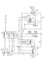
- FIG. 1 is a diagram illustrating an overall configuration of a forklift according to the present embodiment.
- FIG. 2 is a block diagram showing a control system of the forklift shown in FIG.
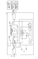
- FIG. 3 is a block diagram illustrating a control example of the traveling hydraulic pump according to the present embodiment that is executed by the control device.
- FIG. 4 is a diagram illustrating a table in which modulation setting values are described and an example of the table.
- FIG. 5 is a flowchart showing a control example of the HST pump executed by the control device provided in the forklift.
- FIG. 6 is a block diagram for explaining the control according to this modification.
- FIG. 7 is a flowchart of control according to this modification.
- FIG. 8 is a diagram for explaining a modification of the control of the HST pump by the control device.
- FIG. 1 is a diagram illustrating an overall configuration of a forklift according to the present embodiment.
- FIG. 2 is a block diagram showing a control system of the forklift shown in FIG.
- the forklift 1 includes a vehicle body 3 having drive wheels 2 a and steering wheels 2 b, and a work machine 5 provided in front of the vehicle body 3.
- the vehicle body 3 is provided with an engine 4 as an internal combustion engine, a variable displacement travel hydraulic pump 10 that drives the engine 4 as a drive source, and a work machine hydraulic pump 16.
- the drive wheel 2 a is driven by the power of the hydraulic motor 20 by connecting the variable displacement traveling hydraulic pump 10 and the variable displacement hydraulic motor 20 through a closed hydraulic circuit.
- the forklift 1 travels by HST.
- the work machine 5 includes a lift cylinder 7 that raises and lowers the fork 6 and a tilt cylinder 8 that tilts the fork 6.
- the driver's seat of the vehicle body 3 is provided with a forward / reverse lever 42a, a brake pedal (inching pedal) 40a, an accelerator pedal 41a, and a work machine operation lever (not shown) including a lift lever and a tilt lever for operating the work machine 5.
- the brake pedal 40a and the accelerator pedal 41a are provided at positions where the operator of the forklift 1 can perform a stepping operation from the driver's seat. In FIG. 1, the brake pedal 40a and the accelerator pedal 41a are depicted in an overlapping state.
- the accelerator pedal 41 a is an accelerator operation unit that performs an operation for increasing or decreasing the amount of fuel supplied to the engine 4.
- the forklift 1 includes a traveling hydraulic pump 10 and a hydraulic motor 20 connected by hydraulic supply conduits 10 a and 10 b of a main hydraulic circuit 100 that is a closed circuit.
- the traveling hydraulic pump 10 (hereinafter referred to as HST pump 10 as appropriate) is a device that is driven by the engine 4 to discharge hydraulic oil.
- the HST pump 10 has, for example, a swash plate 10S, and a variable capacity whose capacity can be changed by changing a tilt angle of the swash plate 10S (hereinafter referred to as a swash plate tilt angle).
- the type of pump is a variable capacity whose capacity can be changed by changing a tilt angle of the swash plate 10S.
- the hydraulic motor 20 (hereinafter referred to as HST motor 20 as appropriate) is driven by hydraulic fluid discharged from the HST pump 10.
- the hydraulic motor 20 is a variable displacement hydraulic motor whose capacity can be changed by changing the swash plate tilt angle, for example.
- the HST motor 20 may be a fixed displacement hydraulic motor.
- the output shaft 20a of the HST motor 20 is connected to the drive wheel 2a via the transfer 20b, and the forklift 1 can be driven by rotating the drive wheel 2a.
- the rotation direction of the HST motor 20 can be switched according to the supply direction of hydraulic oil from the HST pump 10. By switching the rotation direction of the HST motor 20, the forklift 1 can be moved forward or backward.
- the forklift 1 moves forward, and when the hydraulic oil is supplied to the HST motor 20 from the hydraulic pressure supply line 10b. It is assumed that the forklift 1 moves backward.
- the forklift 1 has a pump capacity setting unit 11, a motor capacity setting unit 21, and a charge pump 15.
- the pump capacity setting unit 11 is provided in the HST pump 10.
- the pump capacity setting unit 11 includes a forward pump electromagnetic proportional control valve 12, a reverse pump electromagnetic proportional control valve 13, and a pump capacity control cylinder 14.
- the pump capacity setting unit 11 receives a command signal from a control device 30 described later with respect to the forward pump electromagnetic proportional control valve 12 and the reverse pump electromagnetic proportional control valve 13.
- the capacity of the pump capacity setting unit 11 is changed when the pump capacity control cylinder 14 is operated in accordance with a command signal given from the control device 30 and the swash plate tilt angle of the HST pump 10 is changed.
- the piston 14a In the pump displacement control cylinder 14, the piston 14a is held at the neutral position when the swash plate tilt angle is zero. In this state, the swash plate tilt angle of the HST pump 10 is zero. For this reason, even if the engine 4 rotates, the amount of hydraulic oil discharged from the HST pump 10 to the main hydraulic circuit 100 is zero.
- the pump capacity control is performed from the reverse pump electromagnetic proportional control valve 13 according to the command signal.
- Pump control pressure is applied to the cylinder 14. Then, the piston 14a moves to the right side in FIG.
- the swash plate 10S of the HST pump 10 is tilted in the direction of discharging hydraulic oil to the hydraulic supply line 10b in conjunction with this. To do.
- the moving amount of the piston 14a increases as the pump control pressure supplied from the reverse pump electromagnetic proportional control valve 13 increases, the amount of change in the swash plate tilt angle of the HST pump 10 increases. That is, when a command signal is given from the control device 30 to the reverse pump electromagnetic proportional control valve 13, a pump control pressure corresponding to the command signal is given from the reverse pump electromagnetic proportional control valve 13 to the pump displacement control cylinder 14. It is done.
- the operation of the pump displacement control cylinder 14 causes the swash plate 10S of the HST pump 10 to tilt so that a desired amount of hydraulic oil can be discharged to the hydraulic pressure supply line 10b.
- hydraulic oil is discharged from the HST pump 10 to the hydraulic pressure supply line 10b, and the HST motor 20 rotates in the reverse direction.
- the motor capacity setting unit 21 is provided in the HST motor 20.
- the motor capacity setting unit 21 includes a motor electromagnetic proportional control valve 22, a motor cylinder control valve 23, and a motor capacity control cylinder 24.
- motor control pressure is supplied from the motor electromagnetic proportional control valve 22 to the motor cylinder control valve 23, and the motor The capacity control cylinder 24 operates.
- the motor capacity control cylinder 24 is operated, the swash plate tilt angle of the HST motor 20 changes in conjunction with this. For this reason, the capacity of the HST motor 20 is changed in accordance with a command signal from the control device 30.
- the motor capacity setting unit 21 is configured such that the swash plate tilt angle of the HST motor 20 decreases as the motor control pressure supplied from the motor electromagnetic proportional control valve 22 increases.
- the charge pump 15 is driven by the engine 4.
- the charge pump 15 supplies pump control pressure to the pump displacement control cylinder 14 via the forward pump electromagnetic proportional control valve 12 and the reverse pump electromagnetic proportional control valve 13 described above. Further, the charge pump 15 has a function of supplying a motor control pressure to the motor cylinder control valve 23 via the motor electromagnetic proportional control valve 22.
- the engine 4 drives the work machine hydraulic pump 16 in addition to the HST pump 10.
- the work machine hydraulic pump 16 supplies hydraulic oil to a lift cylinder 7 and a tilt cylinder 8 that are work actuators for driving the work machine 5.
- the work machine hydraulic pump 16 is a variable displacement pump having a swash plate 16S and capable of changing the capacity by changing the swash plate tilt angle of the swash plate 16S.
- the forklift 1 includes a brake potentiometer 40, an accelerator potentiometer 41, a forward / reverse lever switch 42, an engine rotation sensor 43, and a vehicle speed sensor 46.
- the brake potentiometer 40 detects and outputs the operation amount when the brake pedal (inching pedal) 40a is operated.
- the operation amount of the brake pedal 40a is the brake opening degree Bs.
- the brake opening Bs output from the brake potentiometer 40 is input to the control device 30.
- the accelerator potentiometer 41 outputs the operation amount As when the accelerator pedal 41a is operated.
- the operation amount As of the accelerator pedal 41a is also referred to as an accelerator opening degree As.
- the accelerator opening As output from the accelerator potentiometer 41 is input to the control device 30. Since the accelerator potentiometer 41 detects the accelerator opening As, it also functions as an accelerator opening sensor. Opening the accelerator means that the fuel supply amount to the engine 4 is increased by depressing the accelerator pedal 41a. Closing the accelerator means reducing the amount of fuel supplied to the engine 4 by returning the depressed accelerator pedal 41a.
- the forward / reverse lever switch 42 is a selection switch for inputting the traveling direction of the forklift 1.
- a forward / reverse lever switch 42 that can select three traveling directions of forward, neutral, and reverse by operating a forward / reverse lever 42a provided at a position that can be selectively operated from the driver's seat is applied. ing.
- Information indicating the traveling direction selected by the forward / reverse lever switch 42 is given to the control device 30 as selection information.
- the engine rotation sensor 43 detects the actual rotation speed of the engine 4.
- the rotational speed of the engine 4 detected by the engine rotational sensor 43 is the actual engine rotational speed Nr.
- Information indicating the actual engine speed Nr is input to the control device 30.
- the rotational speed of the engine 4 per unit time is the rotational speed of the engine 4.
- the actual engine speed Nr includes the actual rotational speed of the engine 4.
- the control device 30 includes a processing unit 30C and a storage unit 30M.
- the control device 30 is, for example, a computer.
- the processing unit 30C is configured by combining, for example, a CPU (Central Processing Unit) and a memory.
- the processing unit 30C controls the operation of the main hydraulic circuit 100 by reading a computer program stored in the storage unit 30M for controlling the main hydraulic circuit 100 and executing instructions described therein. .
- the storage unit 30M stores the above-described computer program, data necessary for controlling the main hydraulic circuit 100, and the like.
- the storage unit 30M is configured by, for example, a ROM (Read Only Memory), a storage device, or a combination thereof.
- the controller 30 is electrically connected to various sensors such as a brake potentiometer 40, an accelerator potentiometer 41, a forward / reverse lever switch 42, an engine rotation sensor 43, and a vehicle speed sensor 46. Based on the input signals from these various sensors, the control device 30 generates command signals for the forward pump electromagnetic proportional control valve 12 and the reverse pump electromagnetic proportional control valve 13, and generates the generated command signals respectively.
- the electromagnetic proportional control valves 12, 13 and 22 are given.
- the control device 30 obtains the target maximum absorption torque of the HST pump 10 based on the accelerator opening degree As detected by the accelerator potentiometer 41. Then, control device 30 controls HST pump 10 so that the absorption torque of HST pump 10 becomes the calculated target maximum absorption torque. In the control of the HST pump 10, the control device 30 changes the swash plate tilt angle of the HST pump 10 by the pump displacement control cylinder 14, for example.
- FIG. 3 is a block diagram illustrating a control example of the traveling hydraulic pump 10 of the present embodiment that is executed by the control device 30.
- the control device 30 includes an accelerator opening conversion unit 31, a modulation control unit 32, a target maximum absorption torque setting unit 33, and an HST pump electromagnetic proportional control output current conversion unit 34.
- the accelerator opening conversion unit 31 is electrically connected to the output unit of the accelerator potentiometer 41.
- the accelerator potentiometer 41 detects the opening of the accelerator pedal 41a and outputs it as a voltage value.
- the accelerator opening conversion unit 31 converts the voltage value output from the accelerator potentiometer 41 into an accelerator opening As.
- the accelerator opening As is, for example, 0% when the accelerator pedal 41a is not depressed and 100% when the accelerator pedal 41a is completely depressed.
- the modulation control unit 32 includes a modulation calculation unit 32A and a holding unit 32B.
- the modulation calculation unit 32A changes the responsiveness of the HST pump 10 with respect to the operation amount of the accelerator pedal 41a.
- the modulation calculation unit 32A has, for example, an accelerator in a table in which set values (hereinafter, referred to as modulation set values as appropriate) described in advance according to the accelerator opening As and the maximum absorption torque of the HST pump 10 are described.
- the modulation set value is obtained by giving at least one of the accelerator opening As detected by the potentiometer 41 and the maximum absorption torque of the HST pump 10.
- the modulation calculation unit 32A corrects the accelerator opening As detected by the accelerator potentiometer 41 using the obtained set value to obtain a corrected accelerator opening Asc.
- the table in which the modulation setting value is described is stored in the table storage unit 32MP.
- the table storage unit 32MP exists in the storage unit 30M illustrated in FIG.
- the corrected accelerator opening degree Asc obtained in the previous control cycle may be given to the table in which the modulation set value is described. In this case, the corrected accelerator opening degree Asc obtained in the previous control cycle is corrected by the set value obtained from the aforementioned table.
- the modulation calculation unit 32A sets a cutoff frequency f of the accelerator opening degree As, and outputs a value delayed according to the cutoff frequency f as the corrected accelerator opening degree Asc.
- delaying the accelerator opening As according to the set cutoff frequency f is referred to as correction of the accelerator opening As.
- the cut-off frequency f can be obtained by equation (1).
- ⁇ is the time constant of the first-order lag element.
- the input of the modulation calculation unit 32A is an accelerator opening As
- the output is a corrected accelerator opening Asc.
- the relationship between the accelerator opening As that is an input and the corrected accelerator opening Asc that is an output is expressed by Expression (2).
- equation (3) is obtained.
- Ascb in Expression (3) indicates the corrected accelerator opening degree Asc output from the modulation calculating part 32A before the corrected accelerator opening degree Asc, which is the output of the modulation calculating part 32A at the present time.
- Asc + ⁇ ⁇ dAsc / dt As (2)
- Asc + (Asc ⁇ Ascb) ⁇ ⁇ / ⁇ t As (3)
- equation (4) is obtained. From the equation (4), the corrected accelerator opening Asc is calculated as follows: the accelerator opening As input to the modulation calculating section 32A at the present time, and the corrected accelerator opening Ascb output from the modulation calculating section 32A before the current time ⁇ t. It is expressed by the relationship between the time constant ⁇ and the time ⁇ t.
- the time ⁇ t can be a time required for one cycle of control, for example.
- the corrected accelerator opening Ascb can be the corrected accelerator opening Asc output from the modulation calculation unit 32A in the previous control cycle.
- the time constant ⁇ is set in advance.
- the accelerator opening As is the accelerator opening As output from the accelerator opening conversion unit 31 at the present time.
- the modulation calculation unit 32A delays the input accelerator opening As and outputs it as a corrected accelerator opening Asc.
- the degree of delay is set by the cut-off frequency f or the time constant ⁇ .
- the modulation setting value described above is the cutoff frequency f or the time constant ⁇ . Increasing the cut-off frequency f (decreasing the time constant ⁇ ) reduces the degree of delay, and decreasing the cut-off frequency f (increasing the time constant ⁇ ) increases the degree of delay.
- the modulation calculation unit 32A can change the response of the HST pump 10 to the operation of the accelerator pedal 41a (hereinafter, appropriately referred to as accelerator response) by changing the degree of delay of the input accelerator opening As. .
- FIG. 4 is a diagram illustrating an example of the table TBd and the table TBi in which modulation setting values are described.
- two types of tables TBd and TBi are stored in the table storage unit 32MP.
- a cutoff frequency f is described as a modulation setting value.
- the table TBd is used when the accelerator is closed, that is, when the accelerator opening As is decreased.
- the table TBi is used when the accelerator is opened, that is, when the accelerator opening As is increased.
- the table TBd is appropriately referred to as a first table TBd
- the table TBi is appropriately referred to as a second table TBi.
- the modulation calculating unit 32A obtains a modulation set value, that is, a cutoff frequency f using the first table TBd.
- the modulation calculation unit 32A obtains the corrected accelerator opening degree Asc using the cut-off frequency f obtained using the first table TBd.
- the modulation calculation unit 32A obtains the cutoff frequency f using the second table TBi.
- the modulation calculation unit 32A obtains the corrected accelerator opening degree Asc using the cut-off frequency f obtained using the second table TBi.
- a cutoff frequency f is determined based on the corrected accelerator opening degree Asc and the maximum absorption torque Tm.
- the number surrounded by the corrected accelerator opening Asc and the maximum absorption torque Tm is the cutoff frequency f.
- the corrected accelerator opening degree Asc increases as the number assigned to the corrected accelerator opening degree Asc increases. In this example, the corrected accelerator opening Asc0 is 0%, and the corrected accelerator opening Asc9 is 100%. As the number assigned to the maximum absorption torque Tm increases, the maximum absorption torque Tm increases.
- the cutoff frequency f described in the first table TBd increases as the maximum absorption torque Tm decreases, and decreases as the corrected accelerator opening Asc decreases.
- the cutoff frequency f may be constant regardless of the corrected accelerator opening degree Asc.
- the cut-off frequency f has a decreasing rate of the corrected accelerator opening Asc that increases as the maximum absorption torque Tm decreases, and a decreasing rate of the corrected accelerator opening Asc that decreases as the corrected accelerator opening Asc decreases. It is determined to be low.
- the cutoff frequency f is determined based on the accelerator opening degree As.
- the accelerator opening As increases as the number assigned to the accelerator opening As increases.
- the accelerator opening As0 is 0% and the accelerator opening As7 is 100%.
- the cutoff frequency f described in the second table TBi has a portion that decreases as the accelerator opening As increases. That is, the cut-off frequency f decreases as the accelerator opening As increases from the accelerator opening As0 to the accelerator opening As6, but the cut-off frequency f of the accelerator opening As7 is slightly higher than the accelerator opening As6. It is getting bigger.
- the cut-off frequency f of the second table TBi is determined such that the accelerator responsiveness decreases as the accelerator opening As increases when the accelerator opening As is less than 100%.
- the modulation calculating unit 32A adds the corrected accelerator opening Asc output from the modulation calculating unit 32A in the previous control cycle and the target maximum absorption described later in the first table TBd shown in FIG.
- the maximum absorption torque Tm output from the torque setting unit 33 that is, the target maximum absorption torque Tmp is given, and the corresponding cutoff frequency f is obtained.
- the modulation calculating unit 32A can hold the corrected accelerator opening degree Asc of the previous control cycle until the current control cycle.
- the accelerator opening As detected by the accelerator potentiometer 41 in the current control cycle is determined by the cutoff frequency f obtained from the corrected accelerator opening Asc of the previous control cycle and the target maximum absorption torque Tmp. It is corrected. In this case, it is sufficient that the corrected accelerator opening degree Asc of the previous control cycle is used, and the target maximum absorption torque Tmp may be the value of the previous control cycle or the value of the current control cycle. Also good. In the present embodiment, the target maximum absorption torque Tmp of the current control cycle is used.
- the modulation calculation unit 32A outputs the corrected accelerator opening As as the corrected accelerator opening Asc of the current control cycle.
- the cutoff frequency f is 0.50
- the maximum accelerator torque Tm5 is the corrected accelerator opening Asc6
- the off frequency f is 0.30.
- the modulation calculation unit 32A obtains the corrected accelerator opening Asc by giving the calculated cutoff frequency f and the accelerator opening As detected by the accelerator potentiometer 41 to the above-described equation (5).
- the cut-off frequency f may be obtained using the target swash plate tilt angle or the vehicle speed instead of the target maximum absorption torque Tmp.
- the modulation calculation unit 32A gives the accelerator opening As detected by the accelerator potentiometer 41 to the second table TBi shown in FIG. 4 to obtain the corresponding cutoff frequency f.
- the cutoff frequency f at the accelerator opening As4 is 0.20
- the cutoff frequency f at the accelerator opening As2 is 0.30.
- the modulation calculation unit 32A obtains the corrected accelerator opening Asc by giving the calculated cutoff frequency f and the accelerator opening As detected by the accelerator potentiometer 41 to the above-described equation (5).
- the holding unit 32B includes a determination unit 35, a large selection unit 36, and a switching unit 37.
- the determination unit 35 receives an accelerator opening As from the accelerator opening conversion unit 31 and a target maximum absorption torque Tmp output from a target maximum absorption torque setting unit 33 described later.
- the large selection unit 36 receives the target maximum absorption torque Tmp output from the target maximum absorption torque setting unit 33 described later and the output of the switching unit 37.
- the switching unit 37 switches the output of the large selection unit 36 and the minimum absorption torque Tmin as a value to be input to the large selection unit 36.
- the minimum absorption torque Tmin is 0 in the present embodiment, but is not limited to this. With such a structure, the determination unit 35 switches the switching unit 37 to the output side or the minimum output side of the large selection unit 36 based on the accelerator opening As.
- the holding unit 32B gives the corrected target maximum absorption torque Tmp to the modulation calculating unit 32A.
- the holding unit 32B holds the corrected target maximum absorption torque Tmp given to the modulation calculating unit 32A at the timing value at which the accelerator potentiometer 41 detects a decrease in the accelerator opening As.
- the determination unit 35 controls the switching unit 37 so that the output of the large selection unit 36 is input to the large selection unit 36 when the accelerator potentiometer 41 detects a decrease in the accelerator opening degree As.
- the determination unit 35 sets the switching unit 37 so that the output of the large selection unit 36 is input to the large selection unit 36. You may control.
- the maximum absorption torque at the timing when the accelerator potentiometer 41 detects a decrease in the accelerator opening As (the target maximum absorption torque obtained by the target maximum absorption torque setting unit 33 described later). Tmp) and the maximum absorption torque after that timing are compared.
- the target maximum absorption torque Tmp obtained by the target maximum absorption torque setting unit 33 described later decreases from the previous value.
- the determination unit 35 controls the switching unit 37 so that the minimum absorption torque Tmin is input to the large selection unit 36.
- the large selection unit 36 compares the target maximum absorption torque Tmp obtained by the target maximum absorption torque setting unit 33 described later with the minimum absorption torque Tmin. Since the minimum absorption torque Tmin is 0, the large selection unit 36 outputs the input value of the large selection unit 36, that is, the target maximum absorption torque Tmp obtained by the target maximum absorption torque setting unit 33 described later.
- the holding unit 32B cancels the holding of the value of the maximum absorption torque at the timing when the decrease in the accelerator opening As is detected.
- the target maximum absorption torque setting unit 33 calculates a target maximum absorption torque Tmp according to the corrected accelerator opening degree Asc calculated by the modulation calculation unit 32A.
- the control cycle in which the modulation calculation unit 32A obtains the corrected accelerator opening degree Asc and the control cycle in which the target maximum absorption torque setting unit 33 obtains the maximum target absorption torque Tmp using the corrected accelerator opening degree Asc are the same.
- the target maximum absorption torque setting unit 33 has a data table 33TB in which the relationship between the accelerator opening As and the target maximum absorption torque Tmp is described, for example, as indicated by the characteristic line L1.
- the relationship between the accelerator opening As and the target maximum absorption torque Tmp is determined, for example, so that the fuel consumption rate of the engine 4 shown in FIG. 2 is minimized.
- the target maximum absorption torque setting unit 33 can obtain the target maximum absorption torque Tmp corresponding to the corrected accelerator opening degree Asc by giving the corrected accelerator opening degree Asc obtained by the modulation calculating unit 32A to the data table 33TB.
- the target maximum absorption torque setting unit 33 outputs the obtained target maximum absorption torque Tmp to the HST pump electromagnetic proportional control output current conversion unit 34.
- the HST pump electromagnetic proportional control output current conversion unit 34 as an output control unit generates a target absorption torque command Ic based on the target maximum absorption torque Tmp and outputs it to the pump capacity setting unit 11 of the HST pump 10.
- the pump capacity setting unit 11 controls the swash plate tilt angle of the HST pump 10 so that the torque absorbed by the HST pump 10 becomes the target maximum absorption torque Tmp.
- the target absorption torque command Ic is a signal (current value in this embodiment) for causing the torque absorbed by the HST pump 10 to be the target maximum absorption torque Tmp.
- the target absorption torque command Ic is output from the HST pump electromagnetic proportional control output current converter 34 to the forward pump electromagnetic proportional control valve 12 or the reverse pump electromagnetic proportional control valve 13 of the pump capacity setting unit 11.
- FIG. 5 is a flowchart showing a control example of the HST pump 10 executed by the control device 30 provided in the forklift 1.
- the control device 30 shown in FIG. 3 repeats a series of processes from step S11 to step S17 in the flowchart shown in FIG. 5 at a predetermined cycle (for example, time ⁇ t).
- a predetermined cycle for example, time ⁇ t.
- the series of processes described above is appropriately referred to as one control cycle.
- the modulation control unit 32 of the control device 30 In controlling the HST pump 10, the modulation control unit 32 of the control device 30, in this control example, the modulation calculation unit 32 ⁇ / b> A acquires the accelerator opening As from the accelerator potentiometer 41 and the accelerator opening conversion unit 31. In step S11, the modulation calculation unit 32A compares the accelerator opening As acquired in the current control with the corrected accelerator opening Asc in the previous control, that is, the control one cycle before.
- step S12 when the accelerator opening As is equal to or smaller than the corrected accelerator opening Asc (As ⁇ Asc), the modulation calculation unit 32A does not increase the accelerator opening, that is, the accelerator pedal 41a is closed or held. It determines with having been carried out (step S12, Yes). In this case, in step S13, the modulation calculation unit 32A selects the first table TBd shown in FIG. 4 in order to obtain the corrected accelerator opening degree Asc.
- step S12 when the accelerator opening As is larger than the corrected accelerator opening Asc (As> Asc), the modulation calculating unit 32A determines that the accelerator opening has increased, that is, the accelerator pedal 41a has been depressed (step S12). , No). In this case, in step S14, the modulation calculating unit 32A selects the second table TBi shown in FIG. 4 in order to obtain the corrected accelerator opening degree Asc.
- step S15 When the table for obtaining the corrected accelerator opening degree Asc is selected, the process proceeds to step S15.
- the accelerator pedal 41a is closed or held, the first table TBd is selected.
- the modulation calculation unit 32A gives the corrected accelerator opening Asc of the previous control cycle and the maximum absorption torque input from the large selection unit 36 shown in FIG. 3 to the first table TBd.
- the large selection unit 36 As long as the output of the large selection unit 36 is input to the large selection unit 36 from the switching unit 37 shown in FIG. 3, that is, as long as the accelerator pedal 41a is closed or being closed, the large selection unit 36
- the target maximum absorption torque Tmp output from the target maximum absorption torque setting unit 33 is output at the timing when the accelerator potentiometer 41 detects a decrease in the accelerator opening As.
- the maximum absorption torque given to the first table TBd is the target maximum absorption torque setting unit at the timing when the accelerator potentiometer 41 detects a decrease in the accelerator opening As. This is the target maximum absorption torque Tmp output from 33.
- the modulation calculation unit 32A obtains the cutoff frequency f corresponding to the corrected accelerator opening degree Asc and the maximum absorption torque given thereto from the first table TBd. Then, the modulation calculation unit 32A uses the acquired cut-off frequency f to obtain a corrected accelerator opening degree Asc corresponding to a state where the accelerator pedal 41a is closed or is being closed.
- the second table TBi is selected.
- the modulation calculation unit 32A gives the accelerator opening As of the current control to the second table TBi. Since the accelerator pedal 41a is depressed, the determination unit 35 of the holding unit 32B illustrated in FIG. 3 switches the switching unit 37 so that the minimum absorption torque Tmin is input to the large selection unit 36.
- the modulation calculation unit 32A acquires the cutoff frequency f corresponding to the accelerator opening degree As given to the second table TBi. And the modulation
- step S16 the target maximum absorption torque setting unit 33 of the control device 30 shown in FIG. 3 gives the corrected accelerator opening degree Asc obtained by the modulation calculation unit 32A to the data table 33TB, and obtains the corresponding target maximum absorption torque Tmp. 3 is output to the HST pump electromagnetic proportional control output current converter 34 shown in FIG.
- the HST pump electromagnetic proportional control output current conversion unit 34 generates a target absorption torque command Ic based on the target maximum absorption torque Tmp input from the target maximum absorption torque setting unit 33, Output to the pump capacity setting unit 11 of the HST pump 10.
- the pump capacity setting unit 11 controls the swash plate tilt angle of the HST pump 10 based on the inputted target absorption torque command Ic so that the torque absorbed by the HST pump 10 becomes the target maximum absorption torque Tmp.
- step S11 When the control device 30 executes step S11 to step S17, one cycle of control is completed. When one cycle of control ends, the control device 30 returns to step S11 and executes control of the next cycle.
- the control device 30 causes the target maximum absorption by the above-described control.
- the changing speed of the torque Tmp in this case, the decreasing speed can be increased.
- the forklift 1 increases the degree of deceleration from when the accelerator pedal 41a is released until it stops. That is, the deceleration force increases rapidly after the accelerator pedal 41a is released.
- the operator can easily realize the positioning of the forklift 1 only by operating the accelerator pedal 41a.
- the forklift 1 equipped with HST is difficult to move slightly because it cannot creep, but according to the present embodiment, even when positioning by a minute movement of several centimeters is necessary during low-speed traveling. The operator can easily achieve positioning.
- the maximum absorption torque Tm given to the first table TBd is held at the target maximum absorption torque Tmp at the timing described above.
- the moment when the operator releases the accelerator pedal 41a is the timing when the accelerator opening As decreases or when the absorption torque of the HST pump 10 starts to decrease.
- the modulation calculation unit 32A determines the cutoff frequency f based on the corrected accelerator opening degree Asc of the previous control cycle based on the held target maximum absorption torque Tmp.
- the cut-off frequency f decreases as the corrected accelerator opening Asc decreases. Further, the cut-off frequency f decreases as the maximum absorption torque increases. Further, when the cut-off frequency f is small, the change speed of the target maximum absorption torque Tmp is small.
- the control device 30 causes the target maximum absorption by the above-described control.
- the changing speed of the torque Tmp in this case, the decreasing speed can be reduced.
- the forklift 1 can reduce the possibility of collapsing because the degree of deceleration is weakened until it stops.
- the uncomfortable feeling experienced by the operator can be reduced.
- the forklift 1 is equipped with HST, since the control of the HST pump 10 by this embodiment is performed, there exists an advantage that even the operator who is accustomed to the operation of the forklift provided with the torque converter does not receive an uncomfortable feeling.
- the target maximum absorption torque setting unit 33 determines the target maximum absorption torque Tmp.
- target maximum absorption torque is merely one concept, and this can be expressed as, for example, a target swash plate tilt angle.
- the target swash plate tilt angle is a target tilt angle of the swash plate 10S included in the HST pump 10 shown in FIG.
- FIG. 6 is a block diagram for explaining the control according to this modification.
- FIG. 7 is a flowchart of control according to this modification.
- the operator of the forklift 1 shown in FIG. 1 depresses the accelerator pedal 41a shown in FIG. 2, the slack of acceleration when the degree of opening of the accelerator pedal 41a is medium is suppressed.
- the modulation calculation unit 32A shown in FIG. 6 gives the accelerator opening degree As to the second table TBi shown in FIGS.
- the obtained first cut-off frequency fn is obtained.
- the modulation calculation unit 32A gives the second accelerator frequency Asb obtained at the timing before the first cut-off frequency fn is obtained to the second table TBi to obtain the second cut-off frequency fb obtained.
- the timing before the first cut-off frequency fn is obtained is the control one cycle before the period in which the first cut-off frequency fn is obtained.
- the modulation calculation unit 32A corrects the accelerator opening As detected by the accelerator potentiometer 41 using the larger one of the first cut-off frequency fn and the second cut-off frequency fb to obtain the corrected accelerator opening Asc.
- the modulation calculation unit 32A includes a first set value generation unit 32ACn, a second set value generation unit 32ACb, a large selection unit 32As, and a corrected accelerator opening generation unit 32AT.
- a detection value of the accelerator potentiometer 41 is input to the first set value generation unit 32ACn via the accelerator opening conversion unit 31. That is, the accelerator opening degree As is input to the first set value generation unit 32ACn.
- the first set value generation unit 32ACn gives the input accelerator opening degree As to the second table TBi, acquires the corresponding first cut-off frequency fn, and makes a large selection. To the unit 32As.
- the output of the modulation operation unit 32A is input to the second set value generation unit 32ACb. That is, the corrected accelerator opening degree Asc in the previous control cycle is input to the second set value generation unit 32ACb.
- the second set value generation unit 32ACb gives the input corrected accelerator opening degree Asc to the second table TBi, acquires the corresponding second cutoff frequency fb, and sends it to the large selection unit 32As. Output.
- step S142 the large selection unit 32As compares the input first cutoff frequency fn with the second cutoff frequency fb, and outputs the larger one.
- step S143 the corrected accelerator opening generation unit 32AT gives the value input from the large selection unit 32As and the accelerator opening As from the accelerator potentiometer 41 to the above-described equation (5) to correct the accelerator in the current control cycle. An opening degree Asc is generated and output.
- the second table TBi shows that the cutoff frequency fs decreases from a high state as the accelerator opening As increases, the accelerator opening As is medium, and the cutoff frequency f is a minimum value. Become. Thereafter, the cutoff frequency increases as the accelerator opening As increases.
- the second table TBi has the highest cutoff frequency f when the accelerator opening As is the minimum (As0) and the maximum (As7). For this reason, the second table TBi is determined such that when the accelerator opening As increases, the accelerator responsiveness decreases again after the accelerator opening As decreases, and then the accelerator responsiveness increases again.
- the cutoff frequency f decreases as the accelerator opening As increases. For this reason, when the operator depresses the accelerator pedal 41a moderately, the cut-off frequency f decreases according to the accelerator opening degree As, so that the change speed of the target maximum absorption torque Tmp also decreases. As a result, the operator may feel slack when the forklift 1 starts.
- the cut-off frequency f is determined using the second table TBi.
- the second cut-off frequency fb determined by the corrected accelerator opening degree Asc of the previous control cycle and the current control cycle are determined.
- the larger one of the first cutoff frequency fn determined by the accelerator opening degree As is used.
- the corrected accelerator opening Asc changes according to the temporary delay of the accelerator opening As. For this reason, when the accelerator pedal 41a is depressed, the corrected accelerator opening Asc in the previous control cycle becomes smaller than the accelerator opening As in the current control cycle.
- the second cut-off frequency fb becomes larger than the first cut-off frequency fn.
- the cutoff frequency f is 0.20 from the second table TBi shown in FIG. If the corrected accelerator opening in the previous control cycle is the value of As1, the cutoff frequency f obtained from the corrected accelerator opening Asc is 3.00. In the present modification, since the larger one of the two cutoff frequencies f is used to generate the corrected accelerator opening degree Asc in the current control cycle, 3.00 is selected as the cutoff frequency f. By using this cutoff frequency f, the change speed of the target maximum absorption torque Tmp is maintained in a large state, so that the forklift 1 starts quickly.
- the cut-off frequency f obtained from the corrected accelerator opening Asc becomes 0.30.
- This cut-off frequency f is as low as 0.30 even if the larger cut-off frequency f is selected from 0.20 of the cut-off frequency f obtained from the accelerator opening As in the current control cycle.
- the cut-off frequency f is selected to be as large as 20, so that the forklift 1 can be quickly operated as intended by the operator. You can start and accelerate.
- the corrected accelerator opening generation unit 32AT generates the corrected accelerator opening Asc using the larger cutoff frequency f selected by the large selection unit 32As, so that the change rate of the target maximum absorption torque Tmp is changed. The decrease is suppressed. As a result, the start of the forklift 1 received by the operator is reduced. Moreover, since the cut-off frequency f becomes a small value after the forklift 1 has started, unnecessary jumping out of the forklift 1 after starting is suppressed.
- the cut-off frequency f of the second table TBi is a relatively large value, so that responsiveness to the operation of the accelerator pedal 41a when the forklift 1 moves at a slow speed can be ensured. Furthermore, when the accelerator pedal 41a is stepped on until the accelerator opening As reaches the maximum, the forklift 1 can start quickly and accelerate as intended by the operator.
- FIG. 8 is a diagram for explaining a modification of the control of the HST pump 10 by the control device 30.
- the cut-off frequency f is determined according to the maximum absorption torque Tm and the accelerator opening degree As, but the vehicle speed Vc of the forklift 1 may be used instead of the maximum absorption torque Tm. This is because the maximum absorption torque Tm and the vehicle speed Vc are normally in a proportional relationship.
- the cut-off frequency f is determined according to the vehicle speed Vc of the forklift 1 instead of the maximum absorption torque Tm.
- the cut-off frequency f increases as the vehicle speed Vc decreases. That is, the cut-off frequency f is set so that the accelerator responsiveness increases as the vehicle speed Vc decreases.
- the vehicle speed Vc of the forklift 1 detected by the vehicle speed sensor 46 is input to the modulation calculation unit 32A and the large selection unit 36 as shown in FIG. Further, the accelerator opening As from the accelerator potentiometer 41 is input to the determination unit 35a via the accelerator opening conversion unit 31a.
- Other configurations are the same as the case where the maximum absorption torque Tm is used.
- a first table TBd based on the maximum absorption torque Tm and a first table TBd based on the vehicle speed Vc are prepared, and the control device 30 sets the corrected accelerator opening degree Asc using any one of the first tables TBd.
- Ask For example, if the maximum absorption torque Tm or the vehicle speed Vc cannot be obtained due to some cause such as disconnection of the in-vehicle signal line of the forklift 1, the control device 30 uses the information obtained normally to calculate the corrected accelerator opening Asc. You may make it ask. In this way, reliability is improved.
- the forklift 1 and its control device 30 use the cutoff frequency f that is predetermined according to the change in the accelerator opening As and the maximum absorption torque Tm of the HST pump 10 or the vehicle speed Vc of the forklift 1. Then, the target maximum absorption torque Tmp of the HST pump 10 is obtained. By doing in this way, the forklift 1 and its control device 30 increase the deceleration force when the operator releases the accelerator pedal 41a only when the forklift 1 is traveling in a low speed range, and only the operation of the accelerator pedal 41a. Can be positioned.
- the forklift 1 and its control device 30 can relatively reduce the cutoff frequency f when the traveling speed of the forklift 1 is relatively high, so that the change speed of the target maximum absorption torque Tmp is reduced. be able to.
- the degree of deceleration until the forklift 1 stops can be weakened, the possibility of cargo collapse can be reduced.
- the forklift 1 is restrained from suddenly increasing the deceleration immediately before stopping, the uncomfortable feeling experienced by the operator can be reduced.
Landscapes
- Engineering & Computer Science (AREA)
- Transportation (AREA)
- Structural Engineering (AREA)
- Mechanical Engineering (AREA)
- Civil Engineering (AREA)
- Combustion & Propulsion (AREA)
- Chemical & Material Sciences (AREA)
- Life Sciences & Earth Sciences (AREA)
- Geology (AREA)
- General Engineering & Computer Science (AREA)
- Forklifts And Lifting Vehicles (AREA)
- Control Of Fluid Gearings (AREA)
- Motor Power Transmission Devices (AREA)
- Electric Propulsion And Braking For Vehicles (AREA)
- Reciprocating Pumps (AREA)
Abstract
Description
前記第2の設定値は、前記アクセル開度が増加する場合において、前記アクセル開度が大きくなるにしたがって、前記応答性が低下した後、再び高くなるように定められることが好ましい。
図1は、本実施形態に係るフォークリフトの全体構成を示す図である。図2は、図1に示したフォークリフトの制御系統を示すブロック図である。フォークリフト1は、駆動輪2a及び操向輪2bを有した車体3と、車体3の前方に設けられる作業機5とを有する。車体3には、内燃機関としてのエンジン4、エンジン4を駆動源として駆動する可変容量型の走行用油圧ポンプ10及び作業機油圧ポンプ16が設けられる。駆動輪2aは、可変容量型の走行用油圧ポンプ10と可変容量型の油圧モータ20とを閉じた油圧回路で連通させ、油圧モータ20の動力で駆動される。このように、フォークリフト1は、HSTによって走行する。
図2に示すように、フォークリフト1は、閉回路となる主油圧回路100の油圧供給管路10a、10bによって接続された走行用油圧ポンプ10及び油圧モータ20を備えている。走行用油圧ポンプ10(以下、適宜HSTポンプ10という)は、エンジン4によって駆動されて作動油を吐出する装置である。本実施形態において、HSTポンプ10は、例えば、斜板10Sを有し、斜板10Sの傾転角(以下、斜板傾転角という)を変更することによって容量を変更することのできる可変容量型のポンプである。
図3は、制御装置30が実行する本実施形態の走行用油圧ポンプ10の制御例を示すブロック図である。図3に示すように、制御装置30は、アクセル開度変換部31と、モジュレーション制御部32と、目標最大吸収トルク設定部33と、HSTポンプ電磁比例制御出力電流変換部34とを含む。
モジュレーション制御部32は、モジュレーション演算部32Aと、保持部32Bとを有する。モジュレーション演算部32Aは、アクセルペダル41aの操作量に対するHSTポンプ10の応答性を変化させる。このために、モジュレーション演算部32Aは、アクセル開度As及びHSTポンプ10の最大吸収トルクに応じて予め求められた設定値(以下、適宜モジュレーション設定値という)が記述されたテーブルに、例えば、アクセルポテンショメータ41が検出したアクセル開度As及びHSTポンプ10の最大吸収トルクの少なくとも一方を与えてモジュレーション設定値を求める。そして、モジュレーション演算部32Aは、得られた設定値を用いてアクセルポテンショメータ41が検出したアクセル開度Asを補正して補正アクセル開度Ascを求める。モジュレーション設定値が記述されたテーブルは、テーブル記憶部32MPに記憶されている。テーブル記憶部32MPは、図2に示す記憶部30M内に存在する。モジュレーション設定値が記述されたテーブルには、前回の制御周期で得られた補正アクセル開度Ascが与えられてもよい。この場合、前回の制御周期で得られた補正アクセル開度Ascが、前述したテーブルから得られた設定値によって補正される。
補正アクセル開度Ascを求めるにあたり、モジュレーション演算部32Aは、アクセル開度Asのカットオフ周波数fを設定し、このカットオフ周波数fに応じて遅延した値を補正アクセル開度Ascとして出力する。本実施形態において、設定されたカットオフ周波数fに応じて、アクセル開度Asを遅延させることを、アクセル開度Asの補正という。カットオフ周波数fは、式(1)によって求めることができる。τは、一次遅れ要素の時定数である。式(1)から分かるように、カットオフ周波数fは、時定数τの逆数である。
f=1/(2×π×τ)・・・(1)
Asc+τ×dAsc/dt=As・・・(2)
Asc+(Asc-Ascb)×τ/Δt=As・・・(3)
Asc=As×Δt/(Δt+τ)+Ascb×τ/(Δt+τ)・・・(4)
Asc=As×2×π×f×Δt/(2×π×f×Δt+1)+Ascb/(2×π×f×Δt+1)・・・(5)
図4は、モジュレーション設定値が記述されたテーブルTBd及びテーブルTBiの一例を示す図である。本実施形態において、テーブル記憶部32MPには、2種類のテーブルTBd及びテーブルTBiが記憶されている。テーブルTBd及びテーブルTBiは、いずれも、モジュレーション設定値として、カットオフ周波数fが記述されている。テーブルTBdは、アクセルを閉じるとき、すなわちアクセル開度Asが減少するときに用いられる。テーブルTBiは、アクセルを開くとき、すなわちアクセル開度Asが増加するときに用いられる。以下において、テーブルTBdを適宜第1のテーブルTBdと称し、テーブルTBiを適宜第2のテーブルTBiと称する。
アクセル開度Asが減少した場合、モジュレーション演算部32Aは、図4に示す第1のテーブルTBdに、前回の制御周期においてモジュレーション演算部32Aから出力された補正アクセル開度Asc及び後述する目標最大吸収トルク設定部33から出力される最大吸収トルクTm、すなわち目標最大吸収トルクTmpを与えて、対応するカットオフ周波数fを得る。このため、モジュレーション演算部32Aは、前回の制御周期の補正アクセル開度Ascを、今回の制御周期まで保持することができるようになっている。本実施形態において、前回の制御周期の補正アクセル開度Ascと、目標最大吸収トルクTmpとから求められたカットオフ周波数fによって、今回の制御周期においてアクセルポテンショメータ41によって検出されたアクセル開度Asが補正される。この場合、前回の制御周期の補正アクセル開度Ascが用いられていればよく、目標最大吸収トルクTmpは、前回の制御周期の値であってもよいし、今回の制御周期の値であってもよい。本実施形態では今回の制御周期の目標最大吸収トルクTmpが用いられる。モジュレーション演算部32Aは、補正されたアクセル開度Asを、今回の制御周期の補正アクセル開度Ascとして出力する。
アクセル開度Asが増加した場合、モジュレーション演算部32Aは、図4に示す第2のテーブルTBiに、アクセルポテンショメータ41が検出したアクセル開度Asを与えて、対応するカットオフ周波数fを得る。例えば、アクセル開度As4のときのカットオフ周波数fは0.20、アクセル開度As2のときのカットオフ周波数fは0.30となる。モジュレーション演算部32Aは、求めたカットオフ周波数f及びアクセルポテンショメータ41が検出したアクセル開度Asを前述した式(5)に与えて、補正アクセル開度Ascを求める。
保持部32Bは、判定部35と、大選択部36と、切替部37とを含む。判定部35には、アクセル開度変換部31からアクセル開度Asが入力され、後述する目標最大吸収トルク設定部33から出力された目標最大吸収トルクTmpが入力される。大選択部36には、後述する目標最大吸収トルク設定部33から出力される目標最大吸収トルクTmpと、切替部37の出力とが入力される。切替部37は、大選択部36に入力する値として、大選択部36の出力と、最小吸収トルクTminとを切り替える。最小吸収トルクTminは、本実施形態においては0であるが、これに限定されるものではない。このような構造により、判定部35は、アクセル開度Asに基づいて切替部37を大選択部36の出力側又は最小出力側に切り替える。
目標最大吸収トルク設定部33は、モジュレーション演算部32Aによって求められた補正アクセル開度Ascに応じて、目標最大吸収トルクTmpを求める。モジュレーション演算部32Aが補正アクセル開度Ascを求める制御周期と、その補正アクセル開度Ascを用いて、目標最大吸収トルク設定部33が最大目標吸収トルクTmpを求める制御周期とは同一である。目標最大吸収トルク設定部33は、例えば、特性線L1で示されるような、アクセル開度Asと目標最大吸収トルクTmpとの関係が記述されたデータテーブル33TBを有している。このアクセル開度Asと目標最大吸収トルクTmpとの関係は、例えば、図2に示すエンジン4の燃料消費率が最小になるように定められる。目標最大吸収トルク設定部33は、モジュレーション演算部32Aによって求められた補正アクセル開度Ascをデータテーブル33TBに与えることにより、補正アクセル開度Ascに対応した目標最大吸収トルクTmpを求めることができる。目標最大吸収トルク設定部33は、求めた目標最大吸収トルクTmpを、HSTポンプ電磁比例制御出力電流変換部34に出力する。
図5は、フォークリフト1が備える制御装置30が実行するHSTポンプ10の制御例を示すフローチャートである。図3に示す制御装置30は、HSTポンプ10を制御するにあたって、図5に示すフローチャートのステップS11からステップS17までの一連の処理を、所定の周期(例えば時間Δt)で繰り返す。前述した一連の処理を、適宜、制御の1周期という。
図6は、本変形例に係る制御を説明するためのブロック図である。図7は、本変形例に係る制御のフローチャートである。本変形例は、図1に示すフォークリフト1のオペレータが、図2に示すアクセルペダル41aを踏み込んだときにおいて、アクセルペダル41aの開度が中程度における加速のもたつきを抑制するものである。
図8は、制御装置30によるHSTポンプ10の制御の変形例を説明するための図である。前述した実施形態では、最大吸収トルクTmとアクセル開度Asとに応じてカットオフ周波数fが定められていたが、最大吸収トルクTmの代わりにフォークリフト1の車速Vcを用いてもよい。通常、最大吸収トルクTmと車速Vcとは比例関係にあるからである。この場合、図4に示す第1のテーブルTBdは、最大吸収トルクTmの代わりに、フォークリフト1の車速Vcに応じてカットオフ周波数fが定められる。本変形例では、車速Vcが小さくなるにしたがって、カットオフ周波数fは大きくなる。すなわち、車速Vcが小さくなるにしたがってアクセル応答性が高くなるようにカットオフ周波数fが設定される。
2a 駆動輪
4 エンジン
5 作業機
6 フォーク
10 走行用油圧ポンプ(HSTポンプ)
11 ポンプ容量設定ユニット
12 前進用ポンプ電磁比例制御バルブ
13 後進用ポンプ電磁比例制御バルブ
14 ポンプ容量制御シリンダ
20 油圧モータ(HSTモータ)
30 制御装置
31 アクセル開度変換部
32 モジュレーション制御部
32A モジュレーション演算部
32B 保持部
32MP テーブル記憶部
33 目標最大吸収トルク設定部
34 HSTポンプ電磁比例制御出力電流変換部
35 判定部
36 大選択部
37 切替部
40 ブレーキポテンショメータ
40a ブレーキペダル
41 アクセルポテンショメータ
41a アクセルペダル
46 車速センサ
100 主油圧回路
As アクセル開度
Asc、Ascb 補正アクセル開度
f カットオフ周波数
Tmp 目標最大吸収トルク
τ 時定数
Claims (20)
- エンジンによって駆動される可変容量型の走行用油圧ポンプ、前記走行用油圧ポンプとの間で閉回路を形成し、前記走行用油圧ポンプから吐出された作動油によって駆動される油圧モータ及び前記油圧モータによって駆動される駆動輪を備えるフォークリフトであり、
前記エンジンへの燃料供給量を増減するための操作をするアクセル操作部と、
前記アクセル操作部の操作量であるアクセル開度を検出するアクセル開度センサと、
前記アクセル開度のカットオフ周波数又は時定数の設定値に応じて遅延した値を補正アクセル開度として求めるモジュレーション制御部及び前記補正アクセル開度に応じて前記走行用油圧ポンプの目標最大吸収トルク又は前記走行用油圧ポンプが有する斜板の目標斜板傾転角を求める目標最大吸収トルク設定部を有し、前記走行用油圧ポンプを制御する制御装置と、を含み、
前記モジュレーション制御部は、
少なくとも前記補正アクセル開度に応じたカットオフ周波数又は時定数の設定値が記述されたテーブルを参照して、前回の制御周期で得られた補正アクセル開度により前記設定値を求め、得られた前記設定値を用いて前記アクセル開度センサが検出した前記アクセル開度を補正して今回の制御周期の補正アクセル開度を求め、
前記目標最大吸収トルク設定部は、前記今回の制御周期の補正アクセル開度に応じて前記目標最大吸収トルク又は前記目標斜板傾転角を求める、フォークリフト。 - エンジンによって駆動される可変容量型の走行用油圧ポンプ、前記走行用油圧ポンプとの間で閉回路を形成し、前記走行用油圧ポンプから吐出された作動油によって駆動される油圧モータ及び前記油圧モータによって駆動される駆動輪を備えるフォークリフトであり、
前記エンジンへの燃料供給量を増減するための操作をするアクセル操作部と、
前記アクセル操作部の操作量であるアクセル開度を検出するアクセル開度センサと、
前記アクセル開度のカットオフ周波数又は時定数の設定値に応じて遅延した値を補正アクセル開度として求めるモジュレーション制御部及び前記補正アクセル開度に応じて前記走行用油圧ポンプの目標最大吸収トルク又は前記走行用油圧ポンプが有する斜板の目標斜板傾転角を求める目標最大吸収トルク設定部を有し、前記走行用油圧ポンプを制御する制御装置と、を含み、
前記モジュレーション制御部は、
前記補正アクセル開度と、前記走行用油圧ポンプの目標最大吸収トルク、前記斜板の目標斜板傾転角又は前記フォークリフトの車速とに応じたカットオフ周波数又は時定数の設定値が記述されたテーブルを参照して、前回の制御周期で得られた補正アクセル開度と、前記走行用油圧ポンプの目標最大吸収トルク又は前記目標斜板傾転角とにより前記設定値を求め、得られた前記設定値を用いて前記アクセル開度センサが検出した前記アクセル開度を補正して今回の制御周期の補正アクセル開度を求め、
前記目標最大吸収トルク設定部は、前記今回の制御周期の補正アクセル開度に応じて前記目標最大吸収トルク又は前記目標斜板傾転角を求める、フォークリフト。 - エンジンによって駆動される可変容量型の走行用油圧ポンプ、前記走行用油圧ポンプとの間で閉回路を形成し、前記走行用油圧ポンプから吐出された作動油によって駆動される油圧モータ及び前記油圧モータによって駆動される駆動輪を備えるフォークリフトであり、
前記エンジンへの燃料供給量を増減するための操作をするアクセル操作部と、
前記アクセル操作部の操作量であるアクセル開度を検出するアクセル開度センサと、
前記アクセル開度のカットオフ周波数又は時定数の設定値に応じて遅延した値を補正アクセル開度として求めるモジュレーション制御部及び前記補正アクセル開度に応じて前記走行用油圧ポンプの目標最大吸収トルク又は前記走行用油圧ポンプが有する斜板の目標斜板傾転角を求める目標最大吸収トルク設定部を有し、前記走行用油圧ポンプを制御する制御装置と、を含み、
前記モジュレーション制御部は、
前記アクセル開度センサによって検出された前記アクセル開度が減少した場合、前記補正アクセル開度と、前記走行用油圧ポンプの目標最大吸収トルク、前記走行用油圧ポンプが有する斜板の目標斜板傾転角又は前記フォークリフトの車速とに応じて予め設定されたカットオフ周波数又は時定数の設定値が記述されたテーブルを参照して、前回の制御周期で得られた補正アクセル開度と、前記走行用油圧ポンプの目標最大吸収トルク又は目標斜板傾転角とにより前記設定値を求め、得られた前記設定値を用いて前記アクセル開度センサが検出した前記アクセル開度を補正して今回の制御周期の補正アクセル開度を求め、
前記目標最大吸収トルク設定部は、前記今回の制御周期の補正アクセル開度に応じて前記目標最大吸収トルク又は前記目標斜板傾転角を求める、フォークリフト。 - 前記カットオフ周波数又は前記時定数の設定値は、前記目標最大吸収トルク、目標斜板傾転角又は前記車速が小さくなるにしたがって前記走行用油圧ポンプの応答性が高くなるように定められる、請求項2又は請求項3に記載のフォークリフト。
- 前記カットオフ周波数又は前記時定数の設定値は、前記目標最大吸収トルク、目標斜板傾転角又は前記車速が小さくなるにしたがって前記走行用油圧ポンプの応答性が高くなり、前記アクセル開度が小さくなるにしたがって前記応答性が低くなるように定められる、請求項2又は請求項3に記載のフォークリフト。
- 前記モジュレーション制御部は、
前記テーブルを参照する際に用いる前記目標最大吸収トルク又は前記目標斜板傾転角を、前記アクセル開度センサが前記アクセル開度の減少を検出したタイミングの値に保持し、
前記アクセル開度センサが前記アクセル開度の増加を検出した場合、前記保持を解除する、請求項1から請求項5のいずれか1項に記載のフォークリフト。 - エンジンによって駆動される可変容量型の走行用油圧ポンプ、前記走行用油圧ポンプとの間で閉回路を形成し、前記走行用油圧ポンプから吐出された作動油によって駆動される油圧モータ及び前記油圧モータによって駆動される駆動輪を備えるフォークリフトであり、
前記エンジンへの燃料供給量を増減するための操作をするアクセル操作部と、
前記アクセル操作部の操作量であるアクセル開度を検出するアクセル開度センサと、
前記アクセル開度のカットオフ周波数又は時定数の設定値に応じて遅延した値を補正アクセル開度として求めるモジュレーション制御部及び前記補正アクセル開度に応じて前記走行用油圧ポンプの目標最大吸収トルク又は前記走行用油圧ポンプが有する斜板の目標斜板傾転角を求める目標最大吸収トルク設定部を有し、前記走行用油圧ポンプを制御する制御装置と、を含み、
前記モジュレーション制御部は、
前記補正アクセル開度と、前記走行用油圧ポンプの目標最大吸収トルク、前記斜板の目標斜板傾転角又は前記フォークリフトの車速とに応じたカットオフ周波数又は時定数の第1の設定値が記述された第1のテーブルを参照して、前回の制御周期で得られた補正アクセル開度と、前記走行用油圧ポンプの目標最大吸収トルク又は前記目標斜板傾転角とにより前記第1の設定値を求め、得られた前記第1の設定値を用いて前記アクセル開度センサが検出した前記アクセル開度を補正して今回の制御周期の補正アクセル開度を求めることと、
前記アクセル開度に応じたカットオフ周波数又は時定数の第2の設定値が記述された第2のテーブルを参照して、前記アクセル開度センサが検出した前記アクセル開度と、前記走行用油圧ポンプの目標最大吸収トルク又は前記目標斜板傾転角とにより前記第2の設定値を求め、得られた前記第2の設定値を用いて前記アクセル開度センサが検出した前記アクセル開度を補正して今回の制御周期の補正アクセル開度を求めることと、を前記アクセル操作部に対する操作量に基づいて選択するモジュレーション制御部と、
前記目標最大吸収トルク設定部は、前記今回の制御周期の補正アクセル開度に応じて前記目標最大吸収トルク又は前記目標斜板傾転角を求める、フォークリフト。 - エンジンによって駆動される可変容量型の走行用油圧ポンプ、前記走行用油圧ポンプとの間で閉回路を形成し、前記走行用油圧ポンプから吐出された作動油によって駆動される油圧モータ及び前記油圧モータによって駆動される駆動輪を備えるフォークリフトであり、
前記エンジンへの燃料供給量を増減するための操作をするアクセル操作部と、
前記アクセル操作部の操作量であるアクセル開度を検出するアクセル開度センサと、
前記アクセル開度のカットオフ周波数又は時定数の設定値に応じて遅延した値を補正アクセル開度として求めるモジュレーション制御部及び前記補正アクセル開度に応じて前記走行用油圧ポンプの目標最大吸収トルク又は前記走行用油圧ポンプが有する斜板の目標斜板傾転角を求める目標最大吸収トルク設定部を有し、前記走行用油圧ポンプを制御する制御装置と、を含み、
前記モジュレーション制御部は、
前記アクセル開度センサによって検出された前記アクセル開度が減少した場合、前記アクセル開度と、前記走行用油圧ポンプの目標最大吸収トルク、前記斜板の目標斜板傾転角又は前記フォークリフトの車速とに応じたカットオフ周波数又は時定数の第1の設定値が記述された第1のテーブルを参照して、前回の制御周期で得られた補正アクセル開度と、前記走行用油圧ポンプの目標最大吸収トルク又は前記目標斜板傾転角とにより前記第1の設定値を求め、得られた前記第1の設定値を用いて前記アクセル開度センサが検出した前記アクセル開度を補正して今回の制御周期の補正アクセル開度を求め、
前記アクセル開度センサによって検出された前記アクセル開度が減少した場合、前記アクセル開度に応じたカットオフ周波数又は時定数の第2の設定値が記述された第2のテーブルを参照して、前記アクセル開度センサが検出した前記アクセル開度と、前記走行用油圧ポンプの目標最大吸収トルク又は前記目標斜板傾転角とにより前記第2の設定値を求め、得られた前記第2の設定値を用いて前記アクセル開度センサが検出した前記アクセル開度を補正して今回の制御周期の補正アクセル開度を求めるモジュレーション制御部と、
前記目標最大吸収トルク設定部は、前記今回の制御周期の補正アクセル開度に応じて前記目標最大吸収トルク又は前記目標斜板傾転角を求める、フォークリフト。 - 前記カットオフ周波数又は前記時定数の第1の設定値は、前記最大吸収トルク、目標斜板傾転角又は前記車速が小さくなるにしたがって前記走行用油圧ポンプの応答性が高くなるように定められ、
前記第2の設定値は、前記アクセル開度が増加する場合において、前記アクセル開度が大きくなるにしたがって、前記応答性が低下した後、再び高くなるように定められる、請求項7又は請求項8に記載のフォークリフト。 - 前記カットオフ周波数又は前記時定数の第1の設定値は、前記最大吸収トルク、目標斜板傾転角又は前記車速が小さくなるにしたがって前記走行用油圧ポンプの応答性が高くなり、前記アクセル開度が小さくなるにしたがって前記応答性が低くなるように定められ、
前記第2の設定値は、前記アクセル開度が増加する場合において、前記アクセル開度が大きくなるにしたがって、前記応答性が低下した後、再び高くなるように定められる、請求項7又は請求項8に記載のフォークリフト。 - エンジンによって駆動される可変容量型の走行用油圧ポンプと、前記走行用油圧ポンプとの間で閉回路を形成し、前記走行用油圧ポンプから吐出された作動油によって駆動される油圧モータと、前記油圧モータによって駆動される駆動輪と、前記エンジンへの燃料供給量を増減するための操作をするアクセル操作部と、前記アクセル操作部の操作量であるアクセル開度を検出するアクセル開度センサと、を備えるフォークリフトを制御するにあたり、前記アクセル開度のカットオフ周波数又は時定数の設定値に応じて遅延した値を補正アクセル開度として求め、前記補正アクセル開度に応じて前記走行用油圧ポンプの目標最大吸収トルク又は前記走行用油圧ポンプが有する斜板の目標斜板傾転角を求めて前記走行用油圧ポンプを制御する際に、
少なくとも前記補正アクセル開度に応じたカットオフ周波数又は時定数の設定値が記述されたテーブルを参照して、前回の制御周期で得られた補正アクセル開度により前記設定値を求め、
得られた前記設定値を用いて前記アクセル開度センサが検出した前記アクセル開度を補正して今回の制御周期の補正アクセル開度を求め、
前記今回の制御周期の補正アクセル開度に応じて前記目標最大吸収トルク又は前記目標斜板傾転角を求めて前記走行用油圧ポンプを制御する、フォークリフトの制御方法。 - エンジンによって駆動される可変容量型の走行用油圧ポンプと、前記走行用油圧ポンプとの間で閉回路を形成し、前記走行用油圧ポンプから吐出された作動油によって駆動される油圧モータと、前記油圧モータによって駆動される駆動輪と、前記エンジンへの燃料供給量を増減するための操作をするアクセル操作部と、前記アクセル操作部の操作量であるアクセル開度を検出するアクセル開度センサと、を備えるフォークリフトを制御するにあたり、前記アクセル開度のカットオフ周波数又は時定数の設定値に応じて遅延した値を補正アクセル開度として求め、前記補正アクセル開度に応じて前記走行用油圧ポンプの目標最大吸収トルク又は前記走行用油圧ポンプが有する斜板の目標斜板傾転角を求めて前記走行用油圧ポンプを制御する際に、
前記補正アクセル開度と、前記走行用油圧ポンプの目標最大吸収トルク、前記斜板の目標斜板傾転角又は前記フォークリフトの車速とに応じたカットオフ周波数又は時定数の設定値が記述されたテーブルを参照して、前回の制御周期で得られた補正アクセル開度と、前記走行用油圧ポンプの目標最大吸収トルク又は前記目標斜板傾転角とにより前記設定値を求め、
得られた前記設定値を用いて前記アクセル開度センサが検出した前記アクセル開度を補正して今回の制御周期の補正アクセル開度を求め、
前記今回の制御周期の補正アクセル開度に応じて前記目標最大吸収トルク又は前記目標斜板傾転角を求めて前記走行用油圧ポンプを制御する、フォークリフトの制御方法。 - エンジンによって駆動される可変容量型の走行用油圧ポンプと、前記走行用油圧ポンプとの間で閉回路を形成し、前記走行用油圧ポンプから吐出された作動油によって駆動される油圧モータと、前記油圧モータによって駆動される駆動輪と、前記エンジンへの燃料供給量を増減するための操作をするアクセル操作部と、前記アクセル操作部の操作量であるアクセル開度を検出するアクセル開度センサと、を備えるフォークリフトを制御するにあたり、前記アクセル開度のカットオフ周波数又は時定数の設定値に応じて遅延した値を補正アクセル開度として求め、前記補正アクセル開度に応じて前記走行用油圧ポンプの目標最大吸収トルク又は前記走行用油圧ポンプが有する斜板の目標斜板傾転角を求めて前記走行用油圧ポンプを制御する際に、
前記アクセル開度センサによって検出された前記アクセル開度が減少した場合、前記アクセル開度と、前記走行用油圧ポンプの目標最大吸収トルク、前記走行用油圧ポンプが有する斜板の目標斜板傾転角又は前記フォークリフトの車速とに応じて予め設定されたカットオフ周波数又は時定数の設定値が記述されたテーブルを参照して、前回の制御周期で得られた補正アクセル開度と前記走行用油圧ポンプの目標最大吸収トルク又は目標斜板傾転角とにより前記設定値を求め、
得られた前記設定値を用いて前記アクセル開度センサが検出した前記アクセル開度を補正して今回の制御周期の補正アクセル開度を求め、
前記今回の制御周期の補正アクセル開度に応じて前記目標最大吸収トルク又は前記目標斜板傾転角を求めて前記走行用油圧ポンプを制御する、フォークリフトの制御方法。 - 前記カットオフ周波数又は前記時定数の設定値は、前記目標最大吸収トルク、目標斜板傾転角又は前記車速が小さくなるにしたがって前記走行用油圧ポンプの応答性が高くなるように定められる、請求項12又は請求項13に記載のフォークリフトの制御方法。
- 前記カットオフ周波数又は前記時定数の設定値は、前記目標最大吸収トルク、目標斜板傾転角又は前記車速が小さくなるにしたがって前記走行用油圧ポンプの応答性が高くなり、前記アクセル開度が小さくなるにしたがって前記応答性が低くなるように定められる、請求項12又は請求項13に記載のフォークリフトの制御方法。
- 前記モジュレーション制御部は、
前記テーブルを参照する際に用いる前記目標最大吸収トルク又は前記目標斜板傾転角を、前記アクセル開度センサが前記アクセル開度の減少を検出したタイミングの値に保持し、
前記アクセル開度センサが前記アクセル開度の増加を検出した場合、前記保持を解除する、請求項11から請求項15のいずれか1項に記載のフォークリフトの制御方法。 - エンジンによって駆動される可変容量型の走行用油圧ポンプと、前記走行用油圧ポンプとの間で閉回路を形成し、前記走行用油圧ポンプから吐出された作動油によって駆動される油圧モータと、前記油圧モータによって駆動される駆動輪と、前記エンジンへの燃料供給量を増減するための操作をするアクセル操作部と、前記アクセル操作部の操作量であるアクセル開度を検出するアクセル開度センサと、を備えるフォークリフトを制御するにあたり、前記アクセル開度のカットオフ周波数又は時定数の設定値に応じて遅延した値を補正アクセル開度として求め、前記補正アクセル開度に応じて前記走行用油圧ポンプの目標最大吸収トルク又は前記走行用油圧ポンプが有する斜板の目標斜板傾転角を求めて前記走行用油圧ポンプを制御する際に、
前記補正アクセル開度と前記走行用油圧ポンプの目標最大吸収トルク、前記斜板の目標斜板傾転角又は前記フォークリフトの車速とに応じたカットオフ周波数又は時定数の第1の設定値が記述された第1のテーブルを参照して、前回の制御周期で得られた補正アクセル開度と、前記走行用油圧ポンプの目標最大吸収トルク又は前記目標斜板傾転角とにより前記第1の設定値を求め、得られた前記第1の設定値を用いて前記アクセル開度センサが検出した前記アクセル開度を補正して今回の制御周期の補正アクセル開度を求めることと、
前記アクセル開度に応じたカットオフ周波数又は時定数の第2の設定値が記述された第2のテーブルを参照して、前記アクセル開度センサが検出した前記アクセル開度と、前記走行用油圧ポンプの目標最大吸収トルク又は前記目標斜板傾転角とにより前記第2の設定値を求め、得られた前記第2の設定値を用いて前記アクセル開度センサが検出した前記アクセル開度を補正して今回の制御周期の補正アクセル開度を求めることと、を前記アクセル操作部に対する操作量に基づいて選択し、
前記今回の制御周期の補正アクセル開度に応じて前記目標最大吸収トルク又は前記目標斜板傾転角を求めて前記走行用油圧ポンプを制御する、フォークリフトの制御方法。 - エンジンによって駆動される可変容量型の走行用油圧ポンプと、前記走行用油圧ポンプとの間で閉回路を形成し、前記走行用油圧ポンプから吐出された作動油によって駆動される油圧モータと、前記油圧モータによって駆動される駆動輪と、前記エンジンへの燃料供給量を増減するための操作をするアクセル操作部と、前記アクセル操作部の操作量であるアクセル開度を検出するアクセル開度センサと、を備えるフォークリフトを制御するにあたり、前記アクセル開度のカットオフ周波数又は時定数の設定値に応じて遅延した値を補正アクセル開度として求め、前記補正アクセル開度に応じて前記走行用油圧ポンプの目標最大吸収トルク又は前記走行用油圧ポンプが有する斜板の目標斜板傾転角を求めて前記走行用油圧ポンプを制御する際に、
前記アクセル開度センサによって検出された前記アクセル開度が減少した場合、前記補正アクセル開度と、前記走行用油圧ポンプの目標最大吸収トルク、前記斜板の目標斜板傾転角又は前記フォークリフトの車速とに応じたカットオフ周波数又は時定数の第1の設定値が記述された第1のテーブルを参照して、前回の制御周期で得られた補正アクセル開度と、前記走行用油圧ポンプの目標最大吸収トルク又は前記目標斜板傾転角とにより前記第1の設定値を求め、得られた前記第1の設定値を用いて前記アクセル開度センサが検出した前記アクセル開度を補正して今回の制御周期の補正アクセル開度を求め、
前記アクセル開度センサによって検出された前記アクセル開度が減少した場合、前記アクセル開度に応じたカットオフ周波数又は時定数の第2の設定値が記述された第2のテーブルを参照して、前記アクセル開度センサが検出した前記アクセル開度と、前記走行用油圧ポンプの目標最大吸収トルク又は前記目標斜板傾転角とにより前記第2の設定値を求め、得られた前記第2の設定値を用いて前記アクセル開度センサが検出した前記アクセル開度を補正して今回の制御周期の補正アクセル開度を求め、
前記今回の制御周期の補正アクセル開度に応じて前記目標最大吸収トルク又は前記目標斜板傾転角を求めて前記走行用油圧ポンプを制御する、フォークリフトの制御方法。 - 前記カットオフ周波数又は前記時定数の第1の設定値は、前記目標最大吸収トルク、目標斜板傾転角又は前記車速が小さくなるにしたがって前記走行用油圧ポンプの応答性が高くなるように定められ、
前記第2の設定値は、前記アクセル開度が増加する場合において、前記アクセル開度が大きくなるにしたがって、前記応答性が低下した後、再び高くなるように定められる、請求項17又は請求項18に記載のフォークリフトの制御方法。 - 前記カットオフ周波数又は前記時定数の第1の設定値は、前記目標最大吸収トルク、目標斜板傾転角又は前記車速が小さくなるにしたがって前記走行用油圧ポンプの応答性が高くなり、前記アクセル開度が小さくなるにしたがって前記応答性が低くなるように定められ、
前記第2の設定値は、前記アクセル開度が増加する場合において、前記アクセル開度が大きくなるにしたがって、前記応答性が低下した後、再び高くなるように定められる、請求項17又は請求項18に記載のフォークリフトの制御方法。
Priority Applications (5)
| Application Number | Priority Date | Filing Date | Title |
|---|---|---|---|
| US14/364,178 US9676600B2 (en) | 2013-12-27 | 2013-12-27 | Forklift and control method of forklift |
| CN201380004219.2A CN104903627B (zh) | 2013-12-27 | 2013-12-27 | 叉车及叉车的控制方法 |
| DE112013000359.7T DE112013000359T5 (de) | 2013-12-27 | 2013-12-27 | Gabelstapler und Steuerungsverfahren für Gabelstapler |
| JP2014526301A JP5749861B1 (ja) | 2013-12-27 | 2013-12-27 | フォークリフト及びフォークリフトの制御方法 |
| PCT/JP2013/085246 WO2015097901A1 (ja) | 2013-12-27 | 2013-12-27 | フォークリフト及びフォークリフトの制御方法 |
Applications Claiming Priority (1)
| Application Number | Priority Date | Filing Date | Title |
|---|---|---|---|
| PCT/JP2013/085246 WO2015097901A1 (ja) | 2013-12-27 | 2013-12-27 | フォークリフト及びフォークリフトの制御方法 |
Publications (1)
| Publication Number | Publication Date |
|---|---|
| WO2015097901A1 true WO2015097901A1 (ja) | 2015-07-02 |
Family
ID=53477828
Family Applications (1)
| Application Number | Title | Priority Date | Filing Date |
|---|---|---|---|
| PCT/JP2013/085246 Ceased WO2015097901A1 (ja) | 2013-12-27 | 2013-12-27 | フォークリフト及びフォークリフトの制御方法 |
Country Status (5)
| Country | Link |
|---|---|
| US (1) | US9676600B2 (ja) |
| JP (1) | JP5749861B1 (ja) |
| CN (1) | CN104903627B (ja) |
| DE (1) | DE112013000359T5 (ja) |
| WO (1) | WO2015097901A1 (ja) |
Cited By (1)
| Publication number | Priority date | Publication date | Assignee | Title |
|---|---|---|---|---|
| CN106185718A (zh) * | 2016-07-09 | 2016-12-07 | 安徽工程大学 | 一种电动托盘车 |
Families Citing this family (4)
| Publication number | Priority date | Publication date | Assignee | Title |
|---|---|---|---|---|
| DE102017202281A1 (de) * | 2017-02-14 | 2018-08-16 | Robert Bosch Gmbh | Hydrostatisches Getriebe und Verfahren zur Bremsung damit |
| DE102019209266A1 (de) * | 2019-06-26 | 2020-12-31 | Robert Bosch Gmbh | Hydrostatischer Fahrantrieb mit einer hydrostatischen Bremse |
| CN112389196B (zh) * | 2019-08-19 | 2022-03-01 | 北京新能源汽车股份有限公司 | 一种踏板信号的修正方法、装置及汽车 |
| CN111469856B (zh) * | 2020-04-17 | 2021-11-02 | 湖南三一电控科技有限公司 | 叉车和叉车的速度控制方法 |
Citations (2)
| Publication number | Priority date | Publication date | Assignee | Title |
|---|---|---|---|---|
| JPS6440757A (en) * | 1987-07-31 | 1989-02-13 | Shimadzu Corp | Controller for continuously variable transmission |
| JPH04203674A (ja) * | 1990-11-30 | 1992-07-24 | Shimadzu Corp | 車両用無段変速機の変速駆動装置 |
Family Cites Families (17)
| Publication number | Priority date | Publication date | Assignee | Title |
|---|---|---|---|---|
| GB1293931A (en) * | 1969-02-18 | 1972-10-25 | Dowty Hydraulic Units Ltd | Hydraulic apparatus |
| DE2522719C2 (de) * | 1975-05-22 | 1986-06-05 | Linde Ag, 6200 Wiesbaden | Steuereinrichtung |
| KR870000168B1 (ko) * | 1980-10-09 | 1987-02-13 | 히다찌겡끼 가부시기가이샤 | 액압동력계의 제어장치 |
| KR920704048A (ko) * | 1990-11-30 | 1992-12-19 | 니시하찌죠 미노루 | 차량용 무단변속기 |
| GB2317647B (en) * | 1994-01-25 | 1998-09-30 | Komatsu Mfg Co Ltd | A method of controlling a mechanical supercharger |
| EP1820908B1 (en) | 2004-12-10 | 2014-10-08 | Komatsu Ltd. | Prime mover control for a construction machine |
| WO2007074670A1 (ja) * | 2005-12-27 | 2007-07-05 | Hitachi Construction Machinery Co., Ltd. | 油圧作業機のポンプ制御装置、ポンプ制御方法、および建設機械 |
| JP5248387B2 (ja) | 2009-03-25 | 2013-07-31 | 株式会社小松製作所 | ホイールローダ |
| US8316983B2 (en) | 2009-04-09 | 2012-11-27 | Komatsu Ltd. | Construction vehicle |
| JP5299193B2 (ja) | 2009-09-24 | 2013-09-25 | 日産自動車株式会社 | 車両用駆動系摩擦要素の制御装置 |
| US9080503B2 (en) * | 2009-12-08 | 2015-07-14 | Hydracharge Llc | Hydraulic turbo accelerator apparatus |
| US20110264335A1 (en) * | 2010-04-22 | 2011-10-27 | Nmhg Oregon, Llc | Robust control for engine anti-stall |
| JP5140863B2 (ja) * | 2010-08-31 | 2013-02-13 | 株式会社小松製作所 | フォークリフトのエンジン制御装置 |
| JP5235957B2 (ja) | 2010-09-06 | 2013-07-10 | 株式会社小松製作所 | 油圧駆動式の車両、およびその制御方法と制御装置 |
| JP5356436B2 (ja) * | 2011-03-01 | 2013-12-04 | 日立建機株式会社 | 建設機械の制御装置 |
| WO2013161040A1 (ja) * | 2012-04-26 | 2013-10-31 | 株式会社小松製作所 | フォークリフト及びフォークリフトのインチング制御方法 |
| JP5775220B1 (ja) * | 2013-12-27 | 2015-09-09 | 株式会社小松製作所 | フォークリフト及びフォークリフトの制御方法 |
-
2013
- 2013-12-27 JP JP2014526301A patent/JP5749861B1/ja active Active
- 2013-12-27 CN CN201380004219.2A patent/CN104903627B/zh not_active Expired - Fee Related
- 2013-12-27 WO PCT/JP2013/085246 patent/WO2015097901A1/ja not_active Ceased
- 2013-12-27 US US14/364,178 patent/US9676600B2/en not_active Expired - Fee Related
- 2013-12-27 DE DE112013000359.7T patent/DE112013000359T5/de not_active Withdrawn
Patent Citations (2)
| Publication number | Priority date | Publication date | Assignee | Title |
|---|---|---|---|---|
| JPS6440757A (en) * | 1987-07-31 | 1989-02-13 | Shimadzu Corp | Controller for continuously variable transmission |
| JPH04203674A (ja) * | 1990-11-30 | 1992-07-24 | Shimadzu Corp | 車両用無段変速機の変速駆動装置 |
Cited By (1)
| Publication number | Priority date | Publication date | Assignee | Title |
|---|---|---|---|---|
| CN106185718A (zh) * | 2016-07-09 | 2016-12-07 | 安徽工程大学 | 一种电动托盘车 |
Also Published As
| Publication number | Publication date |
|---|---|
| CN104903627A (zh) | 2015-09-09 |
| CN104903627B (zh) | 2017-02-22 |
| JPWO2015097901A1 (ja) | 2017-03-23 |
| JP5749861B1 (ja) | 2015-07-15 |
| US9676600B2 (en) | 2017-06-13 |
| DE112013000359T5 (de) | 2015-09-03 |
| US20160297654A1 (en) | 2016-10-13 |
Similar Documents
| Publication | Publication Date | Title |
|---|---|---|
| JP5774224B1 (ja) | フォークリフト及びフォークリフトの制御方法 | |
| JP5144844B1 (ja) | フォークリフト及びフォークリフトのインチング制御方法 | |
| JP5218658B2 (ja) | 制駆動力制御装置 | |
| JP5749861B1 (ja) | フォークリフト及びフォークリフトの制御方法 | |
| JP2017034889A (ja) | 電動車両の回生制御装置 | |
| JP5707538B1 (ja) | フォークリフト及びフォークリフトの制御方法 | |
| JP5902877B1 (ja) | 作業車両及び作業車両の制御方法 | |
| JP6272176B2 (ja) | 車両用走行制御装置 | |
| JP5775220B1 (ja) | フォークリフト及びフォークリフトの制御方法 | |
| JP2017172553A (ja) | 車速制御装置 | |
| US9120658B2 (en) | Forklift and control method of forklift | |
| JP5341041B2 (ja) | 油圧駆動式の車両、およびその制御方法と装置 | |
| JP5866489B1 (ja) | 作業車両及び作業車両の制御方法 | |
| JP7326813B2 (ja) | 電動車両の回生制御装置 |
Legal Events
| Date | Code | Title | Description |
|---|---|---|---|
| ENP | Entry into the national phase |
Ref document number: 2014526301 Country of ref document: JP Kind code of ref document: A |
|
| WWE | Wipo information: entry into national phase |
Ref document number: 14364178 Country of ref document: US |
|
| WWE | Wipo information: entry into national phase |
Ref document number: 1120130003597 Country of ref document: DE Ref document number: 112013000359 Country of ref document: DE |
|
| 121 | Ep: the epo has been informed by wipo that ep was designated in this application |
Ref document number: 13900172 Country of ref document: EP Kind code of ref document: A1 |
|
| 122 | Ep: pct application non-entry in european phase |
Ref document number: 13900172 Country of ref document: EP Kind code of ref document: A1 |