WO2015093359A1 - 発光素子モジュール及び照明器具 - Google Patents
発光素子モジュール及び照明器具 Download PDFInfo
- Publication number
- WO2015093359A1 WO2015093359A1 PCT/JP2014/082629 JP2014082629W WO2015093359A1 WO 2015093359 A1 WO2015093359 A1 WO 2015093359A1 JP 2014082629 W JP2014082629 W JP 2014082629W WO 2015093359 A1 WO2015093359 A1 WO 2015093359A1
- Authority
- WO
- WIPO (PCT)
- Prior art keywords
- light
- light emitting
- led
- emitting element
- view
- Prior art date
- Legal status (The legal status is an assumption and is not a legal conclusion. Google has not performed a legal analysis and makes no representation as to the accuracy of the status listed.)
- Ceased
Links
Images


Classifications
-
- F—MECHANICAL ENGINEERING; LIGHTING; HEATING; WEAPONS; BLASTING
- F21—LIGHTING
- F21V—FUNCTIONAL FEATURES OR DETAILS OF LIGHTING DEVICES OR SYSTEMS THEREOF; STRUCTURAL COMBINATIONS OF LIGHTING DEVICES WITH OTHER ARTICLES, NOT OTHERWISE PROVIDED FOR
- F21V23/00—Arrangement of electric circuit elements in or on lighting devices
- F21V23/04—Arrangement of electric circuit elements in or on lighting devices the elements being switches
- F21V23/0442—Arrangement of electric circuit elements in or on lighting devices the elements being switches activated by means of a sensor, e.g. motion or photodetectors
- F21V23/0464—Arrangement of electric circuit elements in or on lighting devices the elements being switches activated by means of a sensor, e.g. motion or photodetectors the sensor sensing the level of ambient illumination, e.g. dawn or dusk sensors
-
- F—MECHANICAL ENGINEERING; LIGHTING; HEATING; WEAPONS; BLASTING
- F21—LIGHTING
- F21S—NON-PORTABLE LIGHTING DEVICES; SYSTEMS THEREOF; VEHICLE LIGHTING DEVICES SPECIALLY ADAPTED FOR VEHICLE EXTERIORS
- F21S8/00—Lighting devices intended for fixed installation
-
- F—MECHANICAL ENGINEERING; LIGHTING; HEATING; WEAPONS; BLASTING
- F21—LIGHTING
- F21V—FUNCTIONAL FEATURES OR DETAILS OF LIGHTING DEVICES OR SYSTEMS THEREOF; STRUCTURAL COMBINATIONS OF LIGHTING DEVICES WITH OTHER ARTICLES, NOT OTHERWISE PROVIDED FOR
- F21V5/00—Refractors for light sources
- F21V5/007—Array of lenses or refractors for a cluster of light sources, e.g. for arrangement of multiple light sources in one plane
-
- F—MECHANICAL ENGINEERING; LIGHTING; HEATING; WEAPONS; BLASTING
- F21—LIGHTING
- F21V—FUNCTIONAL FEATURES OR DETAILS OF LIGHTING DEVICES OR SYSTEMS THEREOF; STRUCTURAL COMBINATIONS OF LIGHTING DEVICES WITH OTHER ARTICLES, NOT OTHERWISE PROVIDED FOR
- F21V3/00—Globes; Bowls; Cover glasses
- F21V3/02—Globes; Bowls; Cover glasses characterised by the shape
-
- F—MECHANICAL ENGINEERING; LIGHTING; HEATING; WEAPONS; BLASTING
- F21—LIGHTING
- F21V—FUNCTIONAL FEATURES OR DETAILS OF LIGHTING DEVICES OR SYSTEMS THEREOF; STRUCTURAL COMBINATIONS OF LIGHTING DEVICES WITH OTHER ARTICLES, NOT OTHERWISE PROVIDED FOR
- F21V31/00—Gas-tight or water-tight arrangements
- F21V31/005—Sealing arrangements therefor
-
- F—MECHANICAL ENGINEERING; LIGHTING; HEATING; WEAPONS; BLASTING
- F21—LIGHTING
- F21V—FUNCTIONAL FEATURES OR DETAILS OF LIGHTING DEVICES OR SYSTEMS THEREOF; STRUCTURAL COMBINATIONS OF LIGHTING DEVICES WITH OTHER ARTICLES, NOT OTHERWISE PROVIDED FOR
- F21V5/00—Refractors for light sources
- F21V5/04—Refractors for light sources of lens shape
-
- F—MECHANICAL ENGINEERING; LIGHTING; HEATING; WEAPONS; BLASTING
- F21—LIGHTING
- F21W—INDEXING SCHEME ASSOCIATED WITH SUBCLASSES F21K, F21L, F21S and F21V, RELATING TO USES OR APPLICATIONS OF LIGHTING DEVICES OR SYSTEMS
- F21W2107/00—Use or application of lighting devices on or in particular types of vehicles
- F21W2107/10—Use or application of lighting devices on or in particular types of vehicles for land vehicles
-
- F—MECHANICAL ENGINEERING; LIGHTING; HEATING; WEAPONS; BLASTING
- F21—LIGHTING
- F21W—INDEXING SCHEME ASSOCIATED WITH SUBCLASSES F21K, F21L, F21S and F21V, RELATING TO USES OR APPLICATIONS OF LIGHTING DEVICES OR SYSTEMS
- F21W2131/00—Use or application of lighting devices or systems not provided for in codes F21W2102/00-F21W2121/00
- F21W2131/10—Outdoor lighting
- F21W2131/103—Outdoor lighting of streets or roads
-
- F—MECHANICAL ENGINEERING; LIGHTING; HEATING; WEAPONS; BLASTING
- F21—LIGHTING
- F21Y—INDEXING SCHEME ASSOCIATED WITH SUBCLASSES F21K, F21L, F21S and F21V, RELATING TO THE FORM OR THE KIND OF THE LIGHT SOURCES OR OF THE COLOUR OF THE LIGHT EMITTED
- F21Y2113/00—Combination of light sources
-
- F—MECHANICAL ENGINEERING; LIGHTING; HEATING; WEAPONS; BLASTING
- F21—LIGHTING
- F21Y—INDEXING SCHEME ASSOCIATED WITH SUBCLASSES F21K, F21L, F21S and F21V, RELATING TO THE FORM OR THE KIND OF THE LIGHT SOURCES OR OF THE COLOUR OF THE LIGHT EMITTED
- F21Y2115/00—Light-generating elements of semiconductor light sources
- F21Y2115/10—Light-emitting diodes [LED]
Definitions
- the present invention relates to a light emitting device module and a lighting apparatus including a plurality of light emitting devices.
- a security light for illuminating a street is known as one of the lighting fixtures installed outdoors to illuminate a road surface.
- a crime prevention lamp using an LED as a light source has been proposed and put to practical use (see, for example, Patent Document 1).
- the light emitting element module of the crime prevention light is configured by arranging a plurality of light emitting elements on a substrate.
- the light emitting device module of the present invention arranges a plurality of light emitting devices along the edge of the substrate, and arranges the light emitting devices inside the plurality of light emitting devices,
- the light output of the device may be smaller than the light output of the light emitting device disposed outside along the edge of the substrate.
- a lens cover may be provided which has a lens for each light emitting element and covers the substrate, and an exposure opening for exposing the light emitting element on the inner side may be formed in the lens cover.
- the exposure opening may be formed on the side closer to the edge of the substrate.
- the inner light emitting element may be a light emitting element having a light emission efficiency higher than that of the outer light emitting element.
- the light emitting elements may be arranged in multiple rows and in a staggered manner.
- the lighting fixture of this invention was equipped with the above-mentioned light emitting element module, It is characterized by the above-mentioned.
- This specification includes all the contents of Japanese Patent Application No. 2013-261805 filed on Dec. 18, 2013.
- the applicant can reduce glare as the brightness of the light emitting portion becomes more uniform, and if the central portion of the light emitting portion is darker than the edge of the light emitting portion, the brightness distribution on the light emitting portion becomes even. And we found that we could reduce glare.
- the larger the area of the light emitting portion hereinafter referred to as the area above the light source
- the lower the luminance of the light emitting surface when the applicant compares the devices which can obtain the same light flux with the same device. Glare can be reduced, and by making the central part of the light emitting part darker than the edge of the light emitting part, the area where the luminance distribution on the light emitting part can be perceived to be uniform increases and the glare can be felt low.
- the substantially central portion of the light emitting element module is darker than the edge.
- the luminance distribution on the view of the light emitting element module becomes uniform, and glare can be reduced.
- the substantially central portion of the light emitting portion becomes darker than the edge portion, the area in which the luminance distribution on the light emitting portion in the glare zone can be felt to be uniform becomes wider, and glare can be felt low.
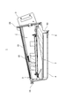
- FIG. 1 is a perspective view showing a crime prevention light (lighting fixture) according to an embodiment of the present invention.
- FIG. 2 is a perspective view showing the crime prevention light from behind.
- FIG. 3 is a view showing a crime prevention light, wherein (A) is a plan view, (B) is a side view, (C) is a bottom view, (D) is a front view, and (E) is a rear view.
- FIG. 4 is a cross-sectional view taken along line AA of FIG.
- FIG. 5 is a cross-sectional view taken along the line BB in FIG.
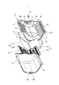
- FIG. 6 is an exploded perspective view of the crime prevention light with the light source section disassembled.
- FIG. 1 is a perspective view showing a crime prevention light (lighting fixture) according to an embodiment of the present invention.
- FIG. 2 is a perspective view showing the crime prevention light from behind.
- FIG. 3 is a view showing a crime prevention light, wherein (A) is a plan view, (
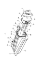
- FIG. 7 is an exploded perspective view of the crime prevention light in which the power supply unit is disassembled.
- FIG. 8 is a view showing the instrument body, (A) is a plan view, (B) is a side view, (C) is a bottom view, (D) is a front view, and (E) is a rear view.
- FIG. 9 is a perspective view showing a light source unit.
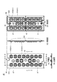
- FIG. 10 is an exploded perspective view showing the LED module.
- FIG. 11 is a view showing the lens cover together with the LED, (A) is a plan view, (B) is a front view, (C) is a side view, and (D) is a bottom view.
- FIG. 12 is a cross-sectional view showing the lens cover of FIG.
- FIG. 11 is a CC cross-sectional view
- (B) is a DD cross-sectional view
- (C) is an EE cross-sectional view.
- FIG. 13 is a cross-sectional view taken along the line FF of FIG.
- FIG. 14 is an explanatory view of light distribution of the crime prevention light.
- FIG. 15 is a perspective view showing a crime prevention light provided with a glove according to a modification of the present invention.
- FIG. 16 is a cross-sectional view taken along the line FF of FIG.
- FIG. 17 is an exploded perspective view showing a crime prevention light provided with a device body according to a modification of the present invention.
- FIG. 18 is a view showing FIG. 17 from the front lower side.
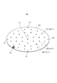
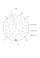
- FIG. 19 is a perspective view showing the LED substrate of the present invention.
- FIG. 20 is a plan view of FIG.
- FIG. 1 is a perspective view showing a crime prevention light 1 according to the present embodiment
- FIG. 2 is a perspective view showing the crime prevention light 1 from the rear
- FIG. 3 is a view showing the crime prevention light 1.
- FIG. 3 (A) is a plan view
- FIG. 3 (B) is a side view
- FIG. 3 (C) is a bottom view
- FIG. 3 (D) is a front view
- 3 (E) is a rear view.
- 4 is a cross-sectional view taken along the line AA of FIG. 3
- FIG. 5 is a cross-sectional view taken along the line BB of FIG.
- FIG. 6 is an exploded perspective view of the crime prevention light 1 in which the light source unit 6 is disassembled.
- the glare zone ⁇ in which a person feels glare is arctan (L / (T-1. 5)) It was found that it was 60 to 80 °.
- (T-1.5) corresponds to the height of the lamp viewed from the height (about 1.5 m) of the pedestrian's eyes.
- this glare zone ⁇ it has been found that glare can be reduced by setting the illuminance in front of the eye to 8 lx or less and the equivalent screen brightness to 0.2 cd / m 2 or less.
- glare can be reduced by setting the maximum luminance of the lamp to 170,000 cd / m 2 or less and the average luminance of the lamp to 53,000 cd / m 2 or less.
- the applicant has a lower light emitting surface luminance as the area of the light emitting portion (hereinafter referred to as an area above the light source) recognized by a person is larger in the comparison between the instruments which can obtain the same luminous flux with the same instrument. And we found that we could reduce glare. Furthermore, the applicant has found that, by making the central part of the light emitting part darker than the edge of the light emitting part, the area where the luminance distribution on the light emitting part can be felt uniform is increased and the glare can be felt low. I got The crime prevention light 1 is configured to reduce glare on the basis of such knowledge.
- the crime prevention light 1 illuminates a street with a predetermined brightness for the purpose of crime prevention, and as shown in FIG. 1 to FIG.
- the instrument main body 2 of the present embodiment is formed in a thin plate having a substantially rectangular shape in a bottom view extending from the front end 2A on the road surface side to the rear end 2B.
- the rear end 2B is provided with a fixing fitting 3 for fixing the instrument body 2 to a fastener Q fixed to, for example, a power pole P or the like.
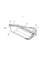
- the instrument body 2 is provided with a resin glove 4 covering the irradiation opening 8 on the bottom surface of the instrument body 2 with the entire bottom surface opened as the irradiation opening 8.
- the mounting surface 5 is integrally formed in the irradiation opening 8, and the LED module (light emitting element module) 10 is assembled
- the light source unit 6 is configured to have a light distribution that illuminates a wide area extending in the traffic direction of the street corresponding to both sides of the instrument body 2 as well as directly under the instrument body 2 (including the front side) in the street There is.
- the light source unit 6 includes the LED module 10 that illuminates each of two directions of the traffic direction.
- the LED module 10 includes a plurality of (22 in the illustrated example) LEDs (light emitting elements) 11.
- the fixture body 2 also includes a power supply housing 20 for storing a power supply (power supply) 7 for lighting the LED module 10, and the power storage 20 and the mounting surface 5 are integrally formed.
- the instrument body 2 is formed using a material (for example, aluminum or an aluminum alloy) which is corrosion resistant enough to withstand outdoor use and which has high thermal conductivity. By using a high thermal conductivity material, the heat generated by the LED module 10 is dissipated from the fixture body 2 and the light source temperature of the LED module 10 is maintained at a temperature suitable for light emission operation.
- the instrument body 2 is provided with a surrounding wall 31 having a rectangular frame shape in a plan view and surrounding the mounting surface 5, and the inside of the light source chamber 32 inside the surrounding wall 31 is made watertight.
- the light source chamber 32 is to be waterproofed. That is, the tip 31A is in close contact with the packing 9 of the glove 4 over the entire circumference of the surrounding wall 31, whereby the inside of the surrounding wall 31 is sealed in a watertight manner.
- the globe 4 is formed of a light transmissive and diffusive material (for example, resin), and the light of the LED 11 is diffused by the globe 4 to reduce glare.
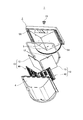
- the globe 4 is formed by bulging in the downward direction so as to cover the mounting surface 5 from the lower side, and the lower portion of the globe 4 is a flat portion 4A formed flat.
- the glove 4 is formed with a through hole 4B penetrating the glove 4 in the vertical direction, and a filter 36 (FIG. 17) is provided in the through hole 4B.
- the filter 36 is configured to include, in addition to dust, a water / vapor impermeable filter that does not transmit water and water vapor.
- the filter 36 removes dust and water vapor of air passing through the through holes 4B.
- the air in the light source chamber 32 is heated and expanded by the heat generation of the LED module 10, so the air in the light source chamber 32 is discharged to the outside from the through hole 4B.
- the LED module 10 is turned off, the air heated and expanded by the heat generation of the LED module 10 is cooled by the outside air temperature etc. and contracted, so the outside air enters the light source chamber 32 from the through hole 4B. It becomes.
- FIG. 7 is an exploded perspective view of the crime prevention light 1 in which the power supply unit 7 is disassembled.
- the power supply housing 20 extends from the front end 2A to the rear end 2B of the instrument body 2 and opens in the rear end 2B as a housing opening 21 (in the present embodiment, a corner It is formed in a tubular shape.
- the upper surface 20A of the power supply housing 20 is provided to be inclined so that the height is reduced from the rear end 2B to the front end 2A.
- the tool body 2 is molded by casting (more specifically, aluminum die casting), and when the tool body 2 is molded by inclining the upper surface 20A of the power supply housing portion 20, The tool body 2 can be easily formed.
- the power supply unit 7 is configured by attaching a power supply substrate 7B on which the electronic member 7A is mounted to a power supply mounting plate 7C. Further, an illuminance sensor 7D is attached to the power supply mounting plate 7C.
- the electrical components such as the electronic member 7A and the illuminance sensor 7D are provided with insulating sheets such as a power supply insulating sheet 7E and a sensor insulating sheet 7F.
- the power supply unit 7 is accommodated in the power supply accommodation unit 20 from the accommodation unit opening 21.
- a sensor exposure hole 22 for exposing the illuminance sensor 7D is formed on the top surface 20A of the power supply housing 20 at a position corresponding to the illuminance sensor 7D.
- a sensor cover 23 is attached to the sensor exposure hole 22.
- the illuminance sensor 7D is provided on the upper surface 70A of the power supply housing 20 so that the light from the light source unit 6 does not affect the detection of the illuminance sensor 7D.
- the position is not limited to this.
- the illuminance sensor 7D may be provided, for example, on the side surface of the instrument main body 2 as long as the light from the light source unit 6 does not affect the detection of the illuminance sensor 7D.
- the main body lid 25 is fixed to the housing opening 21 via the packing 24, and the fixing metal fitting 3 described above is fixed to the main body lid 25.
- a wire lead-in hole 26 is opened in the main body lid 25, and an electrical wire (not shown) on the primary side is drawn into the power supply housing 20 from the outside through the wire lead-in hole 26.
- the bushing 27 is fitted to the wiring lead-in hole 26, and wiring is made to the bushing 27 through the electrical wiring on the primary side.
- the power supply housing 20 is configured to be waterproof by the sensor cover 23, the packing 24, and the bushing 27.
- FIG. 8 is a view showing the instrument main body 2 from which the globe 4 and the LED module 10 are removed
- FIG. 8 (A) is a plan view
- FIG. 8 (B) is a side view
- FIG. 8 (C) is a bottom view
- 8 (D) is a front view
- FIG. 8 (E) is a rear view.
- the mounting surface 5 is integrally formed with the power supply accommodating portion 20 so as to surround the outer periphery of the power supply accommodating portion 20, more specifically, the bottom surface 20B and both side surfaces 20C and 20D, as shown in FIG.
- the power supply housing portion 20 and the mounting surface 5 are integrally formed of a heat conductive material to constitute the tool main body 2, the heat of the LED module 10 is dissipated from the entire tool main body 2 including the power supply housing portion 20. Since it can do, the heat dissipation of the crime prevention light 1 can be improved. Further, since the power supply housing 20 and the mounting surface 5 are integrally formed and the power supply housing 20 is used as a housing, no mounting bracket for mounting the LED module 10 is required, so the crime prevention light 1 can be miniaturized. . Moreover, since the crime prevention light 1 has a configuration in which the attachment surface 5 integrally formed in the power supply housing portion 20 is covered with the glove 4, the structure can be simplified.
- the mounting surface 5 is disposed obliquely with respect to the horizontal plane H. As a result, compared to the case where the mounting surface 5 is arranged horizontally, the visible area of the LED module 10 in the glare zone ⁇ becomes wider, and as described above, glare can be reduced.
- the mounting angle ⁇ of the mounting surface 5 from the horizontal surface H is set to 20 ° or more and 40 ° or less. By setting the mounting angle ⁇ to 20 ° or more, the LED module 10 can be disposed facing away, so that it can be illuminated far away. Further, by setting the attachment angle ⁇ to 40 ° or less, it is possible to suppress the upward upward luminous flux which is unnecessary for the crime prevention light 1.
- two mounting surfaces 5 are disposed back to back so that irradiation can be performed far in both directions in the traffic direction of the road surface, so that irradiation can be performed relatively widely.
- the two mounting surfaces are provided obliquely with respect to the horizontal surface H and disposed in a valley shape, and in the present embodiment, the two mounting surfaces 5 are connected at the lower end 5B and disposed in a substantially V shape in front view There is.
- the power supply accommodation portion 20 is disposed in the valley portion 33 between the two attachment surfaces 5 such that the bottom surface 20B of the power supply accommodation portion 20 is lower than the upper end 5A of the attachment surface 5.
- the tool main body is compared with the case where the power supply accommodating portion 20 is arranged above the mounting surface 5
- the height of 2 can be reduced.
- the length of the front-back direction of the instrument main body 2 can be restrained.
- a wire lead-out hole 28 for drawing out the electric wire is formed at the tip 20E of the power supply accommodating portion 20, and a secondary side electric wire (not shown) extending from the power source 7 through the wire lead-out hole 28. ) Is drawn out to the light source chamber 32 outside the power supply housing 20.
- the LED module 10 is arranged such that the connector 12 for connecting the electrical wiring on the secondary side is located on the tip 20 E side of the power supply housing 20, and the electrical wiring passed through the wiring extraction hole 28 is It is connected to the connector 12.
- the wiring extraction hole 28 is formed at the tip 20E of the power supply housing 20 and the electrical wiring on the secondary side is connected at the tip 20E, the electrical wiring on the secondary side can be wired with the minimum necessary length.
- the front end 20E of the power supply housing 20 is on the same plane as the front end 5C of the mounting surface 5, but the front end 20E of the power supply housing 20 coincides with the front end 5C of the mounting surface 5 in the front-rear direction You do not have to.
- the upper end 5A of the mounting surface 5 and the power supply accommodating portion 20 are connected such that the upper surface 2C of the tool body 2 located above the mounting surface 5 is flat. .
- the crime prevention light 1 is attached with the tip 2A facing upward so that the upper surface 2C is inclined rearward and downward. As a result, rainwater or snow falling on the upper surface 2C is moved backward and dropped smoothly.
- the upper surface 2C is formed in a planar shape, it is possible to prevent dust such as fallen leaves from collecting on the upper surface 2C.
- the thickness of the outer edge portion 34 surrounded by the upper end 5A portion of the mounting surface 5 and the upper surface 2C is increased as shown in FIG.
- a defect in which the surface of the thick portion of the molded product can be dented may occur. Therefore, in the present embodiment, a plurality of grooves 35 are formed in the outer edge portion 34 of the mounting surface 5.
- the grooves 35 are provided from the upper end 5 A of the mounting surface 5 to a predetermined width, and are disposed between the plurality of LEDs 11.
- the thickness of the outer edge portion 34 can be reduced by the groove 35, it is possible to prevent the sink from occurring in the device body 2. Moreover, since the area which contacts the air of the instrument main body 2 becomes large by forming the groove
- the rear end 5D of the mounting surface 5 protrudes below the lower end 5B of the mounting surface 5, but is not limited thereto.
- the lower portion of the rear end 5D is made to coincide with the lower end 5B. May be
- the rear part of the glove 4 is supported at the lower part of the rear end 5D.
- the rear end 5D is located on the front end side of the rear end 2B of the power supply housing 20, it may be coincident with the rear end 2B.
- the LED module 10 is disposed on each of the two mounting surfaces 5 configured as described above.
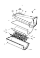
- FIG. 9 is a perspective view showing the light source unit 6, and FIG. 10 is an exploded perspective view showing the LED module 10.
- FIG. 11 shows the lens cover 40 together with the LED 11.
- FIG. 11 (A) is a plan view
- FIG. 11 (B) is a front view
- FIG. 11 (C) is a side view
- FIG. 12 is a cross-sectional view showing the lens cover 40 of FIG. 11,
- FIG. 12 (A) is a CC cross-sectional view,
- FIG. 12 (B) is a DD cross-sectional view, and
- FIG. 12 (C) is an EE cross section.
- FIG. FIG. 13 is a cross-sectional view taken along the line FF of FIG.
- two LED modules 10 are arrange
- the LED module 10 arranges a plurality of LEDs 11 on a rectangular plate-like LED substrate (substrate) 13 and covers the LED substrate 13 with a lens cover 40 having a lens 41 for each LED 11. It is provided in a bar shape.
- the LED module 10 is configured such that the same amount of current flows through the plurality of LEDs 11, and one end of the LED substrate 13 in the longitudinal direction is provided with a connector 12 for connecting electrical wiring from the power supply unit 7.
- a screw hole 14 is formed substantially at the center of the LED substrate 13, and the LED module 10 is assembled by screwing the mounting surface 5 at substantially the center of the LED substrate 13. As shown in FIG. 5, the screw 15 at the time of screwing penetrates the LED substrate 13 and the lens cover 40, and these are fastened and fixed to the mounting surface 5.
- the LED 11 emits white light, and as shown in FIG. 10, the LED 11 is mounted with the optical axis K directed substantially perpendicularly to the substrate surface of the LED substrate 13.
- the LED 11 can be regarded as a substantially point light source that emits light from the light emitting portion including the light emitting point G (a point of maximum luminance) (FIG. 13), and the plurality of LEDs 11 allow the light emitting point G to be viewed independently. , Are spaced apart. This interval is set according to the light output of the LED 11.
- that the light emitting points G are viewed independently does not mean that the light emitting points G of the adjacent LEDs 11 are not completely dark, but may have a certain degree of brightness.
- the evaluation of whether the light emitting point G can be seen independently is the height of the line of sight of the pedestrian (approximately 1.5 m), and the effective visual field when facing the walking direction (upper and lower 20 °, left and right 30 °) It is evaluated by. As described above, as described above, glare can be reduced by arranging the LEDs 11 so that the light of the plurality of LEDs 11 can be viewed independently.
- the LED 11 is configured of a plurality of outer LEDs (outer light emitting elements) 11A disposed along the edge 13A of the LED substrate 13 and an inner LED (inner light emitting element) 11B disposed inside the outer LEDs 11A.
- the LEDs 11 are arranged in multiple rows (three rows in the illustrated example) in the left-right direction, and are arranged in a staggered manner by shifting the positions in the arrangement direction. More specifically, the outer LEDs 11A in both outer rows are disposed at the same front and back position, and the inner LEDs 11B in the inner row are disposed so as not to overlap with the outer LEDs 11A in both outer rows in the left-right direction There is.
- the LEDs 11 are arranged in multiple rows in a staggered manner, interference of light between the LEDs 11 can be prevented, and uneven illumination can be prevented. Furthermore, when the lens cover 40 is injection molded using a material such as resin, the material is easily made to flow to the portion of the lens 41 by arranging the lenses 41 in a zigzag shape, and the lens cover 40 can be easily formed.
- the light output of the plurality of inner LEDs 11B is smaller than the light output of the plurality of outer LEDs 11A. More specifically, the number (6) of the inner LEDs 11B in the inner row is smaller than the number (8) of the outer LEDs 11A in both outer rows. As a result, the substantially central portion of the LED module 10 becomes darker than the edge, so that the brightness distribution on the LED module 10 becomes uniform, and glare can be reduced. In addition, since the substantially central portion of the LED module 10 becomes darker than the edge portion, the area in which the brightness distribution on the visible side of the LED module 10 in the glare zone ⁇ is felt to be uniform is increased, and the glare is felt low. Furthermore, by reducing the number of the inner LEDs 11B, it becomes easy to arrange the LEDs 11 in a staggered manner.
- a high efficiency LED (high efficiency light emitting element) 11C having a light emission efficiency higher than that of the outside LED 11A is used for at least one of the inside LEDs 11B.
- the high efficiency LED 11C the number of the inner LEDs 11B can be reduced while maintaining a sufficient light output.
- LED which is not high efficiency is low efficiency LED11D.
- the low efficiency LED (low efficiency light emitting element) 11D is disposed between the high efficiency LEDs 11C in the inner row.
- the lens cover 40 has a flat plate portion 42 made of transparent resin, and the lens 41 is integrally resin-molded on the surface 42A of the flat plate portion 42.
- the flat plate portion 42 has a substantially rectangular shape, and a screw hole 43 is formed substantially at the center thereof, and the lens cover 40 is fixed to the mounting surface 5 through the screw 15 (FIG. 5).
- the LED substrate 13 and the lens cover 40 are tightened together with a screw to prevent positional deviation between the lenses 41 and the LEDs 11 of the LED substrate 13.
- a positioning boss 44 is provided upright in that surface, and in the surface of the LED substrate 13 As shown at 10, a positioning hole 16 is formed to receive the positioning boss 44.
- the LED substrate 13 and the lens cover 40 are positioned at more accurate positions.
- the lens cover 40 includes the lens 41 for each LED 11, accurate positioning of these lenses 41 is performed at one time.
- one of the substantially central portions of the positioning holes 16 of the LED substrate is of the same size as the screw holes 14 of the LED substrate 13 and disposed at symmetrical positions.
- Each of the lenses 41 is disposed at a position overlapping the corresponding LED 11 as shown in FIG.
- the lens 41A corresponding to the high efficiency LED 11C has the same shape, and controls the emitted light of the high efficiency LED 11C with the same light distribution characteristic.
- the lens 41B corresponding to the low efficiency LED 11D has the same shape, and controls the emission light of the low efficiency LED 11D with the same light distribution characteristic. Specifically, as shown in FIG.
- the lens 41 has an incident surface 45 curved in a convex shape (that is, a concave shape in a bottom view) on the inner surface of the lens, and a convex shape on the lens outer surface with respect to the incident surface 45
- the light emitting surface 46 of the A concave portion is formed on the back surface of the lens 41 by the incident surface 45, and the LED 11 enters the concave portion.
- the LED 11 radiates light to substantially the entire periphery radially around the optical axis K, and the lens 41 distributes the emitted light in one direction (lateral direction in this embodiment) (one-sided light distribution) It is configured. Specifically, the LED 11 is disposed close to one side in the left-right direction with respect to the emission surface 46 formed in a substantially hemispherical shape, and the lens 41 emits light directed to the other far side in the left-right direction. As described above, since the lens 41 is configured to distribute the light of the LED 11 to a distant place, the lens 41 can be irradiated to a distant place in the traffic direction of the road surface, so that it can be irradiated relatively widely.
- the lens 41B corresponding to the low efficiency LED 11D is configured to emit light farther than the lens 41A corresponding to the high efficiency LED 11C.
- the lens cover 40 is provided with an exposure opening 47 for exposing a part of the plurality of inner LEDs 11B.
- the exposure opening 47 is disposed closer to the edge 13 A of the LED substrate 13. As a result, the outside of the LED module 10 becomes bright, so that the luminance distribution on the LED module 10 becomes even, and glare can be reduced.
- the lens cover 40 is injection-molded using a material such as resin, the material can easily flow to the portion of the lens 41 by providing the exposure opening 47 on the side close to the edge 13A of the LED substrate 13. Can be easily formed.
- the high efficiency LED 11C is used for the inner LED 11B near the edge 13A of the LED substrate 13, and the exposure opening 47 is provided at the position of the high efficiency inner LED 11B.
- the LED module 10 is configured to be rotationally symmetrical.
- the lens cover 40 is configured to be rotationally symmetrical with respect to the LED substrate 13.
- the lens cover 40 has a connector groove 48 which avoids the connector 12 of the LED substrate 13, but has two connector grooves 48 for the connector 12.
- the LED substrate 13 has two holes at the center, one of which functions as a screw hole 14 corresponding to the screw hole 43 of the lens cover 40 and the other for positioning corresponding to the positioning boss 44 of the lens cover 40 It functions as the hole 16. Since the LED module 10 is configured to be rotationally symmetrical as described above, the LED module 10 can be made common to the two mounting surfaces 5, so that the kind of parts can be reduced and the manufacturing process can be simplified.
- the LED module 10 by arranging the LED module 10 to one side light distribution and arranging the LED module 10 on the two mounting surfaces 5 provided back to back, it is possible to irradiate each far in both directions of the traffic direction of the road surface. It can be irradiated relatively widely.
- the light of the low efficiency LED 11D mainly disposed at the edge 13A of the LED substrate 13 is irradiated to the distant area through the lens 41A.
- the light of the high efficiency LED 11 ⁇ / b> C, which is disposed inside and corresponds to the exposure opening 47 is irradiated via the exposure opening 47 to an area near immediately below.
- the light of the high efficiency LED 11C, which is disposed inside and corresponds to the lens 41B is irradiated through the lens 41B between the distant area and the area immediately below.
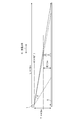
- FIG. 14 is an explanatory view of light distribution of the crime prevention light 1.
- the crime prevention light 1 configured as described above reduces the glare, and the crime prevention light recommendation standard "class B" (non-profit incorporated corporation Japan crime prevention equipment association technical standard SES E1901-3), the installation interval of the crime prevention light 1 is 38 m Can be achieved by That is, as shown in FIG. 14, the crime prevention light 1 is disposed at a height T of 4.5 meters from the road surface R of a 5 meter wide street, and the traffic of the road surface R from directly below with one LED module 10 It is possible to irradiate the area of the whole road surface extending 19 m ahead along one direction of the direction S.
- class B non-profit incorporated corporation Japan crime prevention equipment association technical standard SES E1901-3
- the crime prevention light 1 has an illuminance in front of the eye of 8 lx or less, an equivalent luminous screen brightness of 0.2 cd / m 2 or less, a maximum brightness of the lamp of 170,000 cd / m 2 or less, and an average brightness of the lamp of 53, As it becomes less than 000 cd / m 2 , glare can be reduced as described above.
- the plurality of LEDs 11 are disposed along the edge 13A of the LED substrate 13, and the LEDs 11 are disposed inside the plurality of LEDs 11.
- the light output of the outer LED 11 disposed along the edge 13A of the LED substrate 13 is smaller than the light output.
- the substantially central portion of the LED module 10 becomes darker than the edge, so that the luminance distribution on the LED module 10 becomes uniform, and glare can be reduced.
- the substantially central portion of the LED module 10 becomes darker than the edge portion, the area in which the brightness distribution on the visible side of the LED module 10 in the glare zone ⁇ is felt to be uniform is increased, and the glare is felt low.
- the lens cover 40 is provided which has the lens 41 for each LED 11 and covers the LED substrate 13, and the exposure opening 47 for exposing the inner LED 11 is formed in the lens cover 40.
- the exposure opening 47 is formed on the side closer to the edge 13A of the LED substrate 13, the outside of the LED module 10 is brightened, so the luminance distribution on the LED module 10 can be improved. It becomes uniform and can reduce glare.
- the lens cover 40 is injection molded using a material such as resin, the exposed opening 47 is provided on the side close to the edge 13A of the LED substrate 13 so that the material can easily flow to the lens 41. Can be easily formed.
- the inner LED 11 is configured to be a light emitting element having a light emission efficiency higher than that of the outer LED 11. With this configuration, the number of inner LEDs 11 can be reduced while maintaining a sufficient light output.
- the LEDs 11 are arranged in a plurality of rows in a zigzag, interference of light between the LEDs 11 can be prevented, and uneven illuminance can be prevented. Moreover, it becomes easy to arrange
- the above-mentioned embodiment is one mode of the present invention, and it is needless to say that it can be suitably changed in the range which does not deviate from the meaning of the present invention.
- the glove 4 whole was formed with the material which has diffusivity, it is not limited to this.
- the globe 4 generates a relatively large amount of upper luminous flux at the edge 4C (FIG. 6) close to the LED 11 due to diffusion. Therefore, for example, as in the glove 104 shown in FIGS. 15 and 16, the diffusivity of the upper light beam diffusion portion (portion) 104C that causes light flux to be relatively higher above the horizontal by diffusion is made lower than that of the other portions. It is also good.
- the upper luminous flux diffusing portion 104C is a portion up to the edge 104D located above the lens 41 closest to the globe 104, but if it is above the glare zone ⁇ , the upper luminous flux diffusing portion 104C
- the scope is not limited to this.
- the upper end 5A of the mounting surface 5 and the power supply accommodating portion 20 are connected in a planar manner, and a plurality of grooves 35 are formed in the outer edge portion 34 of the mounting surface 5 which is thick.
- the upper end 5A of the mounting surface 5 and the power supply accommodating portion 20 may be connected to the upper surface 2C of the device main body 2 so as to have a recess 202D.
- the groove 35 formed in the mounting surface 5 can be omitted.
- LED11 was arrange
- positioning of LED11 is not limited to this.
- the LEDs 11 may be arranged in a circle on the LED substrate 313.
- the plurality of LEDs 11 are disposed along the edge 13 A of the LED substrate 113 and the LEDs 11 are disposed inside the plurality of LEDs 11, and the light output of the inner LED 11 is along the edge 13 A of the LED substrate 13 It is configured to be smaller than the light output of the outside LED 11 disposed.
- high efficiency LED11C with high luminous efficiency is provided inside.
- the LEDs 11 are arranged in multiple rows (three rows in the illustrated example) in the radial direction, and the positions are shifted in the circumferential direction which is the arrangement direction.
- the crime prevention light 1 is illustrated as a lighting fixture concerning the present invention, of course, the present invention is applicable to various lighting fixtures used outdoors or indoors.
Landscapes
- Engineering & Computer Science (AREA)
- General Engineering & Computer Science (AREA)
- Non-Portable Lighting Devices Or Systems Thereof (AREA)
- Arrangement Of Elements, Cooling, Sealing, Or The Like Of Lighting Devices (AREA)
- Fastening Of Light Sources Or Lamp Holders (AREA)
Priority Applications (1)
| Application Number | Priority Date | Filing Date | Title |
|---|---|---|---|
| AU2014367903A AU2014367903B2 (en) | 2013-12-18 | 2014-12-10 | Light-emitting element module and illumination device |
Applications Claiming Priority (2)
| Application Number | Priority Date | Filing Date | Title |
|---|---|---|---|
| JP2013-261805 | 2013-12-18 | ||
| JP2013261805A JP5776757B2 (ja) | 2013-12-18 | 2013-12-18 | 発光素子モジュール及び照明器具 |
Publications (1)
| Publication Number | Publication Date |
|---|---|
| WO2015093359A1 true WO2015093359A1 (ja) | 2015-06-25 |
Family
ID=53402708
Family Applications (1)
| Application Number | Title | Priority Date | Filing Date |
|---|---|---|---|
| PCT/JP2014/082629 Ceased WO2015093359A1 (ja) | 2013-12-18 | 2014-12-10 | 発光素子モジュール及び照明器具 |
Country Status (3)
| Country | Link |
|---|---|
| JP (1) | JP5776757B2 (enExample) |
| AU (1) | AU2014367903B2 (enExample) |
| WO (1) | WO2015093359A1 (enExample) |
Citations (6)
| Publication number | Priority date | Publication date | Assignee | Title |
|---|---|---|---|---|
| JP2010049865A (ja) * | 2008-08-20 | 2010-03-04 | Sharp Corp | 照明機器 |
| WO2011036953A1 (ja) * | 2009-09-28 | 2011-03-31 | シャープ株式会社 | 照明装置、表示装置、及びテレビ受信装置 |
| WO2011070872A1 (ja) * | 2009-12-08 | 2011-06-16 | シャープ株式会社 | 照明装置、表示装置、及びテレビ受信装置 |
| JP2011204397A (ja) * | 2010-03-24 | 2011-10-13 | Sony Corp | 照明装置 |
| JP2012513087A (ja) * | 2008-12-18 | 2012-06-07 | アン,ヘンス | Led街灯 |
| JP5554432B1 (ja) * | 2013-03-11 | 2014-07-23 | 株式会社東芝 | 照明装置 |
-
2013
- 2013-12-18 JP JP2013261805A patent/JP5776757B2/ja not_active Expired - Fee Related
-
2014
- 2014-12-10 AU AU2014367903A patent/AU2014367903B2/en not_active Ceased
- 2014-12-10 WO PCT/JP2014/082629 patent/WO2015093359A1/ja not_active Ceased
Patent Citations (6)
| Publication number | Priority date | Publication date | Assignee | Title |
|---|---|---|---|---|
| JP2010049865A (ja) * | 2008-08-20 | 2010-03-04 | Sharp Corp | 照明機器 |
| JP2012513087A (ja) * | 2008-12-18 | 2012-06-07 | アン,ヘンス | Led街灯 |
| WO2011036953A1 (ja) * | 2009-09-28 | 2011-03-31 | シャープ株式会社 | 照明装置、表示装置、及びテレビ受信装置 |
| WO2011070872A1 (ja) * | 2009-12-08 | 2011-06-16 | シャープ株式会社 | 照明装置、表示装置、及びテレビ受信装置 |
| JP2011204397A (ja) * | 2010-03-24 | 2011-10-13 | Sony Corp | 照明装置 |
| JP5554432B1 (ja) * | 2013-03-11 | 2014-07-23 | 株式会社東芝 | 照明装置 |
Also Published As
| Publication number | Publication date |
|---|---|
| AU2014367903A1 (en) | 2016-06-16 |
| JP5776757B2 (ja) | 2015-09-09 |
| AU2014367903B2 (en) | 2017-01-05 |
| JP2015118812A (ja) | 2015-06-25 |
Similar Documents
| Publication | Publication Date | Title |
|---|---|---|
| JP5630624B2 (ja) | 照明装置 | |
| JP5854117B2 (ja) | 照明器具 | |
| JP6111633B2 (ja) | 照明器具 | |
| JP6171298B2 (ja) | 照明器具 | |
| JP4882795B2 (ja) | 防犯灯 | |
| JP5772936B2 (ja) | 道路灯 | |
| JP5918835B2 (ja) | 照明装置 | |
| JP6024909B2 (ja) | ルーバ及びそれを用いた照明装置 | |
| JP6248988B2 (ja) | 発光素子モジュール及び照明器具 | |
| JP6186714B2 (ja) | 照明器具 | |
| JP2012216477A (ja) | 照明装置 | |
| JP5776757B2 (ja) | 発光素子モジュール及び照明器具 | |
| JP6795831B2 (ja) | 照明器具 | |
| JP2016024955A (ja) | 照明用レンズ、及び照明装置 | |
| JP2016024326A (ja) | 照明用レンズ、及び照明装置 | |
| JP5983258B2 (ja) | 光学素子、及び照明器具 | |
| AU2014367936B2 (en) | Illumination device | |
| WO2015093392A1 (ja) | 照明器具 | |
| JP2011018469A (ja) | 照明装置 | |
| JP5382075B2 (ja) | 防犯灯 | |
| JP6179050B2 (ja) | 照明装置 | |
| JP2012221598A (ja) | 照明装置 | |
| JP2017152413A (ja) | 照明装置 | |
| JP5655170B2 (ja) | 照明装置 | |
| JP2014049275A (ja) | 照明装置 |
Legal Events
| Date | Code | Title | Description |
|---|---|---|---|
| 121 | Ep: the epo has been informed by wipo that ep was designated in this application |
Ref document number: 14872857 Country of ref document: EP Kind code of ref document: A1 |
|
| ENP | Entry into the national phase |
Ref document number: 2014367903 Country of ref document: AU Date of ref document: 20141210 Kind code of ref document: A |
|
| NENP | Non-entry into the national phase |
Ref country code: DE |
|
| 122 | Ep: pct application non-entry in european phase |
Ref document number: 14872857 Country of ref document: EP Kind code of ref document: A1 |